Multi Tech Systems 92U13A16858 MTXDOT-NA1 User Manual tmp 0Btyto
Multi Tech Systems Inc MTXDOT-NA1 tmp 0Btyto
UserManual.wiki
>
Multi Tech Systems
>
92U13A16858 User Manual
>
user manual
Contents
1.
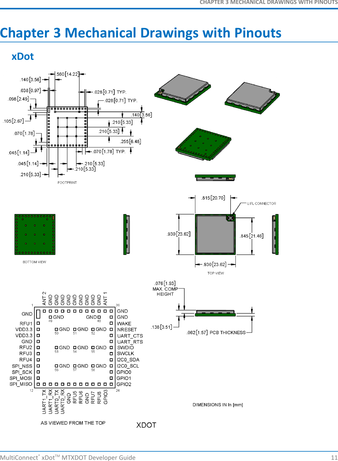
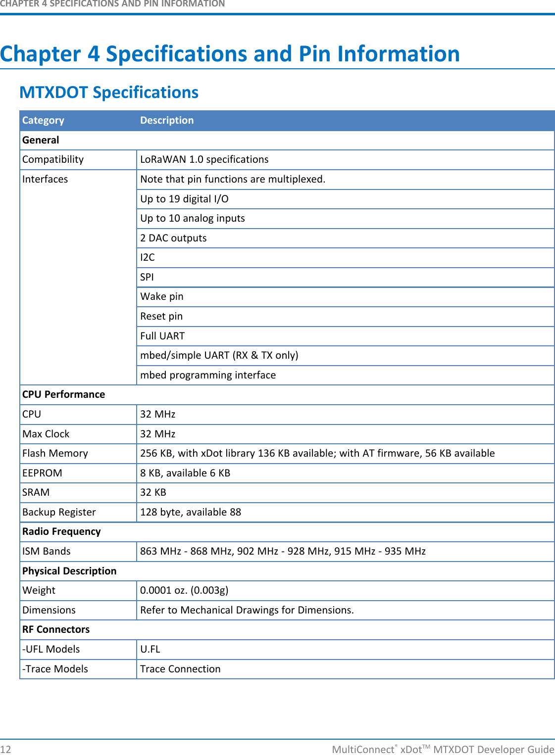
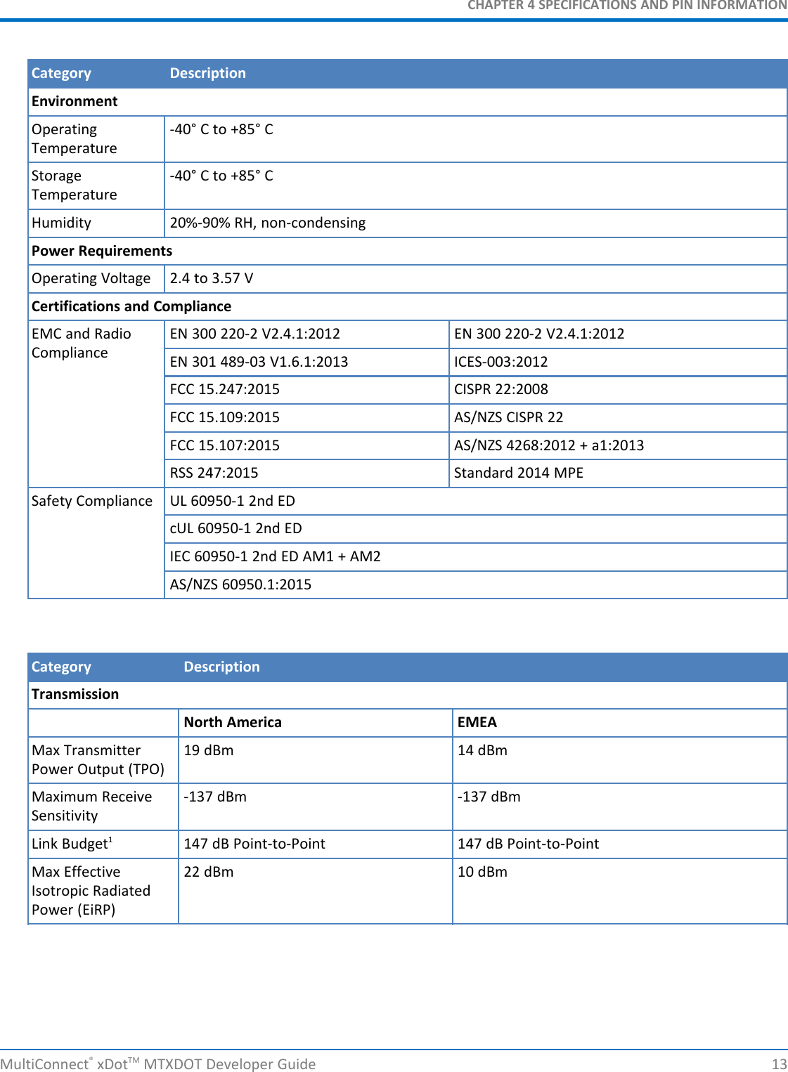
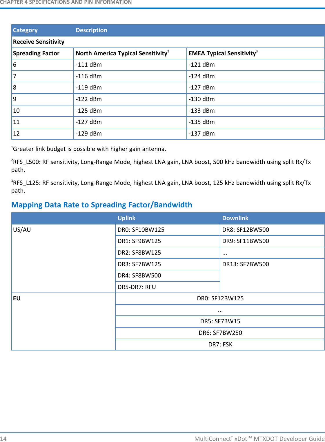
user manual
2.
MANUAL
3.
MANUAL ADDENDUM
4.
MANUAL PART 1
5.
MANUAL PART 2
6.
MANUAL PART 3
7.
MANUAL PART 4
user manual
Navigation menu
Upload a User Manual
Namespaces
Wiki Guide
HTML
PDF
Info
Views
User Manual
Discussion / Help
Navigation

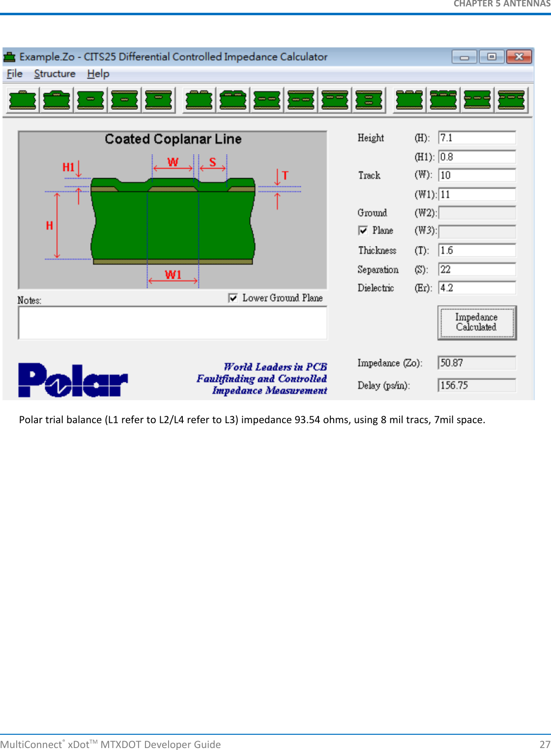
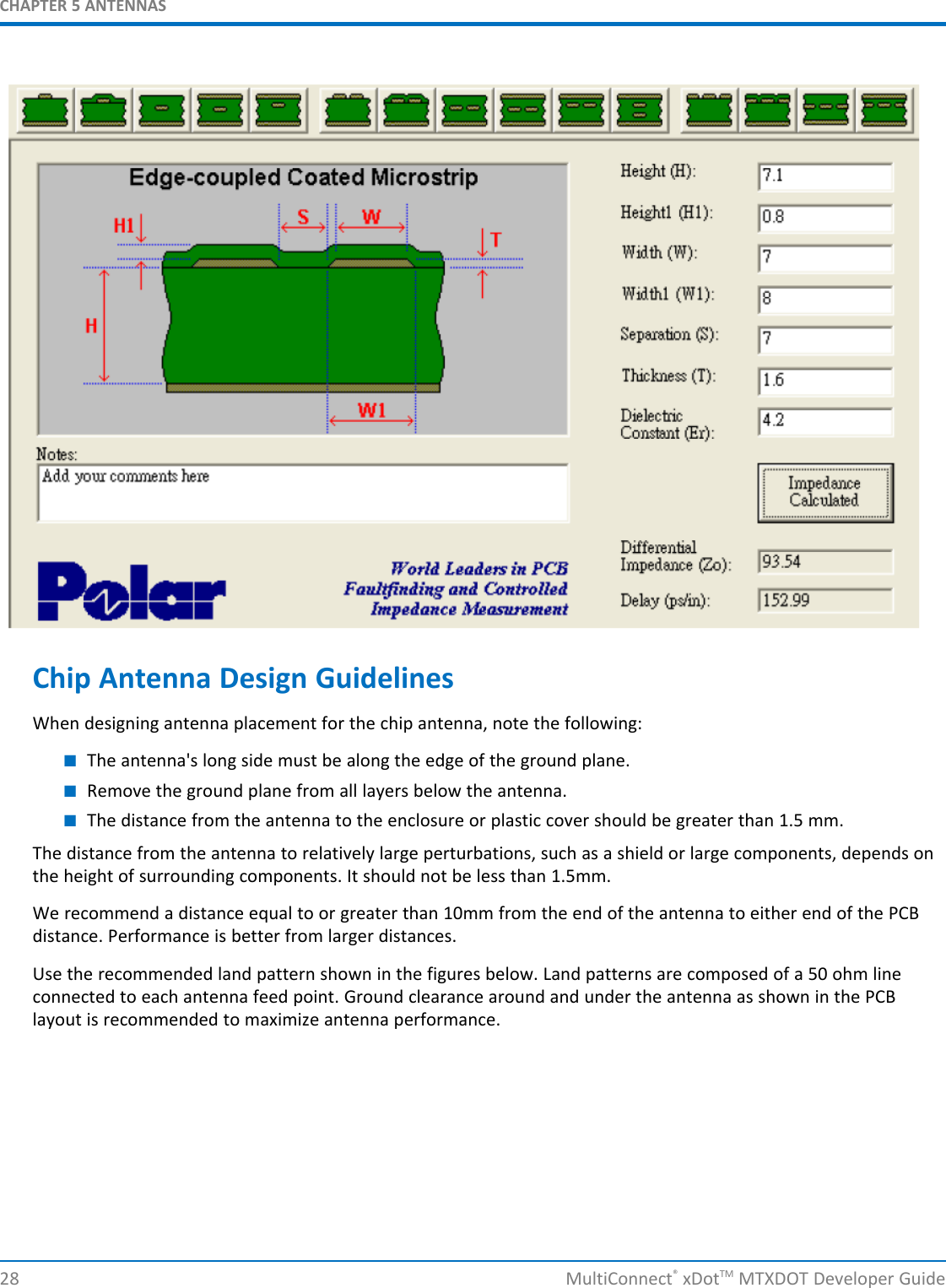
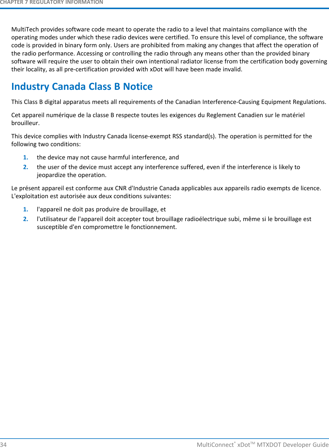
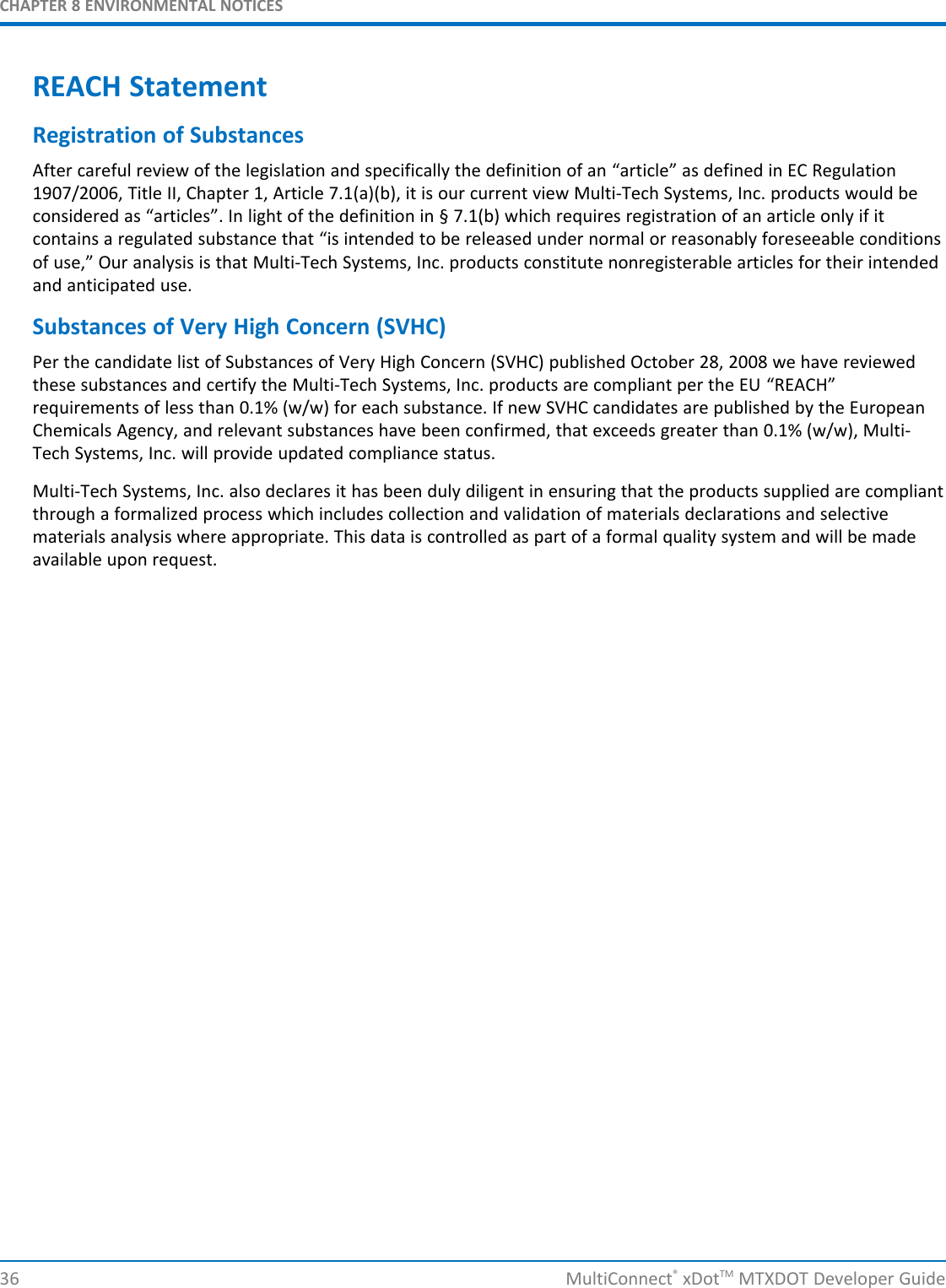
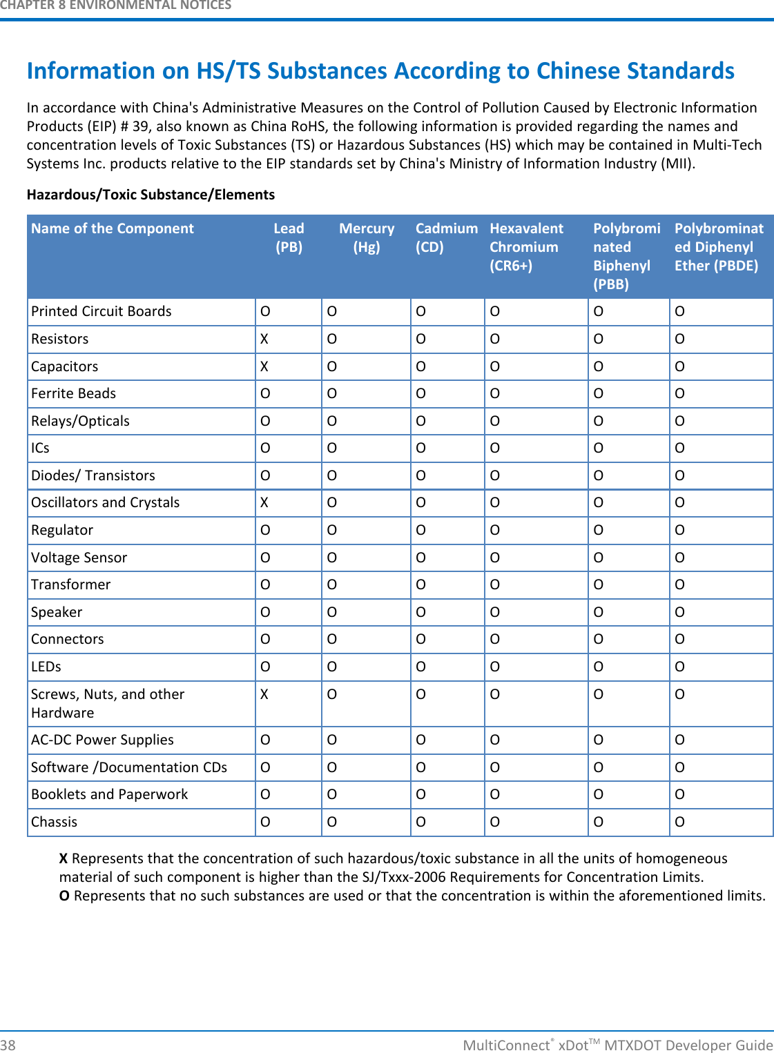
![CHAPTER 8 ENVIRONMENTAL NOTICESMultiConnect®xDotTM MTXDOT Developer Guide 37Restriction of the Use of Hazardous Substances (RoHS)Multi-Tech Systems, Inc.Certificate of Compliance2011/65/EUMulti-Tech Systems, Inc. confirms that its embedded products comply with the chemical concentration limitationsset forth in the directive 2011/65/EU of the European Parliament (Restriction of the use of certain HazardousSubstances in electrical and electronic equipment - RoHS).These MultiTech products do not contain the following banned chemicals1:■Lead, [Pb] < 1000 PPM■Mercury, [Hg] < 1000 PPM■Hexavalent Chromium, [Cr+6] < 1000 PPM■Cadmium, [Cd] < 100 PPM■Polybrominated Biphenyl, [PBB] < 1000 PPM■Polybrominated Diphenyl Ether, [PBDE] < 1000 PPMEnvironmental considerations:■Moisture Sensitivity Level (MSL) =1■Maximum Soldering temperature = 260C (in SMT reflow oven)1Lead usage in some components is exempted by the following RoHS annex, therefore higher lead concentrationwould be found in some modules (>1000 PPM);- Resistors containing lead in a glass or ceramic matrix compound.](https://usermanual.wiki/Multi-Tech-Systems/92U13A16858.user-manual/User-Guide-3192706-Page-37.png)