Multi Tech Systems 92U18H30862 MTCDTIP-LAT1-275x-915 User Manual MultiConnect ConduitTM Base Station IP67
Multi Tech Systems Inc MTCDTIP-LAT1-275x-915 MultiConnect ConduitTM Base Station IP67
UserManual.wiki
>
Multi Tech Systems
>
92U18H30862 User Manual
User Manual
Navigation menu
Upload a User Manual
Namespaces
Wiki Guide
HTML
PDF
Info
Views
User Manual
Discussion / Help
Navigation
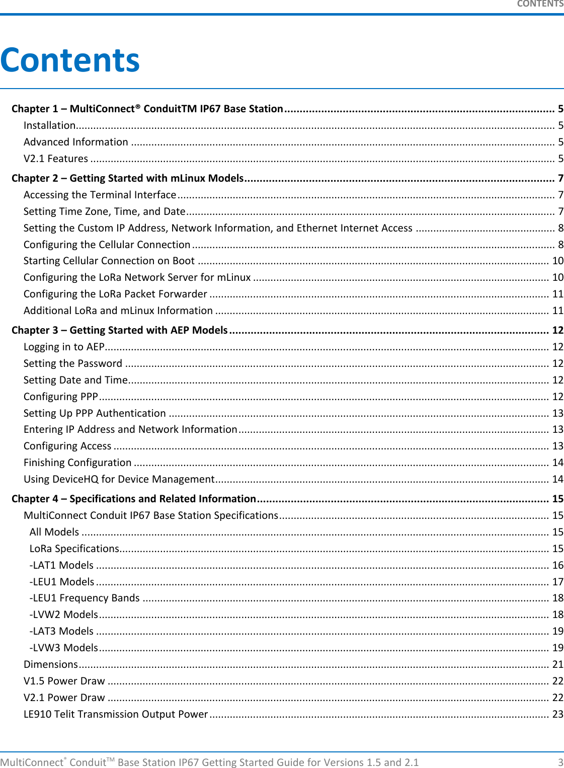
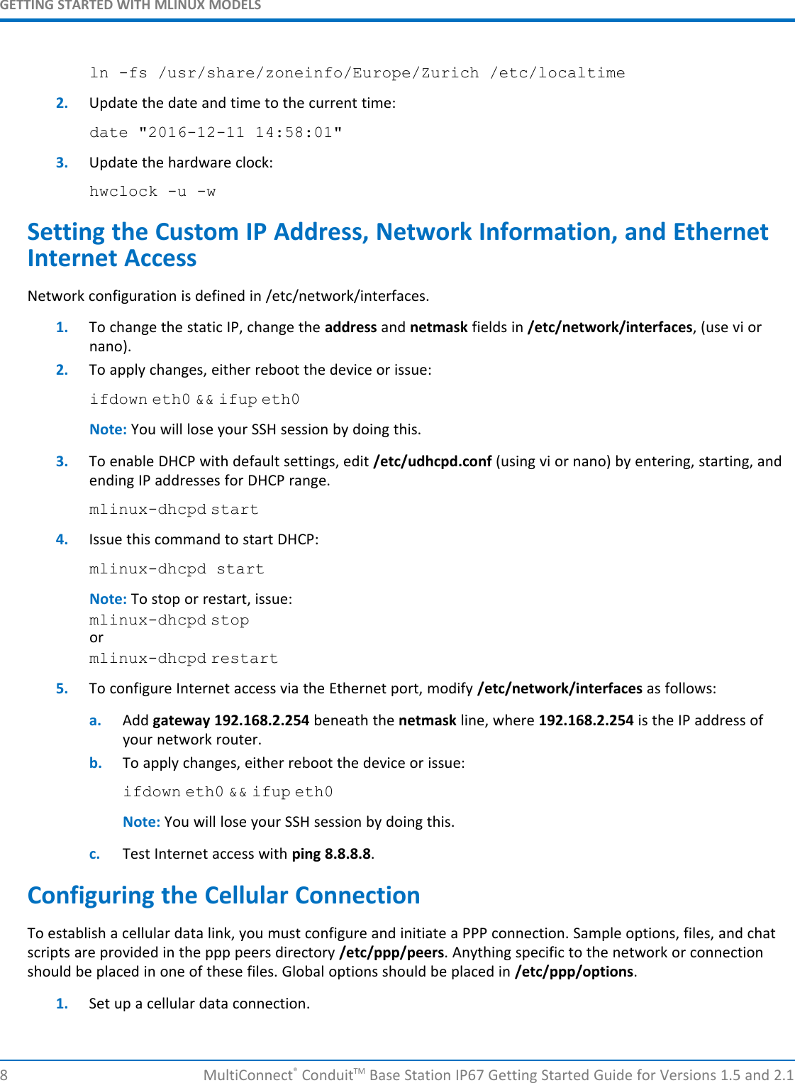
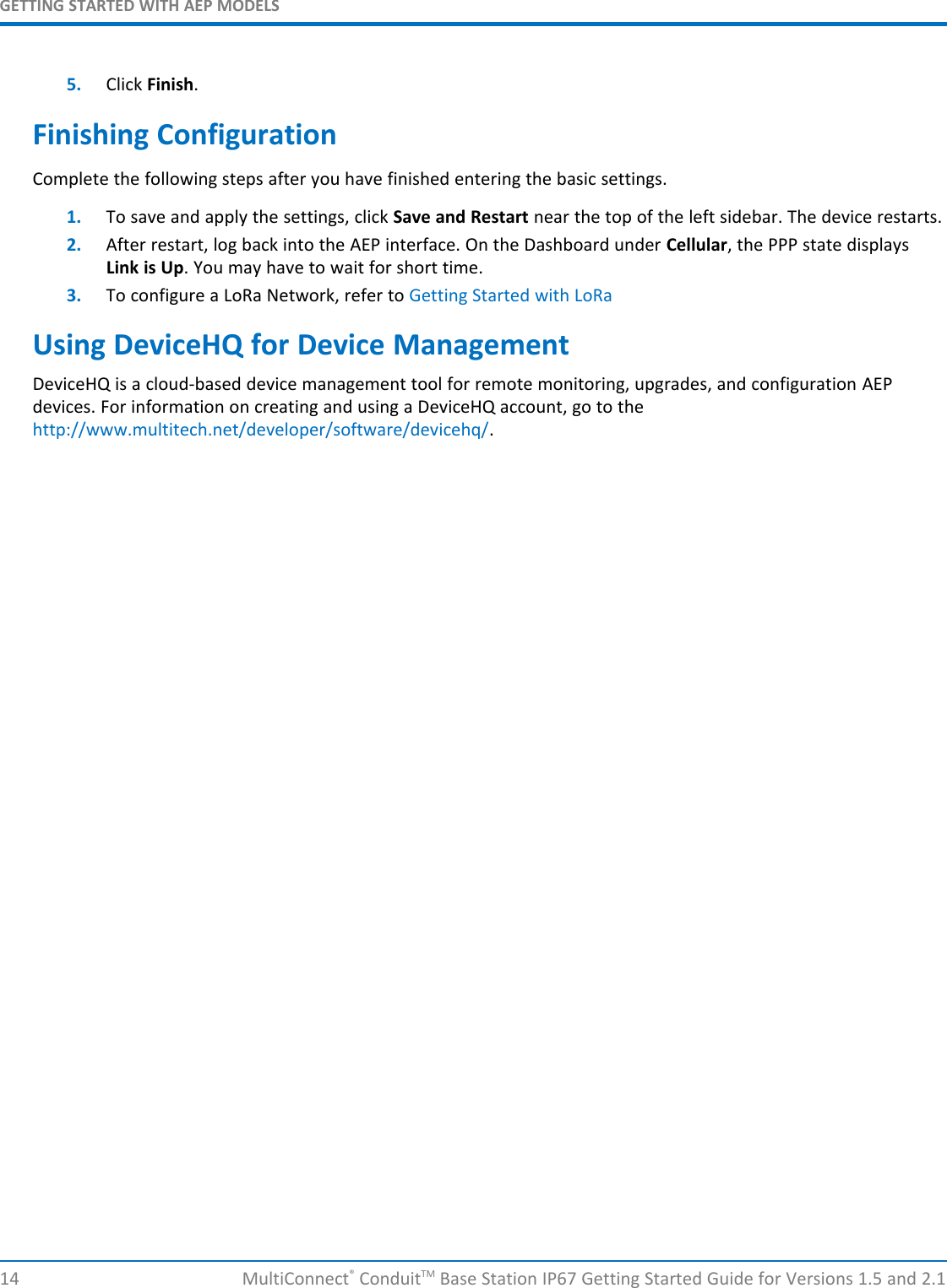
![GETTING STARTED WITH MLINUX MODELSMultiConnect®ConduitTM Base Station IP67 Getting Started Guide for Versions 1.5 and 2.1 7Chapter 2 – Getting Started with mLinux ModelsAccessing the Terminal InterfaceAfter connecting Ethernet and power, access the terminal interface:1. On your PC, configure a static IP address for the network interface that is connected to the device withinthe following range:192.168.2.2 - 192.168.2.2542. Open an SSH connection and log in.Default IP address: (DHCP is disabled)192.168.2.1Default credentials for mLinux version 3: username:rootand password:rootDefault credentials for mLinux version 4: username:mtadmand password:rootNote: The above credentials do NOT have root privileges. As a result, many commands may not work unlessyou use sudo (for super user permissions).To use sudo, either execute :sudo [command]or start the root shell:sudo -sThen enter the mtadm password. The prompt changes to mtcapmtcdtmtcdtip:/home/mtadm#For tips on using sudo, go to http://www.multitech.net/developer/software/mlinux/using-mlinux/log-in-as-an-admin-post-production/.The following commands require sudo:ln -sf /usr/share ...hwclockifdownifupmlinux-set-apnpppdkillall/etc/init.d/lora-packet-forwarderSetting Time Zone, Time, and DateTo set the time zone, date, and time:1. Create a symbolic link from the zone info file for your location to /etc/localtime:](https://usermanual.wiki/Multi-Tech-Systems/92U18H30862/User-Guide-4186559-Page-7.png)
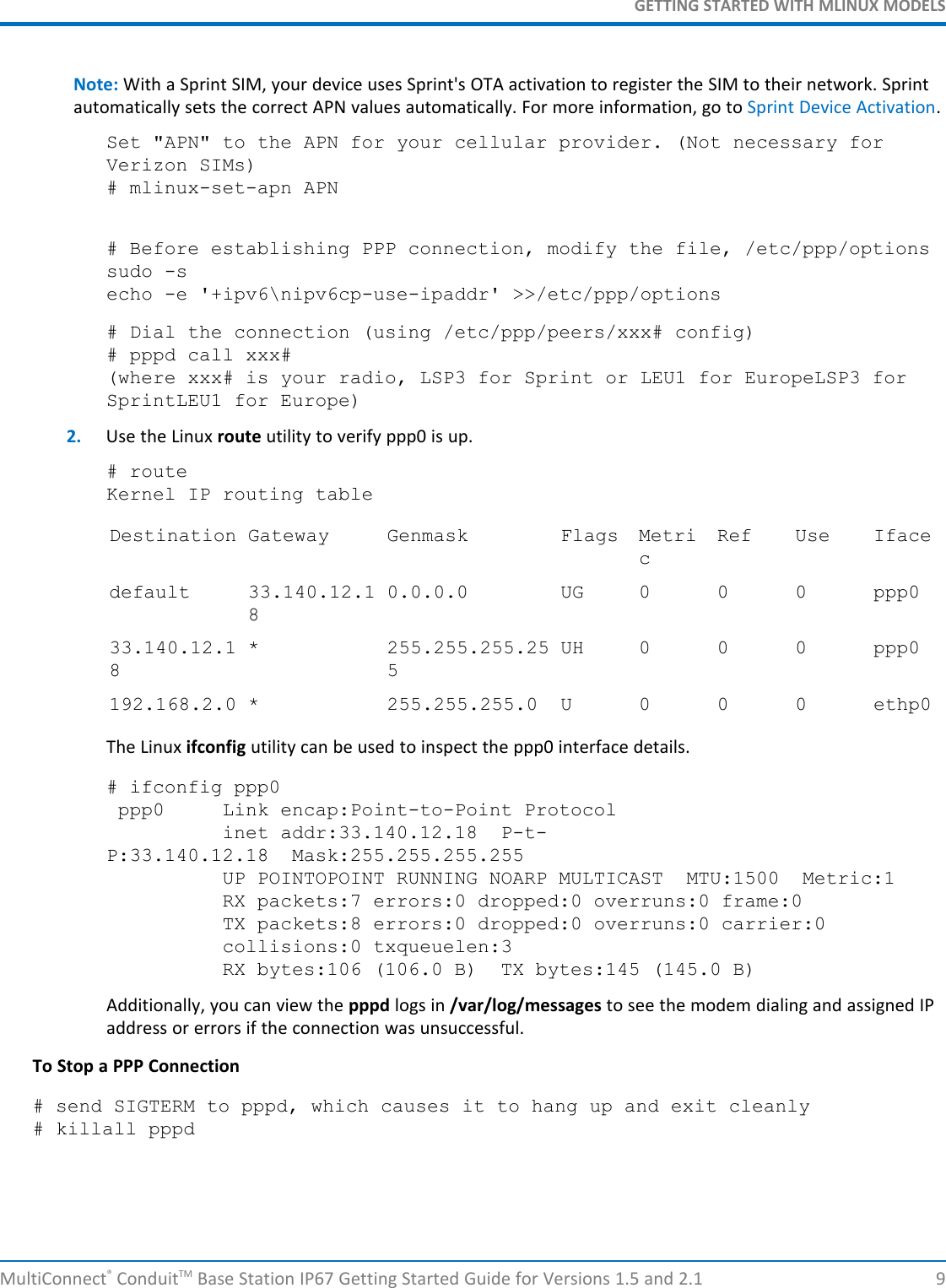
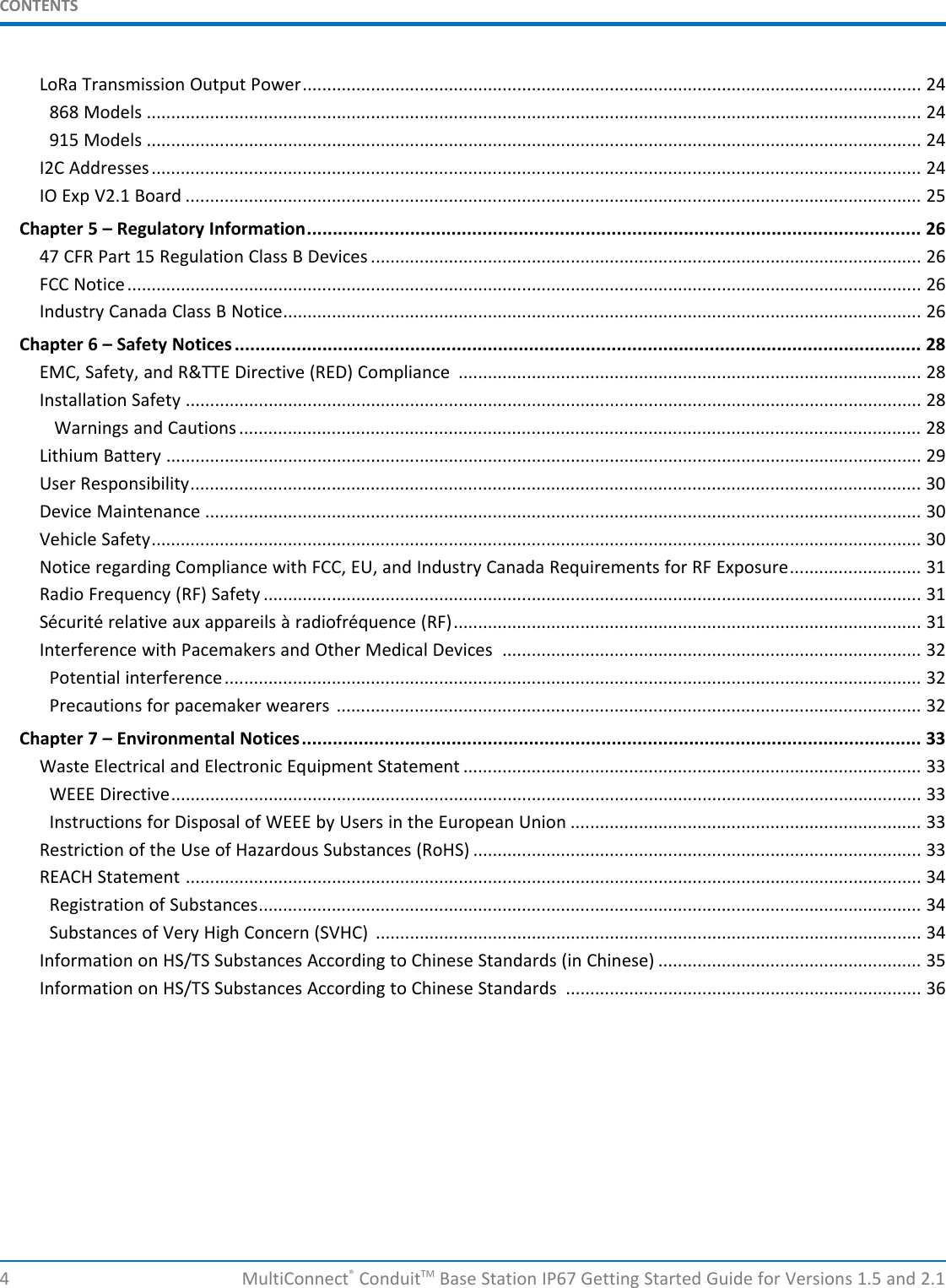
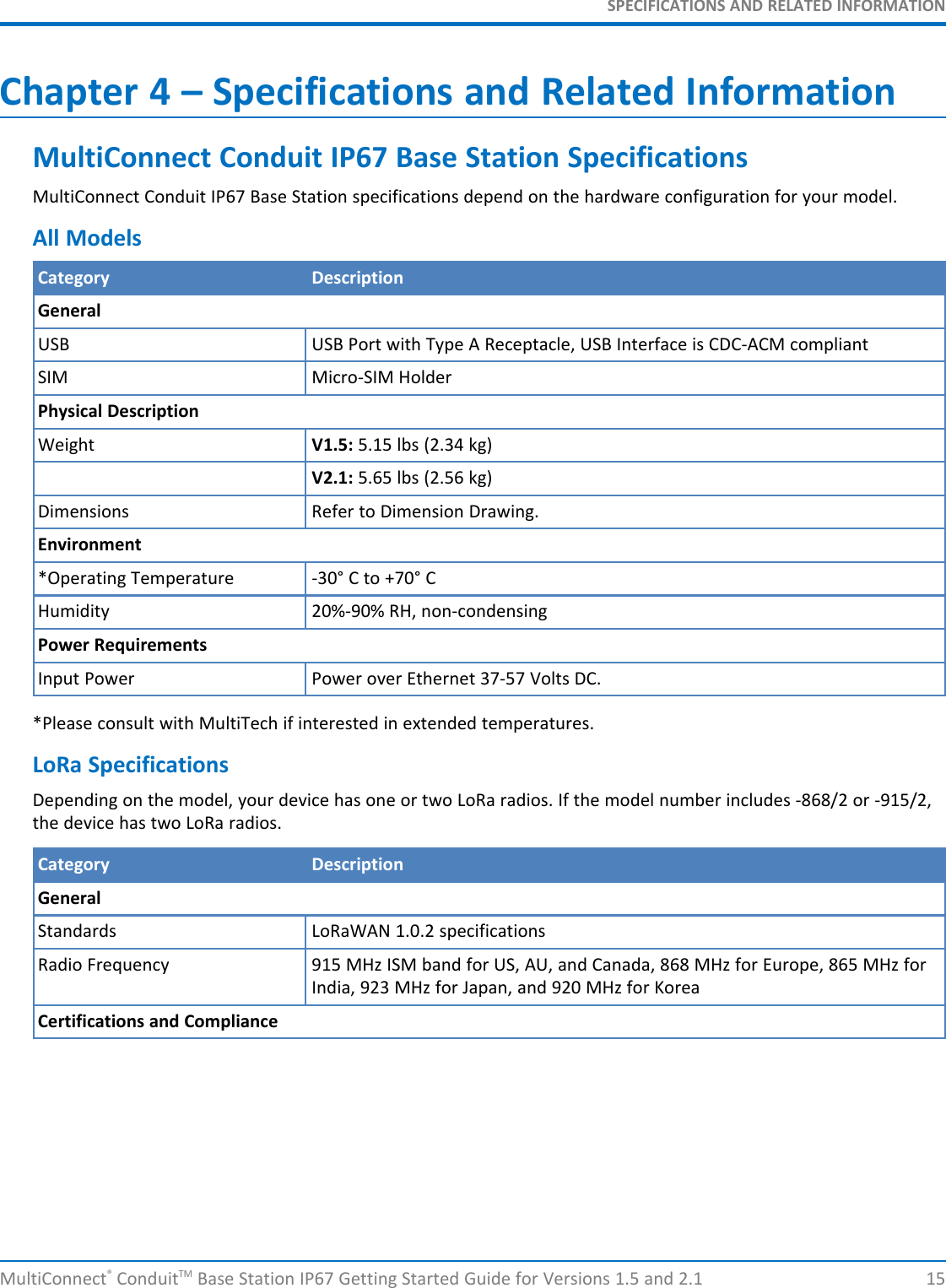
![GETTING STARTED WITH MLINUX MODELS10 MultiConnect®ConduitTM Base Station IP67 Getting Started Guide for Versions 1.5 and 2.1Starting Cellular Connection on BootAutomatically starting pppd on boot requires (1) setting the peer file to use and (2) telling the system to run theppp init script on boot.1. To see the available peers files (leu1) to set the peer file, issue:ls /etc/ppp/peers2. Edit /etc/ppp/ppp_on_boot (with vi or sudo) and change:#PPPD call providerto your desired provider (where xxx# is your radio, LSP3 for Sprint or LEU1 for EuropeLSP3 for SprintLEU1for EuropeLNA3 for North America.)#PPPD call xxx#3. Manually start the init script and check your Internet connection to test your change.ppp_on_boot# /etc/init.d/ppp start4. To set init script to auto start, issue:# update-rc.d ppp defaults5. Restart and test your connection.Stop Automatic Start UpTo stop ppp from automatically starting, issue:# update-rc.d -f ppp removeConfiguring the LoRa Network Server for mLinuxNote: This section applies to LoRaWAN V1.5 devices only.To configure the LoRa Network Server:1. Install the LoRa mCard. Refer to http://www.multitech.net/developer/products/multiconnect-conduit-platform/accessory-cards/installing-an-accessory-card/.2. Attach the LoRa antenna to the LoRa mCard.3. Use the power cable to connect power to the Conduit and wait for the Conduit to boot up.4. Log in to the console. Refer to http://www.multitech.net/developer/software/mlinux/getting-started-with-conduit-mlinux/ if needed.5. Issue these commands:# cp /opt/lora/lora-network-server.conf.sample /var/config/lora/lora-network-server.conf6. Edit /var/config/lora/lora-network-server.conf and modify these settings as needed (use vi or nano).Field LoRa-915 (NA, AU, AS, KR) LoRa-868 (EU, IN)lora["frequencyBand"]: "915" "868"lora["channelplan"]: "US915", "AU915", "AS923", or"KR920""EU868" or "IN865"lora["frequencySubBand"]: (integer. 1 to 8) Not applicable](https://usermanual.wiki/Multi-Tech-Systems/92U18H30862/User-Guide-4186559-Page-10.png)
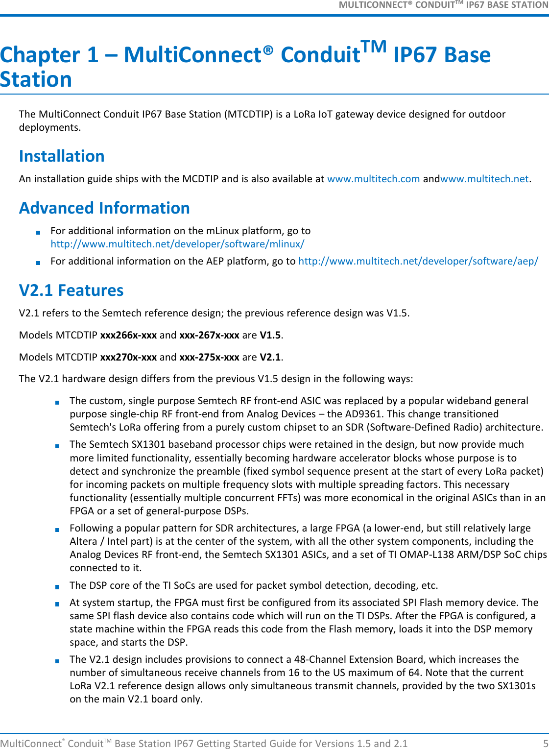
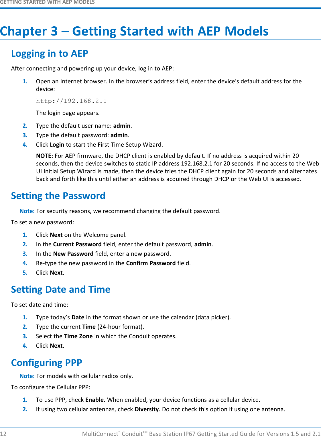
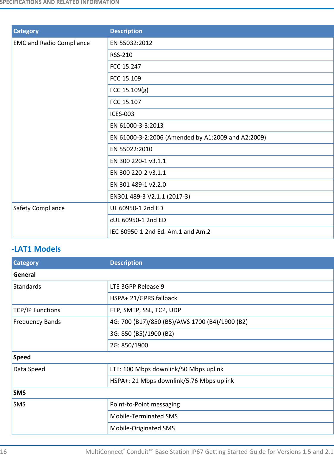
![GETTING STARTED WITH MLINUX MODELSMultiConnect®ConduitTM Base Station IP67 Getting Started Guide for Versions 1.5 and 2.1 11Field LoRa-915 (NA, AU, AS, KR) LoRa-868 (EU, IN)lora["frequencyEU"]: Not Applicable default 869500000range: [863500000 - 867500000] and[869100000 - 869500000]network["name"] Name of your LoRa network (string, 8-character minimum, case-sensitive).network["passphrase"] Security passphrase for your LoRa network (string, 8-character minimum,case-sensitive).network["public"] Choose from 0: Private MTS, 1: Public LoRaWAN or 2: Private LoRaWAN,Private Options use SyncWord 0×12 vs Public SyncWord 0×34.network["joinDelay"]: Set to desired Join Delay, default 5 seconds7. Restart the network server.# /etc/init.d/lora-network-server restart8. Start mosquitto client.# mosquitto_sub -t lora/+/+ -vFor advanced LoRa settings, go to http://www.multitech.net/developer/software/lora/conduit-mlinux-lora-communication/conduit-mlinux-advance-lora-configuration/.Configuring the LoRa Packet Forwarder1. Log in to the console, if you are not logged in.2. Establish an Internet connection via Ethernet or cellular.3. Edit the packet forwarder configuration as necessary by modifying /opt/lora/globallocal_conf.json(version 2.1) or /opt/lora/local_conf.json (version 1.5) with vi or nano.gateway_conf["server_address"] Set your LoRa network server addressgateway_conf["serv_port_up"] Set the up port used by your LoRa network servergateway_conf["serv_port_down"] Set the down port used by your LoRa network server4. Start the packet forwarder:# /etc/init.d/lora-packet-forwarder startAdditional LoRa and mLinux InformationFor additional information, including how to configure LoRa devices to communicate with your gateway, visithttp://www.multitech.net.For help using LoRa, go to: http://www.multitech.net/developer/software/lora/For an introduction to Lora, go to : http://www.multitech.net/developer/software/lora/introduction-to-lora/For getting started with LoRa, go to http://www.multitech.net/developer/software/lora/getting-started-with-lora-conduit-mlinux/For help using mLinux, go to: http://www.multitech.net/developer/software/mlinux/.For additional packet forwarder information, go to:http://www.multitech.net/developer/software/lora/conduit-mlinux-convert-to-basic-packet-forwarder/](https://usermanual.wiki/Multi-Tech-Systems/92U18H30862/User-Guide-4186559-Page-11.png)
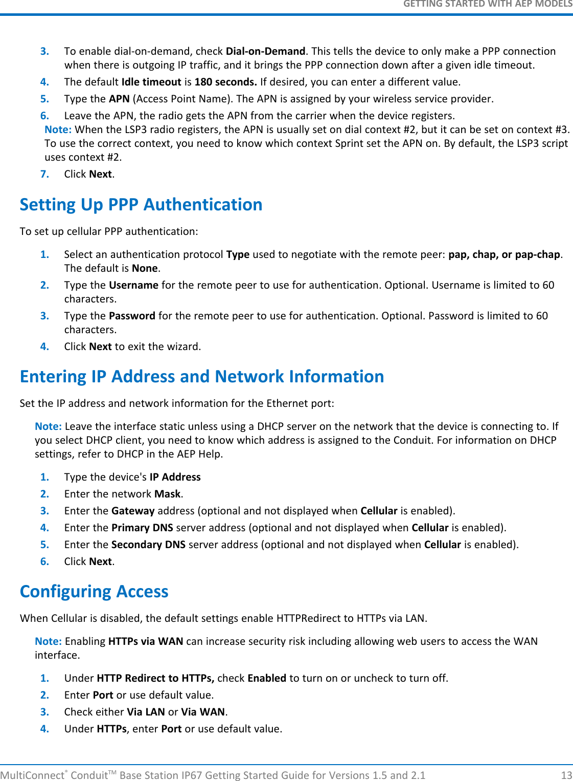
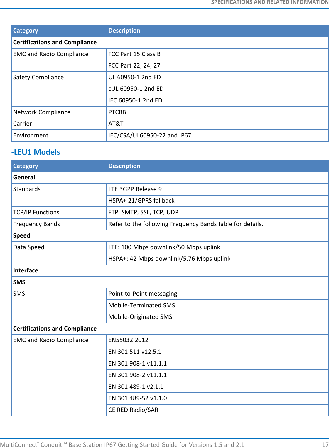
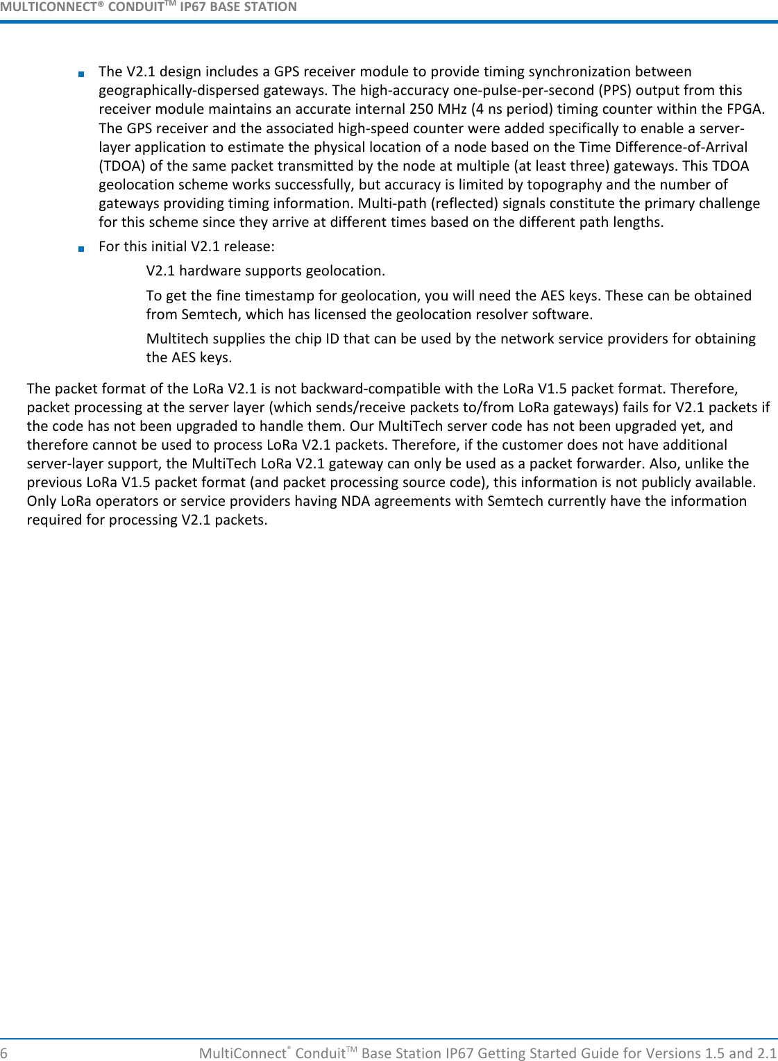
![ENVIRONMENTAL NOTICESMultiConnect®ConduitTM Base Station IP67 Getting Started Guide for Versions 1.5 and 2.1 33Chapter 7 – Environmental NoticesWaste Electrical and Electronic Equipment StatementNote: This statement may be used in documentation for your final product applications.WEEE DirectiveThe WEEE Directive places an obligation on EU-based manufacturers, distributors, retailers, and importers to take-back electronics products at the end of their useful life. A sister directive, ROHS (Restriction of HazardousSubstances) complements the WEEE Directive by banning the presence of specific hazardous substances in theproducts at the design phase. The WEEE Directive covers all MultiTech products imported into the EU as of August13, 2005. EU-based manufacturers, distributors, retailers and importers are obliged to finance the costs of recoveryfrom municipal collection points, reuse, and recycling of specified percentages per the WEEE requirements.Instructions for Disposal of WEEE by Users in the European UnionThe symbol shown below is on the product or on its packaging, which indicates that this product must not bedisposed of with other waste. Instead, it is the user's responsibility to dispose of their waste equipment by handingit over to a designated collection point for the recycling of waste electrical and electronic equipment. The separatecollection and recycling of your waste equipment at the time of disposal will help to conserve natural resourcesand ensure that it is recycled in a manner that protects human health and the environment. For more informationabout where you can drop off your waste equipment for recycling, please contact your local city office, yourhousehold waste disposal service or where you purchased the product.July, 2005Restriction of the Use of Hazardous Substances (RoHS)Multi-Tech Systems, Inc.Certificate of Compliance2011/65/EUMulti-Tech Systems, Inc. confirms that its embedded products comply with the chemical concentration limitationsset forth in the directive 2011/65/EU of the European Parliament (Restriction of the use of certain HazardousSubstances in electrical and electronic equipment - RoHS).These MultiTech products do not contain the following banned chemicals1:Lead, [Pb] < 1000 PPMMercury, [Hg] < 1000 PPM](https://usermanual.wiki/Multi-Tech-Systems/92U18H30862/User-Guide-4186559-Page-33.png)
![ENVIRONMENTAL NOTICES34 MultiConnect®ConduitTM Base Station IP67 Getting Started Guide for Versions 1.5 and 2.1Hexavalent Chromium, [Cr+6] < 1000 PPMCadmium, [Cd] < 100 PPMPolybrominated Biphenyl, [PBB] < 1000 PPMPolybrominated Diphenyl Ether, [PBDE] < 1000 PPMEnvironmental considerations:Moisture Sensitivity Level (MSL) =1Maximum Soldering temperature = 260C (in SMT reflow oven)1Lead usage in some components is exempted by the following RoHS annex, therefore higher lead concentrationwould be found in some modules (>1000 PPM);- Resistors containing lead in a glass or ceramic matrix compound.REACH StatementRegistration of SubstancesAfter careful review of the legislation and specifically the definition of an “article” as defined in EC Regulation1907/2006, Title II, Chapter 1, Article 7.1(a)(b), it is our current view that Multi-Tech Systems, Inc. products wouldbe considered as “articles.” In light of the definition in § 7.1(b) which requires registration of an article only if itcontains a regulated substance that “is intended to be released under normal or reasonably foreseeable conditionsof use,” our analysis is that Multi-Tech Systems, Inc. products constitute nonregisterable articles for their intendedand anticipated use.Substances of Very High Concern (SVHC)Per the candidate list of Substances of Very High Concern (SVHC) published October 28, 2008 we have reviewedthese substances and certify the Multi-Tech Systems, Inc. products are compliant per the EU “REACH”requirements of less than 0.1% (w/w) for each substance. If new SVHC candidates are published by the EuropeanChemicals Agency, and relevant substances have been confirmed to be greater than 0.1% (w/w), Multi-TechSystems, Inc. will provide updated compliance status.Multi-Tech Systems, Inc. also declares it has been duly diligent in ensuring that the products supplied are compliantthrough a formalized process which includes collection and validation of materials declarations and selectivematerials analysis where appropriate. This data is controlled as part of a formal quality system and will be madeavailable upon request.](https://usermanual.wiki/Multi-Tech-Systems/92U18H30862/User-Guide-4186559-Page-34.png)