Multi Tech Systems Modem Mt5634Smi V 34 Users Manual S000263C At Commands
MT5634SMI V.34 to the manual 703d1cd6-75a5-4f52-b1eb-11ecd016aec2
2015-02-09
: Multi-Tech-Systems Multi-Tech-Systems-Multi-Tech-Systems-Modem-Mt5634Smi-V-34-Users-Manual-557999 multi-tech-systems-multi-tech-systems-modem-mt5634smi-v-34-users-manual-557999 multi-tech-systems pdf
Open the PDF directly: View PDF ![]() .
.
Page Count: 136 [warning: Documents this large are best viewed by clicking the View PDF Link!]

SocketModem™
MT5634SMI V.34 & V.92
AT Commands
Fax Class 1 Commands
Fax Class 2 Commands
Voice Commands
Reference Guide

Copyright and Technical Support
Multi-Tech Systems, Inc. SocketModem MT5634SMIxx Reference Guide (S000263C) 2
SocketModem Reference Guide
Serial: MT5634SMI-34, MT5634SMI-92
Parallel: MT5634SMI-P-92
Medical Device: MT5634SMI-HV-92, MT5634SMI-P-HV-92
Industrial Temperature: MT5634SMI-ITP-92, MT5634SMI-P-ITP-92
PN S000263C, Version C
Copyright
This publication may not be reproduced, in whole or in part, without prior expressed written
permission from Multi-Tech Systems, Inc. All rights reserved.
Copyright © 2003-4, by Multi-Tech Systems, Inc.
Multi-Tech Systems, Inc. makes no representations or warranties with respect to the contents hereof
and specifically disclaim any implied warranties of merchantability or fitness for any particular
purpose. Furthermore, Multi-Tech Systems, Inc. reserves the right to revise this publication and to
make changes from time to time in the content hereof without obligation of Multi-Tech Systems, Inc.
to notify any person or organization of such revisions or changes.
Revisions
Revision Level Date Description
A 08/09/02 First release. Includes global configuration and V.92 protocol.
B 06/27/03 Add V.34 documentation. Updated the Serial Test/Demo Board graphic.
Updated the parts list. Updated Flash Programming Protocol. Updated
Telecom Approvals and Country Codes. Changed the product name
from ModemModule to SocketModem.
C 06/04/04 Create a separate Universal Socket Hardware guide and a separate AT
Command Reference Guide.
Trademarks
Trademarks of Multi-Tech Systems, Inc. are SocketModem and the Multi-Tech logo.
Microsoft and Microsoft Windows are either registered trademarks or trademarks of Microsoft
Corporation in the United States and/or other countries.
World Headquarters
Multi-Tech Systems, Inc.
2205 Woodale Drive
Mounds View, MN 55112
Phone: 763-785-3500 or 800-328-9717
Fax: 763-785-9874
Technical Support
Country By Email By Phone
France: support@multitech.fr (33) 1-64 61 09 81
India: support@multitechindia.com 91 (124) 6340778
U.K.: support@multitech.co.uk (44) 118 959 7774
U.S. and Canada: oemsales@multitech.com (800) 972-2439
Rest of the World: oemsales@multitech.com (763) 717-5863
Internet Address: http://www.multitech.com

Table of Contents
Multi-Tech Systems, Inc. SocketModem MT5634SMIxx Reference Guide (S000263C) 3
Contents
Chapter 1 – AT Commands, S-Registers and Result Codes ..................................................................5
Introduction ................................................................................................................................................5
AT Command Summary ............................................................................................................................6
AT Commands...........................................................................................................................................8
Escape AT Commands............................................................................................................................21
V.92 Commands ......................................................................................................................................22
S-Registers ..............................................................................................................................................28
Result Codes ...........................................................................................................................................31
Chapter 2 – Fax Class 1 and Class 1.0 Commands...............................................................................33
Fax I/O Processing ..................................................................................................................................33
DTE-to-Modem Transmit Data Stream ...............................................................................................33
Modem-to-DTE Receive Data Stream ................................................................................................33
Fax Mode Selection.............................................................................................................................34
Fax Origination....................................................................................................................................34
Fax Answering.....................................................................................................................................34
Fax Control Transmission ...................................................................................................................34
Fax Control Reception.........................................................................................................................35
Fax Data Transmission .......................................................................................................................36
Fax Data Reception.............................................................................................................................36
Commands and Parameters....................................................................................................................37
Mode Entry Commands.......................................................................................................................37
Mode Commands................................................................................................................................37
Service Class 1 Commands ....................................................................................................................41
Examples .................................................................................................................................................45
Chapter 3 – Fax Class 2 and 2.0/2.1 Commands ...................................................................................48
Introduction ..............................................................................................................................................48
AT Command Implementation .................................................................................................................49
Modes of Interaction ................................................................................................................................50
AT Command Mode ............................................................................................................................50
Command Execution Mode.................................................................................................................52
Data Transfer Mode ............................................................................................................................52
Commands and Responses Overview ....................................................................................................55
Action Commands...............................................................................................................................55
Modem Responses .............................................................................................................................56
Parameters for Mandatory Services....................................................................................................57
Parameters for Optional Services .......................................................................................................58
Identification Commands .........................................................................................................................59
Service Class Indication......................................................................................................................59
Service Class Capabilities...................................................................................................................59
Service Class Selection.......................................................................................................................60
Request Manufacturer Identification ...................................................................................................60
Request Model Identification...............................................................................................................60
Request Revision Identification...........................................................................................................60
Action Commands....................................................................................................................................61
Originate a Call....................................................................................................................................61
Answer a Call ......................................................................................................................................61
Data Transmission ..............................................................................................................................62
Post-Page Message Release..............................................................................................................62
Data Reception....................................................................................................................................63
Session Termination............................................................................................................................63
Initialize Facsimile Parameters ...........................................................................................................63
Modem Responses..................................................................................................................................64
T.30 Phase A Negotiation Responses ................................................................................................64

Table of Contents
Multi-Tech Systems, Inc. SocketModem MT5634SMIxx Reference Guide (S000263C) 4
T.30 Phase B Negotiation Responses ................................................................................................65
T.30 Phase C Page Reception Responses.........................................................................................68
T.30 Phase D Post Page Responses..................................................................................................69
Call Termination with Status................................................................................................................69
Parameter Commands.............................................................................................................................72
T.30 Session Parameters....................................................................................................................72
T.30 Procedure Control Parameters ...................................................................................................82
Phase C Data Format Parameters......................................................................................................87
Miscellaneous Parameters..................................................................................................................92
Session Message Report Responses......................................................................................................93
Sample Modem Control Sessions ...........................................................................................................94
Send two pages, 1-D data, no errors (Class 2)...................................................................................94
Receive two pages, 1-D data, no errors (Class 2)..............................................................................95
Send two pages, 1-D data, no errors (Class 2.0)................................................................................96
Receive two pages, 1-D data, no errors (Class 2.0)...........................................................................97
Originate and send a two page facsimile with V.34 half-duplex (Class 2.1).......................................98
Answer and receive a two-page facsimile with V.34 half-duplex (Class 2.1)......................................99
Alphabetic List of Commands and Responses......................................................................................100
ASCII Conversion Chart.........................................................................................................................102
Chapter 4 – Voice Commands ...............................................................................................................103
Introduction ............................................................................................................................................103
Voice S-Register Summary ...................................................................................................................104
Voice Commands...................................................................................................................................104
Commands That Change for Voice Mode Support................................................................................104
Voice +V Commands Summary.............................................................................................................105
Voice +V Commands Detail...................................................................................................................105
Interface Configuration Commands.......................................................................................................119
Flow Control...........................................................................................................................................121
Voice Mode Result Codes .....................................................................................................................121
Unsolicited Voice Mode Result Codes...................................................................................................122
Valid Complex Event Report Tags....................................................................................................122
Voice Mode Shielded Codes .................................................................................................................123
Sample Sessions ...................................................................................................................................125
Sample Rate Selection and Suggested Compression Method.........................................................125
Answer Phone, Play Greeting Message, and Record Message Example........................................126
DTE/DCE Interface Rates......................................................................................................................128
Chapter 5 – Remote Configuration and Country Code Configuration ..............................................129
Remote Configuration............................................................................................................................129
Basic Procedure................................................................................................................................129
Setup .................................................................................................................................................129
Country Code Configuration ..................................................................................................................130
Using the Global Wizard Utility..........................................................................................................130
Using AT Commands ........................................................................................................................130
Index.........................................................................................................................................................131

Chapter 1 – AT Commands, S-Registers and Result Codes
Multi-Tech Systems, Inc. SocketModem MT5634SMIxx Reference Guide (S000263C) 5
Chapter 1 – AT Commands, S-
Registers and Result Codes
Introduction
The AT commands are used to control the operation of your modem. They are called AT commands
because the characters AT must precede each command to get the ATtention of the modem.
AT commands can be issued only when the modem is in command mode or online command mode.
• The modem is in command mode whenever it is not connected to another modem.
• The modem is in data mode whenever it is connected to another modem and ready to exchange
data. Online command mode is a temporary state in which you can issue commands to the
modem while connected to another modem.
• To put the modem into online command mode from data mode, you must issue an escape
sequence (+++) followed immediately by the AT characters and the command, e.g., +++ATH to
hang up the modem. To return to data mode from online command mode, you must issue the
command ATO.
To send AT commands to the modem you must use a communications program, such as the
HyperTerminal applet in Windows 98 and NT 4.0, or some other available terminal program. You can
issue commands to the modem either directly, by typing them in the terminal window of the
communications program, or indirectly, by configuring the operating system or communications
program to send the commands automatically. Fortunately, communications programs make daily
operation of modems effortless by hiding the commands from the user. Most users, therefore, need to
use AT commands only when reconfiguring the modem, e.g., to turn auto answer on or off.
The format for entering an AT command is ATXn, where X is the command and n is the specific value
for the command, sometimes called the command parameter. The value is always a number. If the
value is zero, you can omit it from the command; thus, AT&W is equivalent to AT&W0. Most
commands have a default value, which is the value that is set at the factory. The default values are
shown in the “AT Command Summary” (See below).
You must press ENTER (it could be some other key depending on the terminal program) to send the
command to the modem. Any time the modem receives a command, it sends a response known as a
result code. The most common result codes are OK, ERROR, and the CONNECT messages that the
modem sends to the computer when it is connecting to another modem. See a table of valid result
codes at the end of this chapter.
You can issue several commands in one line, in what is called a command string. The command
string begins with AT and ends when you press ENTER. Spaces to separate the commands are
optional; the command interpreter ignores them. The most familiar command string is the initialization
string, which is used to configure the modem when it is turned on or reset, or when your
communications software calls another modem.

Chapter 1 – AT Commands, S-Registers and Result Codes
Multi-Tech Systems, Inc. SocketModem MT5634SMIxx Reference Guide (S000263C) 6
AT Command Summary
Organization of AT Commands on the following pages: 1st, by the initial command character (&, +, %)
2nd, alphabetized by the second command character (Except for listing of AT).
Command Description
AT Attention Code
A Answer
A/ Repeat Last Command
Bn Communication Standard Setting
Ds Dial
DS=y Dial Stored Telephone Number
En Echo Command Mode Characters
Fn Echo Online Data Characters
Hn Hook Control
In Information Request
Mn Monitor Speaker Mode
Nn Modulation Handshake
On Return Online to Data Mode
P Pulse Dialing
Qn Result Codes Enable/Disable
Sr=n Set Register Value
Sr? Read Register Value
T Tone Dialing
Vn Result Code Format
Wn Result Code Options
Xn Result Code Selection
Zn Modem Reset
&Cn Data Carrier Detect (DCD) Control
&Dn Data Terminal Ready (DTR) Control
&En XON/XOFF Pass-Through
&Fn Load Factory Settings
&Gn V.22bis Guard Tone Control
&Kn Flow Control Selection
&Ln Leased Line Operation
&Pn Pulse Dial Make-to-Break Ratio Selection
&Qn Asynchronous Communications Mode
&Sn Data Set Ready (DSR) Control
&Tn Loopback Test (V.54 Test) Commands
&V Display Current Settings
&Wn Store Current Configuration
&Zy=x Store Dialing Command
\An Select Maximum MNP Block Size
\Bn Transmit Break
\Kn Break Control
\Nn Error Correction Mode Selection
\Qn Flow Control Selection
\Tn Inactivity Timer
\Vn Protocol Result Code
-Cn Data Calling Tone
%A Adaptive Answer Result Code Enable
%B View Numbers in Blacklist
%Cn Data Compression Control
%DCn AT Command Control
%En Fallback and Fall Forward Control
%Hn Direct Connect Enable
%Rn Cisco Configuration
%Sn Command Speed Response
$EBn Asynchronous Word Length

Chapter 1 – AT Commands, S-Registers and Result Codes
Multi-Tech Systems, Inc. SocketModem MT5634SMIxx Reference Guide (S000263C) 7
Command Description
$Dn DTR Dialing
$MBn Online BPS Speed
$SBn Serial Port Baud Rate
#CBAn Callback Attempts
#CBDn Callback Delay
# CBF? Callback Failed Attempts Display
# CBFR Callback Failed Attempts Reset
# CBIn Local Callback Inactivity Timer
# CBNy=n Store Callback Password
# CBPn Callback Parity
# CBRy Callback Security Reset
# CBSn Callback Enable/Disable
#Pn Set 11-bit Parity
#Sx Enter Setup Password
#S=x Store Setup Password
+VDR=x, y Distinctive Ring Report
+++AT<CR> Escape Sequence
%%%ATMTSMODEM<CR> Remote Configuration Escape Sequence
V.92 Commands

Chapter 1 – AT Commands, S-Registers and Result Codes
Multi-Tech Systems, Inc. SocketModem MT5634SMIxx Reference Guide (S000263C) 8
AT Commands
Command: AT Attention Code
Values: N/A
Description: The attention code precedes all command lines except A/, A: and escape
sequences.
Command: ENTER Key
Values: N/A
Description: Press the ENTER (RETURN) key to execute most commands.
Command: A Answer
Values: N/A
Description: Answer call before final ring.
Command: A/ Repeat Last Command
Values: N/A
Description: Repeat the last command string. Do not precede this command with AT. Do not
press ENTER to execute.
Command: Bn Communication Standard Setting
Values: n = 0–3, 15, 16
Default: 0 and 15
Description: B0 Select ITU-T V.22 mode when modem is at 1200 bps.
B1 Select Bell 212A when modem is at 1200 bps.
B2 Deselect V.23 reverse channel (same as B3).
B3 Deselect V.23 reverse channel (same as B2).
B15 Select V.21 when the modem is at 300 bps.
B16 Select Bell 103J when the modem is at 300 bps.

Chapter 1 – AT Commands, S-Registers and Result Codes
Multi-Tech Systems, Inc. SocketModem MT5634SMIxx Reference Guide (S000263C) 9
Command: Ds Dial
Values: s = dial string (phone number and dial modifiers)
Default: none
Description: Dial telephone number s, where s may up to 40 characters long and include the 0–
9, *, #, , B, C, and D characters, and the L, P, T, V, W, S, comma (,), semicolon (;),
!, @, ^ and $ dial string modifiers.
Dial string modifiers:
L Redial last number. (Must be placed immediately after ATD.)
P Pulse-dial following numbers in command.
T Tone-dial following numbers in command (default).
V Switch to speakerphone mode and dial the following number. Use ATH
command to hang up.
W Wait for a new dial tone before continuing to dial. (X2, X4, X5, X6, or X7 must
be selected.)
, Pause during dialing for time set in register S8.
; Return to command mode after dialing. (Place at end of dial string.)
! Hook flash. Causes the modem to go on-hook for one-half second, then off-
hook again.
@ Wait for quiet answer. Causes modem to wait for a ringback, then 5 seconds
of silence, before processing next part of command. If silence is not detected,
the modem returns a NO ANSWER code.
^ Disable data calling tone transmission.
$ Detect AT&T call card “bong” tone. The character should follow the phone
number and precede the user’s call card number:
ATDT1028806127853500$123456789
Command: DS=y Dial Stored Telephone Number
Values: n = 0–2 (0–1 for SMI-Parallel {internal})
Default: none
Description: Dial a number previously stored in directory number y by the &Zy=x command.
Example: ATDS=2
Command: En Echo Command Mode Characters
Values: n = 0 or 1
Default: 1
Description: E0 Do not echo keyboard input to the terminal.
E1 Do echo keyboard input to the terminal.
Command: Fn Echo Online Data Characters
Values: n = 1
Default: 1
F0 Enable online data character echo. (Not supported.)
F1 Disable online data character echo (included for backward compatibility with
some software).
Command: Hn Hook Control
Values: n = 0 or 1
Default: 0
Description: H0 Go on-hook (hang up).
H1 Go off-hook (make the phone line busy).

Chapter 1 – AT Commands, S-Registers and Result Codes
Multi-Tech Systems, Inc. SocketModem MT5634SMIxx Reference Guide (S000263C) 10
Command: In Information Request
Values: n = 0–5, 9, 11
Default: None
Description: I0 Display default speed and controller firmware version.
I1 Calculate and display ROM checksum (e.g., 12AB).
I2 Check ROM and verify the checksum, displaying OK or ERROR.
I3 Display default speed and controller firmware version.
I4 Display firmware version for data pump (e.g., 94).
I5 Display the board ID: software version, hardware version, and country ID
I9 Display the country code (e.g., NA Ver. 1).
I11 Display diagnostic information for the last modem connection, such as DSP
and firmware version, link type, line speed, serial speed, type of error
correction/data compression, number of past retrains, etc.
Command: Mn Monitor Speaker Mode
Values: n = 0, 1, 2, or 3
Default: 1
Description: M0 Speaker always off.
M1 Speaker on until carrier signal detected.
M2 Speaker always on when modem is off-hook.
M3 Speaker on until carrier is detected, except while dialing.
Command: Nn Modulation Handshake
Values: n = 0 or 1
Default: 1
Description: N0 Modem performs handshake only at communication standard specified by
S37 and the B command.
N1 Modem begins handshake at communication standard specified by S37 and
the B command. During handshake, fallback to a lower speed can occur.
Command: On Return Online to Data Mode
Values: 0, 1, 3
Default: None
Description: O0 Exit online command mode and return to data mode (see +++AT<CR>
escape sequence).
O1 Issue a retrain and return to online data mode.
O3 Issue a rate renegotiations and return to data mode.
Command: P Pulse Dialing
Values: P, T
Default: T
Description: Configures the modem for pulse (non-touch-tone) dialing. Dialed digits are pulsed
until a T command or dial modifier is received.
Command: Qn Result Codes Enable/Disable
Values: n = 0 or 1
Default: 0
Description: Q0 Enable result codes.
Q1 Disable result codes.
Q2 Returns an OK for backward compatibility with some software.

Chapter 1 – AT Commands, S-Registers and Result Codes
Multi-Tech Systems, Inc. SocketModem MT5634SMIxx Reference Guide (S000263C) 11
Command: Sr=n Set Register Value
Values: r = S-register number; n varies
Default: None
Description: Set value of register Sr to value of n, where n is entered in decimal format (e.g.,
S0=1).
Command: Sr? Read Register Value
Values: r = S-register number
Default: None
Description: Read value of register Sr and display it in 3-digit decimal form (e.g., S2? gives the
response 043).
Command: T Tone Dialing
Values: P, T
Default: T
Description: Configures the modem for DTMF (touch-tone) dialing. Dialed digits are tone dialed
until a P command or dial modifier is received.
Command: Vn Result Code Format
Values: n = 0 or 1
Default: 1
Description: V0 Displays result codes as digits (terse response).
V1 Displays result codes as words (verbose response).
Command: Wn Result Code Options
Values: n = 0, 1, or 2
Default: 2
Description: W0 CONNECT result code reports serial port speed, disables protocol result
codes.
W1 CONNECT result code reports serial port speed, enables protocol result
codes.
W2 CONNECT result code reports line speed, enables protocol result codes.
Command: Xn Result Code Selection
Values: n = 0–7
Default: 4
Description: X0 Basic result codes (CONNECT); does not look for dial tone or busy signal.
X1 Extended result codes (CONNECT 46000 V42bis); does not look for dial tone
or busy signal.
X2 Extended result codes with NO DIALTONE; does not look for busy signal.
X3 Extended result codes with BUSY; does not look for dial tone.
X4 Extended result codes with NO DIALTONE and BUSY.
X5 Extended result codes with NO DIALTONE and BUSY.
X6 Extended result codes with NO DIALTONE and BUSY.
X7 Basic result codes with NO DIALTONE and BUSY.
Command: Zn Modem Reset
Values: n = 0 or 1
Default: None
Description: Z0 Reset modem to profile saved by the last &W command.
Z1 Same as Z0.

Chapter 1 – AT Commands, S-Registers and Result Codes
Multi-Tech Systems, Inc. SocketModem MT5634SMIxx Reference Guide (S000263C) 12
Command: &Cn Data Carrier Detect (DCD) Control
Values: n = 0, 1, 2
Default: 1
Description: &C0 Forces the DCD circuit to be always ON.
&C1 DCD goes ON when the remote modem’s carrier signal is detected, and
goes OFF when the carrier signal is not detected.
&C2 DCD turns OFF upon disconnect for time set by S18. It then goes high again
(for some PBX phone systems).
Command: &Dn Data Terminal Ready (DTR) Control
Values: n = 0, 1, 2, or 3
Default: 2
Description: &D0 Modem ignores true status of DTR signal and responds as if it is always on.
&D1 If DTR drops while in online data mode, the modem enters command mode,
issues an OK, and remains connected.
&D2 If DTR drops while in online data mode, the modem hangs up. If the signal is
not present, the modem will not answer or dial.
&D3 If DTR drops, modem hangs up and resets as if ATZ command were issued.
Command: &En XON/XOFF Pacing Control
Values: n = 12 or 13
Default: 12
Description: &E12 Disables XON/XOFF pacing.
&E13 Enables XON/XOFF pacing.
Command: &Fn Load Factory Settings
Values: n = 0
Default: None
Description: &F0 Load factory settings as active configuration.
Note: See also the Z command.
Command: &Gn V.22bis Guard Tone Control
Values: n = 0, 1, or 2
Default: 0
Description: &G0 Disable guard tone.
&G1 Set guard tone to 550 Hz.
&G2 Set guard tone to 1800 Hz.
Note: The &G command is not used in North America.
Command: &Kn Flow Control Selection
Values: n = 0, 3, or 4
Defaults: 3
Description: &K0 Disable flow control.
&K3 Enable CTS/RTS hardware flow control.
&K4 Enable XON/XOFF software flow control.

Chapter 1 – AT Commands, S-Registers and Result Codes
Multi-Tech Systems, Inc. SocketModem MT5634SMIxx Reference Guide (S000263C) 13
Command: &Ln Leased Line Operation
Values: n = 0, 1, or 2
Defaults: 0
Description: &L0 The modem is set for standard dial-up operation.
&L1 The modem is set for leased line operation in originate mode.
&L2 The modem is set for leased line operation in answer mode.
Note: For &L1 and &L2, there is a 30-second window between power up and the
starting of the leased line handshake. During this time, you can turn off the
command, if desired.
Command: &Pn Pulse Dial Make-to-Break Ratio Selection
Values: n = 0, 1, or 2
Default: 0
Description: &P0 60/40 make-to-break ratio
&P1 67/33 make-to-break ratio
&P2 20 pulses per second
Note: The &P2 command is available only if the country code is set to Japan.
Command: &Qn Asynchronous Communications Mode
Values: n = 0, 5, 6, 8, or 9
Default: 5
Description: &Q0 Asynchronous with data buffering. Same as \N0.
&Q5 Error control with data buffering. Same as \N3.
&Q6 Asynchronous with data buffering. Same as \N0.
&Q8 MNP error control mode. If MNP error control is not established, the modem
falls back according to the setting in S36.
&Q9 V.42 or MNP error control mode. If neither error control is established, the
modem falls back according to the setting in S36.
Command: &Sn Data Set Ready (DSR) Control
Values: n = 0 or 1
Default: 0
Description: &S0 DSR is always ON.
&S1 DSR goes ON only during a connection.
Command: &Tn Loopback Test (V.54 Test) Commands Values: n = 0, 1, 3, 6
Default: None
Description: The modem can perform selected test and diagnostic functions. A test can be run
only when the modem is operating in non-error-correction mode (normal or direct
mode). For tests 3 and 6, a connection between the two modems must be
established. To terminate a test in progress, the escape sequence (+++AT) must
be entered.
&T0 Stops any test in progress.
&T1 Starts a local analog loopback, V.54 Loop 3, test. If a connection exists when
this command is issued, the modem hangs up. When the test starts, a
CONNECT message is displayed.
&T3 Starts local digital loopback, V.54 Loop 2, test. If no connection exists,
ERROR is returned.
&T6 Initiates a remote digital loopback, V.54 Loop 2, test without self-test. If no
connection exists, ERROR is returned.

Chapter 1 – AT Commands, S-Registers and Result Codes
Multi-Tech Systems, Inc. SocketModem MT5634SMIxx Reference Guide (S000263C) 14
Command: &V Display Current Settings
Values: N/A
Description: Displays the active modem settings.
Command: &Wn Store Current Configuration
Values: n = 0 or 1
Default: 1
Description: &W0 Stores current modem settings in non-volatile memory and causes them to
be loaded at power-on or following the ATZ command instead of the
factory defaults. See &F command.
&W1 Clears user default settings from non-volatile memory and causes the
factory defaults to be loaded at power-on or following the ATZ command.
Command: &Zy=x Store Dialing Command
Values: y = 0–2 (0–1SMI-Parallel {internal})
x = Dialing command
Default: None
Description: Stores dialing command x in memory location y. Dial the stored number using the
command ATDS=y. See Also the #CBS command, a callback security command.
Command: \An Select Maximum MNP Block Size
Values: n = 0, 1, 2, or 3
Default: 3
Description: \A0 64-character maximum
\A1 128-character maximum
\A2 192-character maximum
\A3 256-character maximum
Command: \Bn Transmit Break
Values: n = 0–9 in 100 ms units
Default: 3
Description: In non-error-correction mode only, sends a break signal of the specified length to a
remote modem. Works in conjunction with the \K command.

Chapter 1 – AT Commands, S-Registers and Result Codes
Multi-Tech Systems, Inc. SocketModem MT5634SMIxx Reference Guide (S000263C) 15
Command: \Kn Break Control
Values: n = 0–5
Default: 5
Description: Controls the modem's response to a break received from: computer, remote
modem, or \B command. Response is different for each of three different states.
Data mode. Modem receives the break from the computer:
\K0 Enter online command mode, no break sent to the remote modem.
\K1 Clear data buffers and send break to the remote modem.
\K2 Same as \K0.
\K3 Send break immediately to the remote modem.
\K4 Same as \K0.
\K5 Send break to the remote modem in sequence with the transmitted data.
Data mode. Modem receives the break from the remote modem:
\K0 Clear data buffers and send break to the computer.
\K1 Same as \K0.
\K2 Send break immediately to the computer.
\K3 Same as \K2.
\K4 Send break to the computer in sequence with the received data.
\K5 Same as \K4.
Online command mode. Modem receives a \Bn command from the computer:
\K0 Clear data buffers and send break to the remote modem.
\K1 Same as \K0.
\K2 Send break immediately to the remote modem.
\K3 Same as \K2.
\K4 Send break to the remote modem in sequence with the transmitted data.
\K5 Same as \K4.
Command: \Nn Error Correction Mode Selection
Values: n = 0–5, or 7
Default: 3
Description: \N0 Non-error correction mode with data buffering (buffer mode; same as &Q6).
\N1 Direct mode.
\N2 MNP reliable mode. If the modem cannot make an MNP connection, it
disconnects.
\N3 V.42/MNP auto-reliable mode. The modem attempts first to connect in V.42
error correction mode, then in MNP mode, and finally in non-error correction
(buffer) mode with continued operation.
\N4 V.42 reliable mode. If the modem cannot make a V.42 connection, it
disconnects.
\N5 V.42, MNP, or non-error correction (same as \ N3).
\N7 V.42, MNP, or non-error correction (same as \ N3).
Command: \Qn Flow Control Selection
Values: n = 0, 1, or 3
Default: 3
Description: \Q0 Disable flow control (same as &K0).
\Q1 XON/XOFF software flow control (same as &K4).
\Q2 CTS-only flow control. Not supported.
\Q3 RTS/CTS hardware flow control (same as &K3).
Command: \Tn Inactivity Timer
Values: n = 0, 1–255
Default: 0
Description: Sets the time (in minutes) after the last character is sent or received that the
modem waits before disconnecting. A value of zero disables the timer. Applies only
in buffer mode.
Note: You can also set the inactivity timer by changing the value of S30.

Chapter 1 – AT Commands, S-Registers and Result Codes
Multi-Tech Systems, Inc. SocketModem MT5634SMIxx Reference Guide (S000263C) 16
Command: \Vn Protocol Result Code
Values: n = 0, 1, or 2
Default: 1
Description: \V0 Disables the appending of the protocol result code to the DCE speed.
\V1 Enables the appending of the protocol result code to the DCE speed.
\V2 Same as \V1.
Command: \Xn XON/XOFF Pass-Through
Values: n = 0 or 1
Default: 0
Description: \X0 Modem responds to and discards XON/XOFF characters.
\X1 Modem responds to and passes XON/XOFF characters.
Note: This is also controlled via &E6 and &E7.
Command: -Cn Data Calling Tone
Values: n = 0 or 1
Defaults: 1
Description: -C0 Disable V.25 data calling tone to deny remote data/fax/voice discrimination.
-C1 Enable V.25 data calling tone to allow remote data/fax/voice discrimination.
Command: %A Adaptive Answer Result Code Enable
Values: n = 0 or 1
Default: 0
Description: The %A command controls whether the DATA or FAX result codes will be sent by
the modem. The modem must be in fax mode for this command to work. Also, the
modem must be set to +FAA=1, which enables the modem to distinguish between
a fax and a data call. When these commands are enabled, the modem sends
DATA to the computer when it detects data tones and FAX when it detects fax
tones. These strings are used by some servers to select the appropriate
communication program.
%A0 Disables adaptive answer result codes.
%A1 Enables adaptive answer result codes.
Command: %B View Numbers in Blacklist
Values: N/A
Description: If blacklisting is in effect, AT%B displays the numbers for which the last call
attempted in the previous two hours failed. In countries that do not require
blacklisting, the ERROR result code appears.
Command: %Cn Data Compression Control
Values: n = 0 or 1
Default: 1
Description: %C0 Disable V.42bis/MNP 5 data compression.
%C1 Enable V.42bis/MNP 5 data compression.
Command: %DCn AT Command Control
Values: n = 0 or 1
Default: 0
Description: %DC0 The modem responds to AT commands.
%DC1 The modem ignores AT commands.
Note: The modem will respond to AT%DC for 10 seconds after power-up.

Chapter 1 – AT Commands, S-Registers and Result Codes
Multi-Tech Systems, Inc. SocketModem MT5634SMIxx Reference Guide (S000263C) 17
Command: %En Fallback and Fall Forward Control
Values: n = 0, 1, or 2
Default: 2
Description: %E0 Disable fallback and fall forward.
%E1 Enable fallback, disable fall forward.
%E2 Enable fallback and fall forward.
Command: %Hn Direct Connect Enable
Values: n = 0, 1
Default: 0
Description: %H0 Sets callback security to normal operation.
%H1 All callback security calls will be direct connect regardless of whether the
password or phone number has the - character.
Command: %Rn Cisco Configuration
Values: n = 0, 1
Default: 0
Description: %R0 Disables Cisco configuration.
%R1 Sets E0, Q1, &D0, \N0, $SB9600, and %S1 for operation with a Cisco
router.
Command: %Sn Command Speed Response
Values: n = 0, 1
Default: 0
Description: %S0 Sets modem to respond to AT commands at all normal speeds.
%S1 AT commands accepted at 115200 bps only. Commands at other speeds
are ignored.
Command: $Dn DTR Dialing
Values: n = 0 or 1
Default: 0
Description: $D0 Disables DTR dialing.
$D1 Dials the number in memory location 0 when DTR goes high.
Command: $EBn Asynchronous Word Length
Values: n = 0 or 1
Default: 0
Description: $EB0 Enables 10-bit mode.
$EB1 Enables 11-bit mode.
Command: $MBn Online BPS Speed
Values: n = speed in bits per second
Default: 28,800
Description: $MB75 Selects CCITT V.23 mode
$MB300 Selects 300 bps on-line
$MB1200 Selects 1200 bps on-line
$MB2400 Selects 2400 bps on-line
$MB4800 Selects 4800 bps on-line
$MB9600 Selects 9600 bps on-line
$MB14400 Selects 14400 bps on-line
$MB19200 Selects 19200 bps on-line
$MB28800 Selects 28800 bps on-line
$MB33600 Selects 33600 bps on-line

Chapter 1 – AT Commands, S-Registers and Result Codes
Multi-Tech Systems, Inc. SocketModem MT5634SMIxx Reference Guide (S000263C) 18
Command: $RPn Ring Priority vs. AT Command Priority
Values: n = 0 or 1
Default: 1
Description: $RP0 The AT command will have priority over the ring. S1 will be reset to 0
if an AT command is received. This command is storable to memory.
$RP1 The ring will have priority over the AT command. S1 will increment
even if an AT command and ring are received together and the incoming
call will be answered when S1 is equal to S0.
Note: SocketModems do not detect ring cadence of TelTone telephone
line simulators as a valid ring.
Command: $SBn Serial Port Baud Rate
Values: n= speed in bits per second
Default: 57600
Description: $SB300 Sets serial port to 300 bps
$SB1200 Sets serial port to 1200 bps
$SB2400 Sets serial port to 2400 bps
$SB4800 Sets serial port to 4800 bps
$SB9600 Sets serial port to 9600 bps
$SB19200 Sets serial port to 19200 bps
$SB38400 Sets serial port to 38400 bps
$SB57600 Sets serial port to 57600 bps
$SB115200 Sets serial port to 115200 bps
$SB230400 Sets serial port to 230400 bps
Command: +VDR=x, y Distinctive Ring Report
Values: x = 0, 1 Distinctive Ring report control. See description.
y = 0–255 Minimum ring interval in 100 ms units. See description.
Default: 0, 0
Description: Enables reporting of ring cadence information to the DTE and specifies the
minimum ring cadence that will be reported.
The report format is one line per silence period and one line per ring period.
The length of the silence period is in the form DROF=number in units of 100
ms<CR><LF>, and the length of the ring is in the form DRON=number in
units of 100 ms<CR> <LF>. The modem may produce a Ring event code
after the DRON message if enabled by the y parameter. The y parameter
must be set to a value equal to or smaller than the expected ring cadence in
order to pass the report to the DTE.
+VDR=0, N/A Disables Distinctive Ring cadence reporting.
+VDR=1, 0 Enables Distinctive Ring cadence reporting. Other call
progress result codes (including RING) are reported as
normal.
+VDR=1, >0 Enables Distinctive Ring cadence reporting. The RING result
code is reported after the falling edge of the ring pulse (i.e.,
after the DRON report).
+VDR=? Displays the allowed values.
+VDR? Displays the current value.

Chapter 1 – AT Commands, S-Registers and Result Codes
Multi-Tech Systems, Inc. SocketModem MT5634SMIxx Reference Guide (S000263C) 19
Command: #CBAn Callback Attempts
Values: n = 1–255
Default: 4
Description: Sets the number of callback attempts that are allowed after passwords have
been exchanged between modems.
Command: #CBDn Callback Delay
Values: n = 0–255
Default: 15
Description: Sets the length of time (in seconds) that the modem waits before calling back
the remote modem.
Command: #CBF? Callback Failed Attempts Display
Values: N/A
Default: N/A
Description: Requests the number of failed callback passwords since reset or power-up.
This number can be stored to nonvolatile memory using the &W command.
Command: #CBFR Callback Failed Attempts Reset
Values: N/A
Default: N/A
Description: Resets the number of failed callback passwords to 0. This does not reset the
number stored in nonvolatile memory.
Command: #CBIn Local Callback Inactivity Timer
Values: n = 1–255
Default: 20
Description: Sets the time (in minutes) that the modem waits for a command before
forcing the user to enter the setup password again.
Command: #CBNy=x Store Callback Password
Values: y = 0–29
x = password
Defaults: None
Description: Sets the callback security password for the y memory location. The password
must have 6 to 10 characters, and cannot include the + or - characters.
Command: #CBPn Callback Parity
Values: n = 0, 1, or 2
Default: 0
Description: Sets parity for the callback security messages.
#CBP0 No parity.
#CBP1 Odd parity.
#CBP2 Even parity.

Chapter 1 – AT Commands, S-Registers and Result Codes
Multi-Tech Systems, Inc. SocketModem MT5634SMIxx Reference Guide (S000263C) 20
Command: #CBRy Callback Security Reset
Values: y = 0–29
Default: None
Description: Clears the password and phone number in the y memory location.
Command: #CBSn Callback Enable/Disable
Values: n = 0, 1, 2, or 3
Default: 0
Description: #CBS0 Disables callback security.
#CBS1 Enables local and remote callback security.
#CBS2 Enables remote callback security only.
#CBS3 Disables callback security until local hang-up or reset.
Command: #Pn Set 11-bit Parity
Values: n = 0 or 1
Default: 2
Description: #P0 No parity.
#P1 Odd parity.
#P2 Even parity.
Command: #Sx Enter Setup Password
Values: x= password (1–8 characters, case sensitive)
Default: MTSMODEM
Description: Enters the remote configuration setup password.
Command: #S=x Store Setup Password
Values: x= password (1–8 characters, case sensitive)
Default: MTSMODEM
Description: Stores a new remote configuration setup password.

Chapter 1 – AT Commands, S-Registers and Result Codes
Multi-Tech Systems, Inc. SocketModem MT5634SMIxx Reference Guide (S000263C) 21
Escape AT Commands
Command: +++AT<CR> Escape Sequence
Values: N/A
Description: Puts the modem in command mode (and optionally issues a command)
while remaining online. Type +++AT and up to six optional command
characters; then press ENTER. Used mostly to issue the hang-up
command: +++ATH<CR>.
Command: %%%ATMTSMODEM<CR> Remote Configuration Escape Sequence
Values: N/A
Description: Initiates remote configuration mode while online with remote modem.
The remote configuration escape character (%) is defined in register
S13.

Chapter 1 – AT Commands, S-Registers and Result Codes
Multi-Tech Systems, Inc. SocketModem MT5634SMIxx Reference Guide (S000263C) 22
V.92 Commands
Command: +MS= Modulation Selection
Values: See description.
Defaults: See description.
Description: This extended-format command selects modulation, enables or disables automode,
and specifies the highest downstream and upstream connection rates using one to
four subparameters.
The command syntax is
+MS=[mod][,[automode][,[0][,[max_rate][,[0][,[max_rx_rate]]]]]]<CR>
Subparameters that are not entered retain their current value. Commas separate
optional subparameters, and must be inserted to skip a subparameter. Example:
+MS=,0<CR> disables automode and keeps all other settings at their current
values.
+MS=? Reports supported options in the format (list of supported mod values),(list of
supported automode values),(0),(list of supported max_rate values),(0),(list of
supported max_rx_rate values). Example: +MS: (BELL103, V21, BELL212A, V22,
V22B, V23C, V32, V32B, V34, V90, V92), (0, 1), (0), (0-33600), (0), (0-56000)
+MS? Reports current options in the format mod, automode, 0, max_rate, 0, max_rx_rate.
Example: +MS: V92, 1, 0, 31200, 0, 56000.
Subparameters
mod Specifies the preferred modulation (automode enabled) or the modulation to use in
originating or answering a connection (automode disabled). The default is V92.
mod Modulation Possible rates (bps)1
V922 V92 56000, 54666, 53333, 52000, 50666, 49333,
48000, 46666, 45333, 44000, 42666, 41333.
40000, 38666, 37333, 36000, 34666, 33333,
32000, 30666, 29333, or 28000
V903 V.90 56000, 54666, 53333, 52000, 50666, 49333,
48000, 46666, 45333, 44000, 42666, 41333.
40000, 38666, 37333, 36000, 34666, 33333,
32000, 30666, 29333, or 28000
V34 V.34 33600, 31200, 28800, 26400, 24000,
21600,19200, 16800, 14400, 12000, 9600, 7200,
4800, or 2400
V32B V.32bis 14400, 12000, 9600, 7200, or 4800
V32 V.32 9600 or 4800
V22B V.22bis 2400 or 1200
V22 V.22 1200
V23C V.23 1200
V21 V.21 300
Bell212A Bell 212A 1200
Bell103 Bell 103 300
Notes:
1. See optional <automode>, <max_rate>, and <max_RX_rate>
subparameters.
2. Selects V.92 modulation as first priority. If a V.92 connection
cannot be established, the modem attempts V.90, V.34, V.32bis, etc.
3. Selects V.90 modulation as first priority. If a V.90 connection
cannot be established, the modem attempts V.34, V.32bis, etc.
automode An optional numeric value that enables or disables automatic modulation
negotiation using V.8 bis/V.8 or V.32 bis Annex A. Automode is disabled if values
are specified for the max_rate and max_rx_rate parameters. The options are:
0 Disable automode
1 Enable automode (default)

Chapter 1 – AT Commands, S-Registers and Result Codes
Multi-Tech Systems, Inc. SocketModem MT5634SMIxx Reference Guide (S000263C) 23
max_rate An optional number that specifies the highest rate at which the modem may establish an
upstream (transmit) connection. The value is decimal coded in units of bps, for example,
33600 specifies the highest rate to be 33600 bps.
0 Maximum rate determined by the modulation selected in mod (default).
300–33600 Maximum rate value limited by the modulation selected in mod. For valid max_rate values
for each mod value, see the following table.
mod value Valid max_rate values (bps)
V92, V90, V34 31200, 28800, 26400, 24000, 21600,19200, 16800,
14400, 12000, 9600, 7200, 4800, 2400
V32B 19200, 16800, 14400, 12000, 9600, 7200, 4800
V32 14400, 12000, 9600, 7200, 4800
V22B 2400
V22, V23C, Bell212A 1200
V21, Bell103 300
max_rx_rate An optional number that specifies the highest rate at which the modem may establish a
downstream (receive) connection. The value is decimal coded in units of bps, e.g., 28800
specifies the highest rate to be 28800 bps.
0 Maximum rate determined by the modulation selected in mod (default).
300–56000 Maximum rate value limited by the modulation selected in mod. See “Possible
rates” in the mod table.
Command: +PCW=n Call Waiting Enable
Values: n = 0, 1, or 2
Default: 2
Description: Controls the action to be taken upon detection of a call waiting tone in V.92
mode. Values specified by this command are not modified when an AT&F
command is issued.
+PCW=0 Toggles V.24 Circuit 125 and collects Caller ID if enabled by
+VCID
+PCW=1 Hangs up
+PCW=2 Ignores V.92 call waiting
+PCW=? Displays the allowed values
+PCW? Displays the current value
Command: +PIG=n PCM Upstream Ignore
Values: n = 0 or 1
Default: 1
Description: Controls the use of PCM upstream during V.92 operation. PCM upstream
allows faster upload speeds to a V.92 server.
+PIG=0 Disables PCM upstream
+PIG=1 Enables PCM upstream
+PIG=? Displays the allowed values
+PIG? Displays the current value
Command: +PMH=n Modem on Hold Enable
Values: n = 0 or 1
Default: 1
Description: Controls if modem on hold procedures are enabled during V.92 operation.
Normally controlled by a modem on hold program. Values specified by this
command are not modified when an AT&F command is issued.
+PMH=0 Enables V.92 modem on hold
+PMH=1 Disables V.92 modem on hold
+PMH=? Displays the allowed values
+PMH? Displays the current value

Chapter 1 – AT Commands, S-Registers and Result Codes
Multi-Tech Systems, Inc. SocketModem MT5634SMIxx Reference Guide (S000263C) 24
Command: +PMHF V.92 Modem Hook Flash
Values: N/A
Default: N/A
Description: Causes the DCE to go on-hook for a specified period of time, and then return
off-hook for at least a specified period of time. The specified period of time is
normally one-half second, but may be governed by national regulations.
“ERROR” is returned if MOH is not enabled.
Command: +PMHR=n Modem on Hold Initiate
Values: n = 0–13
Default: 0
Description: +PMHR is an action command that causes the modem to initiate MOH with
the central site modem. It returns the following values to indicate what has
been negotiated. Valid only if MOH is enabled and the modem is off-hook or
in data mode. Otherwise, ERROR will be returned.
+PMHR=0 Deny MOH request
+PMHR=1 Grant MOH request with 10 second timeout
+PMHR=2 Grant MOH request with 20 second timeout
+PMHR=3 Grant MOH request with 30 second timeout
+PMHR=4 Grant MOH request with 40 second timeout
+PMHR=5 Grant MOH request with 1 minute timeout
+PMHR=6 Grant MOH request with 2 minute timeout
+PMHR=7 Grant MOH request with 3 minute timeout
+PMHR=8 Grant MOH request with 4 minute timeout
+PMHR=9 Grant MOH request with 6 minute timeout
+PMHR=10 Grant MOH request with 8 minute timeout
+PMHR=11 Grant MOH request with 12 minute timeout
+PMHR=12 Grant MOH request with 16 minute timeout
+PMHR=13 Grant MOH request with indefinite timeout
+PMHR=? Displays the allowed values
+PMHR? Displays the current value
Command: +PMHT=n Modem on Hold Timer
Values: n = 0–13
Default: 0
Description: Determines if the modem will accept a V.92 Modem on Hold (MOH) request
and will set the MoH timeout.
+PMHT=0 Deny MOH request
+PMHT=1 Grant MOH request with 10 second timeout
+PMHT=2 Grant MOH request with 20 second timeout
+PMHT=3 Grant MOH request with 30 second timeout
+PMHT=4 Grant MOH request with 40 second timeout
+PMHT=5 Grant MOH request with 1 minute timeout
+PMHT=6 Grant MOH request with 2 minute timeout
+PMHT=7 Grant MOH request with 3 minute timeout
+PMHT=8 Grant MOH request with 4 minute timeout
+PMHT=9 Grant MOH request with 6 minute timeout
+PMHT=10 Grant MOH request with 8 minute timeout
+PMHT=11 Grant MOH request with 12 minute timeout
+PMHT=12 Grant MOH request with 16 minute timeout
+PMHT=13 Grant MOH request with indefinite timeout
+PMHT=? Displays the allowed values
+PMHT? Displays the current value

Chapter 1 – AT Commands, S-Registers and Result Codes
Multi-Tech Systems, Inc. SocketModem MT5634SMIxx Reference Guide (S000263C) 25
Command: +PQC=n Quick Connect Control
Values: n = 0, 1, 2, or 3
Default: 3
Description: Controls V.92 shortened Phase 1 and Phase 2 startup procedures (Quick
Connect). When line conditions are stable, quick connect results in shortened
connect times; however, significant fluctuation in line conditions from call to
call can cause longer connect times; thus, it may be advisable to disable
quick connect.
+PQC=0 Enables Short Phase 1 and Short Phase 2 (Quick Connect)
+PQC=1 Enables Short Phase 1
+PQC=2 Enables Short Phase 2
+PQC=3 Disables Short Phase 1 and Short Phase 2
+PQC=? Displays the allowed values
+PQC? Displays the current value
Command: +VCID=n Caller ID Selection
Values: n = 0, 1, or 2
Default: 0
Description: Enables Caller ID detection and configures the reporting and presentation of
the Caller ID data that is detected after the first ring. The reported data
includes the date and time of the call, the caller's name and number, and a
message. Set S0=2.
+VCID=0 Disables Caller ID
+VCID=1 Enables Caller ID with formatted data
+VCID=2 Enables Caller ID with unformatted data
+VCID=? Displays the allowed values
+VCID? Displays the current value
Command: +VDR=x, y Distinctive Ring Report
Values: x = 0, 1 Distinctive Ring report control. See description.
y = 0–255 Minimum ring interval in 100 ms units. See description.
Default: 0, 0
Description: Enables reporting of ring cadence information to the DTE and specifies the
minimum ring cadence that will be reported.
Report format is one line per silence period and one line per ring period. The
length of the silence period is in the form DROF=number in units of 100
ms<CR><LF>, and the length of the ring is in the form DRON=number in
units of 100 ms<CR> <LF>. The modem may produce a Ring event code
after the DRON message if enabled by the y parameter. The y parameter
must be set to a value equal to or smaller than the expected ring cadence in
order to pass the report to the DTE.
+VDR=0, N/A Disables Distinctive Ring cadence reporting.
+VDR=1, 0 Enables Distinctive Ring cadence reporting. Other call
progress result codes (including RING) are reported as normal.
+VDR=1, >0 Enables Distinctive Ring cadence reporting. RING result
code is reported after falling edge of the ring pulse (after the DRON
report).
+VDR=? Displays the allowed values.
+VDR? Displays the current value.

Chapter 1 – AT Commands, S-Registers and Result Codes
Multi-Tech Systems, Inc. SocketModem MT5634SMIxx Reference Guide (S000263C) 26
Command: #CBAn Callback Attempts
Values: n = 1–255
Default: 4
Description: Sets the number of callback attempts that are allowed after passwords have
been exchanged between modems.
Command: #CBDn Callback Delay
Values: n = 0–255
Default: 15
Description: Sets the length of time (in seconds) that the modem waits before calling back
the remote modem.
Command: #CBF? Callback Failed Attempts Display
Values: N/A
Default: N/A -
Description: Requests the number of failed callback passwords since reset or power-up.
This number can be stored to nonvolatile memory using the &W command.
Command: #CBFR Callback Failed Attempts Reset
Values: N/A
Default: N/A
Description: Resets the number of failed callback passwords to 0. This does not reset the
number stored in nonvolatile memory.
Command: #CBIn Local Callback Inactivity Timer
Values: n = 1–255
Default: 20
Description: Sets the time (in minutes) that the modem waits for a command before
forcing the user to enter the setup password again.
Command: #CBNy=x Store Callback Password
Values: y = 0–29
x = password
Defaults: None
Description: Sets the callback security password for the y memory location. The password
must have 6 to 10 characters, and cannot include the + or - characters.
Command: #CBPn Callback Parity
Values: n = 0, 1, or 2
Default: 0
Description: Sets parity for the callback security messages.
#CBP0 No parity.
#CBP1 Odd parity.
#CBP2 Even parity.
Command: #CBRy Callback Security Reset
Values: y = 0–29
Default: None
Description: Clears the password and phone number in the y memory location.

Chapter 1 – AT Commands, S-Registers and Result Codes
Multi-Tech Systems, Inc. SocketModem MT5634SMIxx Reference Guide (S000263C) 27
Command: #CBSn Callback Enable/Disable
Values: n = 0, 1, 2, or 3
Default: 0
Description: #CBS0 Disables callback security.
#CBS1 Enables local and remote callback security.
#CBS2 Enables remote callback security only.
#CBS3 Disables callback security until local hang-up or reset.
Command: #Pn Set 11-bit Parity
Values: n = 0 or 1
Default: 2
Description: #P0 No parity.
#P1 Odd parity.
#P2 Even parity.
Command: #Sx Enter Setup Password
Values: x= password (1–8 characters, case sensitive)
Default: MTSMODEM
Description: Enters the callback security setup password.
Command: #S=x Store Setup Password
Values: x= password (1–8 characters, case sensitive)
Default: MTSMODEM
Description: Stores a new callback security and remote configuration setup password.

Chapter 1 – AT Commands, S-Registers and Result Codes
Multi-Tech Systems, Inc. SocketModem MT5634SMIxx Reference Guide (S000263C) 28
S-Registers
Certain modem values, or parameters, are stored in memory locations called S-Registers. Use the S
command to read or to alter the contents of S-Registers (see previous section).
Register Unit Range Default Description
S0 1 ring 0, 1–255 1 Sets the number of rings until the modem answers. ATS0=0
disables auto answer completely.
S1 1 ring 0–255 0 Counts the rings that have occurred.
S2 decimal 0–127 43 (+) Sets ASCII code for the escape sequence character.
128–255 Values greater than 127 disable escape.
S3 decimal 0–127 13 (^M) Sets the ASCII code for the carriage return character.
S4 decimal 0–127 10 (^J) Sets the ASCII code for the line feed character.
S5 decimal 0–32 8 (^H) Sets the ASCII code for the backspace character.
33–127 Values greater than 32 disable backspace.
S6 seconds 2–65* 2* Sets the time the modem waits after it goes off-hook before it
begins to dial the telephone number.
S7 seconds 35-65* 50* Sets the time the modem waits for a carrier signal before
aborting a call. Also sets the wait for silence time for the @ dial
modifier.
S8 seconds 0–65 2 Sets the length of a pause caused by a comma character in a
dialing command.
S9 decimal 0, 1–127 37 (%) Sets ASCII code for remote configuration escape character.
S9=0 disables remote configuration.
S10 100 ms 1–254 20 Sets how long a carrier signal must be lost before the modem
disconnects.
S11 1 ms 50–150* 95* Sets spacing and duration of dialing tones.
S28 decimal 0, 1–255 1 0 disables, 1–255 enables V.34 modulation.
S30 1 minute 0, 1–255 0 Sets the length of time that the modem waits before
disconnecting when no data is sent or received. A value of
zero disables the timer. See also the \T command
S35 decimal 0–1 1 0 disables, 1 enables the V.25 calling tone, which allows
remote data/fax/voice discrimination.
S36 decimal 0–7 7 Specifies the action to take in the event of a negotiation failure
when error control is selected. (See S48.)

Chapter 1 – AT Commands, S-Registers and Result Codes
Multi-Tech Systems, Inc. SocketModem MT5634SMIxx Reference Guide (S000263C) 29
S37 decimal 0–19 0 Sets the maximum V.34 “upstream” speed at which the
modem attempts to connect.
0 = maximum speed
1 = reserved
2 = 1200/75 bps
3 = 300 bps
4 = reserved
5 = 1200 bps
6 = 2400 bps
7 = 4800 bps
8 = 7200 bps
9 = 9600 bps
10 = 12000 bps
11 = 14400 bps
12 = 16800 bps
13 = 19200 bps
14 = 21600 bps
15 = 24000 bps
16 = 26400 bps
17 = 28800 bps
18 = 31200 bps
19 = 33600 bps
S38 decimal 0–23 1 Sets “downstream” data rate where V.90 provides rates of
28,000 to 56,000 bps in increments of 1,333 bps.
0 = V.90 disabled
1 = V.90 auto rate
2 = 28,000 bps
3 = 29,333 bps
4 = 30,666 bps
5 = 32,000 bps
6 = 33,333 bps
7 = 34,666 bps
8 = 36,000 bps
9 = 37,333 bps
10 = 38,666 bps
11 = 40,000 bps
12 = 41,333 bps
13 = 42,666 bps
14 = 44,000 bps
15 = 45,333 bps
16 = 46,666 bps
17 = 48,000 bps
18 = 49,333 bps
19 = 50,666 bps
20 = 52,000 bps
21 = 53,333 bps
22 = 54,666 bps
23 = 56,000 bps
Upstream data rates: Upstream V.90 data rates are 4800 to
33,600 bps in 2400 bps increments.
S43 decimal 0–1 1 For testing and debugging only. Enables/disables V.32bis
start-up auto mode operation. 0 = disable; 1 = enable.

Chapter 1 – AT Commands, S-Registers and Result Codes
Multi-Tech Systems, Inc. SocketModem MT5634SMIxx Reference Guide (S000263C) 30
S48 decimal 7 or 128 7 Enables (7) or disables (128) LAPM negotiation. The following
table lists the S36 and S48 configuration settings for certain
types of connections.
S48=7 S48=128
S36=0, 2 LAPM or hang up Do not use
S36=1, 3 LAPM or async Async
S36=4, 6 LAPM, MNP, or hang up MNP or hang up
S36=5, 7 LAPM, MNP, or async MNP or async
S89 seconds 0, 5–255 10 Sets the length of time in the off-line command mode before
the modem goes into standby mode or “sleep mode”. A value
of zero prevents standby mode; a value of 1–4 sets the value
to 5. Standby mode (sleep mode or low power mode) is
controlled by S89. It programs the number of seconds of
inactivity before the modem will go to sleep. The default value
is 0. A value of 0 disables standby mode. The modem will
wake on an incoming ring or an AT command.
S108 decimal 0–3, 6, 7 6 Selects the 56K digital loss if using the modem through a PBX
line. The default value is -6 dB loss, the value used when
calling from a typical POTS line long distance.
0 = -0 dB digital loss, no robbed-bit signaling
1 = -3 dB PBX digital loss
2 = -2 dB digital loss
3 = -3 dB digital loss
6 = -6 dB digital loss
7 = -0 dB digital loss with robbed-bit signaling

Chapter 1 – AT Commands, S-Registers and Result Codes
Multi-Tech Systems, Inc. SocketModem MT5634SMIxx Reference Guide (S000263C) 31
Result Codes
In command mode your modem can send responses called Result Codes to your computer. Result
codes are used by communications programs and can also appear on your monitor.
Terse Verbose Description
0 OK Command executed
1 CONNECT Modem connected to line
2 RING Ring signal detected
3 NO CARRIER Carrier signal lost or not detected
4 ERROR Invalid command
5 * CONNECT 1200 Connected at 1200 bps
6 NO DIALTONE No dial tone detected
7 BUSY Busy signal detected
8 NO ANSWER No answer at remote end
9 CONNECT 75 Connected at 75 bps
10* CONNECT 2400 Connected at 2400 bps
11* CONNECT 4800 Connected at 4800 bps
12* CONNECT 9600 Connected at 9600 bps
13* CONNECT 14400 Connected at 14400 bps
14* CONNECT 19200 Connected at 19200 bps
18 CONNECT 57600 Connected at 57600 bps
24* CONNECT 7200 Connected at 7200 bps
25* CONNECT 12000 Connected at 12000 bps
28 CONNECT 38400 Connected at 38400 bps
40* CONNECT 300 Connected at 300 bps
55* CONNECT 21600 Connected at 21600 bps
56* CONNECT 24000 Connected at 24000 bps
57* CONNECT 26400 Connected at 26400 bps
58* CONNECT 28800 Connected at 28800 bps
59* CONNECT 31200 Connected at 31200 bps
60* CONNECT 33600 Connected at 33600 bps
70 CONNECT 32000 Connected at 32000 bps
71 CONNECT 34000 Connected at 34000 bps
72 CONNECT 36000 Connected at 36000 bps
73 CONNECT 38000 Connected at 38000 bps
74 CONNECT 40000 Connected at 40000 bps
75 CONNECT 42000 Connected at 42000 bps
76 CONNECT 44000 Connected at 44000 bps
77 CONNECT 46000 Connected at 46000 bps
78 CONNECT 48000 Connected at 48000 bps
79 CONNECT 50000 Connected at 50000 bps
80 CONNECT 52000 Connected at 52000 bps
81 CONNECT 54000 Connected at 54000 bps
82 CONNECT 56000 Connected at 56000 bps
83 CONNECT 58000 Connected at 58000 bps
84 CONNECT 60000 Connected at 60000 bps
86 CONNECT 16800 Connected at 16800 bps
87 CONNECT 115200 Connected at 115200 bps
88 DELAYED Delay is in effect for the dialed number
89 BLACKLISTED Dialed number is blacklisted
90 BLACKLIST FULL Blacklist is full
91 CONNECT 230400 Connected at 230400 bps
100 CONNECT 28000 Connected at 28000 bps
101 CONNECT 29333 Connected at 29333 bps
102 CONNECT 30666 Connected at 30666 bps
103 CONNECT 33333 Connected at 33333 bps
104 CONNECT 34666 Connected at 34666 bps
105 CONNECT 37333 Connected at 37333 bps
106 CONNECT 38666 Connected at 38666 bps
107 CONNECT 41333 Connected at 41333 bps
108 CONNECT 42666 Connected at 42666 bps
109 CONNECT 45333 Connected at 45333 bps
110 CONNECT 46666 Connected at 46666 bps
111 CONNECT 49333 Connected at 49333 bps

Chapter 1 – AT Commands, S-Registers and Result Codes
Multi-Tech Systems, Inc. SocketModem MT5634SMIxx Reference Guide (S000263C) 32
112 CONNECT 50666 Connected at 50666 bps
113 CONNECT 53333 Connected at 53333 bps
114 CONNECT 54666 Connected at 54666 bps
115 CONNECT 25333 Connected at 25333 bps
116 CONNECT 26666 Connected at 26666 bps
* EC is added to these result codes when the extended result codes configuration option is enabled. EC is
replaced by one of the following codes, depending on the type of error control connection:
V42bis – V.42 error control (LAP-M) and V.42bis data compression
V42 – V.42 error control (LAP-M) only
MNP5 – MNP 4 error control and MNP 5 data compression
MNP4 – MNP 4 error control only
NoEC – No error control protocol).

Chapter 2 – Fax Class 1 and 1.0 Commands
Multi-Tech Systems, Inc. SocketModem MT5634SMIxx Reference Guide (S000263C) 33
Chapter 2 – Fax Class 1 and Class 1.0
Commands
Fax I/O Processing
The fax I/O interface supports asynchronous serial and parallel interfaces. The character format is 8 bit
data, no parity, and 1 stop bit. Start and stop elements are removed from the transmit data and added to
the receive data. Both transmit and receive data are buffered. Flow control using XON/XOFF or RTS/CTS
is provided.
Unique control character strings are identified, filtered, or reinserted into the I/O data stream. These
control characters and their resultant action are described below.
DTE-to-Modem Transmit Data Stream
Characters Detected Action Taken
<DLE><data> Delete <DLE><data> characters.
<DLE><ETX> Recognize as a string terminator and take appropriate action.
<DLE><DLE> Replace with single <DLE> character.
Modem-to-DTE Receive Data Stream
Characters Detected Action Taken
<DLE> Insert extra <DLE> ahead of <DLE>.
The modem also identifies the end of a frame by inserting <DLE><ETX> into the data stream after the
FCS bytes.

Chapter 2 – Fax Class 1 and 1.0 Commands
Multi-Tech Systems, Inc. SocketModem MT5634SMIxx Reference Guide (S000263C) 34
Fax Mode Selection
Fax Class 1 and Fax Class 1.0 commands are identified in Table 3-1.
Table 3-1. Fax Class 1 and Fax Class 1.0 Commands
Command/Parameter Function Applicable in
Fax Class 1 Applicable in
Fax Class 1.0
+FCLASS=<class> Select, read or test service class X X
+FAA=<value> Auto answer enable - X
+FAE=<value> Auto answer enable X X
+FTS=<time> Stop transmission and pause X X
+FRS=<time> Wait for silence X X
+FTM=<mod> Transmit data with <mod> carrier X X
+FRM=<mod> Receive data with <mod> carrier X X
+FTH=<mod> Transmit HDLC data with <mod> carrier X X
+FRH=<mod> Receive HDLC data with <mod> carrier X X
+FAR=<off/on> Adaptive reception control - X
+FCL=<time> Carrier loss timeout - X
+FDD=<value> Double escape character replacement control - X
+FIT=<time>, <action> DTE inactivity timeout - X
+FPR=<rate> Fixed DTE Rate - X
+FMI? Report manufacturer ID - X
+FMM? Report model ID - X
+FMR? Report revision ID - X
+FLO Flow Control - X
&K Local DTE-modem flow control (see Call
Control Section) X X
A Answer X X
D<string> Dial X X
H Hang-up (see Call Control Section) X X
X stands for Applicable. - stands for Not Applicable.
Fax Origination
Origination of fax calls is made using the ATD command. Upon completion of the dial function, a calling
tone at 1100 Hz is transmitted, with a cadence of 0.5 seconds on and 3 seconds off. The modem
automatically enters mode +FRH=3 and sends the CONNECT message to the DTE when FSK flags are
detected from the remote.
Fax Answering
Answering of fax calls is identical to answering of data calls with the exception that the modem enters the
fax handshaking mode instead of the data handshaking mode after going off-hook. If +FAE=0, the
modem, after sending answer tone, automatically enters fax mode (+FTH=3), sends the CONNECT
message to the DTE, and starts sending FSK flags. If +FAE=1, the modem determines whether the caller
is a data modem or fax modem and sends the DATA or FAX result code, respectively, to the DTE.
Fax Control Transmission
Fax control transmission is initiated by the +FTH=<mod> command. After this command is issued, the
modem generates the CONNECT message and transmits carrier in the modulation scheme specified by
the parameter n. The modem then transmits HDLC flags for a minimum of 1 second. The modem
continues to transmit the HDLC flags until it receives a character from the DTE.
When characters are received from the DTE, the modem adds start and end flags, performs zero-bit
insertion, generates FCS, and deletes <DLE><chr> character pairs before transmitting the characters to
the remote fax machine. Each <DLE><DLE> sequence is transmitted as a single <DLE>. <DLE><ETX>
is considered as the end of frame marker and is not transmitted. All data received from the DTE after
<DLE><ETX> is ignored by the modem until the modem generates either the CONNECT, OK, or ERROR
result code.

Chapter 2 – Fax Class 1 and 1.0 Commands
Multi-Tech Systems, Inc. SocketModem MT5634SMIxx Reference Guide (S000263C) 35
If no more data is in the transmit buffer and the final bit was a 1 (bit 4 of the second byte received from
the DTE), the modem generates the OK result code and returns to the command mode. If the final bit was
a 0, the modem generates the CONNECT message and waits for further data from the DTE while
transmitting HDLC flags. If no more data is received before 5 seconds elapse, the modem drops carrier,
goes on-hook, and generates the ERROR result code.
Fax Control Reception
Fax control reception is initiated using the AT+FRH=<mod> command. After this command is issued, the
modem looks for carrier in the modulation scheme specified by the parameter n. If no carrier is detected
before the period of time specified by register S7 expires, the modem generates the NO CARRIER
message and returns to command mode.
If a carrier is detected that is not the one specified by the parameter n, the modem generates the
+FCERROR message and returns to the command mode. If the specified carrier is detected, the modem
generates the CONNECT message and enters the HDLC receive mode.
In HDLC receive mode, the modem receives HDLC frames from the remote fax machine, strips the flags,
performs zero-bit deletion, performs error checking, and handles <DLE><chr> character pairs before
passing the data to the DTE. The modem prefixes each <DLE> character with another <DLE> character
before sending it to the DTE. After the last byte in the frame, the modem sends <DLE><ETX> to the DTE
marking the end of the frame. The modem then generates the OK message if no errors were detected or
the ERROR message if errors were detected (FCS is incorrect) and returns to command mode.
While in command mode, the modem continues to receive data in the selected modulation scheme, and
sends the data after sending the CONNECT message to the DTE when the DTE reissues the +FRH
command with the same parameter. If the DTE issues the +FRH command with a different parameter, the
modem clears all buffers and proceeds as described previously.
If carrier is lost while in command mode and the DTE reissues the +FRH command with the same
parameter, and there is no data in the buffer, the modem sends the ERROR result code to the DTE and
returns to the command mode. If there is data in the buffer, the modem sends the next frame of buffered
data to the DTE, followed by <DLE><ETX>, and either the ERROR result code if errors were detected or
the OK result code if no errors were detected. The modem then returns to command mode.
The modem concludes an error is detected if carrier is lost for any period of time during or before the
reception of a frame. If carrier is lost for a time period longer than the time specified by the register S10,
the modem finishes delivering the data in the receive buffer (if any) to the DTE, sends <DLE><ETX>,
generates the ERROR message, and returns to command mode. All subsequent data received from the
remote is discarded.
If the modem detects a frame abort sequence (seven consecutive ones with no zero insertion) while it is
waiting for a frame beginning flag (it was receiving HDLC flags), it will wait for the HDLC flags again until
either carrier is lost or the DTE aborts the process by sending an abort character or by dropping DTR with
&D2 in effect. If the frame abort sequence is detected while the modem is receiving a frame it finishes
delivering the data in the receive buffer (if any) to the DTE, sends <DLE><ETX>, generates the ERROR
message, and returns to command mode. The modem keeps looking for HDLC flags followed by more
data from the remote, with the selected modulation scheme.
If the modem detects a receive buffer overflow condition, it concludes that there was an FCS error in that
frame. The modem will receive more frames only if a starting flag is detected and there is room in the
receive buffer. If a starting flag is detected and there is no room in the buffer, the modem discards all data
in that frame.
If the modem receives any character from the DTE after the +FRH command (except flow control
characters if software flow control is in effect), or if the modem detects a high-to-low transition of the DTR
signal while &D1 is in effect, it sends <DLE><ETX> to the DTE, generates OK result code, and returns to
command mode. The receive buffer is cleared and all data received from the remote is discarded. If the
modem detects a DTR drop while &D2 is in effect, it goes on-hook, sends <DLE><ETX> to the DTE,
generates OK result code, and returns to command mode. If the modem detects a DTR drop while &D3 is
in effect, the modem performs a warm reset.

Chapter 2 – Fax Class 1 and 1.0 Commands
Multi-Tech Systems, Inc. SocketModem MT5634SMIxx Reference Guide (S000263C) 36
Fax Data Transmission
Fax data transmission is initiated by the AT+FTM=<mod> command. After this command is issued, the
modem generates the CONNECT message and transmits carrier in the modulation scheme specified by
the parameter n. The modem then transmits constant 1 bits for a minimum of one second and continues
to transmit constant 1 bits until it receives a character from the DTE.
When data is received from the DTE, the modem deletes start and stop bits and deletes all <DLE><chr>
character pairs before transmitting the data to the remote. Each <DLE><DLE> sequence is transmitted as
a single <DLE>. <DLE><ETX> is considered as the end of stream marker, and is not transmitted. All data
received from the DTE after the <DLE><ETX> is ignored by the modem until the modem generates either
the CONNECT, OK, or ERROR result code.
If no more data is in the transmit buffer, and the last transmitted character was not an ASCII NULL, the
modem generates the OK result code and returns to the command mode. If the last character transmitted
was an ASCII NULL, the modem generates the CONNECT message to the DTE and waits for further data
from the DTE while transmitting NULLs to the remote. If more data is received before five seconds
elapse, the modem continues to transmit the data as described in the previous paragraph. If five seconds
elapse and no data is received from the DTE, the modem drops carrier, goes on-hook, and generates the
ERROR result code.
Fax Data Reception
Fax data reception is initiated using the AT+FRM=<mod> command. After this command is issued, the
modem looks for carrier in the modulation scheme specified by the parameter n. If no carrier is detected
before the period of time specified by register S7 expires, the modem generates the NO CARRIER
message and returns to command mode. If a V.21 carrier is detected when a high-speed carrier is
expected, the modem generates the +FCERROR message and returns to the command mode. If the
specified carrier is detected, the modem generates the CONNECT message and enters the data receive
mode.
While in data receive mode, the modem receives data from the remote, adds start and stop bits, and
handles <DLE><chr> character pairs before passing the data to the DTE. The modem prefixes each
<DLE> character with another <DLE> character before sending it to the DTE.
If the modem detects a receive buffer overflow condition, it stops receiving from the remote until there is
room in the receive buffer. The modem informs the DTE of the buffer overflow after it sends to the DTE
the last character that was stored in the buffer before the overflow occurred.
If the modem receives any character from the DTE after the +FRM command (except flow control
characters if software flow control is in effect), or if the modem detects a high-to-low transition of the DTR
signal while &D1 is in effect, it sends <DLE><ETX> to the DTE, generates the OK result code, and
returns to command mode. The receive buffer is cleared and all data received from the remote is
discarded. If loss of DTR is detected while &D2 is in effect, the modem goes on-hook, sends
<DLE><ETX> followed by OK result code to the DTE, and returns to command mode. If the modem
detects a DTR drop while &D3 is in effect, the modem performs a warm reset.

Chapter 2 – Fax Class 1 and 1.0 Commands
Multi-Tech Systems, Inc. SocketModem MT5634SMIxx Reference Guide (S000263C) 37
Commands and Parameters
Mode Entry Commands
+FCLASS=1 Select Facsimile Class 1 Mode
+FCLASS=1 selects the Fax Class 1 Mode. The Fax Class 1 Mode commands and responses described
in this section are applicable when command +FCLASS=1 as shown in Table 3-1.
+FCLASS=1.0 - Select Facsimile Class 1.0 Mode
+FCLASS=1.0 selects the Fax Class 1.0. The Fax Class 1.0 Mode commands and responses described
in this section are applicable when command +FCLASS=1.0 as shown in Table 3-1.
Mode Commands
Command: +FAA Auto Answer Enable - Class 1.0
Description: This command enables or disables fax adaptive answer. This command
operates identically to the +FAE command.
Defined Values: <value> Decimal number corresponding to the selected option.
0 Disable data /fax auto answer mode. (Default.)
1 Enable data /fax auto answer mode. The modem determines the calling type
and issues DATA result code (13) if the caller is a data modem or issues FAX
result code (15) if the caller is a fax modem.
Command: +FAE Auto Answer Enable - Class 1 and 1.0
Description: This command enables or disables fax adaptive answer. This command
operates identically to the +FAA command.
Defined Values: <value> Decimal number corresponding to the selected option.
0 Disable data /fax auto answer mode. (Default.)
1 Enable data /fax auto answer mode. The modem determines the calling type
and issues DATA result code (13) if the caller is a data modem or issues FAX
result code (15) if the caller is a fax modem.
After a data (not fax) connection is achieved (indicated by the DATA result
code), the DTE must issue an ATO command to cause the modem to go on-
line.
Command: +FTS Transmit Silence
Description: This command causes the modem to terminate a transmission and wait for
<time> 10-ms intervals before responding with the OK result code.
Defined Values: <time> Decimal number from 0 (default) to 255 that specifies the length of
time in 10-ms intervals to delay before responding with the OK result code
after terminating the session.
Result Codes: OK Reported when transmission has been terminated for the specified
amount of time.
ERROR <value> is invalid or this command is issued while the modem is on-
hook.
Reporting Supported Range of Parameter Values:
Command: +FTS=?
Response: +FTS: <time> range
Example: +FTS: 0-255.

Chapter 2 – Fax Class 1 and 1.0 Commands
Multi-Tech Systems, Inc. SocketModem MT5634SMIxx Reference Guide (S000263C) 38
Command: +FRS Receive Silence
Description: This command causes the modem to listen and report an OK result code
when silence has been detected on the line for the specified period of time.
This command will terminate when the required period of silence is detected
or when the DTE sends the modem another character other than XON or
XOFF, which is discarded. In either event, the OK result code is returned.
This command is aborted if any character is received from the DTE after
receipt of the command but before the time delay elapses. In this case, the
modem discards the aborting character and issues an OK result code.
Defined Values: <time> Decimal number from 0 (default) to 255 which specifies the length of
time in 10-ms intervals to delay before responding with the OK result code
after detecting silence on the line.
Result Codes: OK Reported when silence has been present on the line for the specified
amount of time or when the DTE sends the modem a character other than
XON or XOFF.
ERROR <value> is invalid or this command is issued while the modem is on-
hook.
Reporting Supported Range of Parameter Values:
Command: +FRS=?
Response: +FRS: <time> range
Example: +FRS: 0-255
Command: +FTM Transmit Facsimile
Description: This command causes the modem to transmit data using the modulation
defined below. When a valid <mod> value is entered, the modem transmits
the proper training sequence in the selected mode, followed by constant 1 bits
until data is received from the DTE. The modem also returns the CONNECT
result code at the beginning of the training sequence.
Defined Values: <mod> Decimal number corresponding to the selected modulation mode and
data rates shown in Table 3-2.
Table 3-2. Fax Class 1 and Fax Class 1.0 Modulation Modes and Rates
<mod> Modulation Training Modulation Mode and Rate
3 V.21 300 bps
24 V.27 ter 2400 bps
48 V.27 ter 4800 bps
72 V.29 7200 bps
73 V.17 Long 7200 bps long
74 V.17 Short 7200 bps short
96 V.29 9600 bps
97 V.17 Long 9600 bps long
98 V.17 Short 9600 bps short
121 V.17 Long 12000 bps long
122 V.17 Short 12000 bps short
145 V.17 Long 14400 bps long
146 V.17 Short 14400 bps short

Chapter 2 – Fax Class 1 and 1.0 Commands
Multi-Tech Systems, Inc. SocketModem MT5634SMIxx Reference Guide (S000263C) 39
Result Codes: CONNECT – Reported when the modem begins the training sequence after
receipt of a valid <mod> value.
ERROR – If the modem transmit buffer becomes empty and the last
transmitted character is NUL (00), the modem continues to transmit NULs
until the DTE sends more data or five seconds elapses. After five seconds
elapse with an empty transmit buffer, the modem will turn off the transmit
carrier, return to the command state, and report the ERROR result code.
OK – If the modem’s transmit buffer becomes empty and the last transmitted
character is not NUL, the modem will turn off the transmit carrier, return to the
command state, and report the OK result code.
Reporting Current or Selected Values:
Command: +FTM?
Response: +FTM: <mod>
Example: +FTM: 98 For V.17 9600 bps.
Reporting Supported Range of Parameter Values:
Command: +FTM=?
Response: +FTM: (<mod> range)
Example: +FTM: 3,24,48,72,73,74,96,97,98,121,122,145,146
Command: +FRM Receive Facsimile
Description: This command causes the modem to enter the receiver mode using the
modulation defined below.
Defined Values: <mod> Decimal number corresponding to the selected modulation mode and
data rates shown in Table 3-2.
Reporting Current or Selected Values:
Command: +FRM?
Response: +FRM: <mod>
Example: +FRM: 98 for V.17 9600 bps.
Reporting Supported Range of Parameter Values:
Command: +FRM=?
Response: +FRM: (<mod> range)
Example: +FRM: 3,24,48,72,73,74,96,97,98,121,122,145,146
Result Codes: CONNECT – Reported when the selected carrier is detected.
+FCERROR – Reported if another carrier is detected and FAR=0; the modem
then returns to the command state.
NO CARRIER – Reported if loss-of-carrier is detected.
OK – Reported if the DTE sends any character to the modem other than XON
or XOFF while operating in configured flow control from the DTE; the modem
then returns to the command state.

Chapter 2 – Fax Class 1 and 1.0 Commands
Multi-Tech Systems, Inc. SocketModem MT5634SMIxx Reference Guide (S000263C) 40
Command: FTH Transmit Data with HDLC Framing
Description: This command causes the modem to transmit data using HDLC protocol and
the modulation defined below.
Defined Values: <mod> Decimal number corresponding to the selected modulation mode and
data rates shown in Table 3-2.
Result Codes: CONNECT Reported for either of two conditions:
1. At the beginning of transmission of the training pattern for the selected
modulation.
2. If the Final Frame bit is 0.
OK Reported for either of two conditions:
1. If the Final Frame Bit is 1.
2. If the DTE sends only <DLE><ETX> (a null frame) while transmitting flags.
ERROR – Reported if five seconds elapse from the time when the modem
reported the CONNECT result code without any additional data transmitted
from the DTE; the modem then turns off carrier and returns to the command
mode.
Reporting Current or Selected Values:
Command: +FTH?
Response: +FTH: <mod>
Example: +FTH: 98 For V.17 9600 bps.
Reporting Supported Range of Parameter Values:
Command: +FTH?
Response: +FTH?
Example: +FTH: 98 For V.17 9600 bps.
Command: +FRH Receive Data with HDLC Framing
Description: This command causes the modem to receive frames using HDLC protocol
and the modulation defined below. An ERROR response code results if this
command is issued while the modem is on-hook.
Defined Values: <mod> Decimal number corresponding to the selected modulation mode and
data rates shown in Table 3-2.
Reporting Current or Selected Values:
Command: +FRH?
Response: +FRH: <mod>
Example: +FRH: 98 For V.17 9600 bps.
Reporting Supported Range of Parameter Values:
Command: +FRH?
Response: +FRH?
Example: +FRH: 98 For V.17 9600 bps.
Result Codes: CONNECT Reported for either of two conditions:
1. When the selected carrier is detected with an HDLC flag.
2. If the DTE sends another +FTH=<MOD> command after sending the result
code indicating frame reception is complete.
+FCERROR – Reported if a different carrier is detected and FAR=0.
NO CARRIER – Reported if loss of carrier is detected.
OK – Reported for either of two conditions:
1. If a frame was received correctly.
2. If the DTE sends any character other than XON or XOFF while the modem
is in the configured flow control.
ERROR – Reported if a frame was received in error.

Chapter 2 – Fax Class 1 and 1.0 Commands
Multi-Tech Systems, Inc. SocketModem MT5634SMIxx Reference Guide (S000263C) 41
Service Class 1 Commands
Command: +FAR Adaptive Reception Control
Description: If Adaptive Reception is enabled, the modem adaptively detects the selected
message carrier or V.21 control messages. If the expected carrier is detected,
the modem operates as specified in the respective +FRM=<mod or
+FRH=<mod commands. If V.21 flag preamble is detected instead, the
modem issues a +FRH:3 intermediate result code, and then executes an
implied +FRH=3 command.
Defined Values: <value> Decimal number corresponding to the selected option.
0 Disable Adaptive Reception. (Default.)
1 Enable Adaptive Reception.
Reporting Current or Selected Values:
Command: +FAR?
Response: +FAR: <value
Example: +FAR: 0 For the default setting.
Reporting Supported Range of Parameter Values:
Command: +FAR=?
Response: +FAR: (<value> range )
Example: +FAR: (0,1)
Command: +FCL Carrier Loss Timeout
Description: This parameter allows the DTE to select the modem’s loss-of-carrier delay
between initial loss-of-carrier and qualified loss-of-carrier, when the modem
will give up and exit a receive mode. Intermediate (less than FCL timeout)
loss-of-carrier should be indicated by insertion of the SQ-BAD signal quality
indicator in the received data stream.
In unframed receive modes, if the modem detects RTC as described in
Recommendation T.30 prior to initial loss of the high speed carrier, or if the
modem detects V.21 carrier after initial loss of high speed carrier, then the
modem immediately accepts the loss-of-carrier as qualified, without waiting for
the FCL timer to expire.
In HDLC receive modes, if the modem detects HDLC abort prior to initial loss
of the high speed carrier, or if the modem detects V.21 carrier after initial loss
of high speed carrier, then the modem l immediately accepts the loss-of-
carrier as qualified, without waiting for the FCL timer to expire.
Defined Values: <value> Decimal number representing the loss-of-carrier delay time in units of
100 ms. The range is 0 - 255.
Reporting Current or Selected Values:
Command: +FCL?
Response: +FCL: <time
Example: +FCS: 0 For the default setting.
Reporting Supported Range of Parameter Values:
Command: +FCL=?
Response: +FCL: (time range)
Example: +FCL: (0-255)

Chapter 2 – Fax Class 1 and 1.0 Commands
Multi-Tech Systems, Inc. SocketModem MT5634SMIxx Reference Guide (S000263C) 42
Command: +FDD Double Escape Character Replacement
Description: This parameter conditions the use of the ˜DLE˜˜˜SUB˜ pair to encode
consecutive <1/0 <1/0 in data. This may be used to prevent unbound
expansion of data that contains many <1/0 patterns.
Defined Values: <value> Decimal number corresponding to the selected option. For modem
decode of <DLE><SUB>, the defined range are:
0 <DLE> <DLE> or discard (default and only)
1 <DLE> <DLE> (not supported)
For modem encoding of <1/0> <1/0>the defined values are:
0 <DLE> <DLE> <DLE> <DLE> (default and only)
1 <DLE> <SUB> (not supported)
Reporting Current or Selected Values:
Command: +FDD?
Response: +FDD: <value>
Example: +FDD: 0 For the default setting.
Reporting Supported Range of Parameter Values:
Command: +FDD=?
Response: +FDD: (<value> range)
Example: +FDD: (0)
Command: +FIT DTE Inactivity Timeout
Description: This command specifies a DTE inactivity timeout value that allows the modem
to break away from an unsuccessful connection attempt at any stage of a
facsimile transfer. The DTE inactivity timer operates only while the modem is
off-hook.
Defined Values: <time The <time parameter indicates the DTE inactivity timeout in seconds.
The value of 0 indicates that timeout is disabled (default). The required
timeout range is 1 to 255 seconds. The inactivity timer starts when the modem
has taken some action that requires DTE response. If the DTE does respond,
the modem resets the inactivity timer. Inactivity timer related events are listed
in Table 3-3.
<action The <action parameter has two meanings.
0 Upon timeout, the modem will go on-hook, executing an implied ATH
command; then reset to +FCLASS 0.
1 Upon timeout, the DCE will only go on-hook.
Reporting Current or Selected Values:
Command: +FIT?
Response: +FIT: <time ,action
Example: +FIT: 0,0 For the default settings.
Reporting Supported Range of Parameter Values:
Command: +FIT?
Response: +FIT: (<time> range), (<action> range)
Example: +FIT: (0-255),(0-1)
Table 3-3. Inactivity Timer Start and Stop Events
On-line state Start timer event Stop timer event
Waiting for a command modem sends final result code DTE sends AT or “at”
Waiting for transmit data modem sends CONNECT after +FTM or
+FTH command DTE sends data
Waiting for transmit data modem sends <XON or sets CTS ON DTE sends data
Waiting to deliver received data modem sends <XOFF after +FRM or +FRH
command DTE sends <XON
Waiting to deliver received data DTE sets V.24 Ckt 133 OFF after +FRM or
+FRH command DTE sets V.24 Ckt 133
ON

Chapter 2 – Fax Class 1 and 1.0 Commands
Multi-Tech Systems, Inc. SocketModem MT5634SMIxx Reference Guide (S000263C) 43
Command: +FPR Fixed DTE Rate
Description: This numeric extended-format parameter specifies the data rate at which the
modem will accept commands during on-line operation. It may be used to
select operation at rates at which the modem is not capable of automatically
detecting the data rate being used by the DTE. Specifying a value of 0
disables the function and allows operation only at rates automatically
detectable by the modem. The specified rate takes effect following the
issuance of any result code(s) associated with the current command line.
The <rate> specified does not apply in Online Data State if Normal Mode
(Direct Mode) of operation is selected.
Syntax: +FPR=<rate code>
Defined Values: <rate code> Specifies the DTE-modem interface operation rate in bits/s with a
rate code. The available rate codes are:
0 Automatic detection (default)
1 2400 bits/s (executes +IPR=2400)
2 4800 bits/s (executes +IPR=4800)
4 9600 bits/s (executes +IPR=9600)
8 19200 bits/s (executes +IPR=19200)
10 38400 bits/s (executes +IPR=38400)
18 57400 bits/s (executes +IPR=57400)
If unspecified or set to 0, automatic detection is selected and the character
format is also forced to autodetect, +ICF=0.
If the rate specified is not supported by the modem, an ERROR result code
will be returned.
Reporting Current or Selected Values:
Command: +FPR?
Response: <rate code>
Example 1: 0 For automatic rate detection.
Example 2: 18 For 57600 bits/s.
Reporting Supported Range of Parameter Values:
Command: +FPR=?
Response: (<rate code> range)
Example: (0,1,2,4,8,10,18)
Command: +FMI? Request Manufacturer Identification
Description This command causes the modem to report the modem product manufacturer.
Syntax: +FMI?
Typical Response: Multi-Tech
OK
Command: +FMM? Request Model Identification
Description: This command causes the modem to report the modem product model.
Syntax: +FMM?
Typical Response: V90
OK
Command: +FMR? Request Revision Identification
Description: This command causes the modem to transmit one or more lines of information
text identifying the modem version, revision level, or date.
Syntax: +FMR?
Typical Response: V3.001-V90_2M_DLS
OK

Chapter 2 – Fax Class 1 and 1.0 Commands
Multi-Tech Systems, Inc. SocketModem MT5634SMIxx Reference Guide (S000263C) 44
Command: +FLO Flow Control
Description: This parameter allows the DTE to identify and select the type of flow control
used.
Syntax: +FLO=<method>
Defined Values: <method> Decimal number corresponding to the selected option.
0 XON/XOFF and RTS/CTS flow control turned off.
1 Use XON/XOFF flow control in either direction.
2 Use RTS for flow control of the modem by the DTE; use CTS for flow control
of the DTE by the modem.
Reporting Current or Selected Values:
Command: +FLO?
Response: +FLO: <method>
Example: +FLO: 0 For the default setting.
Reporting Supported Range of Parameter Values:
Command: +FLO=?
Response: +FLO: (<method>range)
Example: +FLO: (0-2)
Result Codes: OK <method> = 0-2.
ERROR Otherwise.

Chapter 2 – Fax Class 1 and 1.0 Commands
Multi-Tech Systems, Inc. SocketModem MT5634SMIxx Reference Guide (S000263C) 45
Examples
Examples of calling (transmitting) and answering (receiving) one page using Fax Class 1 commands are
shown in Table 3-4 and Table 3-5, respectively. The examples show the interchange between the DTE
and the modem for various cases. Comments are included to explain how to handle various situations.
Commands and responses are in upper case and comments are in lower case. All streams of data
denoted by <..frame> are terminated by the <DLE><ETX> characters.
Table 3-4. Fax Class 1 Calling Sequence (Transmitting a Single Page)
DTE Commands Modem Responses Local Modem Action Remote Station Action Notes
AT+FCLASS=1 OK Set Class 1
ATDT<string>
CONNECT
<NSF frame>
<DLE><ETX>
OK
Dial and send CNG
Look for V.21
Detect flags
Answer
send CED, V.21
Send HDLC flags
Send NSF frame
AT+FRH=3
implied by dialing with
+FCLASS=1.0
AT+FRH=3
CONNECT
<CFI frame data>
<DLE><ETX>
OK
Detect flags
get CSI
get FCS
accept FCS
send CSI frame
check FCS
Frame status OK
AT+FRH=3
CONNECT
<DIS frame data>
<DLE><ETX>
OK
Detect flags
get DIS
get FCS
accept FCS
send DIS frame
check FCS
DTE must detect final
frame bit to anticipate
loss of carrier
AT+FRH=3 NO CARRIER detect loss-of-carrier drop carrier
AT+FRH=3
<TSI frame data>
<DLE><ETX>
<DCS frame data>
<DLE><ETX>
CONNECT
CONNECT
OK
send V.21 carrier
send flags
send TSI frame
send FCS
send flags
send DCS frame
send FCS, flags
drop carrier
detect carrier
detect flags
get TSI frame
get DCS frame
Final frame bit clear tells
the modem to expect
another frame.
Final frame bit set tells
the modem not to
expect another frame
AT+FTS=8;
+FTM=96
<TCF data pattern>
<DLE><ETX>
CONNECT
OK
wait 80 ms
send V.29 carrier
send TCF data
drop carrier
detect carrier
get TCF data
AT+FRH=3
CONNECT
<CFR frame data>
<DLE><ETX>
OK
detect carrier
detect flags
get CFR frame
check FCS
accept FCS
send V.21 carrier
send flags
get CRF frame
send FCS
Final frame bit set.
frame OK
AT+FRH=3 NO CARRIER detect loss-of-carrier drop carrier
AT+FTM=96
<page image data>
<DLE><ETX>
CONNECT
OK
send V.29 carrier
send page data
drop carrier
detect carrier
receive page
AT+FTS=8;
+FRH=3
<EOP frame data>
<DLE><ETX>
CONNECT
OK
wait 80 ms
send V.21 carrier
send flags
send EOP frame
send FCS
drop carrier
detect carrier
detect flags
receives EOP
final frame
AT+FRH=3
CONNECT
<MCF frame data>
<DLE><ETX>
OK
detect carrier
detect flags
get MCF frame
check FCS
accept FCS
send V.21 carrier
send flags
get MCF frame
send FCS
Final frame bit set.
frame OK

Chapter 2 – Fax Class 1 and 1.0 Commands
Multi-Tech Systems, Inc. SocketModem MT5634SMIxx Reference Guide (S000263C) 46
DTE Commands Modem Responses Local Modem Action Remote Station Action Notes
AT+FRH=3 NO CARRIER detect loss-of-carrier drop carrier
AT+FRH=3
<DNC frame>
<DLE><ETX>
CONNECT
OK
send V.21 carrier
send flags
send DNC frame
send FCS
drop carrier
detect carrier
detect flags
receive DC|NC
final frame
ATH0 OK hang up hang up
Table 2-5. Fax Class 1 Answering Sequence (Receiving a Single Page)
DTE Commands Modem Responses Local Modem Action Remote Station Action Notes
AT+FCLASS=1 OK Set Class 1
RING<- detect ringing dials [,send CNG]
ATA
<CSI frame data>
<DLE><ETX>
<DIS frame data>
<DLE><ETX>
CONNECT
CONNECT
OK
off-hook,
send CED,
send V.21 carrier
send flags
send CSI frame
send FCS
send flags
send DIS data
send FCS and flags
drop carrier
get CED,
detect carrier
detect flags
receive CSI
get FCS
get flags
get DIS
get flags
AT+FRH=3
implied by answering
with +FCLASS=1.0.
not final frame
final frame
AT+FRH=3
CONNECT
<TSI frame data>
<DLE><ETX>
OK
detect carrier
detect flags
receive TSI
receive FCS
accept FCS
send V.21 carrier
send flags
send TSI frame
send FCS
frame OK
AT+FRH=3
CONNECT
<DCS frame data>
<DLE><ETX>
OK
receive DCS
receive FCS
accept FCS
send DCS frame
send FCS
final frame bit set
frame OK
AT+FRH=3 NO CARRIER detect loss-of-carrier drop carrier DTE did not check final
frame bit and issued
+FRH=3
AT+FTM=96
CONNECT
<TCF data>
<DLE><ETX>
OK
detect carrier
receive TCF
detect loss-of-carrier
wait 75 ms
send V.29 carrier
send TCF data
drop carrier
AT+FRH=3
<CFR frame data>
<DLE><ETX>
CONNECT
OK
send V.21 carrier
send flags
get CRF frame
send FCS
drop carrier
detect carrier
detect flags
receive CFR
final frame
AT+FTM=96
CONNECT
<page image data>
<DLE><ETX>
NO CARRIER
detect carrier
receive page
detect loss-of-carrier
send V.29 carrier
send page data
drop carrier
CONNECT
<EOP frame data>
<DLE><ETX>
NO CARRIER
detect carrier
detect flags
receive EOP
receive FCS
accept FCS
wait 75 ms
send V.21 carrier
send flags
send EOP frame
send FCS
frame OK

Chapter 2 – Fax Class 1 and 1.0 Commands
Multi-Tech Systems, Inc. SocketModem MT5634SMIxx Reference Guide (S000263C) 47
DTE Commands Modem Responses Local Modem Action Remote Station Action Notes
AT+FRH=3 NO CARRIER detect loss-of-carrier drop carrier
AT+FRH=3
<MCFame data>
<DLE><ETX>
CONNECT
OK
send V.21 carrier
send flags
get MCF frame
send FCS
accept FCS
detect carrier
detect flags
receive MCF frame
final frame
AT+FRH=3
CONNECT
<DCN frame data>
<DLE><ETX>
OK
detect carrier
detect flags
receive DCN
receive FCS
accept FCS
send V.21 carrier
send flags
send DCN frame
send FCS
frame OK
AT+FRH=3 NO CARRIER detect loss-of-carrier drop carrier end of session
ATH0 OK hang up

Chapter 3 – Fax Class 2 Commands
Multi-Tech Systems, Inc. SocketModem MT5634SMIxx Reference Guide (S000263C) 48
Chapter 3 – Fax Class 2 and 2.0/2.1
Commands
Introduction
This chapter summarizes the fax Service Class 2 and Service Class 2.0/2.1 command sets as
implemented in Multi-Tech Systems, Inc. modems. The Service Class 2.0 command set applies to
facsimile communications at speeds up to 14 400 bits per second (bps). The Service Class 2.1
command set is a modification of the Class 2.0 command set for facsimile communications at V.34
speeds up to 33 600 bits per second (bps), as documented in ITU-T T.32 Amendment 1. Because the
two command sets differ only in subparameter values for a few Class 2.1 commands, they are treated
here as a single Class 2.1 command set with differences noted as appropriate.
The Multi-Tech implementation of Class 2.1 follows ITU-T Recommendation T.32 as amended,
except for a few subparameter values. Again, differences are noted as appropriate.
This Chapter also summarizes the Multi-Tech implementation of the Service Class 2 command set,
which was based on EIA proposed standard TIA-592 (August 1990). The complete Multi-Tech Class
2 Developer’s Kit can be downloaded from
http://www.multitech.com/DOCUMENTS/manuals/82006502.pdf. EIA/TIA documents can be
purchased from Global Engineering Documents at http://global.ihs.com/.
Please note that the Class 2 and Class 2.0 commands though similar in outline are sometimes quite
different in detail. Class 2 is a proposed early version of Class 2.0 that was never approved, but was
widely implemented by modem manufacturers. As a result, all implementations of Class 2 are non-
standard and manufacturer-specific. Class 2.0 is the version of Class 2 that was approved by the ITU
after substantial changes to the original proposal. Major changes include a shortening of command
names to three characters, a change from decimal values to hexadecimal values, the elimination of
some commands, and the addition of others.
This chapter is organized so that Class 2 commands are described with and compared to the
equivalent Class 2.1 commands.

Chapter 3 – Fax Class 2 Commands
Multi-Tech Systems, Inc. SocketModem MT5634SMIxx Reference Guide (S000263C) 49
AT Command Implementation
The best way to get an understanding of how Class 2.1 commands or responses are used is to
present an example of the transmission and reception of a one-page fax using Class 2.1.
Below are the commands and responses given to and returned from the transmitting and receiving
modems. Commands are shown in upper case, responses in lower case.
Transmitting Modem Receiving Modem
Line # Command/response Comments Line # Command/response Comments
T1 AT+FCLASS=2.1 Set class to originate as a fax
modem
R1 AT+FCLASS=2.1 Set class to
answer as a fax
modem. Tell the
modem the host
can receive
documents and
to auto-detect the
calling modem.
Required setting:
+FCLASS=2.1
T2 ok R2 ok
AT+FNR = 1,1,1,1 Enable all fax responses. AT+FNR = 1,1,1,1 Enable all fax
responses.
T3 AT+FLI=”666 6676" Set local fax ID R3 AT+FLI=”555 1212" Set local fax ID
T4 ok R4 ok
T5 ATDT5551212 Dial the receiving fax modem R5 ring
T6 +FCO Fax connection received
T7 +fci:”555 1212" Remote fax’s identification string
T8 +fis:0,5,0,2,0,0,0,0 Remote fax’s capabilities
T9 ok
T10 AT+FDT Begin negotiation and page
transmission
R7 +FCO Fax connection
received
R8 +fti:”666 6676" Remote fax’s
identification
string
R9 +fcs:0,5,0,2,0,0,0,0 Negotiated fax
parameters
(speed may
change)
R10 ok
R11 AT+FDR Begin page
reception
T11 +fcs:0,5,0,2,0,0,0,0 Negotiated fax parameters R13 +fcs:0,5,0,2,0,0,0,0 Final negotiated
fax parameters
T12 connect Ready for page data R14 connect Ready to receive
page data
T13 R15 <DC2>

Chapter 3 – Fax Class 2 Commands
Multi-Tech Systems, Inc. SocketModem MT5634SMIxx Reference Guide (S000263C) 50
Transmitting Modem Receiving Modem
Line # Command/response Comments Line # Command/response Comments
T14 <page data> Send T.4 formatted page data R16 <page data> Receive T.4 for-
matted page data
T15 <DLE><EOP> R17 +fps:1000,0,0,0 1000 lines
received
T16 This is the last page R18 +fet:2 This is the last
page
R19 ok
R20 AT+FDR Send page
received OK
message
T18 +fhs:0 Send one page done R21 +fhs:0 Receive one
page done
T19 ok R22 ok
We can now use the example to help explain the terminology for the fax command extensions.
Modes of Interaction
The modem has three modes of interaction: AT command mode, command execution mode, and
data transfer mode.
In AT command mode, serial data sent to the modem is interpreted as commands when preceded by
the characters AT.
Command execution mode follows AT command mode when an action command, such as a dialing
command, is sent to the modem. The modem responds to an action command by displaying
responses that indicate the progress of the command and also information received from the remote
fax modem. If serial data is received at that point, the fax is aborted and the phone call terminated.
Data transfer mode begins after a +FDT or +FDR command is entered from AT command mode, the
command is executed, and a CONNECT response is given. When a +FDT command is used to enter
data transfer mode, the serial data sent to the modem should be image data for the page being
transmitted, as specified by the ITU-T T.4 standard. When a +FDR command is used to enter data
transfer mode, the serial data received from the modem should be image data for the page currently
being received.
AT Command Mode
In AT command mode, both regular AT commands and fax AT commands can be sent. Regular AT
commands are used to control data modem functions and functions common to both modem and fax
operation, such as dialing (ATD) and answering (ATA). Fax AT commands begin with the characters
+F followed by a command name followed by either “?” if reading a parameter, “=” followed by a
parameter value if setting a parameter, or “=?” if inquiring the valid values of a parameter. Any AT
command that follows a fax AT command must be separated from it by a semicolon.
Fax AT command types. There are two types of fax AT commands: action commands and
parameter commands. Action commands initiate a sequence of events that change command mode
to command execution mode, and therefore do not execute instantaneously. Because of this mode
change, an action command must be the last command in a command line. In contrast, parameter
commands execute immediately; therefore more than one can appear in the same command line.

Chapter 3 – Fax Class 2 Commands
Multi-Tech Systems, Inc. SocketModem MT5634SMIxx Reference Guide (S000263C) 51
Parameter command types. There are three types of parameter commands: set a parameter, read a
parameter, and read the valid values for a parameter.
Note: When receiving fax responses from the modem, the state of the regular AT parameter V is important. If
verbose mode is enabled (set by issuing the ATV1 command), and then all responses will be preceded and
followed by a <CR><LF> combination. If terse mode is enabled (set by issuing the ATV0 command), and then all
responses will be followed by <CR> only. Also, regular AT responses are affected by the same V parameters
(e.g., verbose response: OK, terse response: 1). All examples in this chapter assume verbose mode.
Responses. When a parameter is set, the response is OK if the parameter value is valid, and
ERROR if the parameter value is invalid. When a parameter is read, the response has the following
format: +F<parameter_name>=<value>. When the valid values for a parameter are requested, the
response is given as a valid parameter string as described below. When action commands are given,
responses may be given to report the progress of the action command. For example, the ATD
command may give the responses +FCO, +FIS:0,2,2,2,0,0,0,0 before the OK response is given.
Responses to action commands have the following format:
+F<parameter_name>:<value>
.
Parameter types. There are three types of parameters: numeric, character string, and compound.
Numeric parameters are hexadecimal numbers in the range 0–FFh (0–255 decimal) or 0–FFFFh (0–
65535 decimal), depending on the parameter being set or read. Any number of leading zeros is
permissible. A valid values string for numeric parameters consists of a list of numbers and/or number
ranges separated by commas. Number ranges consist of two values separated by a hyphen. For
example, (A, 14-17, 1e) means the valid parameter values are Ah, 14h, 15h, 16h, 17h, and 1Eh (10,
20, 21, 22, 23, and 30 in decimal notation).
String parameters consist of a string of characters enclosed by double-quote characters. The string
may not contain non-printable characters or double-quote characters. A valid values string for string
parameters consists of a list of valid character values and character value ranges in hexadecimal
format separated by commas and enclosed in parentheses. For example, (20, 2b, 30-39) means the
string can consist of the space character (20h), the plus character (2Bh), and the characters 0–9
(30h–39h).
Compound parameters consist of a list of numeric and string parameters separated by commas. For
example, the compound parameter DIS consists of eight numeric parameters set by the following
command AT+FIS=n,n,n,n,n,n,n,n). It is possible to omit values from a compound parameter either by
omitting values in the parameter string or by truncating the parameter string. For example, the
command AT+FIS=,,2,0 sets only the third and fourth values of the DIS parameter and leaves the rest
unchanged. Note that when you omit leading parameters, you must leave their separation commas as
placeholders, but trailing parameters and their commas can simply be omitted. It is possible to
receive a compound parameter response from the modem that will have missing values. For
example, the +FPS response sometimes has only two values (+FPS:1,1134) and other times has five
values (+FPS:1,1134,30,4,0), depending on the setting of the +FCQ parameter). A valid values string
for a compound parameter consists of a valid values string for each parameter enclosed in
parentheses and separated by commas. Example: +FIS (0-1), (0-3), (0-4), (0-2), (0), (0), (0), (0-7).

Chapter 3 – Fax Class 2 Commands
Multi-Tech Systems, Inc. SocketModem MT5634SMIxx Reference Guide (S000263C) 52
The following table illustrates how each of the parameter types is set or read, with typical responses.
Parameter type Set Read Read valid values
Numeric AT+FLP=1
ok
AT+FLP?
1
ok
AT+FLP=?
0,1
ok
String AT+FLI=”123”
ok
AT+FLI?
”123”
ok
AT+FLI=?
(20) (32 -127)
ok
Compound AT+FIS=,,2,0
ok
AT+FIS?
0,1,1,0,0,0,0,4
ok
AT+FIS=?
(0-1), (0-3), (0-4), (0-2), (0), (0), (0-7)
ok
Command Execution Mode
In command execution mode, responses indicate the progress of an action command. Response
format is the same as the format of a parameter that is read except that “=” following the parameter
name is replaced by “:”. All action commands can be aborted by sending a single byte of serial data
to the modem while it is in command execution mode. This not only aborts the command, but initiates
the fax disconnect sequence.
Data Transfer Mode
Data transfer mode is entered after the CONNECT response is given (or a 1 response is given in
terse mode). This is initiated by either a +FDT or +FDR action command.
When the connect response is initiated by a +FDT command, any data sent to the modem after the
connect response is sent across the phone line to the receiving fax modem. This data is a
compressed bit map for the page being transmitted. It must be formatted according to the ITU-T
standard T.4 (or according to the T6 standard, in the case of MMR compression). When data is sent
to the modem, single DLE characters (ASCII 10h) are replaced by two DLE characters, and, for Class
2 fax only, the end of the fax page is indicated by a DLE ETX sequence (ASCII 10h followed by
ASCII 03h).
When data is sent to the modem, single DLE characters (ASCII 10h) are replaced by two DLE
characters, and the end of the fax page is indicated differently in different fax standards:
in Class 2, end-of-page is indicated by a DLE ETX sequence (ASCII 10h followed by ASCII 03h);
in Class 2.0 and Class 2.1, end-of-page is indicated by
DLE-EOP (ASCII 10h ASCII 2Eh)
DLE-MPS (ASCII 10h ASCII 2Ch)
DLE-EOM (ASCII 10h ASCII 3Bh)
When the connect response is initiated by a +FDR command, any data received from the modem
after the connect response is data received from the transmitting fax modem. This data is a
compressed bit map for the page being received, formatted according to ITU-T standard T.4 (or
according to the T6 standard, in the case of MMR compression). When data is received from the
modem, DLE DLE character sequences are replaced by a single DLE character. The DLE ETX
character sequence indicates that the end of the fax page has been received.

Chapter 3 – Fax Class 2 Commands
Multi-Tech Systems, Inc. SocketModem MT5634SMIxx Reference Guide (S000263C) 53
The baud rate between the host and the fax modem should be at least 20 percent faster than the
negotiated baud rate at which the page is transmitted between fax modems. This is because the link
between the fax modems is synchronous and the link between the host and the fax modem is
asynchronous. Thus, when a fax page is transmitted, fewer bits are going out of the fax modem than
are coming in (8 bits per character versus 10 bits per character). If the baud rates are the same or the
host-to-fax modem baud rate is less, there will be errors in the fax page, because periodically the
modem will run out of data to send. Therefore, the recommended baud rate between the host and the
fax modem is at least 38400 bps, since the fastest fax modem to fax modem baud rate is between
14400 bps and 28800 bps, with the exact rate used depending on the modem model and
configuration. The same logic applies when receiving fax page data.
The baud rate is set by the speed at which the dial command is given when originating a fax call, the
speed at which the answer command is given when manually answering a fax call, or the speed at
which the last command is received before automatically answering the call.
Since the baud rate should be set to a minimum of 38400 bps, flow control is required on transmitting
so that no data is lost. Receive flow control may be required to accommodate delays in processing
the received data.
When receiving a fax in a non-error-corrected fax connection, the host should not stop the data flow
for long (using the selected flow control means) lest its internal buffers overflow. The local, receiving
modem has no way to stop the data from the remote modem. Therefore, if its internal buffers
overflow, data loss will occur. The host must send a DC2 character (ASCII 12h) after the connect
response is received before the modem will transmit the received page data to the host.
The modem can cancel a page transmission by sending a CAN character (ASCII 18h) to the host.
Upon receiving the CAN character the host should send the end of page sequence (DLE-ETX) to the
modem.
There are two reasons why the modem might send a cancel to the host on page transmission: First,
the +FCT timeout may have occurred, which would result in a +FHS: response as the modem hung
up. Second, the modem might cancel the host because it has sent enough lines for the negotiated
page length. The host can also cancel page reception by sending a CAN to the modem, to which the
modem will respond by sending a DLE ETX to the host and then display a +FHS: response as the
modem hangs up.
If you are sending data in Class 2.0/2.1 with format conversions enabled (see Format Conversion
+FFC), then you must specify the format of the data for each image parameter that is different the
negotiated parameters. You must specify the data in the form of DLE sequences before the image is
sent or between each image segment. The table below indicates what sequences should be sent for
different image parameters.

Chapter 3 – Fax Class 2 Commands
Multi-Tech Systems, Inc. SocketModem MT5634SMIxx Reference Guide (S000263C) 54
If you are using Class 2 format, this information is provided through the use of the AT+FDT command
with its optional parameters.
Fax Parameter DLE Character to Precede
Image Data
fax page width, 2048 pixels 67h
fax page width, 2432 pixels 68h
fax page width, 1216 pixels 69h
fax page width, 864 pixels 6Ah
data compression, MH 6Bh
data compression, MR 6Ch
data compression,
uncompressed 6Dh
* not supported
vertical resolution, standard 61h
vertical resolution, fine 62h
fax page length, A4 63h
fax page length, B4 64h
fax page length, unlimited 65h
fax page with, 1728 pixels 66h
data compression, MMR 6Fh

Chapter 3 – Fax Class 2 Commands
Multi-Tech Systems, Inc. SocketModem MT5634SMIxx Reference Guide (S000263C) 55
Commands and Responses Overview
This chapter describes three kinds of commands and responses:
Action commands. Action commands initiate a sequence of events that do not execute instantaneously,
and therefore change command mode to command execution mode. An action command must be the
last command in a command string.
Responses. Responses are result code messages sent to the host by the modem.
Note: Older MultiModem II modems, those with model numbers MT2834xx and lower, respond with
the parameter name as a prefix to the value of the parameter value when a parameter value or range
of values is queried.
For example: AT+FCLASS=2
Response Returned: +FCLASS=2
OK
The command name as prefix can be omitted by setting the +FV option to zero (see Phase C Data
Format Parameters). If the command name prefix is omitted, then the response returned would
simply be 2.
Parameters. Parameter commands set operating conditions. Multiple parameter commands can be
sent
in a command string; however, semicolons must separate them.
All action commands and responses are mandatory. Some parameter commands are mandatory, but
others are optional. Mandatory values are specified for each command and parameter.
Action Commands
Class 2.1 Class 2 Action description
+FDR +FDR Begin or continue Phase C data reception*
+FDT +FDT Begin or continue Phase C data transmission
+FET End page or document command
+FIP Initialize Class 2.0/2.1 parameters command
+FKS +FK Terminate session command—orderly fax abort
* Depends on the capability to receive set by +FCR.

Chapter 3 – Fax Class 2 Commands
Multi-Tech Systems, Inc. SocketModem MT5634SMIxx Reference Guide (S000263C) 56
Modem Responses
Class 2.1 Class 2 Response description
+FCFR Confirmation to Receive prompt
+FCO +FCON Facsimile connection
+FDM Transition to data modem operation
+FVO +FVOICE Transition to voice operation
+FCS: +FDCS: Report negotiated session parameters, DCS frame information
+FIS: +FDIS: Report remote capabilities, DIS frame information
+FTC: +FDTC: Report remote capabilities, DTC frame information
+FPO +FPOLL Remote polling request indication
+FTI: +FTSI: Report remote ID, TSI
+FCI: +FCSI: Report remote ID, CSI
+FPI: +FCIG: Report remote ID, CIG
+FNF: +FNSF: Report received NSF frame
+FNS: +FNSS: Report received NSS frame
+FNC: +FNSC: Report received NSC frame
+FSA: Destination subaddress
+FPA: Selective polling address
+FPW: Password (sending or polling)
+FFD: File diagnostic message
+FET: +FET: Post page message report
+FPS: +FPTS: T.30 Phase C page transfer status report (post page responses)
+FHS: +FHNG: Call termination status
+FHR: +FHR: Report received HDLC frame
+FHT: +FHT: Report transmitted HDLC frame
+FPS: +FPTS: T.30 Phase C page reception
+FV= Prefix output on query response

Chapter 3 – Fax Class 2 Commands
Multi-Tech Systems, Inc. SocketModem MT5634SMIxx Reference Guide (S000263C) 57
Parameters for Mandatory Services
Class 2.1 Class 2 Mandatory parameter description
+FCLASS= +FCLASS= Service class selection
+FBO= +FBOR= Phase C data bit order (optional parameter in Class 2)
+FCC= +FDCC= Set modem capabilities
+FCQ= +FCQ= Copy quality checking (optional parameter in Class 2)*
+FIS= +FDIS= Set current session capabilities
+FCS? +FDCS? Current session results (read only)
+FEA= +FREL= Phase C Received EOL alignment (optional parameter in Class 2)*
+FLI= +FLID= Local fax station ID string, TSI or CSI
+FPI= +FCIG= Local fax station polling ID string, CIG
+FSP= +FSPL= Request to poll*
+FLP= +FLPL= Indicate document to poll
+FPS= +FPTS= Page transfer status*
+FFD= File diagnostic message
+FHS? Call termination status
+FIE= Procedure interrupt enable
+FIT= host inactivity timer
+FNR= Negotiation message reporting control
+FPA= Selective polling address
+FSA= Subaddress
+FPP= Packet protocol control
+FPW= Password (sending or polling)
+FLO= +FLO= Set local flow control
+FPR= Set local port rate
+FMI? +FMFR? Request modem manufacturer
+FMM? +FMDL? Request modem model
+FMR? +FREV? Request modem revision
* Depends on the capability to receive set by +FCR.

Chapter 3 – Fax Class 2 Commands
Multi-Tech Systems, Inc. SocketModem MT5634SMIxx Reference Guide (S000263C) 58
Parameters for Optional Services
Class 2.1 Class 2 Optional parameter description
+FAA= +FAA= Adaptive answer mode
+FAP= Addressing & polling capabilities
+FBADLIN= Number of consecutive bad lines for a bad page
+FBADMUL= Error threshold multiplier
+FBS? +FBUF? Buffer size, read only
+FBU= +FBUG= HDLC frame reporting enable
+FCR= +FCR= Capability to receive
+FCT= +FPHCTO= host Phase C timeout
+FDFFC= Data compression format conversion
+FLNFC= Page length format conversion
+FVRFC= Vertical resolution format conversion
+FFC=
+FWDFC= Page width format conversion
+FMS= +FMINSP= Minimum Phase C speed
+FND= Non-standard message data indication
+FNS= Non-standard frame FIF
+FRQ= Receive quality thresholds
+FRY= +FCTCRTY CTC/ECM retry value
+FAXERR= Fax error value
+FRBOR Set receive Bit Order to Rockwell/Lucent order. *
+FV Display prefix on parameter queries.*

Chapter 3 – Fax Class 2 Commands
Multi-Tech Systems, Inc. SocketModem MT5634SMIxx Reference Guide (S000263C) 59
Identification Commands
Service Class Indication
A MultiModem modem will report its Service Class capabilities, both the current setting and the range
of services available. This is provided by the +FCLASS parameter. Currently-defined values for the
+FCLASS parameter are:
Parameter Service Class
0 Data modem
1 Fax Service Class 1 (TIA-578, ITU-T.31)
1.0 Fax Service Class 1.0 (ITU-T T.31, Amendment 1)
2 Fax Service Class 2 (EIA 29.2)
2.0 Fax Service Class 2.0 (ITU-T T.32)
2.1 Fax Service Class 2.1 (ITU-T T.32 Amendment 1)
3-7 Reserved (not supported)
8 Voice modem
9-255 Reserved (not supported)
[None] Not supported
The +FCLASS factory default setting is +FCLASS=0. When +FCLASS is set to other than 0 and a call
is made, but the call fails or the modem is disconnected, the +FCLASS value returns to the default
setting (+FCLASS=0).
Class 2.1 +FCLASS?
A modem’s current Service Class setting is tested by the +FCLASS? command. The
response is a single value.
Class 2 +FCLASS?
Same as Class 2.1.
Service Class Capabilities
Class 2.1 +FCLASS=?
The Service Classes available from a modem are tested by the +FCLASS=?
command. The response is a string of values separated by commas. A Class 2.1
MultiModem can respond:
Example: <CR><LF>0,1,2,1.0,2.0,2.1,8<CR><LF>OK<CR><LF>.
Class 2 +FCLASS=?
A Class 2 MultiModem responds similarly; however, older Multi-Tech modems that
do not support Class 2.1 report fewer options.

Chapter 3 – Fax Class 2 Commands
Multi-Tech Systems, Inc. SocketModem MT5634SMIxx Reference Guide (S000263C) 60
Service Class Selection
Class 2.1 +FCLASS=<value>
The Service Class may be set by the host from the above choices using the
+FCLASS=<value> command. Once the result code is received from the modem.
Class 2 +FCLASS=<value>
Same as Class 2, except for the +FPR command. In Class 2, the serial port rate is
set by the speed at which the dial command is given when originating a fax call, the
speed at which the answer command is given when manually answering a fax call, or
the speed at which the last command is received before automatically answering the
call.
Request Manufacturer Identification
Class 2.1 +FMI?
The +FMI? command executes the V.25ter +GMI? command to request the name of
the modem’s manufacturer.
Example: AT+FMI?
Multi-Tech Systems
OK
Class 2 +FMFR?
The +FMFR? command requests the name of the modem’s manufacturer.
Request Model Identification
Class 2.1 +FMM?
The +FMM? command executes the V.25ter +GMM? command to request the
modem’s model number.
Example: AT+FMM?
MT5634ZBA-V92
OK
Class 2 +FMDL?
The +FMDL? command requests the modem’s model number.
Request Revision Identification
Class 2.1 +FMR?
The +FMR? command executes the V.25ter +GMR? command to request the
modem’s firmware revision number.
Example: AT+FMI?
------------
OK
Class 2 +FREV?
The +FREV? command requests the modem’s model number.

Chapter 3 – Fax Class 2 Commands
Multi-Tech Systems, Inc. SocketModem MT5634SMIxx Reference Guide (S000263C) 61
Action Commands
Action commands transfer data and punctuate sessions. They also release specific T.30 messages.
An action command with a terminating carriage return character, <CR>, in the syntax specification
must be the last command on a command line. Subsequent commands on the same line as one of
these action commands will be ignored.
All action commands initiate processes. The modem does not accept other commands from the host
until the modem issues a final result code (e.g. OK, CONNECT). The modem will abort the process if
it receives any character before the final result code is issued other than an immediate <LF>
character, flow control characters (<DC1> or <DC3>), or other characters defined for that command.
Originate a Call
Class 2.1 ATD
Syntax: ATD[<dial string>]<CR> or
ATD[<dial string>];<valid commands><CR>
All Multi-Tech MultiModems support the D command to originate a call. This
Originate command is documented in the MultiModem User Guide.
Class 2 ATD
Same as Class 2.1.
Answer a Call
Class 2.1 ATA
Syntax: ATA <CR>
The Answer command is documented in the MultiModem User Guide.
If the Answer command is unsuccessful, the MultiModem reports an appropriate
failure or error type result code, such as NO CARRIER.
If configured to do so by the +FAA parameter, the modem may adaptively answer as
a fax modem or as a data modem. If the modem answers as a data modem, it resets
the +FCLASS parameter to 0, and issues appropriate final result codes (e.g.
CONNECT, NO CARRIER) to the host.
Class 2 ATA
Same as Class 2.1.

Chapter 3 – Fax Class 2 Commands
Multi-Tech Systems, Inc. SocketModem MT5634SMIxx Reference Guide (S000263C) 62
Data Transmission
Class 2.1 +FDT
Syntax: +FDT<CR>
The FDT command requests the modem to transmit a Phase C page. It is issued at
the beginning of each page, either in Phase B or in Phase D. When the modem is
ready to accept Phase C data, it issues the negotiation responses and the
CONNECT result code to the host. Negotiation responses are controlled by the +FNR
subparameters.
In Phase B, the +FDT command releases the modem to proceed with negotiation,
and to release the DCS message to the remote station. In Phase D, the +FDT
command resumes transmission after the end of a previous page.
Class 2 +FDT
Syntax: +FDT[=DF,VR,WD,LN]<CR>.
Post-Page Message Release
Class 2 +FET=n
This command releases the post-page message to the remote modem. The possible
values for n are listed in the table below.
n = Symbol Description
0 MPS Multi-Page Signal
1 EOM End of Message
2 EOP End of Page
4* PRI-MPS Multi-Page Signal, with procedure interrupt
5* PRI-EOM End of Message, with procedure interrupt
6* PRI-EOP End of Procedure, with procedure interrupt

Chapter 3 – Fax Class 2 Commands
Multi-Tech Systems, Inc. SocketModem MT5634SMIxx Reference Guide (S000263C) 63
Data Reception
Class 2.1 +FDR
Syntax: +FDR<CR>
The +FDR command initiates transition to Phase C data reception. This can occur
after answering, after dialing, after a document is received, or after a page is
received.
The modem may report the negotiated T.30 parameters with the remote ID and NSS
frame information, if available. When the modem is ready to commence data transfer,
it will issue a CONNECT response code. After the host receives the CONNECT
response and the host is ready to accept data, it will issue a <DC2> character (12h)
to the modem.
Class 2 +FDR
Same as Class 2.1.
Session Termination
Class 2.1 +FKS
Syntax: +FKS
The +FKS command causes the modem to terminate the session in an orderly
manner by sending a DCN message at the next opportunity and hanging up. At the
end of the termination process, the modem will report the +FHS response with a
result code, go on-hook, and set +FCLASS=0.
This operation can also be invoked by using the <CAN> (cancel) character during
Phase C data reception.
Class 2 +FK
Syntax: +FK
Essentially the same as Class 2.1.
Initialize Facsimile Parameters
Class 2.1 +FIP
Syntax: +FIP
The +FIP command causes the modem to initialize all Service Class 2.0/2.1 facsimile
parameters to the default settings. This command does not change the setting of
+FCLASS. It has the same effect as if the host had issued individual parameter
setting commands.
MultiModem modems do not support multiple profiles, and thus do not support the
optional +FIP=<value> syntax documented in T.32.
Class 2 There is no equivalent command in Class 2.

Chapter 3 – Fax Class 2 Commands
Multi-Tech Systems, Inc. SocketModem MT5634SMIxx Reference Guide (S000263C) 64
Modem Responses
The modem sends information responses to the host as a facsimile session proceeds. Responses
convey needed information and indicate the state of the facsimile session. These responses are
solicited messages, generated in execution of host action commands described in Action Commands
section.
The modem precedes all of the following information responses with <CR><LF>, and follow them with
<CR><LF> if in verbose mode (ATV1) or follow them with just a <CR> if in terse mode (ATV0).
T.30 Phase A Negotiation Responses
Facsimile Connection Response
Class 2.1 +FCO
Syntax: +FCO
The +FCO response indicates connection with a Group 3 facsimile station. It is
released by detection of HDLC flags in the first received frame. +FCO is generated in
response to an Originate command (2.3.1) or an Answer command (2.3.2).
Class 2 +FCON
Syntax: +FCON
The Class 2 response is essentially the same as the Class 2.1 response.
Transition to Data Modem, +FDM
Class 2.1 +FDM
Syntax: +FDM
The +FDM response indicates that the modem has identified that the calling device is
a data modem. The modem issues this response immediately upon recognition of a
data modem. The +FDM response precedes any data modem information text or
result codes.
Class 2 There is no equivalent response in Class 2.

Chapter 3 – Fax Class 2 Commands
Multi-Tech Systems, Inc. SocketModem MT5634SMIxx Reference Guide (S000263C) 65
T.30 Phase B Negotiation Responses
The modem will provide the on-line status of several session parameters when they are available in
the T.30 handshaking and if enabled via the +FNR subparameters. These include the remote ID
string and the DIS/DCS/DTC parameters.
Report DIS/DCS/DTC Frame Information
Class 2.1 +FCS:, +FIS:, +FTC:
Syntax: +FCS:VR,BR,WD,LN,DF,EC,BF,ST,JP Current Session
Syntax: +FIS:VR,BR,WD,LN,DF,EC,BF,ST,JP Remote Identification
Syntax: +FTC:VR,BR,WD,LN,DF,EC,BF,ST,JP Request for Polling
T.32 reference: 8.4.2.1
These responses report the T.30 session parameter frames. The subparameters are
described in Table 3.5.
+FCS:<string> reports the negotiated parameters. Phase C data will be formatted as
described by the subparameters. This message may be generated in execution of
+FDT or +FDR commands before the CONNECT result code if new DCS frames are
generated or received.
+FIS:<string> and +FTC:<string> report remote facsimile station capabilities and
intentions. If the remote has a document to poll, a +FPO response will trail
+FIS:<string>; if the remote station wants to poll, the +FTC:<string> response is
generated. These messages are generated in execution of Originate, Answer, +FDT
and +FDR commands.
Class 2 +FDCS:, +FDIS: +FDTC:
Syntax: +FDCS:VR,BR,WD,LN,DF,EC,BF,ST Current Session
Syntax: +FDIS:VR,BR,WD,LN,DF,EC,BF,ST Remote Identification
Syntax: +FDTC:VR,BR,WD,LN,DF,EC,BF,ST Request for Polling
The Class 2 responses are essentially the same as the Class 2.1 responses, except
that Class 2 lacks the JP subparameter, and the sets of values supported for each
sub-parameter is a subset of class 2.1 values. See table 3.5 for more information.
Remote Polling Indication
Class 2.1 +FPO
Syntax: +FPO
T.32 reference: 8.4.2.2
The +FPO response indicates that the remote station has a document to poll and
invites the host to poll it. This response is generated in execution of Originate)
Answer), +FDT) and +FDR) commands. +FSP=0 inhibits the +FPO response
(2.5.1.9).The host may respond to an +FPO message with either the begin transmit
command, AT+FDT, if it does not wish to poll, or the +FDR command, to indicate
willingness to poll the remote station.
Class 2 +FPOLL
Syntax: +FPOLL
The Class 2 response is essentially the same as the Class 2.1 response.

Chapter 3 – Fax Class 2 Commands
Multi-Tech Systems, Inc. SocketModem MT5634SMIxx Reference Guide (S000263C) 66
Report Remote ID
Class 2.1 +FTI:, +FCI:, +FPI:
Syntax: +FTI:”<TSI ID string>” Transmit Station ID
Syntax: +FCI:”<CSI ID string>” Called Station ID
Syntax: +FPI:”<CIG ID string>” Polling Station ID
These responses report the received remote ID string, if any. They are generated in
execution of the Originate, Answer, +FDT, and +FDR commands.
The modem reports the characters in the ID string in reversed time order from the
order received from the remote station. For example, if the following ID FIF character
string were received (hexadecimal values):
<20><20><20><20><20><31><30><39><38><20><37><36><35><20><34><33>
<32><20><31><2B>
The result would be:
<CR><LF>+FCI:"+1 234 567 8901 "<CR><LF>
Class 2 +FTSI:, +FCSI:, +FCIG:
Syntax: +FTSI:”<TSI ID string>” Transmit Station ID
Syntax: +FCSI:”<CSI ID string>” Called Station ID
Syntax: +FCIG:”<CIG ID string>” Polling Station ID
The Class 2 responses are essentially the same as the Class 2.1 responses.
Report Non-Standard Negotiation Frames
Class 2.1 +FNF:, +FNS:, +FNC:
Syntax: +FNF:<NSF FIF string> Non-Standard Facilities
Syntax: +FNS:<NSS FIF string> Non-Standard Setup
Syntax: +FNC:<NSC FIF string> Non-Standard Commands
These responses report received non-standard negotiation frames, one response per
frame. These responses are generated in execution of the Originate, Answer, +FDT,
and +FDR commands.
The NSF Facsimile Information Field (FIF) frame octets are presented in hex
notation, and are separated by spaces. Flags and zero bits are removed. Frame octets
are reported in the order received. For each frame octet the LSB is the first bit sent or
received.
Class 2 +FNSF:, +FNSS:, +FNSC:
Syntax: +FNSF:<NSF FIF string> Non-Standard Facilities
Syntax: +FNSS:<NSS FIF string> Non-Standard Setup
Syntax: +FNSC:<NSC FIF string> Non-Standard Commands
The Class 2 responses are essentially the same as the Class 2.1 responses.

Chapter 3 – Fax Class 2 Commands
Multi-Tech Systems, Inc. SocketModem MT5634SMIxx Reference Guide (S000263C) 67
Report Addressing or Password Strings
Class 2.1 +FSA:, +FPA:, +FPW:
Syntax: +FSA:"<SUB string>" Destination Subaddress
Syntax: +FPA:"<SEP string>" Polling Address
Syntax: +FPW:"<PWD string>" Polling Password
These responses report the received Addressing or Password string, if any.
Originate, Answer, +FDT or +FDR command execution may generate these
responses, if the corresponding frames are received.
If the corresponding subparameter in the +FAP parameter is set, the modem shall
report the characters in these strings in reversed time order from the order received
from the remote station. For example, if the following hexadecimal Subaddress string
is received:
<39><38><37><36><35><34><33><32><31><30><39><38><37><36><35><34>
<33><32><31><30>
The result would be:
<CR><LF>+FCI:"01234567890123456789"<CR><LF>
Class 2 There are no equivalent responses in Class 2.

Chapter 3 – Fax Class 2 Commands
Multi-Tech Systems, Inc. SocketModem MT5634SMIxx Reference Guide (S000263C) 68
T.30 Phase C Page Reception Responses
Receive Page Transfer Status
Class 2.1 +FPS:
Syntax: +FPS:<ppr>,<lc>,<blc>,<cblc>,<lbc>
The +FPS:<ppr> response is generated by the modem at the end of Phase C data
reception in execution of a +FDR command.
The <ppr> response is generated by the modem; it depends on the modem for T.4 or
T.6 error checking capabilities, controlled by the +FCQ parameter. See Table 3.0 for
<ppr> values.
The receiving modem may count lines and bad lines and report them. Values are:
<lc> line count
<blc> bad line count
<cblc> consecutive bad line count
<lbc> lost byte count due to modem buffer overflow
The line counts are qualified by the modem’s copy checking capabilities, controlled
by the +FCQ parameter. If the modem is not configured to count lines, or if line
counts are irrelevant (e.g. in Binary File Transfer mode, Recommendation T.434) the
modem sets the line counts to 0.
A receiving host may inspect <ppr> and write a modified value into the +FPS
parameter. The modem will hold the corresponding post page response message
until released by a +FDR command from the host.
Table 3.0 Class 2.1 T.30 Post Page Response Message Codes
Value Mnemonic Description
1 MCF Page good.
2 RTN Page bad; retrain requested.
3 RTP Page good; retrain requested.
4 PIN Page bad; retrain requested; interrupt request accepted.
5 PIP Page good; interrupt request accepted.
Class 2 +FPTS:
Syntax: +FPTS:<ppr>,<lc>[,<blc>,<cblc>][,<lbc>]
The Class 2 response is similar to the Class 2.1 response, except that it may also
use <ppr> codes 0, 6, and 7, which are not used in the Class 2.1 response.
Table 3.1 Class 2 T.30 Post Page Response Message Codes
Value Mnemonic Description
0 PPR Partial page errors.
1 MCF Page good.
2 RTN Page bad; retrain requested.
3 RTP Page good; retrain requested.

Chapter 3 – Fax Class 2 Commands
Multi-Tech Systems, Inc. SocketModem MT5634SMIxx Reference Guide (S000263C) 69
T.30 Phase D Post Page Responses
Post Page Message
Class 2.1 +FET:
Syntax: +FET:<ppm>
The +FET:<post page message> response is generated by a receiving facsimile
modem at the end of Phase C reception on receipt of the post-page message from
the transmitting station. The +FET:<ppm> response is generated in execution of a
+FDR command. The <ppm> codes correspond to the T.30 post page messages as
described in Table 3.1.
Table 3.2 Class 2.1 Post Page Message Codes
PPM code T.30 mnemonic Description
0 MPS Another page next, same document
1 EOM Another document next
2 EOP No more pages or documents
Class 2 +FET:
Syntax: +FET:<ppm
The Class 2 response is similar to the Class 2.1 response, except for the different
<ppm> codes described in Table 3.1.
Table 3.3. Class 2 Post Page Message Codes
PPM code T.30 mnemonic Description
0 MPS Another page next, same document
1 EOM Another document next
2 EOP No more pages or documents
3 PPS-NULL Another partial page next
4 PRI-MPS Another page, procedure interrupt
5 PRI-EOM Another document, procedure interrupt
6 PRI-EOP All done, procedure interrupt
Call Termination with Status
Class 2.1 +FHS:
Syntax: +FHS:<hangup status code>
+FHS: indicates that the call has been terminated. The hang-up cause is reported,
and stored in the +FHS parameter for later inspection. The <hsc> values are
hexadecimal codes as described in Table 3.4.
+FHS:<hsc> is a possible intermediate result code to any host action command
described in Action Commands section. It is always followed by the OK result code.
Class 2 +FHNG:
Syntax: +FHNG:<hangup status code>

Chapter 3 – Fax Class 2 Commands
Multi-Tech Systems, Inc. SocketModem MT5634SMIxx Reference Guide (S000263C) 70
The Class 2 response is the same as the Class 2.1 response except that the hang-up
cause is stored in the +FAXERR parameter and the <hsc> values are decimal codes
as described in Table 3.4.
Table 3.4. Hang-up Status Codes
Class 2.1 Class 2 Cause
00–0F 0–9 Call placement and termination:
00 0 Normal and proper end of connection
01 1 Ring detect without successful handshake
02 2 Call aborted from +FKS [FK] or <CAN>
03 3 No Loop Current
04 - Ringback detected, no answer (timeout)
05 - Ringback detected, answer without CED
10–1F 10–19 Transmit Phase A & miscellaneous errors
10 10 Unspecified Phase A error
11 11 No Answer (T.30 T1 timeout)
20–3F 20–39 Transmit Phase B hang-up codes
20 20 Unspecified transmit Phase B error
21 21 Remote cannot receive or send
22 22 COMREC error in transmit Phase B
23 23 COMREC invalid command received
24 24 RSPEC error
25 25 DCS sent three times without response
26 26 DIS/DTC received 3 times; DCS not recognized
27 27 Failure to train at 2400 bps or +FMS [+FMINSP] value
28 28 RSPREC invalid response received
40–4F 40–49 Transmit Phase C hang-up codes
40 40 Unspecified transmit Phase C error
41 - Unspecified image format error
42 - Image conversion error
43 43 host to modem data underflow
44 - Unrecognized transparent data command
45 - Image error, line length wrong
46 - Image error, page length wrong
47 - Image error, wrong compression code
50–6F 50–69 Transmit Phase D hang-up codes
50 50 Unspecified transmit Phase D error
51 51 RSPREC error
52 52 No response to MPS repeated 3 times
53 53 Invalid response to MPS
54 54 No response to EOP repeated 3 times
55 55 Invalid response to EOP
56 56 No response to EOM repeated 3 times
57 57 Invalid response to EOM
58 58 Unable to continue after PIN or PIP
70–8F 70–89 Receive Phase B hang-up codes
70 70 Unspecified receive Phase B error

Chapter 3 – Fax Class 2 Commands
Multi-Tech Systems, Inc. SocketModem MT5634SMIxx Reference Guide (S000263C) 71
Class 2.1 Class 2 Cause
71 71 RSPREC error
72 72 COMREC error
73 73 T.30 T2 timeout, expected page not received
74 74 T.30 T1 timeout after EOM received
90–9F 90–99 Receive Phase C hang-up codes
90 90 Unspecified receive Phase C error
91 91 Missing EOL after 5 seconds
92 - Bad CRC or frame (ECM mode)
93 93 modem to host buffer overflow
- 94 Bad CRC or frame (ECM or BFT mode)
A0–BF 100–119 Receive Phase D hang-up codes
A0 100 Unspecified receive Phase D errors
A1 101 RSPREC invalid response received
A2 102 COMREC invalid response received
A3 103 Unable to continue after PIN or PIP
C0–DF 120–255 Reserved for future standardization
E0–FF - Reserved for manufacturer-specific use
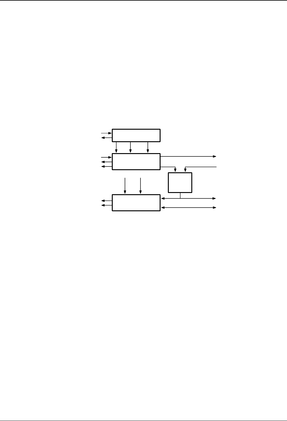
Chapter 3 – Fax Class 2 Commands
Multi-Tech Systems, Inc. SocketModem MT5634SMIxx Reference Guide (S000263C) 72
Parameter Commands
All Class 2 parameters can be read, written, and tested for the range of legal values by the modem.
The general syntax is described in the AT Command section of this Chapter.
T.30 Session Parameters
Group 3 fax devices negotiate session parameters in the DIS, DCS and DTC frames. The following
parameters are provided to condition the fax modem for the capabilities it will offer, and to report the
negotiated session settings.
The three primary T.30 session parameters are +FCC [FDCC], +FIS [FDIS] and +FCS [FDCS],
described in 2.5.1.1–2.5.1.3. These are compound parameters using values listed in Table 3.5. The
Figure below illustrates their relationships:
DTE Write
DTE Read
DTE Write
DTE Report
DTE Read
DTE Write
DTE Read
+FCC
DCE Capabilities
+FIS
DCE Ne gotia t ing
Position
+FCS Negotiated
Session Parameters
On send,
determine
DCS in
fax DCE
Cold
Start Write
+FDCC End of
Session
Cold
Start End of
Session
0,0,0,0,0,0,0,0
Remote DCS on receive
DIS/DTC
from remote
station
DCS if send
DIS/DTC if receive
Virtual DIS
on send
T.30 session parameters
Modem Capabilities Parameters
Class 2.1 +FCC=
Write Syntax: +FCC=VR,BR,WD,LN,DF,EC,BF,ST,JP
Values: See Table 3.5
Default: 1,5,0,2,0,0,0,0
+FCC allows the host to sense and constrain the capabilities of the facsimile modem,
from the choices defined in ITU-T T.30. When +FCC is modified by the host, the
modem will copy +FCC into +FIS.
Note: The Multi-Tech implementation does not include the T.32 subparameter WD 3
and 4 values or the EC 2 and 3 values; also, for subparameter BF only the 00 value
is implemented.
Class 2 +FDCC=
Write Syntax: +FCC=VR,BR,WD,LN,DF,EC,BF,ST
Values: See Table 3.5.
Default: 1,5,0,2,0,0,0,0
The Class 2 parameter is essentially the same as the Class 2.1 parameter except
that it lacks the JP subparameter, and the modem copies +FDCC into +FDIS.

Chapter 3 – Fax Class 2 Commands
Multi-Tech Systems, Inc. SocketModem MT5634SMIxx Reference Guide (S000263C) 73
Current Sessions Parameters
Class 2.1 +FIS=
Write Syntax: +FIS=VR,BR,WD,LN,DF,EC,BF,ST,JP
Values: See Table 3.5
Default: 1,3,2,2,0,0,0,0,0
The +FIS parameter allows the host to sense and constrain the capabilities used for
the current session. The modem uses +FIS to generate DIS or DTC messages
directly, and uses +FIS and received DIS messages to generate DCS messages.
The modem sets the +FIS parameter from the +FCC parameter on initialization,
when +FCC is written, and at the end of a session.
Class 2 +FDIS=
Write Syntax: +FCC=VR,BR,WD,LN,DF,EC,BF,ST
Values: See Table 3.5
Default: 1,3,2,2,0,0,0,0
The Class 2 parameter is essentially the same as the Class 2.1 parameter except
that it lacks the JP subparameter, and the +FDIS parameter is set from the +FDCC
parameter.
Current Session Results
Class 2.1 +FCS?
Read syntax: +FCS?
Response: VR,BR,WD,LN,DF,EC,BF,ST,JP
Values: See Table 3.5
Default: 0,0,0,0,0,0,0,0,0
The +FCS parameter is loaded with the negotiated T.30 parameters for the current
session. A transmitting modem generates DCS; a receiving modem gets DCS from
the remote station. The host may only read this parameter.
The +FCS parameter is set to 0,0,0,0,0,0,0,0 on initialization, on +FIP command
execution, and at the beginning of a session. If the host issues a +FCS? command in
the initial state, the modem will report: <CR><LF>0,0,0,0,0,0,0,0<CR><LF>
The contents of +FCS are spontaneously reported during execution of +FDR (2.3.5)
or +FDT (2.3.3) commands by the +FCS:VR,BR,WD,LN,DF,EC,BF,ST,JP response,
using the same compound parameter format. See T.30 Phase B Negotiation
Responses section.
Class 2 +FDCS?
Read syntax: +FDCS?
Response: +FDCS=VR,BR,WD,LN,DF,EC,BF,ST or: +FDCS=
Values: See Table 3.5
Default: 0,0,0,0,0,0,0,0
The Class 2 parameter is essentially the same as the Class 2.1 parameter except
that the response lacks the JP subparameter.

Chapter 3 – Fax Class 2 Commands
Multi-Tech Systems, Inc. SocketModem MT5634SMIxx Reference Guide (S000263C) 74
T.30 Session Subparameters
Several commands and responses reference T.30 session negotiated parameters. These are described
by a set of common subparameters, which are described in Table 3.5. Optional parameter values are
marked with an asterisk (*).Unspecified parameter values are reserved for future use.
The +FCC [+FDCC], +FIS [+FDIS], and +FCS [+FDCS] compound parameters, described in Parameter
Commands sections, use these session subparameters. On writes, unspecified subparameters are
unchanged.
The +FIS: [+FDIS:], +FCS: [+FDCS:], and +FTC: [+FDTC:] session report responses, described in
T.30 Phase B Negotiation Responses section, also use these subparameters.
For test response, ranges of values are reported for each subparameter, enclosed in parentheses
characters. For example, a modem response to +FCC=? [+FDCC=?] could report:
<CRLF>(0-1),(0-3),(0-4),(0-2),(0),(0),(0),(0-7),(0)<CRLF>
Example: +FIS=0,3,0,2,0,0,0,1,0 is interpreted as follows:
Value Label Description
0 VR 98 dpi vertical resolution
3 BR 9600 bit/s
0 WD 1728 pixels
2 LN unlimited length
0 DF 1-D modified Huffman coding
0 EC no ECM
0 BF no BFT
1 ST 5 ms scan time
0 JP no JPEG

Chapter 3 – Fax Class 2 Commands
Multi-Tech Systems, Inc. SocketModem MT5634SMIxx Reference Guide (S000263C) 75
Table 3.5. T.30 Session Subparameter Codes
Note: Class 2.0/2.1 is shown in hexadecimal values. Class 2 is shown is decimal values.
Label Function Class 2.0/2.1 Class 2 Description
VR Vertical
resolution
(Note 1)
00h
01h
*02h
*04h
*08h
*10h
*20h
*40h
*Class 2.1 only
0
1
R8 × 3.85 l/mm, (98 dpi) Normal
R8 × 7.7 l/mm, (196 dpi) Fine
R8 × 15.4 l/mm
R16 × 15.4 l/mm
200 dpi × 100 l/25.4 mm
200 dpi × 200 l/25.4 mm
400 dpi × 400 l/25.4 mm
300 dpi × 300 l/25.4 mm
Bit rate
(Note 2)
0h
1h
2h
3h
4h
5h
0
1
2
3
+FCC/+FIS description
2 400 bit/s preferred
4 800 bit/s preferred
7 200 bit/s preferred
9 600 bit/s preferred
12 000 bit/s preferred
14 400 bit/s preferred
all with V.8 optional
+FCS description
2 400 bit/s selected
4 800 bit/s selected
7 200 bit/s selected
9 600 bit/s selected
12 000 bit/s selected
14 400 bit/s selected
6h
7h
8h
9h
Ah
Bh
Ch
Dh
Class 2.1 only
16 800 bit/s preferred
19 200 bit/s preferred
21 600 bit/s preferred
24 000 bit/s preferred
26 400 bit/s preferred
28 800 bit/s preferred
31 200 bit/s preferred
33 600 bit/s preferred
all with V.8 implied
16 800 bit/s selected
19 200 bit/s selected
21 600 bit/s selected
24 000 bit/s selected
26 400 bit/s selected
28 800 bit/s selected
31 200 bit/s selected
33 600 bit/s selected
BR
V.34 bit rate
(Class 2.1
only)
Eh Reserved Reserved
WD Page width in
pixels
0h
1h
2h
0
1
2
R8 R16 200 300 400
d/mm d/mm dpi dpi dpi
1728 3456 1728 2592 3456
2048 4096 2048
2432 4864 2432
LN Page length 0h
1h
2h
0
1
2
A4, 297 mm
B4, 364 mm
Unlimited length
DF Data
compression
format
0h
1h
3h
0
1
1-D modified Huffman (T.4)
2-D modified read (T.4)
2-D modified read (T.6)
EC Error
correction,
T.30
0h
1h
0
1
2
Disable ECM
64-byte frames, Annex A/T.30
256-byte frames, Annex A/T.30
BF Binary file
transfer
00h 0 Disable file transfer modes
ST Scan time/line
0h
1h
2h
3h
4h
5h
6h
7h
0
1
2
3
4
5
6
7
VR = 0
0 ms
5 ms
10 ms
10 ms
20 ms
20 ms
40 ms
40 ms
VR > 0
0 ms
5 ms
5 ms
10 ms
10 ms
20 ms
20 ms
40 ms

Chapter 3 – Fax Class 2 Commands
Multi-Tech Systems, Inc. SocketModem MT5634SMIxx Reference Guide (S000263C) 76
Label Function Class 2.0/2.1 Class 2 Description
JP JPEG for
color and
B&W
(Note 2)
00
01
02
04
08
10
20
40
Disable JPEG coding
Enable JPEG coding (T.81)
Full color mode
Enable preferred Huffman tables (Note 3)
12 bits/pel/component
No subsampling (1:1:1)
Custom illuminant
Custom gamut range
Notes:
1 For subparameter VR, values 00, 01, 02, 04, 08, 10, 20 and 40 (hexadecimal) indicate a single choice; they are the only values
allowed in the +FCS parameter and +FCS: report. All values that are sums of these values shall only be used to indicate multiple
capabilities; these are allowed in +FIS and +FCC parameters. For example, value 07 (01 + 02 + 04) would indicate capability for
all metric-based resolutions.
2 For subparameter JP, values 00, 01, 02, 04 08, 10, 20 and 40 (hexadecimal) indicate a single choice. All values that are sums of
these values shall only be used to indicate multiple capabilities in +FIS and +FCC subparameters and to indicate the choice in
the +FCS subparameter. For example, to indicate support for JPEG, full color mode ,and no subsampling, the host should set the
JP subparameter to 01 + 02 + 10 = 13h. If one or several of the values 02h to 40h are not used, that means that the default value
for the subparameter (e.g. respectively: gray-scale, custom Huffman tables, 8 bit/pel/component, 4:1:1 subsampling ratio, D50
illuminant, default gamut range) is used, as defined in Annex E/T.30 and Annex G/T.4.
3 The modem ignores this value in •FCC and in •FIS when generating DIS or DTC frames.

Chapter 3 – Fax Class 2 Commands
Multi-Tech Systems, Inc. SocketModem MT5634SMIxx Reference Guide (S000263C) 77
Local ID String
Class 2.1 +FLI
Write syntax: +FLI=”<local ID string>”
Values: 20-character printable ASCII string
Mandatory values: 20-character string, Table 3/T.30
Default: Null String
The modem generates a TSI or CSI frame if FLI is not a Null String. Table 3/T.30
includes digits 0–9, the + character, and the space character.
The modem transmits ID string characters to the remote station in reversed time
order from the order in the command line. For example, if the command line
AT+FLI="+1 234 567 8901"<CR> is issued, the modem would send a CSI or TSI
rame with FIF (hexadecimal) consisting of
<20><20><20><20><20><31><30><39><38><20><37><36><35><20><34>
<33><32><20><31><2B>
If less than 20 characters are specified in a non-Null String, the modem appends
space characters (<20>). If the specified string is more than 20 characters in
length, an ERROR result code is generated.
Class 2 +FLID
Write syntax: +FLID=”<local ID string>”
Valid values: 20-character printable ASCII string
Mandatory values: 20-character string, Table 3/T.30
Default value: Null String
The Class 2 parameter is essentially the same as the Class 2.1 parameter.
Local Polling ID String
Class 2.1 +FPI
Write syntax: +FPI=”<local polling ID string>”
Values: 20-character printable ASCII string
Mandatory Values: 20-character string, Table 3/T.30
Default: Null String
The modem generates a CIG frame if FPI is not a Null String. CIG is used in
polling sessions. Table 3/T.30 includes digits 0–9, the + character, and the space
character.
Like the +FLID command, the modem transmits ID string characters to the
remote station in reversed order from the order in the command line.
Class 2 +FCIG
Write syntax: +FCIG=”<local ID string>”
Values: 20-character printable ASCII string
Mandatory Values: 20-character string, Table 3/T.30
Default: Null String
The Class 2 parameter is essentially the same as the Class 2.1 parameter.

Chapter 3 – Fax Class 2 Commands
Multi-Tech Systems, Inc. SocketModem MT5634SMIxx Reference Guide (S000263C) 78
Non-standard Frame FIF Octet String
Class 2.1 +FNS
Write syntax: +FNS="< hexadecimal-coded octet string>"
Values: up to 90 octets
Default: Null String
If +FNS is not a Null String, the modem sends the corresponding non-standard
facilities frame. The type of frame is determined by the type of negotiation frame to
be sent: NSF sent with DIS; NSS sent with DCS; NSC sent with DTC.
The modem only delivers the data; the host must determine the content. The first
octet must be the country code (see Recommendation T.35).
Class 2 There is no equivalent parameter in Class 2.
Indicate Document to Poll
Class 2.1 +FLP
Write syntax: +FLP=<value>
Values: 0, 1
Default: 0
+FLP=0 The host has no document to poll.
+FLP=1 The host has a document ready for polling. The modem reports this to the
remote station in the DIS frame. The modem resets this parameter to 0
after a polled document is sent.
Class 2 +FLPL
Write syntax: +FLPL=<value>
Values: 0, 1
Default: 0
The Class 2 parameter is the same as the Class 2.1 parameter except for the name.
Request to Poll
Class 2.1 +FSP
Write syntax: +FSP=<value>
Values: 0, 1
Default: 0
+FSP=0 The host does not want to poll.
+FSP=1 The host can receive a polled document. The modem resets this parameter
to 0 after a polled document is received.
Class 2 +FSPL
Write syntax: +FSPL=<value>
Values: 0, 1
Default: 0
The Class 2 parameter is the same as the Class 2.1 parameter except for the name.

Chapter 3 – Fax Class 2 Commands
Multi-Tech Systems, Inc. SocketModem MT5634SMIxx Reference Guide (S000263C) 79
Capability to Receive
Class 2.1 +FCR
Write syntax: +FCR=<value>
Values: 0, 1
Default: 0
+FCR=0 The modem will not receive message data; also, the modem will not be
able to poll a remote device. This can be used when the host has
insufficient storage, or if the modem does not have a Phase C (V.27ter,
V.29) demodulator. The modem can send and can be polled for a file.
+FCR=1 The modem can receive message data.
+FCR is sampled in ITU T.30 Phase B and Phase D.
Class 2 +FCR
Write syntax: +FCR=<value>
Values: 0, 1
Default: 0
The Class 2 parameter is identical to the Class 2.1 parameter.
Session Message Reporting
Class 2.1 +FBU
Write syntax: +FBU=<value>
Valid values: 0, 1
Default value: 0
+FBU=0 Disables HDLC frame reporting.
+FBU=1 Enables the modem to report the contents of Phase B and Phase D HDLC
frames to the host, as they are sent and received, in addition to other
responses. Reports use the +FHT: and +FHR: responses, described in the
Session Message Report Responses section of this chapter.
Class 2 +FBUG
Write syntax: +FBUG=<value>
Values: 0, 1
Default: 0
The Class 2 parameter is identical to the Class 2.1 parameter except for the name.

Chapter 3 – Fax Class 2 Commands
Multi-Tech Systems, Inc. SocketModem MT5634SMIxx Reference Guide (S000263C) 80
Negotiation Reporting
Class 2.1 +FNR
Write syntax: +FNR=<rpr>,<tpr>,<idr>,<nsr>
Values: 0, 1 for each subparameter
Default: 0,0,0,0
+FNR is a compound parameter, used to control the reporting of messages
generated during T.30 Phase B negotiations. There are four switches, for four types
of reports:
Setting Reference Description
rpr=0
rpr=1
2.4.2.1 Receiver parameters are not reported; +FIS: and +FTC: reports are suppressed.
Receiver parameters are reported; +FIS: and +FTC: reports are generated.
tpr=0
tpr=1
2.4.2.1 Transmitter parameters are not reported; +FCS: reports are suppressed. (Note)
+FCS parameter is still loaded. Transmitter parameters are reported; +FCS:
reports are generated.
idr=0
idr=1
2.4.2.3 ID strings are not reported; +FTI:, +FCI: and +FPI: reports are suppressed.
ID strings are reported; +FTI:, +FCI: and +FPI: reports are generated.
nsr=0
nsr=1
2.4.2.4 Non-standard frames not reported; +FNF:, +FNS: and +FNC: reports suppressed.
Non-standard frames reported; +FNF:, +FNS: and +FNC: reports generated.
Note
If tpr=0, the negotiated image data format will not be reported. Without that report, the host must send
image data that is mandated by Recommendation T.30 (normal resolution, A4 length, 1728 width,
1-D coding) or it must enable the corresponding format conversion (+FFC). Otherwise, the data format
negotiated and the data format sent might not match, causing the facsimile session to fail.
Class 2 There is no equivalent parameter in Class 2.
Address & Polling Capabilities
Class 2.1 +FAP
Write syntax: +FAP=<sub>,<sep>,<pwd>
Values: 0 (disabled) or 1 (enabled) for each subparameter
Default: 0,0,0
The +FAP subparameters allow the host to indicate the inbound subaddressing,
selective polling, and passwords capabilities to the remote station via the
corresponding bits in the DIS or DTC frames: bit 47 for SEP, bit 49 for SUB, bit 50 for
PWD.
These subparameters also control the reporting of those frames, if received. For
example, if the <sep> subparameter value is set to 0 (disabled), then the modem
ignores a received SEP frame; if the <sep> subparameter is set to 1 (enabled), the
modem reports the received frame using the +FPA: report.
Class 2 There is no equivalent parameter in Class 2.

Chapter 3 – Fax Class 2 Commands
Multi-Tech Systems, Inc. SocketModem MT5634SMIxx Reference Guide (S000263C) 81
Addressing & Polling Frames
Class 2.1 +FSA, +FPA, +FPW
Write syntax: +FSA="<destination Subaddress string>"
+FPA="<selective Polling Address string>"
+FPW="<Password string>"
Values: 20 digit numeric ASCII string: digits 0-9, *, # and space only
Default: Null String
The modem sends the numeric string contained in +FSA, +FPA or +FPW at the times
specified in Recommendation T.30, if the corresponding parameter is not a Null
String. The +FPW parameter is used for the PWD frame sent with either DTC or with
DCS.
The +FSA=?, +FPA=?, and +FPW=? test commands report the corresponding
ranges of character values supported.
The modem transmits digit string characters to the remote station in reversed time
order from the order in the command line. If less than 20 characters are specified in a
non-Null String, the modem appends space characters. If the specified string is more
than 20 characters in length, an ERROR result code is generated.
Class 2 There are no equivalent parameters in Class 2.

Chapter 3 – Fax Class 2 Commands
Multi-Tech Systems, Inc. SocketModem MT5634SMIxx Reference Guide (S000263C) 82
T.30 Procedure Control Parameters
The fax modem makes decisions at several nodes in the T.30 procedure. These
parameters allow a host to sense or determine fax modem policy for these procedure decisions.
Page Transfer Status
Class 2.1 +FPS
Write syntax: + FPS=<ppr>
Values: 1, 2, 3
Default: 1
The +FPS parameter contains a value representing the post page response, including
copy quality and related end-of-page status. These values correspond to post page
response messages defined in T.30. The receiving modem sets this parameter after
it receives a page of Phase C data. The transmitting modem sets this parameter with
the status reported by the receiving station. The host may inspect or modify this
parameter.
The set of <ppr> values is defined in Table 3.6. These values are also reported by
the +FPS:<ppr> response to the +FDR command. The Multi-Tech implementation
does not support <ppr> values 4 and 5.
Table 3.6 Class 2.1 T.30 Post Page Response Message Codes
Value Mnemonic Description
1 MCF Page good.
2 RTN Page bad; retrain requested.
3 RTP Page good; retrain requested.
4* PIN Page bad; retrain requested; interrupt request accepted.
5* PIP Page good; interrupt request accepted.
The modem may set this parameter to values 1, 2 or 3 based on its own copy quality
checking or access to received signal quality. The modem sets this parameter to a
value of 1 if copy quality checking is disabled (+FCQ=0).
A receiving host may do its own copy quality checking or decide to request a
procedure interrupt from the remote station. The host will receive a report of the copy
quality <ppr> as part of the +FPS:<ppr>,<lc>,<blc>,<cblc> response. The host may
modify this result before it issues the next action command (e.g., +FDR), which
releases the corresponding post page response to the remote facsimile station.
Class 2 +FPTS
Write syntax: + FPTS=<ppr>
Valid values: 1, 2, 3, 4, 5
Default value: 1
Except for the name and the range of values, the Class 2 parameter is identical to the
Class 2.1 parameter.

Chapter 3 – Fax Class 2 Commands
Multi-Tech Systems, Inc. SocketModem MT5634SMIxx Reference Guide (S000263C) 83
Copy Quality Checking
Class 2.1 +FCQ
Write syntax: +FCQ=<rq>,<tq>
Values: 0, 1 for <rq>
0 for <tq>
Default: 1 for <rq>
0 for <tq>
Other values for <rq> and <tq> are not supported in the Multi-Tech implementation.
The +FCQ parameter controls copy quality checking and correction by a facsimile
modem. The <rq> subparameter controls copy quality checking and correction of
data received from the remote station and delivered to the local host; the <tq>
subparameter controls copy quality checking and correction of image data received
from the local host and sent to the remote station.
The modem reports on Received Copy Quality to the host in the page status report,
+FPS:<ppr>,<lc>,<blc>,<cblc>,<lbc>, and records it in the +FPS parameter.
+FCQ=0,0 modem receive copy quality checking is disabled; the modem will
generate copy quality OK (MCF) responses to complete pages, and set
+FPS=1. modem transmit copy quality checking is disabled; the host is
responsible for T.4 or T.6 compliance.
+FCQ=1,0 modem receive copy quality checking is enabled; the modem will
determine the recommended Post Page Message, and store it into the
+FPS parameter. modem transmit copy quality checking is disabled; the
host is responsible for T.4 or T.6 compliance.
Class 2 +FCQ
Write syntax: +FCQ=<value> Valid values: 0, 1
Default value: 0
This parameter controls copy quality checking by the receiving facsimile modem.
The modem will generate a page transfer report, indicated with the
+FPTS=<ppr>,<lc>,<blc>,<cblc> response and posted in the +FPTS parameter. The
+FCQ parameter setting also conditions the generation of bad line count <blc> and
consecutive bad line count <cblc> subparameters.
+FCQ=0 The modem does no copy quality checking. The modem will generate
copy quality OK (MCF) responses to complete pages, and set +FPS=1.
+FCQ=1 The modem can check 1-D Phase C data. The host must check copy
quality for 2-D Phase C data. On new -V92 modems, +FCQ=1 means it
will also check 2-D Phase C data.

Chapter 3 – Fax Class 2 Commands
Multi-Tech Systems, Inc. SocketModem MT5634SMIxx Reference Guide (S000263C) 84
Receive Quality Thresholds
Class 2.1 +FRQ
Write syntax: +FRQ=<pgl>,<cbl>
Values: 0 to 64h for <pgl>
0 to FFh for <cbl>
Default: 0,0
This compound parameter replaces the +BADMUL and +FBADLIN parameters used
in Class 2. The modem may use it to make the "Copy Quality OK" decision in the
T.30 flow chart (Figure A.7/T.30). If it is used, the modem shall judge copy quality
unacceptable if either the percentage of good lines is too low or too many
consecutive lines contain errors. Bad line counts are reported in the +FPS:<blc>
response. A value of 0 disables either subparameter for use in copy quality checking.
The first subparameter, <pgl>, specifies the percentage of good lines (e.g. with
negotiated number of pixels) required for a page to be considered acceptable. For
example, if the modem counted bad lines (as reported in the +FPS <blc>
subparameter) and total line count (as reported in the +FPS<lc> subparameter); the
percentage of good lines would be computed by the following equation:
100 × (<lc> – <blc>) / <lc>
If the resulting value is less than the value in <pgl>, the page is unacceptable.
The second subparameter, <cbl>, specifies the maximum tolerable number of
consecutive bad lines. If this value is exceeded for a given page, the modem shall
consider the page unacceptable.
If the page is found unacceptable by either criteria, the modem shall report the value
2 for the +FPS <ppr> subparameter, and store that value into the +FPS parameter.
Class 2 +FBADMUL
Write syntax: +FBADMUL=<value>
Values: 0–255
Default: 20
This is one of two Class 2 parameters used to determine “Copy Quality OK” on the
T.30 flow chart. The number of lines received with a bad pixel count is multiplied by
this number. If the result exceeds the number of lines in the page, then the error rate
is too high. A value of 20 corresponds to a 5% error rate.
A value of 0 implies that error checking is not present or is disabled.
Class 2 +FBADLIN
Write syntax: +FBADLIN=<value>
Valid values: 0–255
Default value: 10
This is the other Class 2 parameter used to determine “Copy Quality OK.” If the
number of consecutive lines in normal resolution (98 dpi) mode that have pixel count
errors is equal to or greater than <value>, then the copy quality is unacceptable. If
the number of consecutive lines in fine resolution (196 dpi) mode that have pixel
count errors is equal to or greater than <value> × 2, then the copy quality is
unacceptable. “Copy Quality Not OK” occurs if either the error percentage is too high
or if too many consecutive lines contain errors. Bad line counts are reported in the
+FPTS: response.
A value of 0 implies that error checking is not present or disabled.

Chapter 3 – Fax Class 2 Commands
Multi-Tech Systems, Inc. SocketModem MT5634SMIxx Reference Guide (S000263C) 85
Adaptive Answer
Class 2.1 +FAA
Write syntax: +FAA=<value>
Valid values: 0, 1
Default value: 0
+FAA=0 The modem shall answer only as a Class 2.1 facsimile device. No
automatic switching of service class shall occur based on the calling
device type.
+FAA=1 The modem can answer and automatically determine whether to answer
as a facsimile modem or as a data modem. If the modem automatically
switches, it resets the +FCLASS parameter to 0. +FCLASS does not
affect switching to Class 2.1 from other classes or switching to classes
other than Class 0.
Note: If the modem reconfigures itself to data modem operation in
adaptive answering, the host must reissue a new +FCLASS=2.1
command to enable subsequent Service Class 2.1 facsimile operation.
Class 2 +FAA
Write syntax: +FAA=<value>
Valid values: 0, 1
Default value: 0
+FAA=0 Constrains the modem to answer as set by +FCLASS.
+FAA=1 The modem can answer and automatically determine whether to answer
as a facsimile modem or as a data modem. If the modem automatically
switches, it modifies FCLASS as appropriate.
Host Phase C Response Timeout, +FCT
Write syntax: +FCT=<value>
Valid values: 0–255 in 100-millisecond units.
Default value: 30
This determines how long the modem waits for a command after reaching the end of
data when transmitting in Phase C. When this time-out is reached a cancellation
signal and then a +FHS:43 is issued to the host and the remote side is sent a
disconnect frame.
+FPHCTO, Host Phase C Response Time-out
Class 2.1/2.0 Not Applicable.
Class 2
Syntax: +FPHCTO=<value>
Value Values: 0 – 255
Default Value: 30
+FPHCTO=? 0-255 +FPHCTO? 30 Default value. Range: 0 - 255
This command specifies the waiting period during a fax transmission beyond which
the transmission is automatically terminated with an end-of-page command.

Chapter 3 – Fax Class 2 Commands
Multi-Tech Systems, Inc. SocketModem MT5634SMIxx Reference Guide (S000263C) 86
T.30 Session Error Report, +FAXERR
Class 2.0/2.1 not supported
Class 2 +FAXERR
Read syntax: > +FAXERR= <table value>, read only
Valid values: 0–255; see Table 3.5 for meaning
This read only parameter indicates the cause of a hang-up. Table 3.5 shows the valid
values for this parameter as well as the meaning of each value. +FAXERR is set by
the modem at the conclusion of a fax session. The modem will reset this to 0 at the
beginning of Phase A off-hook time.
Minimum Phase C Speed, +FMS
Class 2.0/2.1 +FMS
Write syntax: +FMS=BR
Valid values: 0–5, in BR subparameter codes
Default value: 0 (V.27ter @ 2400 bit/s)
This optional parameter limits the lowest negotiable speed for a session. It is useful
for limiting the cost of a transmission by requiring a minimum transmission speed. If a
facsimile cannot negotiate to a minimum speed, it performs an orderly disconnect.
The units are the same as those defined for the BR Bit Rate subparameter as defined
in Table 3.6 in this manual.
Class 2 +FMINSP
Write syntax: +FMINSP=BR
Valid values: 0–5, in BR subparameter codes
Default value: 0 (V.27ter @ 2400 bit/s)
This optional parameter limits the lowest negotiable speed for a session. It is useful
for limiting the cost of a transmission by requiring a minimum transmission speed. If a
facsimile cannot negotiate to a minimum speed, it performs an orderly disconnect.
The units are the same as those defined for the BR Bit Rate subparameter, as
defined in Table 3.6 in this manual.

Chapter 3 – Fax Class 2 Commands
Multi-Tech Systems, Inc. SocketModem MT5634SMIxx Reference Guide (S000263C) 87
Phase C Data Format Parameters
Data Bit Order: +FBO and +FBOR
Class 2.0/2.1 +FBO
Write syntax: +FBO=<value>
Valid values: 0, 1
Default value: 0
This parameter controls the mapping between PSTN facsimile data and the host-
modem link. There are two choices:
+FBO=0 Direct bit order for both Phase C data. The first bit transferred of each
byte on the host-modem link is the first bit transferred on the PSTN data
carrier.
+FBO=1 Reversed bit order for Phase C data. The last bit transferred of each byte
is the first bit transferred on the PSTN data carrier.
The effect of this parameter is illustrated for the EOL pattern in the Phase C Data
Format Parameters section in this chapter.
Class 2 +FBOR
Write syntax: +FBOR =<value>
Valid values: 0, 1
Default value: 0
This parameter controls the mapping between PSTN facsimile data and the host-
modem link. There are two choices:
+FBOR=0 Direct bit order for both Phase C data. The first bit transferred of each
byte on the host-modem link is the first bit transferred on the PSTN
data carrier. Applies to FAX sending for all Multi-Tech modems.
+FBOR=1 Reversed bit order for Phase C data. The last bit transferred of each
byte is the first bit transferred on the PSTN data carrier. Applies to
FAX sending for all Multi-Tech modems.
The effect of this parameter is illustrated for the EOL pattern in the Phase C Data
Format Parameters section in this chapter.
Phase C Received EOL Alignment: +FEA and +FREL
Class 2.0/2.1 +FEA
Write syntax: +FEA=<value>
Valid values: 0, 1
Default value: 0
+FEA=0 EOL patterns are bit-aligned as received.
+FEA=1 The last received bits of EOL patterns are byte-aligned by the
modem, with necessary zero fill bits inserted. There are two 2-byte
binary EOL patterns, in which xxxx represents previous data bits, zero
bits, or other leading data:
+FBO=0: 0000xxxx 10000000
+FBO=1: xxxx0000 00000001
Class 2 +FREL
Write syntax: +FREL=<value>
Valid values: 0, 1
Default value: 0
+FREL=0 EOL patterns are bit-aligned as received.
+FREL=1 The last received bits of EOL patterns are byte-aligned by the
modem, with necessary zero fill bits inserted. There are two 2-byte
binary EOL patterns, in which xxxx represents previous data bits, zero
bits, or other leading data:
+FBOR=1: 0000xxxx 10000000
+FBOR=1: xxxx0000 00000001

Chapter 3 – Fax Class 2 Commands
Multi-Tech Systems, Inc. SocketModem MT5634SMIxx Reference Guide (S000263C) 88
Format conversion, +FFC
Class 2.0/2.1
Write syntax: +FFC=<vrc>,<dfc>,<lnc>,<wdc>
Valid values: see table below
Default values: manufacturer’s option
Mandatory values: 0,0,0,0
This compound parameter determines the modem response to mismatches between
the Phase C data delivered after the +FDT command and the data format parameters
negotiated for the facsimile session. For mismatch checking, the modem depends on
the host to indicate the data format with embedded <DLE><format> character pairs.
If these format indicators are not provided, the modem shall assume that the format
is as negotiated for that session.
For each subparameter, value 0 determines that mismatch checking is disabled, and
all format codes of this type are ignored. Value 1 determines that mismatch checking
is enabled, with session termination if the format codes do not match the negotiated
format reported in +FCS: responses. Other values enable degrees of format
conversion. Unspecified values are reserved.
Class 2 Not Applicable
Note that the four arguments of the Class 2.0/2.1 command +FFC cover the same
technical content as these four separate Class 2 commands (which are described in
detail below):
+FVRFC (for vertical resolution),
+FDFFC (for data compression format version),
+FLNFC (for page length format conversion), and
+FWDFC (for page width format conversion).
Setting Description
vrc=0
vrc=1
vrc=2
vrc=3
Vertical resolution format codes ignored
Vertical resolution checking enabled
Vertical resolution conversion enabled for 1-D data
Vertical resolution conversion enabled for 2-D data
dfc=0
dfc=1
dfc=2
Data format codes ignored
Data format checking enabled
Data format conversion enabled
lnc=0
lnc=1
lnc=2
lnc=3
Page length format codes ignored
Page length checking enabled
Page length conversion enabled for 1-D data
Page length conversion enabled for 2-D data
wdc=0
wdc=1
wdc=2
Page width format codes ignored
Page width checking enabled
Page width conversion enabled

Chapter 3 – Fax Class 2 Commands
Multi-Tech Systems, Inc. SocketModem MT5634SMIxx Reference Guide (S000263C) 89
Vertical Resolution Format Conversion +FVRFC
Class 2.0/2.1 Not Applicable
Class 2
Write syntax: +FVRFC=<value>
Valid values: 0, 1, 2
Default value: 0
This parameter determines the modem response to a mismatch between the vertical
resolution negotiated for the facsimile session, reported by the +FCS:VR
subparameter, and the Phase C data desired by the host, indicated by the optional
+FDT:VR subparameter, or the +FIS=VR subparameter for +FDR operation.
FVRFC=0 Disables mismatch checking. The host must check the +FCS:VR
subparameter, and transfer matching data.
FVRFC=1 Enables mismatch checking. An implied +FKS command is executed
on mismatch detection.
FVRFC=2 Enables mismatch checking, with resolution conversion of 1-D data in
the modem. An implied +FKS command is executed on 2-D mismatch
detection.
Data Compression Format Conversion, +FDFFC
Class 2.0/2.1 Not Applicable
Class 2
Write syntax: +FDFFC=<value>
Valid values: 0
Default value: 0
This parameter determines the modem response to a mismatch between the data
format negotiated for the facsimile session, reported by the +FCS:DF subparameter,
and the Phase C data desired by the host, indicated by the optional +FDT:DF
subparameter, or the +FIS=DF subparameter for +FDR operation.
FDFFC=0 Disables mismatch checking. The host must check the +FCS:DF
subparameter, and transfer matching data.
Page Length Format Conversion, +FLNFC
Class 2.0/2.1 Not Applicable
Class 2 Write syntax: +FLNFC=<value>
Valid values: 0, 1, 2
Default value: 0
This parameter determines the modem response to a mismatch between the page
length negotiated for the facsimile session, reported by the +FCS:LN subparameter,
and the Phase C data desired by the host, indicated by the optional +FDT:LN
subparameter, or the +FIS=LN subparameter for +FDR operation. A mismatch would
require clipping or scaling a longer format to a shorter one.
FLNFC=0 Disables mismatch checking. The host must check the +FCS:LN
subparameter and transfer matching data.
FLNFC=1 Enables mismatch checking. An implied +FKS command is executed
on mismatch detection.
FLNFC=2 Enables mismatch checking, with page length conversion of 1-D data
in the modem. An implied +FKS command is executed on 2-D
mismatch detection.

Chapter 3 – Fax Class 2 Commands
Multi-Tech Systems, Inc. SocketModem MT5634SMIxx Reference Guide (S000263C) 90
Page Width Format Conversion, +FWDFC
Class 2.0/2.1 Not Applicable
Class 2
Write syntax: +FWDFC=<value>
Valid values: 0, 1, 2
Default value: 0
This parameter determines the modem’s response to a mismatch between the page
width negotiated for the facsimile session, reported by the +FCS:WD subparameter,
and the Phase C data desired by the host, indicated by the optional +FDT:WD
subparameter, or the +FIS=WD subparameter for +FDR operation. A mismatch
would require clipping or scaling a wider format to a narrower one.
FWDFC=0 Disables mismatch checking. The host must check the +FCS:WD
subparameter and transfer matching data.
FWDFC=1 Enables mismatch checking. An implied +FKS command is executed
on mismatch detection.
FWDFC=2 Enables mismatch checking with page width conversion in the
modem.
Fax Flow Control, +FLO
Syntax: +FLO=<value>
Valid values: 0, 1, 2
Default value: 1
The +FLO command allows the host to select and identify the types of flow control
provided and used. A TR29-standard modem can support XON/XOFF flow control.
XON is the ASCII <DC1> character (11h); XOFF is the ASCII <DC3> character (13h).
The modem may provide ITU-T V.24 circuits 106 (CTS) and 133 (RTS) for flow
control.
+FLO=0 No fax flow control.
+FLO=1 Software fax flow control (XON/XOFF flow control in either direction).
+FLO=2 Hardware fax flow control. ITU-T circuit 133 (RTS) is used for flow
control of the modem by the host. Circuit 106 (CTS) is used for flow
control of the host by the modem.
If circuits 106 and 133 are not being used for flow control (+FLO=2),
then circuit 106 drops when an XOFF is sent, and goes high when an
XON is sent. The conductor used for circuit 133 normally reverts to
use as circuit 105 (RTS) when not being used for flow control.

Chapter 3 – Fax Class 2 Commands
Multi-Tech Systems, Inc. SocketModem MT5634SMIxx Reference Guide (S000263C) 91
Set Current Time and Date, AT+FTD
The AT+FTD command is used to set the current date and time. The current time
and date will be tracked automatically by the modem once the time and date are set.
However, these boards do not have a real time clock. So, the accuracy of the time
and date is not guaranteed. It is recommended that the current time and date be set
before each FAX transmit session.
The syntax of the command is:
AT+FTD=<year>, <month>, <hour>, <minute>, <second>, <zone>, <dtsdelta>
The arguments to this command are:
<year> The current year (UTC zone). Range: 1970 to 65535
<month> The current month number (UTC zone). Range: 1 to 12.
January is 1.
<day> The current day of the month. Range: 1 to 31.
<hour> The current hour in military time (UTC zone). Range: 0
to 23.
<minute> The current minute (UTC zone). Range 0 to 59.
<second> The current second (UTC zone). Range 0 to 59.
<zone> The number of seconds east (positive) or west
(negative) that the local time zone is from Greenwich.
Range: -43200 to 43200.
<dtsdelta> Zero if daylight savings time is not in effect at the current
time. Otherwise, the number of minutes to add to the
time. Range 0 to 255.
The current local time is calculated from the UTX (Universal Coordinated Time, i.e.,
GMT) time specified in this command, plus the <zone> offset, plus the <dtsdelta>
offset, plus the number of seconds accumulated by the board since the command
was executed.
Page Header Generation, AT+FPH
The AT+FPH command is used to enable automatic generation of a FAX page
header.
There are four legal formats for the syntax of this command:
AT+FPH=mode, “left”(string is left justified)
AT+FPH=mode, “left’middle’ right”
AT+FPH=mode, “left ’right”
The arguments to this command are:
mode
The mode argument controls generation of the page header. A mode
of 0 disables page header generation. A mode of 1 enables page
header generation and the page header is prepended to the FAX
page data. A mode of 2 enables page header generation and the
page header is overlaid on the first few lines of the FAX page data.
string
The string defines the page header itself. Only ASCII printable
characters are allowed in the string (0x20 through 0x7e). Escape
sequences that are introduced with the percent (%) character are
allowed. The string can be partitioned into one, two, or three parts by
using single-quote characters ( ‘) in the command expression.

Chapter 3 – Fax Class 2 Commands
Multi-Tech Systems, Inc. SocketModem MT5634SMIxx Reference Guide (S000263C) 92
An escape sequence is a “%” followed by an optional width, which may include a
leading left-justification signifier, and then by the escape character itself. It is of the
form %[numbers][-]character. The dash (“-“) denotes left justification. When the
dash is absent, right justification is used. If the width specification starts with a zero,
then, when the escape sequence is expanded, the value will be left-padded with
zeroes. Otherwise, it will be left-padded with spaces.
The following escapes are recognized:
%d (or %D ) The day of the month as a decimal number (range 01 to 31).
%h (or %H ) The hour as a decimal number using a 24-hour clock (range 00 to 23).
%i (or %I ) The hour as a decimal number using a 12-hour clock (range 01 to 12).
%j (or %J) The day of the year as a decimal number (range 001 to 366).
%m The month as a decimal number (range 01 to 12).
%M The minute as a decimal number (two digits).
%p Either ‘am’ or ‘pm’ according to the given time value, or the
corresponding strings.
%P The current page number of the FAX being sent, as computed by the
padding.
%r (or %R) The ID of the remote FAX machine. Leading and trailing blanks are
stripped. A print-style field width specifier such as %20r or %-20r can
be used to print this always in a fixed width field.
%s (or %S) The second as a decimal number (two digits).
%t (or %T) The ID of the transmitting FAX machine. Leading and trailing blanks
are stripped. A print-style field width specifier such as %20t or%-20t
can be used to print this always in a fixed width field.
%y The year as a decimal number without a century.
%Y The year as a decimal number including the century.
%% A literal ‘%’ character.
If the string contains single quotes, it will be partitioned into left, and also possibly,
middle and right parts.
left This portion of the header will be left justified.
middle This portion of the header will be centered.
right This portion of the header will be right justified.
Percent-introduced escapes are processed as above.
Miscellaneous Parameters
Buffer Size, +FBS (Class 2.1 only)
Read syntax: +FBS?
modem response syntax: <bs>,<xoft>,<xont>,<bc>, where
<bs> = total buffer size, )
<xoft> = XOFF threshold,
<xont> = XON threshold,
<bc> = current buffer byte count
This parameter allows the host to determine the characteristics of the modem’s data
buffer. Flow control is mandatory; buffers are needed for flow control. Use of the
reported values would allow a host to transfer data without provoking XOFF.

Chapter 3 – Fax Class 2 Commands
Multi-Tech Systems, Inc. SocketModem MT5634SMIxx Reference Guide (S000263C) 93
Session Message Report Responses
The modem may be commanded to report the T.30 Phase B and Phase D HDLC control frames as
they are sent and received. This service supports session diagnostics and the debugging of host
software. It is enabled by the +FBU parameter described in the Parameter Commands section of this
chapter.
These messages are not generated in direct execution of host action commands; they are generated
for each frame whenever the reported frame is sent or received. The host should not attempt to
change serial port speed or parity with +FBU set. It is desirable to suppress echo of host commands,
if the modem provides that facility.
The data will be reported with each T.30 command separated by <CR><LF>. The fill bits will be
removed. The frame octets will be represented in hex notation, and separated by spaces. Flags and
zero bits are removed. Frame octets are reported in the order sent or received. FCS bytes are
deleted. Frame octets are presented with the LSB as the first bit sent or received.
The following is an example of a received DIS string report:
+FHR: FF 13 80 00 4E 78 FE AD<CR><LF>
Unless specified otherwise, the modem reports these frames before the corresponding responses are
generated. For example, the above examples would occur before the standard +FIS: report was
made.
Report Transmit HDLC Frames, +FHT:
Syntax: +FHT:<transmitted HDLC frame octets>
Reports the HDLC data that was sent by the modem.
Report Received HDLC Frames, +FHR:
Syntax: +FHR:<received HDLC frame octets>
Reports the HDLC data that was received by the modem.

Chapter 3 – Fax Class 2 Commands
Multi-Tech Systems, Inc. SocketModem MT5634SMIxx Reference Guide (S000263C) 94
Sample Modem Control Sessions
Send two pages, 1-D data, no errors (Class 2)
Host
Commands
Modem
Responses
Local Modem
Action
Remote Station Action
AT+FCLASS=2 OK Set Class 2
AT+FLID=”<local ID>” OK Set local ID
ATD<dial string>
+FCON
[+FCSI:”<csi.”]
+FDIS:<dis
codes.
OK
off hook, dial,
send CNG
detect flags
[get CSI]
get DIS
answer,
send ([CED],
V.21 flags,
[CSI],
DIS
AT+FDT
+FDCS:<dcs
codes>
CONNECT
<XON>
[send TSI]
send DCS
send TCF
get CFR
send carrier
[get TSI]
get DCS
get TCF
send CFR
receive carrier
<1st page data> send page data receive page data
<DLE><ETX> OK
AT+FET=0
+FPTS:1
OK
send RTC
send MPS
get MCF
get RTC
get MPS
send MCF
AT+FDT CONNECT
<XON> send carrier receive carrier
<2nd page data> send page data receive page data
AT+FET=2
+FPTS:1
+FHNG:0
OK
send RTC
send EOP
get MCF
send DCN
hang-up
get RTC
get EOP
send MCF
get DCN
hang-up

Chapter 3 – Fax Class 2 Commands
Multi-Tech Systems, Inc. SocketModem MT5634SMIxx Reference Guide (S000263C) 95
Receive two pages, 1-D data, no errors (Class 2)
Host
Commands
Modem Responses Local Modem Action Remote Station Action
AT+FCR=1 OK Enable Reception
AT+FLID=”<local
ID>” OK Set local ID
RING <- Detect ring <- Dials[, send CNG]
ATA
+FCON
[+FCSI”<tsi>”]
+FDIS:<dis codes.
OK
off hook,
send CED,
send CSI,
send DIS,
detect flags,
[get TSI]
get DIS
begin TCF recv
get CED,
get CSI,
get DIS,
send V.21 flags,
[send TSI],
send DIS,
start TCF
AT+FDR
+FCFR
+FDCS:<dcs codes>
CONNECT
accept TCF
send CFR
get page carrier
finish FCT
get CFR
send page carrier
<DC2>
<page data stream>
<DLE><ETX><-
+FPTS:1,<lc>
+FET:0 <-
OK
get page data
detect RTC <-
get MPS
send page data
send RTC
drop carrier,
send MPS
AT+FDR
+FHNG:0 <-
OK
send MCF
get DCN <- get MCF
send DCN

Chapter 3 – Fax Class 2 Commands
Multi-Tech Systems, Inc. SocketModem MT5634SMIxx Reference Guide (S000263C) 96
Send two pages, 1-D data, no errors (Class 2.0)
Square bracketed [ ] responses are conditional on the remote station actions; curly bracketed { }
responses are conditional on switches set by the host. For this example, all reports are enabled:
+FNR=1,1,1,1.
Square bracketed [ ] commas are optional for the host.
Host Commands Modem
Responses
Local Modem
Action
Remote
Station
Action
Notes
AT+FCLASS=2.0 OK Set Class 2
[AT+FPW="<sending
password string>"]
OK Set local PWD host may load a
Password
[AT+FSA="<SUB
string>"]
OK Set SUB Host may load a
destination SUBaddress
[AT+FLI="<local ID>"] OK Set local ID host may load a
local ID
ATD<dial string>
+FCO
[+FNF:<nsf>]
[+FCI:"<csi>"]
{+FIS:<dis
codes>}
OK
off hook, dial,
send CNG
detect flags
[get NSF]
[get CSI]
get DIS
answer,
send [CED],
preamble,
[NSF,]
[CSI,]
DIS
[AT+FNS="<hex NSS
FIF string>"]
OK host may respond to
NSF frame
AT+FDT
<1st page data>
<RTC pattern>
<DLE><mps>
{+FCS:<codes>
}
CONNECT
OK
[send NSS,]
[send PWD,]
[send SUB,]
[send TSI,]
send DCS
send TCF
get CFR
send carrier
send page data
send RTC
send MPS
get MCF
[get NSS,]
[get PWD,]
[get SUB,]
[get TSI,]
get DCS
get TCF
send CFR
get carrier
get data
get RTC
get MPS
send MCF
if +FNS loaded
if +FPW loaded
if +FSA loaded
if +FLI loaded
AT+FDT
<2nd page data>
<RTC pattern>
<DLE><eop>
CONNECT
+FHS:00
OK
send carrier
send 2nd page
send RTC
send EOP
get MCF
send DCN
hang-up
receive
carrier
get 2nd page
get RTC
get EOP
send MCF
get DCN
hang-up

Chapter 3 – Fax Class 2 Commands
Multi-Tech Systems, Inc. SocketModem MT5634SMIxx Reference Guide (S000263C) 97
Receive two pages, 1-D data, no errors (Class 2.0)
In this example, the remote station sends NSS, SUB, PWD and TSI. The local modem has
+FNR=1,1,1,1 and +FAP=1,1,1.
Host
Commands
Modem
Responses
Local Modem
Action
Remote Station
Action
Notes
AT+FCR=1 OK Enable Reception
[AT+FLI="<local
ID>"]
OK Set local ID host may load the
local ID
[AT+FNS="<hex
NSF FIF string>"]
OK host may set up
NSF string
RING <- Detect ring <- Dials[,send CNG]
ATA
+FCO
+FNS:<nss
string>
+FPW:<pwd
string>
+FSA:<sub
string>
+FTI:"<tsi ID>"
{+FCS:<dcs
codes>}
OK
off hook,
send CED,
[send NSF,]
[send CSI,]
send DIS,
detect flags,
get NSS,
get PWD,
get SUB,
get TSI,
get DCS
begin TCF recv
get CED,
[get NSF,]
[get CSI,]
get DIS,
send Preamble,
send NSS,
send PWD,
send SUB,
send TSI,
send DCS,
start TCF
if +FNS loaded
if +FLI loaded
AT+FDR
[+FCS:<dcs
codes>]
CONNECT
<page data>
<RTC pattern>
<DLE><ETX>
+FPS:1,<lc>,0,0,0
+FET:0 <-
OK
accept TCF
send CFR
get page carrier
get page data
detect RTC <-
get MPS <-
finish TCF
get CFR
send carrier
send page data
send RTC,
send MPS
Another +FCS would
be reported if the
parameters changed
after retraining
AT+FDR
<DC2>
CONNECT
<page data>
<RTC pattern>
<DLE><ETX>
<-
+FPS:1,<lc>,0,0,0
+FET:2
OK
send MCF
get carrier
get page data
detect RTC <-
get EOP <-
get MCF
send carrier
send page data
send RTC,
send EOP
AT+FDR
+FHS:00 <-
OK
send MCF
get DCN <-
hang-up
get MCF,
send DCN
hang-up

Chapter 3 – Fax Class 2 Commands
Multi-Tech Systems, Inc. SocketModem MT5634SMIxx Reference Guide (S000263C) 98
Originate and send a two page facsimile with V.34 half-duplex (Class 2.1)
Optional T.30 frames are omitted. +FNR=1,1,, +FIS and +FCS subparameters other than BR and EC
are not shown.
Host
Commands
Modem
Responses Local Modem
Action
Remote Station
Action
Notes
AT+FCLASS=2.1 OK Set class 2
AT+FIS=,B,,,,3,,, OK Set for Rec. V.34,
Annex A/T.30,
Annex C/T.30 or
Annex F/T.30
ATD<dial string>
+FCO
+FIS:,B,,,,1,,,
OK
off-hook, dial,
send CNG
detect ANSam
send CM
get JM
send CJ
negotiate Rec. V.34
begin control chan
get DIS
detect ringing
answer
detect CNG
send ANSam
get CM
send JM
get CJ
negotiate Rec. V.34
begin control chan
send DIS
(“Chan” = channel)
Rec. T.30 selected
with
JM signal from
remote terminal
the remote indicated
28 800 bit/s ability
AT+FDT
<1st page data>
<DLE><mps>
+FCS:,9,,,,1,,,
CONNECT
OK
send DCS
get CFR
switch to primary
chan
send page FCD
switch to control
chan
send MPS
get MCF
get DCS
send CFR
switch to primary
chan
get page data
switch to control
chan
get MPS
send MCF
in this example,
24 400 bit/s is
selected
AT+FDT
<2nd page data>
<DLE><eop>
CONNECT
+FHS:00
OK
switch to primary
chan
send page 2 FCD
switch to control
chan
send EOP
get MCF
send DCN
hang-up
switch to primary
chan
get page 2 FCD
switch to control
chan
get EOP
send MCF
get DCN
hang-up

Chapter 3 – Fax Class 2 Commands
Multi-Tech Systems, Inc. SocketModem MT5634SMIxx Reference Guide (S000263C) 99
Answer and receive a two-page facsimile with V.34 half-duplex (Class 2.1)
Host
Commands
Modem
Responses
Local Modem
Action
Remote Station
Action
Notes
AT+FCLASS=2.1 OK Set class 2
AT+FIS=,D,,,,3,
,,,
OK Set for Rec. V.34,
Annex A/T.30,
Annex C/T.30 or
Annex F/T.30
select max rate
of 33 600 bit/s
RING detect ringing off-hook, dial
ATA
+FCO
OK
answer
detect CNG
send ANSam
get CM
send JM
get CJ
negotiate Rec. V.34
begin control channel
send DIS
send CNG
detect ANSam
send CM
get JM
send CJ
negotiate Rec. V.34
begin control channel
get DIS
Rec. T.30 selected
with JM signal from
remote terminal
the remote indicated
28 800 bit/s ability
AT+FDT +FCS:,B,,,,1,,,,
CONNECT
<1st page data>
<DLE><ETX>
+FPS:1,<lc>,0,0
,0
+FET:0
OK
get DCS
send CFR
switch to primary
channel
get page 1 FCD
switch to control
channel
get MPS
send DCS
get CFR
switch to primary
channel
send page 1 FCD
switch to control
channel
send MPS
in this example,
28 800 bit/s is
selected
AT+FDR CONNECT
<2nd page data>
<DLE><ETX>
+FPS:1,<lc>,0,0
,0
+FET:2
send MCF
switch to primary
channel
get page 2 FCD
switch to control
channel
get EOP
get MCF
switch to primary
channel
send page 2 FCD
switch to control
channel
send EOP
AT+FDR
+FHS:00
OK
send MCF
get DCN
hang-up
get MCF
send DCN
hang-up

Chapter 3 – Fax Class 2 Commands
Multi-Tech Systems, Inc. SocketModem MT5634SMIxx Reference Guide (S000263C) 100
Alphabetic List of Commands and
Responses
Name Description
A Answer command
D<string> Originate command
+FAA= Auto Answer Mode parameter
+FAXERR= Fax Error Value parameter
+FBADLIN= Number of Consecutive Bad Lines for a Bad Page parameter
+FBADMUL= Error Threshold Multiplier
+FBO= Phase C Data Bit Order parameter
+FBS? Buffer Size, read-only parameter
+FBU= Session Message Reporting parameter
+FPI: Report Remote ID response, CIG
+FCFR Confirmation to Receive prompt
+FCLASS= Service Class ID
+FCO Facsimile Connection response
+FCQ= Copy Quality Capabilities parameter
+FCR= Capability to Receive parameter
+FCI: Report remote ID response, CSI
+FPI= Local Polling ID String parameter
+FCS: Report Session Parameters response
+FCS= Current Session results
+FDFFC= Data Compression Format Conversion parameter
+FCC= modem Capabilities parameters
+FIS: Report Remote Capabilities response
+FIS= Current Session Negotiation parameters
+FDR Receive Phase C Data command
+FDT[=] Transmit Phase C Data command
+FRY= CTC Retry Value
+FTC: Report Remote capabilities response
+FET: Post Page Message response
+FET= End the Page or Document command
+FHS: Call Termination Status response
+FHR: Report Received HDLC Frame response
+FHT: Report Transmitted HDLC Frame response
+FKS Orderly Fax Abort command
+FLI= Local ID String parameter, TSI/CSI
+FLNFC= Page Length Format Conversion parameter
+FLO Fax Flow Control
+FLP= Document for Polling parameter
+FMM? Request modem Model

Chapter 3 – Fax Class 2 Commands
Multi-Tech Systems, Inc. SocketModem MT5634SMIxx Reference Guide (S000263C) 101
Name Description
+FMI? Request modem Manufacturer
+FMS= Minimum Phase C Speed parameter
+FNC: Report NSC Frame response
+FNF: Report NSF Frame response
+FNS: Report NSS Frame response
+FCT= Phase C Timeout parameter
+FPO Remote Polling Indication
+FPS: TX Page Transfer Status response
+FPS= Page Transfer Status parameter
+FMR? Request modem Revision
+FEA= Phase C EOL Alignment parameter
+FSP= Enable Polling parameter
+FTI: Report Remote ID response, TSI
+FVO Transition to Voice response
+FV Prefix Output On Query response
+FVRFC= Vertical Resolution Format Conversion parameter
+FWDFC= Page Width Format Conversion parameter
+FTBC Phase C Transmit Byte Count
+FRBC Phase C Receive Byte Count

Chapter 3 – Fax Class 2 Commands
Multi-Tech Systems, Inc. SocketModem MT5634SMIxx Reference Guide (S000263C) 102
ASCII Conversion Chart
CTRL CODE HEX DEC CODE HEX DEC CODE HEX DEC CODE HEX DEC
@ NUL 00 0 SP 20 32 @ 40 64 ` 60 96
A SOH 01 1 ! 21 33 A 41 65 a 61 97
B STX 02 2 " 22 34 B 42 66 b 62 98
C ETX 03 3 # 23 35 C 43 67 c 63 99
D EOT 04 4 $ 24 36 D 44 68 d 64 100
E ENQ 05 5 % 25 37 E 45 69 e 65 101
F ACK 06 6 & 26 38 F 46 70 f 66 102
G BEL 07 7 ' 27 39 G 47 71 g 67 103
H BS 08 8 ( 28 40 H 48 72 h 68 104
I HT 09 9 ) 29 41 I 49 73 i 69 105
J LF 0A 10 * 2A 42 J 4A 74 j 6A 106
K VT 0B 11 + 2B 43 K 4B 75 k 6B 107
L FF 0C 12 , 2C 44 L 4C 76 l 6C 108
M CR 0D 13 - 2D 45 M 4D 77 m 6D 109
N SO 0E 14 . 2E 46 N 4E 78 n 6E 110
O SI 0F 15 / 2F 47 O 4F 79 o 6F 111
P DLE 10 16 0 30 48 P 50 80 p 70 112
Q DC1 11 17 1 31 49 Q 51 81 q 71 113
R DC2 12 18 2 32 50 R 52 82 r 72 114
S DC3 13 19 3 33 51 S 53 83 s 73 115
T DC4 14 20 4 34 52 T 54 84 t 74 116
U NAK 15 21 5 35 53 U 55 85 u 75 117
V SYN 16 22 6 36 54 V 56 86 v 76 118
W ETB 17 23 7 37 55 W 57 87 w 77 119
X CAN 18 24 8 38 56 X 58 88 x 78 120
Y EM 19 25 9 39 57 Y 59 89 y 79 121
Z SUB 1A 26 : 3A 58 Z 5A 90 z 7A 122
[ ESC 1B 27 ; 3B 59 [ 5B 91 { 7B 123
\ FS 1C 28 < 3C 60 \ 5C 92 | 7C 124
] GS 1D 29 = 3D 61 ] 5D 93 } 7D 125
^ RS 1E 30 > 3E 62 ^ 5E 94 ~ 7E 126
_ US 1F 31 ? 3F 63 _ 5F 95 DEL 7F 127
NUL Null, or all zeros VT Vertical Tab SYN Sync.
SOH Start of Header FF Form Feed ETB End Transmission Block
STX Start of Text CR Carriage Return CAN Cancel
ETX End of Text SO Shift Out EM End of Medium
EOT End of Transmission SI Shift In SUB Substitute
ENQ Enquiry DLE Data Link Escape ESC Escape
ACK Acknowledge DC1 Device Control 1 FS File Separator
BEL Bell or Alarm DC2 Device Control 2 GS Group Separator
BS Backspace DC3 Device Control 3 RS Record Separator
HT Horizontal Tab DC4 Device Control 4 US Unit Separator
LF Line Feed NAK Negative Acknowledge DEL Delete

Chapter 4 – Voice Commands
Multi-Tech Systems, Inc. SocketModem MT5634SMIxx Reference Guide (S000263C) 103
Chapter 4 – Voice Commands
Introduction
This chapter describes +V command support. The +V Command standard IS-101 Voice Control
Interim Standard for Asynchronous DCE (prepared by the TIA Technical Subcommittee TR29.2 on
Facsimile Digital Interface) defines the commands that a PC user may issue to configure and control
a voice/fax/data modem and the responses (result codes) that the voice/fax/data modem may issue in
response to those commands.
The +V commands and responses provide control of the following services:
• Recording and playback of digitized voice.
• Generation and detection of DTMF and other tones.
• Switching between voice, fax, and data modes.
• Control-related functions.
The Voice mode has three states, which correspond to the direction of voice data flow:
Voice command state (event reports only; no data transfers).
Voice transmit state (digitized, half-duplex voice data transfers from PC to modem).
Voice receive state, (digitized, half-duplex voice data transfers from modem to PC).
The modem supports three levels of voice service: Service Levels A, B, and C. Service Level A
provides the lowest level of services. Service level A performs operations and detects events as
follows: Voice transmit, Voice receive, and DTMF generation and Single tone generation. The
following events (Result Codes) are reported: 3, 4, 5, 6, 9, 10, 18, 19, 23, 25.
Service Level B provides an optionally greater amount of services, providing DTMF and facsimile
calling tone detection during voice transmits in addition to Service Level A. Service Level B provides
event- reporting similar to Service Level A, but with added event reporting states (e.g., fax calling in
transmit state in addition to reporting in command state).
Service Level C provides the highest service level with the addition of facsimile calling tone and Busy
detection during receives, Dial Tone detection, and double-tone detection. An example of event
detection in a Service Level C modem is shown below:
AT+VEM=?
"C"
0A000100
0E601800
1A803840
OK

Chapter 4 – Voice Commands
Multi-Tech Systems, Inc. SocketModem MT5634SMIxx Reference Guide (S000263C) 104
Voice S-Register Summary
Voice mode S-Register changes are outlined below.
S-Register Description
S0 Automatic answer is disallowed in Voice mode.
S7 Wait for Carrier After Dial. Default is 60 seconds. In Voice mode, S7 contains the
maximum amount of time that the modem will wait during Call Origination, all the time
detecting for ring backs, before assuming that the remote station will not go off hook.
S10 Automatic disconnect is disallowed in Voice mode.
Voice Commands
The +V Voice enhancements are implemented with AT+V (for Voice) commands, as well as changes
to several existing commands.
In general, the modem does not accept Data mode (+FCLASS=0) commands or Fax mode
(+FCLASS=1, 2, 2.0) commands when in Voice mode (+FCLASS=8).
Commands That Change for Voice Mode
Support
Command: Description
A Disallowed in Voice mode.
D Causes the modem to Dial assuming +VLS=2 if +VLS=0 when the ATD
command was entered.
H Values greater than 0 disallowed in Voice mode.
I Disallowed in Voice mode.
L Disallowed in Voice mode.
M Disallowed in Voice mode.
O Disallowed in Voice mode.
Q Disallowed in Voice mode.
X Disallowed in Voice mode.
Z Reset modem.
&D &D1 is disallowed in Voice mode.
+FCLASS=8 Places the modem in Voice mode.
+FCLASS= New values are added for Voice mode.
+FCLASS=? New values are added for Voice mode.

Chapter 4 – Voice Commands
Multi-Tech Systems, Inc. SocketModem MT5634SMIxx Reference Guide (S000263C) 105
Voice +V Commands Summary
These commands support Voice mode.
Command: Description
+VNH= Automatic Hang Up Control
+FMI? Report Manufacturer's ID
+FMM? Report Product ID
+FMR? Report Version Level
+FLO= Select Flow Control Method
+VIP Initialize Voice Parameters
+VRX Enter Voice Receive State
+VTS Produce DTMF and Tone Generation in Voice Mode
+VTS=? Report Frequency Support
+VTX Start Voice Transmission Process
+VGR= Set the Gain for Received Voice Samples
+VGT= Set the Volume for Transmitted Voice Samples
+VIT Set DTE/DCE Inactivity Timer
+VLS= Select Analog Source/Destination
+VLS=? Identify Analog Source/Destination Configuration and Event Reporting Capabilities
+VRA= Set Ring back Goes Away Timer
+VRN= Set Ring back Never Appeared Timer
+VSD= Set Silence Detection Sensitivity
+VSM= Select Voice Compression Method
+VSM=? Report Voice Compression Method
+VTD= Select Default Beep Tone Duration Timer (DTMF/Tone Generation Duration)
+VDR= Enable/Disable Distinctive Ring (Ring Cadence Reporting)
+VDT= Control Tone Cadence Reporting
+VEM= Event Reporting and Masking
+VEM=? Report Event Reporting and Masking Capabilities
+VBT= Set Modem Flow Control Assert and De-Assert Points
+VBT=? Report Modem Flow Control Assert and De-Assert Points
+VPP= Enable or Disable Voice Mode Packet Protocol
+VPR= Select DTE/DCE Interface Rate (Turn Off Autobaud)
Voice +V Commands Detail
Command: +FCLASS= <mode> <Enter> Select Modem Operating Mode
Values: 0, 1, 2.0, 2, 3-7, 8, 9-15, 16-255
Default: 0
Result Codes: OK if the command is accepted; ERROR if the parameter value is out of range.
Description: The +FCLASS= command selects the mode of operation (data, facsimile, or voice), as
shown below.
+FCLASS= Modem Operating Mode
0 selects data modem mode
1 selects Service Class 1 (fax/data) modem mode
2.0 selects Class 2.0 fax/data modem mode
2 selects non-standard Class 2 modem
3-7 reserved for other Fax modes
8 selects IS-101 Voice mode
9–15 reserved for other Voice modes
16–255 reserved for future standards

Chapter 4 – Voice Commands
Multi-Tech Systems, Inc. SocketModem MT5634SMIxx Reference Guide (S000263C) 106
Command: +FCLASS=8 DTMF Detect Detect and Control DTMF
Values: 8 characters, case sensitive
Description: The +FCLASS=8 is used to detect and control DTMF using the procedure below:
1. Enter the command AT+FCLASS=8 <cr> to the modem.
2. Call into modem with phone. A ¾r (incoming ring indication) is displayed, followed by
OK. The modem is now in Online Voice Command mode, allowing DTMF characters
to be passed through from the remote phone. The characters are displayed as shown
below:
AT+FCLASS=8
OK
¾R is Ring
¾/¾1¾1¾~
The Data link escape character (¾), and the ‘start of DTMF tone shielding’ character (¤)
are both output once a button is pressed. The DTMF digit will continue to be output along
with a ¾ until the button is released. Then another ¾ is output along with a ‘DTMF
transitions to off’ (~) character. Silence on the line is indicated with a (¾s) displayed.
DTMF (dual tone multi frequency) is the signal to the phone company that you generate
when you press an ordinary telephone’s touch keys. DTMF has generally replaced loop
disconnect (“pulse” or “rotary”) dialing. With DTMF, each key you press on your phone
generates two tones of specific frequencies. So that a voice can’t imitate the tones, one
tone is generated from a high-frequency group of tones and the other from a low
frequency group.
Touch Tone Signals
Digit Low frequency High frequency
1 697 Hz 1209 Hz
2 697 1336
3 697 1477
4 770 1209
5 770 1336
6 770 1477
7 852 1209
8 852 1336
9 852 1477
0 941 1336
* 941 1209
# 941 1477
When any key is pressed, both the high and low tones of the row are generated, hence
the name “dual tone”. For example, pressing the ‘5’ button generates the tones 770Hz
and 1336Hz. The frequencies were chosen to avoid harmonics (no frequency is a
multiple of another, the difference between any two frequencies does not equal any of the
frequencies, and the sum of any two frequencies does not equal any of the frequencies).
For additional information on DTMF, see the Telecommunications Industry Association’s
Web site at http://www.tiaonline.org/resources/other_links.cfm.
Command: AT+FCLASS=? <Enter> Display Service Class Capabilities
Values: 0, 1 (other values are reserved)
Default: 0
Result Codes: OK if the command is accepted; ERROR if the parameter value is out of range.
Description: The +FCLASS=? command displays the set of Service Classes supported by the
modem from the list of values (e.g., 0,1 for a modem that supports data comm plus fax
Service Class 1). This command returns the service class or classes available with the
modem. The modem returns a list of all supported values, separated by commas if more
than one class is supported. For example, a modem that supports data communications,
Class 1 Fax, Class 2 Fax, and Voice mode functions would respond with "0,1, 2.0, 8".

Chapter 4 – Voice Commands
Multi-Tech Systems, Inc. SocketModem MT5634SMIxx Reference Guide (S000263C) 107
Command: +VNH=<hook><Enter> Automatic Hang-Up Control
Values: 0, 1, 2, 3 through 255
Result Codes: OK if command accepted; ERROR if parameter out of range.
Description: The +VNH command causes the modem to enable or disable automatic hang ups to a
varying degree when in Data mode or Fax mode, as shown below:
+VNH=0 Enable automatic hang-ups as is normal in other non-Voice modes (such
as hanging up the phone when the modem does not detect a data carrier
within a given time interval).
+VNH=1 Disable automatic hang-ups in other non-Voice modes
+VNH=2 Disable automatic hang-ups in other non-Voice modes. The modem
performs only a "logical" hang up (i.e., returns the OK result code).
+VNH=3-255 Reserved for future standards
Command: +FMI?<Enter> Report Manufacturer's ID
Values: N/A
Default: N/A
Result Codes: Only unsolicited result codes (not the standard AT -type OK result code)
Description: The + FMI? command causes the modem to report text consisting of a single line with the
modem manufacturer's name (e.g., Lucent Data/Fax/Voice), and our address, phone, and
fax numbers.
Command: +FMM?<Enter> Report Product ID
Result Codes: Only unsolicited result codes (not the standard AT-type OK result code)
Description: The +FMM command causes the modem to report text consisting of a single line with the
modem's name (e.g., SocketModem).
Command: +FMR?<Enter> Report Version Level
Result Codes: OK or ERROR
Description: The +FMR command causes the modem to report the firmware version number and/or a
date code (e.g., Vs. 2.07 – 2/4/95).
Command: +FLO=<method><Enter> Select Flow Control Method
Values: 0, 1, 2, 3–255Result Codes: OK, or ERROR
Description: The +FLO? command lets you select the method of flow control provided and used by
the modem. If +FLO=0, some other method (such as credit flow control) is used. The
Xon-Xoff method is required. Xon is the ASCII character <DC1> (11 hex). Xoff is the
ASCII character >DC3> (13 hex). CCITT V.24 circuits 106 and 133 are optional flow
control methods. If circuits 106 and 133 are not used (+FLO<>2), then circuit 106 is held
On whenever +FCLASS=8. In Voice mode, circuit 105 has no effect on the state of
transmitted data. (Circuit 133 normally reverts to use as circuit 105 (RTS) when not used
for Flow Control.)
+FLO=0 Disable Xon-Xoff and 133/105 flow control
+FLO=1 Enable Xon-Xoff flow control in either direction
+FLO=2 Enable CCITT Circuit 133 for flow control of the modem by the PC; use
CCITT Circuit 106 for flow control of the PC by the modem.
+FLO=3-255 Reserved for future standards
Command: VIP Initialize Voice Parameters
Values: 0 (optional)
Description: The +VIP command causes the modem to initialize all Voice parameters to the factory
default settings. This command has the same effect as if the PC had issued commands
for the individual parameter settings. The +VIP command has no effect on the +FCLASS
setting. The optional command +VIP=0 <Enter> provides a selection of default profiles.

Chapter 4 – Voice Commands
Multi-Tech Systems, Inc. SocketModem MT5634SMIxx Reference Guide (S000263C) 108
Command: +VRX Enter Voice Receive State
Values: 0, 1, 2–127, 128–255
Result Codes: Values (above) if the modem accepts the command; ERROR if the modem is not
connected to an off-hook Telco line, or one non-Telco input device.
Description: +VRX causes the modem to start the voice reception process. The modem starts the
process by returning the CONNECT result code to the PC. The modem then sends
shielded voice data to the PC, in the format previously selected by the +VSM command.
The modem exits the voice/receive state by one of two means: a <DLE><I>, and an
Inactivity Timer timeout. During the voice receive, the modem informs the PC of pertinent
events, such as Presumed End of Message (Quiet), and Presumed Hang Up (Silence)
detected, Busy detected, and Dial Tone detected, so that at the discretion of the PC, the
PC may terminate the voice receive state. On termination of the voice receive state, the
modem returns the OK result code, and then returns to the Voice Command state.
The Inactivity Timer is in effect during the receive operation. If the PC uses this timer and
stops the modem from performing unwanted restarts, the PC must assure that there is
data sent from the PC to the modem often enough to refresh the timer.
+VRX=0 Voice receive operation. This selection does not provide for modem
periodical tone production during a voice receive operation. The PC must
issue the proper notifications of a record operation in progress by
message playbacks to satisfy possible legal requirements.
+VRX=1 Voice receive operation. This selection does not provide for modem
periodical tone production during a voice-receive operation. The tone
frequency and cadence is manufacturer specific.
+VRX=2–127 Reserved for future specification.
+VRX=128–255 Manufacturer specific.
The result code values (0, 1, 2–127, 128–255) are returned if the modem accepts the
command. The ERROR result code is returned if the modem is not connected to an off-
hook Telco line, or one non-Telco input device.
Command: +VTS=<string> Produce DTMF and Tone Generation in Voice Mode
Values: Refer to the IS-101 Spec.
Default: Refer to the IS-101 Spec.
Result Codes: Refer to the IS-101 Spec.
Description: The +VTS command causes the modem to produce DTMF tones, single-frequency tones,
and optionally, double-frequency tones. This command allows the PC to generate a dial
tone, busy, etc. for those modems capable of generating two arbitrary tones. The modem
may perform tone detection during the playing of tones. When the modem receives the
signal <DLE><!> to abort playing of the tones, the result code OK is displayed, and the
modem returns to the voice command state.
The Inactivity Timer is in effect during the receive operation. If the PC uses this timer and
stops the modem from performing unwanted restarts, the PC must assure that there is
data sent from the PC to the modem often enough to refresh the timer.
Modem support for the second tone generation is optional. The modem produces
compliant DTMF tones when processing DTMF tone production codes.
The tone generation string consists of elements in a list where each element is separated
by commas. Each element can be:
1. A single ASCII character in the set of 0–9, #, *, and A–D
2. A string enclosed in square brackets [ ] , or
3. A string enclosed in curly braces { }
The modem interprets item 1 as a DTMF digit with duration set by the +VTD command.
The modem interprets item 2 as a general dual tone and duration selection. The modem
interprets item 3 as a DTMF tone with a different duration than that given by the +VTD
command.

Chapter 4 – Voice Commands
Multi-Tech Systems, Inc. SocketModem MT5634SMIxx Reference Guide (S000263C) 109
Missing parameters are assumed to be the default value. Unspecified values always
default to 0 for frequencies, DTMF * for DTMF tones, and +VTD for duration. The
omission of commas (and associated subparameters) is valid.
The quantity in the square brackets consists of a three-element list. The first element is
the first frequency, the second element is the second frequency, and the third element is
the duration, in 0.01second intervals. A list may contain null elements. For example,
[3000] means that the modem generates a single tone at 3000 Hz for the default
duration. [3000,3300] means that the modem generates a dual tone at 3000 and 3300
Hz for the default duration. [,3300] means that the modem generates a single tone at
3300 Hz for the default duration.
The quantity in the curly braces consists of a two-element list. The first element is the
DTMF tone character, and the second element is the tone duration in 0.01 seconds. The
DTMF tone characters are listed above. A list may contain null elements. For example,
{@} means DTMF tone "2" for the default duration. {} means silence for the default
duration.
The modem will stop the tone generation at the point in the string where the modem
detects a parsing error, encounters an invalid frequency range, encounters a <CR>, or
encounters a semi-colon.
The modem returns the OK result code if the PC accepts the command. The ERROR
result code is displayed if the modem encountered an error in parsing the subparameter,
or if the selected frequency is out of range.
Example: Using the +VTS command for tone generation without using any null elements:
AT=VTS=1,2,[1000,1300,50],{*6},{800,1300,50},9
The above string will perform as follows:
1. Play DTMF 1 with a duration given by the +VTD command.
2. Play DTMF 2 with a duration given by the +VTD command.
3. Play tone pair at 1000 Hz and 1300 Hz with a duration of 500 ms.
4. Play DTMF * with a duration of 60 ms.
5. Play tone pair at 800 Hz and 1300 Hz with a duration of 500 ms.
6. Play DTMF 9 with a duration given by the +VTD command.
Refer to the IS-101 Spec for additional information.
Command: +VTS=? Report Frequency Support
Result Codes: OK follows the string
Description: The +VTS=? command reports the current frequency range in the form
<freq1>,<freq2>,<dur> , where <freq1> is the first frequency range,<freq2> is the second
frequency range, and<dur> is the duration range for the square brackets and curly braces
constructs. The units are in 0.01 seconds. The range of valid <dur> values is that of the
+VTD command.
Example: In the lines below, the modem responds to the +VTS=? command by
reporting that it supports two frequencies, both in the range of 200-3300 Hz, and supports
a duration range from 0 to 5 seconds.
AT+VTS=?
(200-3300), (200-3300), (0-500)
OK

Chapter 4 – Voice Commands
Multi-Tech Systems, Inc. SocketModem MT5634SMIxx Reference Guide (S000263C) 110
Command: +VTX Start Voice Transmission Process
Result Codes: OK on completion of transmission; CONNECT if the modem accepts the command;
ERROR if the modem is not connected to at least one off-hook Telco line, or one non-
Telco device.
Description: The +VTX command causes the modem to start the voice transmission process. The PC
sends the data in the format of the previously entered +VSM command, using the flow
control method selected by the +FLO command. The voice data is buffered to withstand
gaps of missing data from the PC. If the modem does not have any current voice data,
the modem sends silence over to the analog destination until the PC provides more voice
data. The modem returns the OK result code and returns to Command mode after the
modem has completely transmitted its buffer contents. The Inactivity Timer can be used
to terminate the transmit data state, after which the modem returns to Command mode.
Command: +VGR=<gain> Set the Gain for Received Voice Samples
Values: 0–255
Result Codes: OK if the modem accepts the command; ERROR if the parameter is out of range.
Description: The +VGR= command causes the modem to set the gain for the received voice samples.
Receive gain values larger than 128 indicate a larger gain than nominal, and values
smaller than 128 indicate a gain smaller than nominal. The modem may limit the receive
gain to a narrower range, such as from 120 to 136, or from 120 to 128. The value 0 is
reserved for modem automatic gain control (AGC).
Command: +VGT=<level> Set the Volume for Transmitted Voice Samples
Result Codes: OK if the modem accepts the command; ERROR if the parameter is out of range.
Description: The +VGT= command causes the modem to set the volume control, either by attenuating
or amplifying the signal, for the transmitted voice samples. Values larger than 128
indicate a larger gain than nominal, and values smaller than 128 indicate a gain smaller
than nominal. The modem may limit the receive gain to a narrower range, such as from
120 to 136, or from 120 to 128. The value 0 is reserved for modem automatic volume
control (AVC).
Note: The modem will limit the transmit level over the Telco lines, regardless of the
current +VGT setting, to that permitted by CFR FCC Rules Part 68 – Subpart D.
Command: +VIT=<timer> Set DTE/DCE Inactivity Timer
Result Codes: OK if the modem accepts the command; ERROR if the parameter is out of range.
Description: The +VIT command sets the modem's initial value for the PC/Modem Inactivity Timer.
The permitted range is displayed by the +VIT=? command. The units are in 1.0 seconds.
The PC can disable the Inactivity Timer by using a value of 0 (+VIT=0).
The Inactivity Timer serves to ensure that the PC does not leave the modem in a state
where it is not accessible by voice-unaware software. The Inactivity Timer is activated
when the PC selects the voice fixed-rate. The timer expires if the flow of data from the PC
to the modem stops (in both Voice Command mode and Data mode) for a specified
amount of time.
When this timer expires, the modem switches to Data mode with autobauding. By
switching to autobauding (and Data mode), the PC is allowed voice-unaware software to
recover control of the modem in the event of catastrophic failure that does not result in a
modem power down. It is recommended that the PC software leave the modem in
autobauding (and Data mode), and use the Inactivity Timer only as needed. Leaving the
modem in autobauding is an extra measure to prevent confusion from voice-unaware
software accessing the modem in Voice mode at a fixed PC/modem interface rate. You
can use the H command to switch to autobauding and Data mode automatically. In Voice
mode, the modem does not allow the auto answer feature, since this feature does not
allow the PC to set the modem in Voice mode before answering the phone.

Chapter 4 – Voice Commands
Multi-Tech Systems, Inc. SocketModem MT5634SMIxx Reference Guide (S000263C) 111
Command: +VLS=<label> Select Analog Source/Destination
Result Codes: OK if command accepted; ERROR if the <label> parameter is out of range or if the
modem cannot service the <label> parameter requested.
Description: +VLS= causes the modem to select one or more source and destination devices for the
analog data to be transmitted. The parameter <label> identifies each of the supported
analog source/destination hardware devices. Codes, called "primitives", are provided to
describe which voice I/O device(s) are components in a possible hardware configuration.
The codes are grouped to help define and label 16 common hardware configurations.
Each code, except "L" and "T" is followed by an ASCII 0 code (20 hex). Two codes can
be concatenated to define a possible analog source/destination hardware configuration.
Code Description
L Local phone (no number code)
T Telco line (no number code)
M0 Internal microphone
M1 External microphone
S0 Internal speaker (requires squelch on any microphone activity)
S1 External speaker (requires squelch on any microphone activity)
H0 External microphone and speaker combination (handset or headset)
Zn Manufacturer specific device (n>0)
Mn Manufacturer specific extension (n>1)
Sn Manufacturer specific extension (n>1)
Hn Manufacturer specific extension (n>0)
The list below contains 16 commonly used hardware configurations, label, and codes
used to select each configuration.
<label> Code(s) Description
0 none Modem on-hook. Local phone connected to Telco.
1 T Modem off-hook, and connected to Telco. Local phone provided with
power to detect hook condition.
2 L Modem off-hook. Local phone connected to modem.
3 LT Modem off-hook. Local phone connected to Telco. Modem connected to
Telco.
4 S Internal speaker connected to the modem. Modem is on-hook. Local
phone connected to Telco.
5 ST Internal speaker connected to Telco. Modem off-hook. Modem
connected to Telco. Local phone provided with power to detect hook
condition.
6 M Internal microphone connected to modem. Modem is on-hook. Local
phone connected to Telco.
7 MST Internal microphone and internal speaker connected to Telco.
Squelching active. Modem is off-hook, and connected to Telco. Local
phone provided with power to detect hook condition.
8 S1 External speaker connected to modem. Modem is on-hook. Local phone
connected to Telco.
9 S1T External speaker connected to Telco. Modem is off-hook and connected
to Telco. Local phone provided with power to detect hook condition.
10 MS1T Internal microphone and external speaker connected to Telco.
Squelching active. Modem is off-hook, and connected to Telco. Local
phone provided with power to detect hook condition.
11 M1 External microphone connected to modem. Modem is off-hook. Local
phone connected to Telco.
12 M1ST External microphone and internal speaker connected to Telco.
Squelching active. Modem is off-hook, and connected to Telco.
Local phone provided with power to detect hook condition.
13 M1S1T External microphone and external speaker connected to Telco.
Squelching active. Modem is off-hook, and connected to Telco. Local
phone provided with power to detect hook condition.
14 H External microphone and speaker combination (handset or headset)
connected to modem. Modem is off-hook. Local phone connected to
Telco.

Chapter 4 – Voice Commands
Multi-Tech Systems, Inc. SocketModem MT5634SMIxx Reference Guide (S000263C) 112
15 HT External microphone and speaker combination (headset or handset)
connected to modem. Modem is off hook, and connected to Telco. Local
phone provided with power to detect hook condition.
Command: +VLS=? Identify Analog Source/Destination Configuration and Event
Reporting Capabilities
Result Codes: <label>,<devices>,transmit event>,<receive event>,<idle event>
Description: The +VLS=? command displays the modem's current source and destination device
information for the analog data to be transmitted. Refer to the +VLS= <label> command
for label code and description information. Note that the +VEM command contains more
information about event reporting.
Example: In the lines below, the modem reports that it supports only a Telco line at
Service Level C.
AT+VLS=?
0,"",0A0001000,0E601800,1A803840
1, "T", 0A0001000,0E601800,1A803840
OK
Command: +VRA=<interval> Set Ring Back Goes Away Timer
Values: 0–50 (in 0.10 second increments)
Default: 50
Result Codes: OK if the modem accepts the command; ERROR if the <interval> parameter entered is
out of range.
Description: The +VRA= command sets the amount of time the modem will wait between ring backs
before the modem can assume that the remote device has gone off-hook. This
command does not effect the Quiet Answer @ dial modifier; the +VRA command
functions the same as the @ entered at the end of a dial string. Entering +VRA=0 forces
the modem to return the OK result code immediately after the first Ring Back. The
parameter <interval> refers to the silence interval length between the end of one ring
interval and the start of the next ring interval.
Command: +VRN=<interval> Set Ring Back Never Appeared Timer
Values: 0–10 (in 1.0 second increments)
Default: 10
Result Codes: OK if modem accepts the command; ERROR if the <interval> parameter entered is out of
range.
Description: The +VRN= command sets the amount of time that the modem will wait for Ring Back. If
the modem does not detect a Ring Back within the time period <interval>, the modem
assumes that the remote device has gone off hook, and returns the OK result code. The
modem only uses this command in call origination transactions. A +VRN= setting greater
than the S-Register S7 setting means that only the S7 timer is in effect. Entering +VRA=0
forces the modem to return the OK result code immediately after dialing

Chapter 4 – Voice Commands
Multi-Tech Systems, Inc. SocketModem MT5634SMIxx Reference Guide (S000263C) 113
Command: +VSD=<sds>,<sdi> Set Silence Detection Sensitivity
Values: 0–256 (in 0.1 second intervals)
Result Codes: OK if modem accepts the command; ERROR if one or more of the following apply: 1) the
<sds> or <sdi> parameter entered is out of range, or 2) either of the two parameters is
missing from the command string. If an error occurs, modem retains the previous <sds>
and <sdi> parameter values.
Description: The +VSD= command sets the silence detection sensitivity and the required period of
silence before the modem reports silence detected at the end of a voice receive, either
with the Presumed End of Message (Quiet) or Presumed Hang Up (Silence) event
reports. The table below outlines the possible combinations of the +VSD and +VSM
commands using the <sds> parameter. An <sdi> parameter value of 0 means that long-
term silence detection is disabled. (Note that long-term silence detection refers to the
use of this function to detect the end of a voice receive (i.e., the user stops talking).
+VS<sds> +VSM Silence Compression in Use +VSM Silence Compression Not Used
0 Use +VSM silence compression
setting and algorithm for long-term
silence detection.
Use default long-term setting silence
detection level and algorithm,
not 0 Sets long-term silence detection setting independent of presence or use of
silence detection, where:
<sds> = 128; nominal level of silence detection sensitivity
<sds> > 128; more aggressive level of silence detection sensitivity (less
sensitive, higher noise levels considered to be silence).
<sds> < 128; less aggressive level of silence detection sensitivity (more
sensitive, lower noise levels considered to be silence).
The parameter <sds> is used by the PC to select greater amounts of modem silence
detection activity; larger values imply that the PC wants the modem to treat noisier
conditions as silence. The value entered for <sds> has no actual unit of measure. The
modem may limit silence detection sensitivity to a more narrow range (e.g., from 120 to
136). A setting of 0 has no meaning.
The parameter <sdi> sets the required period of silence before the modem can report
silence detected either with the Presumed End of Message (Quiet) or Presumed Hang Up
(Silence) event reports. A value of 0 disables modem silence detection, in which case the
modem will not report the Presumed End of Message (Quiet) or Presumed Hang Up
(Silence) event reports.

Chapter 4 – Voice Commands
Multi-Tech Systems, Inc. SocketModem MT5634SMIxx Reference Guide (S000263C) 114
Command +VSM=<cml>,<vsr>,<scs>,<sel> Select Voice Compression Method
Values: (see individual parameter descriptions)
Default: (see individual parameter descriptions)
Result Codes: OK if the modem accepts the command; ERROR if one or more of the following apply: 1)
the any parameter entered is out of range, or 2) any of the four parameters are missing
from the command string. If an error occurs, the modem retains the previous <sds> and
<sdi> parameter values.
Description: The +VSM= command sets the modem to a specified voice compression method, silence
compression sensitivity, and voice sampling rate. The modem can maintain a different
event detection capability for each compression method. This command allows the PC to
set the amount of silence compression appropriate to a particular situation or application.
For example, you may want to record your welcome message with the lowest amount of
silence removal, with the goal of reducing distortion, meanwhile recording other
messages with a more assertive silence removal, to limit disk space used for recording
purposes.
The parameter meanings are described below.
<cml> is used by the PC to select a compression method. The valid range of values is
from 128–256. The range of values from 0–127 is reserved for future standards.
<vsr> is used to select the modem voice sampling rate from the set of those supported.
The unit of measure is samples per second. See the +VSM=? command for the list of
sampling rates supported by the modem.
<scs> has different meanings in voice transmit and voice receive modes. In receive, the
PC uses <scs> to select greater amounts of compression activity; larger <scs> values
mean that the PC wants the modem to treat noisier conditions as silence. There is no unit
of measure for this parameter; it merely represents a number in a range. 0 disables
modem silence compression.
In voice transmit mode, the PC signals the modem that the data stream was recorded
with silence compression by selecting a non-zero value from within the valid range (the
same value as receive). Unpredictable results can occur if you 1) enable silence
compression for transmitting a voice data stream that was not recorded with silence
compression enabled, or 2) you disable silence compression for transmitting a voice data
stream that was recorded with silence compression enabled. You can modify the silence
expansion with the <sel> parameter. The range of valid values is 0–255. The modem
may limit silence compression sensitivity to a narrower range (e.g., 120–128). A setting of
<scs>=0 disables silence compression.
<sel> is used to modify the amount of silence expansion. This parameter represents the
minimum amount of silence that the modem will expand a period of silence that was
previously deleted with a non-zero <sel> parameter. A setting of <sel>=0 means the
modem will not modify the silence expansion. The valid range of values is ____ - ____ in
0.1second increments. The modem ignores the <sel> parameter if the <scs> parameter
is 0 (silence compression disabled).

Chapter 4 – Voice Commands
Multi-Tech Systems, Inc. SocketModem MT5634SMIxx Reference Guide (S000263C) 115
Command: +VSM=? Report Voice Compression Method
Result Codes: OK
Description: The +VSM=? command reports several compression method identifiers in one of two
ways: either 1) a compression method (for PCM coding) from the table below, or 2) a co-
operative identifier (non-PCM coding) used with other manufacturer's equipment.
Example: The following shows an inquiry about the modem support of compression and
other data. In this example, the modem reports that it supports two compression
methods.
AT+VSM=?
128,"SIGNED PCM",12,0,(7200-8000,11025),(127-129),(0-50)
132,"ADPCM/AQ",2,40,(7200),(128),(0-50)
The compression method identifiers for PCM coding display the general classification of
the compression method in the form <cmid>.
Non-PCM coding reports the compression method identifiers in the form
<cmid>/<author>, where <cmid> is the general classification of the compression method
and <author> is the source of the method. The source <author> may be a proprietary
method or it may reference a published standard. Each field limit is 20 characters. The
+VXT command starts a translation to or from a particular manufacturer's proprietary
voice data stream format to an unsigned (non-PCM) format.
Identifier Description
Signed PCM Linear PCM sampling using twos complement signed numbers
Unsigned PCM Linear PCM sampling using unsigned numbers
A-Log/Author Compression using a-law
U-Log/Author Compression using u-law
DPCM/Author Differential Pulse Coded Modulation
DPCMAQ/Author Differential Pulse Coded Modulation with Adaptive Quantizier
ADPCM/Author Adaptive Differential Pulse Coded Modulation
VSELP/Author Vector Sum Exited Linear Predictor
RELP/Author Residual Exited Linear Predictor
CELP/Author Code Book Exited Linear Predictor
CVSD/Author Continuously Variable Slope Delta Modulation
TDHS/Author Time Domain Harmonic Distortion
ADM/Author Adaptive Delta Modulation
DM/Author Delta Modulation
APC/Author Adaptive Predictive Coding
ATC/Author Adaptive Transform Coding
SBC/Author Sub-Band Coding
GSM/Author Regular Pulse Exitation Long-term Predictor (RPELTP)
LPC/Author Linear Predictive Coding
EAPDPCM/Author Embedded Bit ADPCM
MP-LPC/Author Multi-pulse LPC
LSLTCQ Least Squares Lattice Trellis Coded Quantization
IS-101 does not make any provisions for standard compression modifiers.
Command: +VTD=<dur> Select Default Beep Tone Duration Timer
(DTMF/Tone Generation Duration)
Result Codes: OK if the modem accepts the command; ERROR if the parameter is out of range.
Description: The +VTD= command causes the modem to set the default DTMF/tone generation
duration used with the +VTS command. This command does not affect the ATD
command settings. The <dur> parameter range is given by the +VTD=? command, in
units of 0.01 seconds. A setting of +VTD=0 specifies a manufacturer-specific time
interval.

Chapter 4 – Voice Commands
Multi-Tech Systems, Inc. SocketModem MT5634SMIxx Reference Guide (S000263C) 116
Command: +VDR=<enable>,<report> Enable/Disable Distinctive Ring (Ring Cadence
Reporting)
Values: See the Description
Result Codes: OK if the modem accepts the command; ERROR if the parameter is out of range.
Description: The +VDR command causes the modem to enable or disable reporting of the ring
cadence information, and to control the timing of the Ring event code report if ring
cadence reporting is enabled.
This report format is one line per silence period, and one line per ring period. The length
of the silence period is in the form DROF=<number in units of 0.1 seconds><CR><LF>,
and the length of the ring in the form DRON=<number in units of 0.1 seconds>. The
<LR> character is optional. The modem may produce a Ring event code after the DRON
message if enabled by the <report> parameter. The <report> parameter should be set to
a value larger than the expected off-times within a single pattern so that the Ring event
reports are issued only during the off-times between the complex patterns.
<enable> <report> Description
0 N/A The modem will not generate ring cadence reports. Other call
progress event codes (including Ring) are reported as normal.
1 0 The modem only produces DROF and DRON messages. Other
call progress result codes (including RING) are reported as normal.
1 non-zero The modem only produces DROF and DRON messages. The
RING result code is displayed after the falling edge of the ring
pulse (i.e., after the DRON report).
2–255 non-zero Reserved for future standards.
Example: The lines below shows a cadence with an off time of 4.0 seconds, an on time
of 0.8 seconds, an off time of 0.4 seconds, and an on time of 0.8 seconds. The RING
result code is displayed 0.5 seconds after the last DRON message. The command to
enable this sample sequence is +VDR-1,5 , as shown below:
<DLE><X>
DROF=40
DRON=8
DROF=4
DRON=8
RING
<DLE><.>
<DLE><X>
DROF=40
DRON=8
DROF=4
DRON=8
RING
<DLE><.>

Chapter 4 – Voice Commands
Multi-Tech Systems, Inc. SocketModem MT5634SMIxx Reference Guide (S000263C) 117
Command: +VDT=<enable>,<report> Control Tone Cadence Reporting
Result Codes: OK if the modem accepts the command; ERROR if the parameter is out of range.
Description: The +VDT command causes the modem to enable or disable reporting of the control tone
cadence information in the frequency band used by the Ring Back/Remote Ring, Busy,
and Reorder/Fast Busy tones (usually in the 300 - 600 Hz range). This reporting is
subject to the tone detection restrictions reported by the +VLS=? command.
The report format is one line per silence period, and one line per ring period. The length
of the silence period is in the form CPOF=<number in units of 0.1 seconds><CR><LF>,
and the length of the ring period is in the form CPON=<number in units of 0.1 seconds>.
The <LR> character is optional.
Note: The +VEM command can disable the reporting of this command regardless of the
current setting of the +VDT= command.
<enable> <report> Description
0 N/A The modem will not generate control tone cadence reports. Control
tone event codes are reported as normal.
1 0 The modem only produces DROF and DRON messages. The
modem will not report any Ring Back/Remote Ring, Busy, and
Reorder/Fast Busy tones event codes. Other control tone event
codes are reported as normal.
1 non-zero (for future implementation)
2-255 non-zero Reserved for future standards.
Example: The lines below shows control tone cadence reporting enabled, with an on
tone of 2.0 seconds and an off time of 4.0 seconds. The command used to enable the
sample sequence is +VDT=1. Note the absence of the Ring Back/Remote Ring, Busy,
and Reorder/Fast Tone event reports.
CPOF=40
CPON=20
CPOF=40
CPON=20
CPOF=40
CPON=20
Command: +VEM=<mask> Event Reporting and Masking
Values: bits 0–32 on (i.e., FFFFFFFF8)
Result Codes: OK if the modem accepts this command; ERROR if the bit field contains illegal
characters.
Description: The +VEM= command can be used to disable an event report, regardless of the modem's
state, or of the modem's analog signal source or destination's configuration. The <mask>
parameter is a bit field where bit 0 is the most significant bit of an eight-digit hex number.
The PC setting of a bit enable event reporting for that event. Bit 0 in the bit field
corresponds to Event number 0 (Caller ID) (see Features Matrix for models that support
Caller ID). This mask effects the reporting of the specified event in all modes (Fax, On-
line data, AT Command and Voice modes). Events cannot be masked by modes;
however, the PC can change the mask each time it changes modes. The modem-
detectable events depend on the compression method selected by the +VSM command.
The +VEM command may effect the reporting capabilities of other +V commands. The
detection of an event may not be possible at all times and for all compression methods.
Use the +VLS=? command to ask which times and for which compression methods (as
well as for which analog source/destination selections) events can be detected and
reported when not disabled by the +VEM command.
Example: In the lines below, only the RING and the DTMF event detection reporting:
AT+VEM=18000000
OK

Chapter 4 – Voice Commands
Multi-Tech Systems, Inc. SocketModem MT5634SMIxx Reference Guide (S000263C) 118
Command: +VEM=? Report Event Reporting and Masking Capabilities
Description: The +VEM=? command returns four lines of modem event reporting/masking capability
information, followed by the OK result code. The first line indicates the Service Level
supported by the modem (though the modem may support more than the capabilities
displayed). The next three lines report the capability of the Voice Transmit mode, Voice
Receive mode, and the Voice Command mode, respectively. Each line is a hex value that
is the bit-wise OR function across all of the supported compression methods and across
all analog source/destination hardware configurations (i.e., all +VLS settings) for the
specified mode. Note that the displayed hex values are not connected to the <mask>
parameter in the +VEM and +VEM? commands.

Chapter 4 – Voice Commands
Multi-Tech Systems, Inc. SocketModem MT5634SMIxx Reference Guide (S000263C) 119
Interface Configuration Commands
The commands in this section are used to define the interface between the PC and the modem.
Command: +VBT=<deassert>,<assert> Set Modem Flow Control Assert and Deassert Points
Values: <assert> and <deassert> are buffer offsets from the start of the buffer. The buffer's first
position is 0. The offset units are octets.
Result Codes: OK if the modem accepts the command; ERROR if either the <assert> or <deassert>
parameter is greater than the buffer size, or if the <de-assert> parameter is greater than
or equal to the <assert> value.
Description: The +VBT= command is used to set the flow control assert and deassert points inside the
modem's internal transmit buffer. As data is sent from the PC to the modem and is stored
in the modem's buffer, when the number of octets in the buffer equals the <assert> value,
the modem asserts flow control to the PC (e.g., turns off CTS circuits, or sends an XOFF
character). As the modem removes data from the buffer and processes the data, when
the number of octets in the buffer equals the <deassert> value, the modem de-asserts
flow control (e.g., turns on CTS circuits, or sends an XON character). The modem may
inform the PC (using the +VBT=? command) that the PC does not permit the modifying of
the flow control assert and deassert points by returning a single value, not in the range of
values, for each control point.
The +VBT= command controls the amount of "skid" in the modem's voice buffer, where
"skid" is the amount of octets that the modem could accept before losing data after the
modem asserts an off flow control signal to the PC.
You can use the +VBT= command to balance performance versus robustness. For
example, if the PC knows there are only 16450 UARTs present, a small "skid" is probably
sufficient. If there are 16550 UARTs present, a larger "skid" is probably required.
Command: +VBT=? Report Modem Flow Control Assert and Deassert Points
Description: The +VBT=? command displays the possible <assert> and <deassert> values set by the
+VBT= command, followed by the OK result code.
Example: In the lines below, the +VBT=? command is used to ask about the modem's flow control
and buffer size ranges. The modem reports the deassert point is adjustable between 20
and 100 octets, the assert point is adjustable between 150 and 180 octets, and the
transmit buffer size is 200 octets.
AT+VBT=?
(20-100) , (150-180) , (200
OK
Command: +VPP=<enable> Enable or Disable Voice Mode Packet Protocol
Values: 0, 1; (2–255 reserved for future standards)
Result Codes: OK if the modem accepts the command; ERROR if the <enable> value is out of range.
Description: The +VPP= command enables and disables the Packet protocol for Voice mode
operation, and handles the new unsolicited Voice mode result codes. The Packet
protocol is used to detect lost octets on the modem-to-PC serial link, and to recover the
lost octets by requesting retransmission. The Packet protocol assumes that the data
corruption is not a problem on the communications link, the last octet sent will never be
lost due to data overrun (i.e., that the newer octets always overwrite previous octets in
the communications input buffer, a common UART design feature).
Several PC processes can cause serial input channel neglect for longer than the Protocol
time between asynchronous characters (typically less than 521 microseconds), and data
loss can occur. If a character is lost in the received data, the playback of the voice data
may be impaired or lost. If a character is lost in the final result code, the connection may
fail. The Packet protocol permits recovery from such data loss.

Chapter 4 – Voice Commands
Multi-Tech Systems, Inc. SocketModem MT5634SMIxx Reference Guide (S000263C) 120
Command: +VPR=<rate> Select DTE/DCE Interface Rate (Turn Off Autobaud)
Values: 0, 1, 2, 3, 4, 5, 6, 7, 8
Result Codes: OK if the modem accepts the command; ERROR if the <rate> value is out of range.
Description: The +VPR= command causes the modem to select between various fixed modem-to-PC
interface rates and autobauding. The selected fixed interface rate stays in effect until the
modem selects another interface rate or autobauding, or until the modem returns to
autobauding on the expiration of the Inactivity Timer. The newly selected rate takes effect
after the modem returns the OK result code.
+VPR=0 select autobauding
+VPR=1 select 2400 bps
+VPR=2 select 4800 bps
+VPR=3 select 7200 bps
+VPR=4 select 9600 bps
+VPR=5 select 12000 bps
+VPR=6 select 14400 bps
+VPR=7 select 16800 bps
+VPR=8 select 19200 bps
If the modem claims support for autobauding (+VPR=0), it means that the modem can
accept AT commands at 2400 bps at all times while in Voice command mode and with
+VPR=0.

Chapter 4 – Voice Commands
Multi-Tech Systems, Inc. SocketModem MT5634SMIxx Reference Guide (S000263C) 121
Flow Control
XON/XOFF flow control is used by the SocketModem to match the PC-to-modem data rate to the
line-signaling rate, as well as to the requirements of analog conversion of the voice signals and voice
data.
In-band, uni-directional XON/XOFF flow control is mandatory. RTS/CTS (V.24 circuits 106 and 133)
flow control is optional per the IS-101 standard.
Voice Mode Result Codes
In Voice mode, the modem can detect and report DTMF, detect call progress tone and cadence
events, evaluate voice quality, and can monitor telco-related activities. Events can be reported as a
single character (Simple or "Terse" reporting), a full-text message (Message or "Verbose" reporting),
or as a repeating pattern (Pattern reporting).
Terse Verbose
0 Caller ID Report
1 DID Report
2 Distinctive Ringing
3 RING
4 DTMF Received
5 Receive Buffer Overrun
6 Facsimile Calling (e.g., 1100 Hz)
7 Data Calling (e.g., 1300 Hz)
8 Local Phone On/Off Hook
9 Presumed Hang Up (SILENCE) Time-out
10 Presumed End of Message (QUIET) Time-out
11 SIT Tone (CO Standard Information Tones, sent to pay phones)
12 Bong Tone (Calling Card Tone)
13 Loop Current Interruption
14 Loop Current Polarity Reversal
15* Call Waiting Beep/Interrupt*
16* Distinctive Call Waiting*
17* TDD Detected (e.g., 1400/1800 Hz)*
18 Ring Back/Remote Ring
19 BUSY
20 DIALTONE
21 Reorder/Fast Busy
22 V.21 Channel 2 7E Flags
23 Transmit Buffer Under Run
24 Extension Phone On/Off Hook
25 Facsimile or Data Answer (e.g., 2100 Hz)
26 Data Answer (e.g., 2225 Hz)
27 Voice Detect
28 Call Waiting Plus Caller ID
29 Stuttered Dial Tone
30 Invalid Voice Data Format
31 Lost Data Detected Event
32 Facsimile Answer
33-63 Reserved for future standard
above 63 Manufacturer specific
_____
* Further study required for final specification.
The TIA/EIA-602 CONNECT result code is disallowed in voice mode.

Chapter 4 – Voice Commands
Multi-Tech Systems, Inc. SocketModem MT5634SMIxx Reference Guide (S000263C) 122
Unsolicited Voice Mode Result Codes
The form of the unsolicited result codes for voice mode is different from standard modem Command
mode result codes. The +V specification refers to these voice mode result codes as "event detection
reports". Event detection reports are provided in simple report format when one character is enough
to report an event, such as RING. A complex report format is used when one character is not enough
to report an event; generally, all multi-character responses. Complex event reports are in the format
<tag> <=> <data> <cr>, where <tag> is the data type, = is the ASCII = sign, <data> is a specific data
instance, and <cr> is ASCII 13 decimal.
Valid Complex Event Report Tags
Tag Description
TIME Caller ID Tag in the form TIME=HHMM, where HH is the hour (00-23) and MM is the
minute (00–59). All numbers are in ASCII and numbers less than 10 have a leading 0.
DATE The current date in the format MMDD (where MM is the month 0–12 and DD is the day
01–31). All numbers are in ASCII and numbers less than 10 have a leading 0.
NMBR The telephone number of the caller, in the format NMBR=<Number> or P or O (ASCII 4F
hex). The P indicates that the calling number information is not available since the
originating caller has requested Private service. The O indicates that the calling number
information is not available since the caller is outside of the area code.
NAME The caller's name in the format NAME=<Listing Name>.
MESG Indicates a data item not listed above in Multiple Message Format: MESG=<Data
Tag><Length of Message><Data><Checksum> in printable ASCII (to avoid confusion
with binary output).
ERRM Error Tag (used for Caller ID and other uses). Refer to the +VCID command.
DRON Distinctive Ring Cadence On time
DROF Distinctive Ring Cadence Off time
CPON Control Tone Cadence On time
CPOF Control Tone Cadence Off time
CWON Call Waiting Cadence On time
CWOF Call Waiting Cadence Off time
ASTB See Voice Mode Shielded Codes
SITT The data value for the SITT tag, in the format <SITT><=><data><cr>, where <data> can
mean:
ICNT Intercept Tone
VCCT Vacant Code Tone
REOT Reorder Tone
NCDT No Circuit Detected Tone
TON4 Fourth SIT Tone Number
TON5 Fifth SIT Tone Number
TON6 Sixth SIT Tone Number
TON7 Seventh SIT Tone Number
In the event of an unrecognized data tag, the SocketModem presents the data item information as
printable hex ASCII numbers following the MESG tag. For example:
RING
DATE=0321
TIME=1405
NMBR=5045551234
NAME=DOE JOE
MESG=060342424231
RING
RING

Chapter 4 – Voice Commands
Multi-Tech Systems, Inc. SocketModem MT5634SMIxx Reference Guide (S000263C) 123
Voice Mode Shielded Codes
These codes can be sent in either Command mode or Data mode. The DCE may return the event
detection reports after the OK result code from the +FCLASS command. One or more simple event
detection reports may be embedded within the data portion of a complex event detection report.
Table 3 describes voice mode shielded codes. The number in the first column is the ASCII equivalent
(in hex). Voice Mode Shielded Codes Detail
Shielded Code Hex Event Report Description
<DLE> (10) Two contiguous <DLE><DLE> codes indicate a single <DLE> in the data
stream.
<SUB> (1A) <DLE><DLE> in the data stream.
<ETX> (3) End Data State; signifies the end of voice data. Can end with Event 9
(Presumed Hang Up Timeout), Event 10 (Presumed End of Message), Event
13 (Loop Current Interruption), Event 14 (Loop Current Polarity Reversal),
Event 19 (BUSY), or Event 20 (DIALTONE).
Q (51) Data stream shielded Xon character. Used in the +VXT command to shield
XON characters in the full-duplex data stream and in the Packet Protocol. (The
+VXT command is not supported by the MT5634SMI-ITP.)
S (53) Data stream shielded Xoff character. Used in the +VXT command to shield
XOFF characters in the full-duplex data stream and in the Packet Protocol.
M (4D) Data stream shielded SOH code used for the Packet Protocol.
W (57) Data stream shielded ETB code used for the Packet Protocol.
F (46) Data stream shielded ACK code used for the Packet Protocol.
U (55) Data stream shielded NAK code used for the Packet Protocol.
G (47) Data stream shielded ENQ code used for the Packet Protocol.
T (54) Timing Mark.
X (58) Packet Header for the "Complex Event Detection Report" (additional event
data transfers to the DTE).
. (2E) Packet Terminator for the "Complex Event Detection Report" (additional event
data transfers to the DTE).
/ (2F) Start of DTMF tone shielding.
~ (7F) DTMF transitions to off.
R (52) Event Number 3 (RING). The <DLE> shielded version of the RING result
code.
1 (31) Event Number 4 (DTMF 1).
2 (32) Event Number 4 (DTMF 2).
3 (33) Event Number 4 (DTMF 3).
4 (34) Event Number 4 (DTMF 4).
5 (35) Event Number 4 (DTMF 5).
6 (36) Event Number 4 (DTMF 6).
7 (37) Event Number 4 (DTMF 7).
8 (38) Event Number 4 (DTMF 8).
9 (39) Event Number 4 (DTMF 9).
0 (30) Event Number 4 (DTMF 0).
A (41) Event Number 4 (Extended Keypad DTMF A).
B (42) Event Number 4 (Extended Keypad DTMF B).
C (43) Event Number 4 (Extended Keypad DTMF C).
D (44) Event Number 4 (Extended Keypad DTMF D).
* (2A) Event Number 4 (Extended Keypad DTMF E).
# (23) Event Number 4 (Extended Keypad DTMF E).
o (6F) Event Number 5 (Receive Buffer Overrun).
c (63) Event Number 6 (Facsimile Calling).
e (65) Event Number 7 (Data Calling).
h (68) Event Number 8 (line current break). Local phone goes on hook.
H (48) Event Number 8 (line current detected). Local phone goes off hook.
s (73) Event Number 9 (Presumed Hang Up "SILENCE" Timeout).
q (71) Event Number 10 (Presumed End of Message "QUIET" Timeout).

Chapter 4 – Voice Commands
Multi-Tech Systems, Inc. SocketModem MT5634SMIxx Reference Guide (S000263C) 124
J (4A) Event Number 11 (SIT Tone).
$ (24) Event Number 12 (Bong Tone).
I (6C) Event Number 13 (Loop Current Interruption). Usually indicates a remote hang
up.
L (4C) Event Number 14 (Loop Current Polarity Reversal). May indicate a hang up or
a receive, depending on CO implementation.
w (77) Event Number 15 (Call Waiting/Beep Interrupt).
t (74) Event Number 17 (TDD Detected - 1400/1800).
r (72) Event Number 18 (Ring Back).
b (62) Event Number 19 (BUSY). May be repeatedly sent.
d (64) Event Number 20 (DIALTONE). May be repeatedly sent.
K (4B) Event Number 21 (Reorder/Fast Busy).
F (46) Event Number 22 (V.21 Channel 2 7E flags).
u (75) Event Number 23 (Transmit Buffer Under run).
p (70) Event Number 24 (Line voltage increase - extension phone goes on hook).
P (50) Event Number 24 (Line voltage increase - extension phone goes off hook).
a (61) Event Number 25 (Facsimile or Data Answer.
f (66) Event Number 26 (Data Answer).
V (56) Event Number 27 (Voice Detection). A high confidence of voice.
v (76) Event Number 27 (Voice Detection). A low confidence of voice.
i (69) Event Number 29 (Stuttered Dial tone).
E (45) Event Number 30 (Invalid Voice Data Format. Voice data is incompatible with
selected Voice Compression Methods.
Y (59) Event Number 31 (Lost Data Detected Event).
m (6d) Event Number 32 (Facsimile Answer).
% (25) Event Number 63 (manufacturer specific).
& (26) Event Number 48 (manufacturer specific).
' (27) Event Number 49 (manufacturer specific).
( (28) Event Number 50 (manufacturer specific).
) (29) Event Number 51 (manufacturer specific).
all other
7-bit
ASCII Reserved for future use.

Chapter 4 – Voice Commands
Multi-Tech Systems, Inc. SocketModem MT5634SMIxx Reference Guide (S000263C) 125
Sample Sessions
This section provides voice mode Send/Receive handshaking examples.
Sample Rate Selection and Suggested Compression Method
Command Response
AT+VSM=? The PC inquires about the compression methods and bits-per-sample options.
The modem reports two compression methods:
1) PCM, twelve bits per sample, timing marks, sampling rates of 7200-8000 and
11025, three levels of silence compression sensitivity, and silence clip to 0.5
seconds;
2) The same as 1 above, but without silence compression; 3) ADPCM, two bits
per sample, timing marks, sampling rate of 7200, no silence compression, and no
silence clip.
128, "SIGNED PCM", 12, 40, (7200-8000, 11025), (127-129), (0-50)
129, "SIGNED PCM", 12, 0, (7200-8000, 11025), (0), (0)
132, "ADPCM/AQ", 2, 40, (7200), (0), (0)
OK
AT+VSM=128 The PC selects the first compression method with the intent of queuing the event
detection capabilities of the modem.
OK The modem agrees.
AT+VEM=? Checks the modem event detection capability for the first compression
method.
"C" The modem reports Service Level C.
0A000100
0E601800
1A803840
OK
AT+VSM=132 Selects the second compression method with the intent of querying the event
detection capabilities of the modem.
OK The modem agrees.
AT+VEM=? Checks the modem event detection capability for the second compression
method.
"B" The modem reports Service Level B.
0A000100
04600000
1A803040
OK
AT+VLS? The modem inquires about what analog source and destinations are available.
The modem reports that a microphone and speaker are available:
0, " ", 0A000100, 0E601800, 1A803840
1, " T", 0A000100, 0E601800, 1A803840
4, " S", 0A000100, 0E601800, 1A803840
6, " M", 0A000100, 0E601800, 1A803840
OK
AT+VSD=? The modem inquires about what end-of-voice receive silence detection
capabilities are available.
(127–129), (50–200)The modem reports that three levels of sensitivity and a time interval between
5.0 and 20.0 seconds.
Some time later, the PC wants to transmit or receive a voice message. The PC selects 1) the first
compression method at 7200 sampling rate, enable silence compression with nominal silence
sensitivity, and no silence clipping; 2) report all modem-supported event detection; 3) set end of
receive silence detection at nominal silence sensitivity setting and for 5.0 seconds:

Chapter 4 – Voice Commands
Multi-Tech Systems, Inc. SocketModem MT5634SMIxx Reference Guide (S000263C) 126
AT+VSM=128, 7200, 128, 0; +VEM=FFFFFFFF8; +VSD=128, 50
OK The modem agrees.
AT+VSM=129, 7200, 0, 0 The PC changes its PC/modem interface rate to 38400 bps and selects a
compression method with the least sensitive setting, with the goal of playing a
message with less distortion, and at 7200 samples per second. (Assume that
the PC issued a +VSM=? command earlier.)
OK The modem agrees.
AT+VLS=4 The modem selects the speaker. The modem had earlier reported that a
speaker was available.
OK The modem agrees.
AT+VTX The PC selects the Voice Transmit mode.
CONNECT The modem agrees.
<Data> The PC delivers <DLE> shielded and silence compressed voice data across the
PC/modem interface.
<DLE> <ETX> The PC indicates the end of the Voice data stream.
OK The modem indicates it is in Voice Command mode.
AT+VLS=0 The PC deselects all devices.
OK The modem agrees.
The PC switches to Data mode, Command mode, and autobauding enabled:
AT+VIT=0; +VPR=0; +FCLASS=0
OK The modem agrees.
Answer Phone, Play Greeting Message, and Record Message Example
Command Response
AT+FCLASS=8; The DCE switches to Voice mode. The DTE selects a fixed
AT+VIT=60; DTE-DCE interface rate. The DTE knows from the sample
+VPR=16 rate selected earlier and the bits-per-sample that the DTE-DCE interface rate
should be 38400 bps. The DTE-DCE Inactivity Timer starts with 60 seconds.
OK DCE agrees (to the old DTE/DCE interface rate).
AT+VSM=129, 7200, 0, 0 DTE changes its DTE/DCE rate to 38400 bps and selects a compression
method with the least sensitive setting, with the goal of recording a message
with less distortion, and at 7200 samples per second. Assume that the DTE
issued a +VSM=? command earlier.
OK The DCE agrees.
AT+VSD=127, 20 DTE selects a silence detection period of 2 seconds.
AT+VLS=0 DTE selects a silence detection period of 2 seconds with the least sensitive
setting (for detecting the end of voice recording).
OK The DCE agrees.
AT+VIT=0; The DTE selects the Data mode with autobauding, and disables +VPR=0;
automatic DCE answering. The DCE waits for a phone call.
+FCLASS=0 (not necessarily in Data mode).
S0=0
OK The DCE agrees.
RING At some time, a remote station calls.
AT+FCLASS=8; The DCE switches to Voice mode. The DCE selects a fixed AT+VIT=60;
DTE/DCE Interface Rate. The DTE knows from the sample AT+VPR=16; rate
selected earlier and the bits per sample that the DTE/DCE Interface Rate should
be 38400 baud. The DTE/DCE Inactivity Timer starts with a value of 60 seconds.
OK The DCE agrees (at the old DTE/DCE Interface Rate).
AT+VLS=0 The DTE selects all devices.

Chapter 4 – Voice Commands
Multi-Tech Systems, Inc. SocketModem MT5634SMIxx Reference Guide (S000263C) 127
OK The DCE agrees.
AT+VIT=0; The DTE selects Data mode/Command mode with
+VPR=0; autobauding, and disables automatic DCE answering. The +FCLASS=0; DCE
waits for a phone call (not necessarily in Data mode).
S0=0
AT+FCLASS=8; The DCE switches to Voice mode. The DCE selects a fixed
DTE/DCEAT+VIT=60;
AT+VPR=16; Interface Rate. The DTE knows from the sample rate selected earlier and the bits
per sample that the DTE/DCE Interface Rate should be 38400 baud. The
DTE/DCE Inactivity Timer starts with a value of 60 seconds.
OK The DCE agrees (at the old DTE/DCE Interface Rate).
<DLE> <R> The DCE selects another ring (at 38400 bps).
AT+VLS=2 The DCE answers the phone.
OK The DCE indicates that it is in Voice Command mode.
AT+VTX The DTE selects Voice Transmit mode.
CONNECT The DCE agrees.
<Data> The DTE plays the welcome message.
<DLE> <ETX> The DTE indicates the end of the data stream.
OK The DCE indicates that it is in Voice Command mode.
AT+VTS= {933, 0, 12} The DTE annotates the greeting message with a 1.2 sec. beep.
OK The DCE is ready for another Voice command.
AT+VSM=132, 7200, 0, 0 The DTE selects a low bit compression scheme to save disk space.
OK The DCE agrees.
AT+VRX The DTE selects the Voice Receive mode.
CONNECT The DCE agrees.
<Data> The DCE delivers <DLE> shielded and silence-compressed voice data across
the DTE/DCE interface.
<DLE> <NUL> The DTE strokes the Inactivity Timer.
<DLE> </> The DCE reports the start of a possible DTMF tone.
<DLE> <5> <DLE> <5> The DCE reports a DTMF 5 detection for 140 milliseconds (within a 70
millisecond resolution).
<DLE> <-> The DCE reports the end of the DTMF 5 detection. For this example, DTMF 5
means "finish with the voice message, and switch to fax mode".
<DLE> <!> The DTE wishes to end the record by sending an abort command.
<DLE> <ETX> The DCE indicates the end of the Voice data stream, and returns to Voice
Command mode.
AT+VNH=1 The DTE selects to disable automatic hang-ups while in Service Class 2 +VIT=0
(+FSK command result codes in Telco on-hook). The DTE switches the
+FCLASS=2 DCE to Service Class 2 fax mode.
OK The DCE agrees.
ATA The DCE starts the fax receive process.

Chapter 4 – Voice Commands
Multi-Tech Systems, Inc. SocketModem MT5634SMIxx Reference Guide (S000263C) 128
DTE/DCE Interface Rates
The table below indicates the anticipated modem-to-computer interface rates for both the 7.2 bits-per-
sample rate and the 8 bits-per-sample rate.
Projected DTE/DCE Interface Rates for 7.2/8K Hz Sample Rates
Bits per
Sample Projected DTE/DCE
I/F Rate @ 7.2K Hz Projected DTE/DCE
I/F Rate @ 8K Hz
0.5 4800 9600
1 9600 19200
2 19200 19200
3 38400 38400
4 38400 57600
5 57600 57600
6 57600 115200
7 115200 115200
8 115200 115200
9 115200 115200
10 115200 115200
11 115200 115200
12 115200 Fast
13 Fast Fast

Chapter 5 – Remote Configuration and Country Code Configuration
Multi-Tech Systems, Inc. SocketModem MT5634SMIxx Reference Guide (S000263C) 129
Chapter 5 – Remote Configuration
and Country Code Configuration
Remote Configuration
Remote configuration is a network management tool that allows you to configure modems anywhere in
your network from one location. With password-protected remote configuration, you can issue AT
commands to a remote SocketModem for maintenance or troubleshooting as if you were on-site.
Basic Procedure
The following steps are valid regardless of whether the connection is established by the local or the
remote Multi-Tech modem.
1. Establish a data connection with a remote SocketModem.
2. Send three remote configuration escape characters followed by AT and the setup password and
press Enter. Example: %%%ATMTSMODEM. You have four tries to enter the correct password
before being disconnected. If the password is correct, the remote modem responds with OK.
3. You can now send AT commands to configure the remote modem.
4. When you have finished configuring the remote modem, save the new configuration by typing
AT&W0. Press Enter.
5. Type ATO. Press Enter to exit remote configuration. You can now break the connection.
Setup
Multi-Tech modems are shipped with a default setup password (MTSMODEM). Because anyone who
has the User Guide knows the default setup password, you should change the password and possibly
also the remote configuration escape character.
Changing the Setup Password
1. Open a data communications program such as HyperTerminal.
2. In the terminal window, type AT#SMTSMODEM (or AT#Syyyyyy if you have replaced the
MTSMODEM password with yyyyyy) and press Enter. The modem responds with OK if the setup
password is correct and ERROR if it is wrong.
3. To change the password, type AT#S=yyyyyy, where yyyyyy stands for the password and press
Enter. The password can include any keyboard character and can be up to eight characters long.
The modem responds with OK.
4. The new password is saved automatically. You can now either enter more AT commands or exit
the data communications program. The next time you remotely configure the modem you must
use the new setup password.
Note: You can only change the setup password locally; you cannot do it
remotely. Also, passwords are case sensitive. The next time you enter the
password, it must be in the same case as you set it up.
Changing the Remote Escape Character
To further improve security, you can change a remote modem’s remote configuration escape
character. The remote configuration escape character is stored in register S9. The factory default is
37, which is the ASCII code for the percent character (%). Setting S9 to 0 (zero) disables remote
configuration entirely.
Caution: If you do this remotely, you won’t be able to change it back remotely!
1. Establish a remote configuration link with the remote modem as described in Basic Procedure.
Note: This command can be executed locally as well as remotely.
2. Type ATS9=n, where n is the ASCII code for the new remote configuration escape character and
press Enter.
3. Save the new value by typing AT&W and pressing Enter.
4. Type ATO and press Enter to exit remote configuration.

Chapter 5 – Remote Configuration and Country Code Configuration
Multi-Tech Systems, Inc. SocketModem MT5634SMIxx Reference Guide (S000263C) 130
Country Code Configuration
Different countries have different requirements for how modems must function. Therefore, before you use
the modem, you must configure it to match the defaults of the country in which you are using it. You can
use one of two configuration methods: Using the Global Wizard and Using AT Commands.
Using the Global Wizard Utility
The Global Wizard configuration utility is recommended for computers running Windows.
1. Insert the MT5634SMI system CD into the CD-ROM drive. The Autorun dialog box appears.
2. Click Initial Setup and Country Selection. The Global Wizard dialog box appears. Click Next.
3. View the Global Wizard as it searches for your modem and identifies it. Click Next.
4. Select the country in which the modem will be used, and then click Next.
5. Review your choice of country. If it is correct, click Next to configure the modem.
6. When Global Wizard announces that the parameters have been set, click Finish to exit.
Using AT Commands
If you are comfortable using AT commands, you can configure your modem using AT commands.
You must enter these commands in your communication program’s terminal window.
To configure the modem for a specific country, execute the following AT commands:
Type AT%T19,0,nn (nn stands for country code). Press Enter. OK is displayed.
Then save the changes by issuing the following command:
AT&F&W
To verify that the correct country has been configured, issue the following command:
ATI9
The country code is then displayed in decimal format.
The following is an example of country, AT commands, and result codes.
Country AT Command
(Hexadecimal) Result Code
(Decimal)
Euro/NAM* At%T19,0,34 (default) 52
Australia At%T19,0,01 1
Czech Republic At%T19,0,25 37
Japan At%T19,0,10 16
New Zealand At%T19,0,9 9
For a complete listing see the Multi-Tech Web site at www.multitech.com

Index
Multi-Tech Systems, Inc. SocketModem MT5634SMIxx Reference Guide (S000263C) 131
Index
+
+FBO................................................................................87
+FBOR.............................................................................87
+FVRFC – Vertical Resolution Format Conversion.........89
5
56K operation
digital loss when used with PBX S108.........................30
A
Abort timer - S7................................................................28
Action Commands ......................................................55, 61
adaptive answer ................................................................61
Adaptive Answer - +FAA.................................................85
Adaptive Answer Result Code Enable command - %A....16
Address & Polling Capabilities - +FAP............................80
Addressing & Polling Frames - +FSA, +FPA, +FPW ......81
Answer Call command......................................................61
Answer command - A.........................................................8
Answer parameter .............................................................85
ASCII code .....................................................................102
Asynchronous Communications Mode command - &Q ...13
Asynchronous Word Length - $EB..................................17
AT Command Control command - %DC..........................16
AT Command Summary .....................................................6
AT commands.....................................................................5
#CBA – Callback Attempts..........................................19
#CBD – Callback Delay ...............................................19
#CBF? – Callback Failed Attempts Display.................19
#CBFR – Callback Failed Attempts Reset ...................19
#CBN= - Store Callback Password ..............................19
#CBP – Callback Parity................................................19
#CBR – Callback Security Reset..................................20
#CBS – Callback Enable/Disable .................................20
#P – Set 11-Bit Parity...................................................20
#S - Change MTSMODEM Password........................129
#S – Enter Setup Password...........................................20
#S= - Change Password..............................................129
#S= - Store Setup Password .........................................20
$D – DTR Dialing ........................................................17
$EB – Asynchronous Word Length..............................17
$MB – Online BPS Speed ............................................17
$SB – Serial Port Baud Rate ........................................18
%%%ATMTSMODEM – Remote Configuration Escape
Sequence ..................................................................21
%A – Adaptive Answer Result Code ...........................16
%B – View Blacklist Numbers.....................................16
%C – Data Compression Control .................................16
%DC – AT Command Control .....................................16
%E – Fallback and Fall Forward ..................................17
%H – Direct Connect Enable .......................................17
%R – Cisco Configuration............................................17
%S – Command Speed Response.................................17
&C – Data Carrier (DCD) Control ...............................12
&D – DTR Control.......................................................12
&E – XON/XOFF Pacing Control................................12
&F – Load Factory Settings......................................... 12
&G – Guard Tone Control ........................................... 12
&K – Flow Control...................................................... 12
&L – Leased Line Operation ....................................... 13
&P – Pulse Dial Make to Break Ratio ......................... 13
&Q – Asynchronous Communications Mode .............. 13
&S – Data Set Ready (DSR)........................................ 13
&T – Louupback Test.................................................. 13
&V – Disply Current Settings...................................... 14
&W ............................................................................ 129
&W – Store Current Configuration.............................. 14
&Z= ............................................................................. 14
+++AT – Escape Sequence ........................................ 21
+VDR= - Distinctive Ring Report ............................... 18
A - Answer..................................................................... 8
\A – Select Maximum MNP Block Size ...................... 14
A/ - Repeat Last Command............................................ 8
AT – Attention Code...................................................... 8
B - Communication Standard Setting ............................ 8
\B – Transmit Break..................................................... 14
-C – Data Calling Tone................................................ 16
D - Dial .......................................................................... 9
Definition....................................................................... 5
disabling response to.................................................... 16
DS= - Dial Stored Number ............................................ 9
E – Echo Command Mode............................................. 9
F – Echo Online Datat.................................................... 9
format ............................................................................ 5
H – Hook Control .......................................................... 9
I – Information Request ............................................... 10
\K – Break Control....................................................... 15
M – Monitor Speaker Mode......................................... 10
\N – Error Correction Mode......................................... 15
N – Modulation Handshake ......................................... 10
O 129
O – Return Online to Data ........................................... 10
P – Pulse Dialing ......................................................... 10
\Q – Flow Control........................................................ 15
Q – Result Codes Enable/Disable ................................ 10
Sr= - Set Register Value .............................................. 11
\T – Inactivity Timer.................................................... 15
T = Tone Dialing ......................................................... 11
\V – Protocol Result Code ........................................... 16
V – Result Code Format .............................................. 11
\V – XON/XOFF Pass Through................................... 16
W – Result Code Options ............................................ 11
X – Result Code Selection ........................................... 11
Z – Resetting the Modem............................................. 11
AT Commands
Enter key........................................................................ 8
AT commands - #CBI ...................................................... 19
AT commands - $RP – Ring Priority vs. AT Command
Priority ......................................................................... 18
AT commands - Sr? – Read Register Value..................... 11
Attention code command - AT........................................... 8
Autoanswer ........................................................................ 5
Autoanswer - S0............................................................... 28
Automatic Hang-Up Control command +VNH= ........... 107

Index
Multi-Tech Systems, Inc. SocketModem MT5634SMIxx Reference Guide (S000263C) 132
B
Backspace character - S5, setting......................................28
Bad Line Threshold parameter..........................................84
Bell 212A mode..................................................................8
Blacklist command ...........................................................16
Break Control command - \K............................................15
Break Signal .....................................................................15
Buffer Size parameters......................................................92
C
Call Termination with Status - +FHS ..............................69
call waiting .......................................................................23
Call Waiting Enable command - +PCW=.........................23
Callback Attempts command - #CBA.........................19, 26
Callback Delay command - #CBD....................................19
Callback Delay command #CBD......................................26
Callback Enable/Disable command - #CBS......................20
Callback Enable/Disable command #CBS........................27
Callback Failed Attempts Display command - #CBF? .....19
Callback Failed Attempts Display command #CBF?........26
Callback Failed Attempts Reset command - #CBFR..19, 26
Callback Parity command - #CBP ..............................19, 26
callback security
callback attempts..........................................................26
callback delay time.......................................................26
callback failed attempts reset........................................26
callback security reset ..................................................26
enabling and disabling............................................20, 27
failed password attempts ..............................................26
inactivity timer .............................................................26
parity ......................................................................19, 26
passwords ...............................................................19, 26
setup password .............................................................27
Callback Security Reset command - #CBR ......................20
Caller ID ...........................................................................25
Caller ID Selection command - +VCID=..........................25
Capability to Receive - +FCR...........................................79
Carriage return character - S3...........................................28
Carrier loss disconnect time - S10, setting........................28
Cisco Configuration command - %R ................................17
Class .................................................................................93
Class 2 command
+FLNFC – Page Lenght ...............................................89
+FVRFC – Page Width ................................................90
Class 2 commands
+FEA – Phase C Received EOL Alignment.................87
+FREL - Phase C Received EOL Alignment ...............87
Class 2 commands
+FAA - Adaptive Answer ............................................85
+FAXERR – T.30 Session Error Report ......................86
+FBADLINL – Bad Line Threshold Parameter ...........84
+FBADMUL ................................................................84
+FBO – Data Bit Order ................................................87
+FBOR – Data Bit Order..............................................87
+FBUG – Session Message Reporting .........................79
+FCIG – Local Polling ID String .................................77
+FCIG:- Report Remote ID..........................................66
+FCLASS? – Service Class Setting..............................59
+FCON – Fax Connection Response............................64
+FCR – Capability to Receive......................................79
+FCSI:- Report Remote ID ..........................................66
+FDCC= - Modem Capabilities Parameters.................72
+FDIS= - Current Sessions Parameters ........................73
+FDR - Data Reception................................................63
+FDT – Data Transmission ..........................................62
+FDTC: ........................................................................65
+FET:- Post Page Message .......................................... 69
+FHNG:- Call Termination with Status....................... 69
+FK – Session Termination ......................................... 63
+FLCASS=<value> - Service Class Selection............. 60
+FLP – Indicate Document to Poll .............................. 78
+FLPL – Indicate Document to Poll............................ 78
+FMDL? – Request Model ID..................................... 60
+FMFR? – Request Manufacturer ID .......................... 60
+FMINSP – Minimum Phase C Speed ........................ 86
+FMS – Minimum Phase C Speed............................... 86
+FNSC:- Report Non-Standard Negotiation Frames ... 66
+FNSF:- Report Non-Standard Negotiation Frames.... 66
+FNSS:- Report Non-Standard Negotiation Frames.... 66
+FPHCTO - Host Phase C Response Timeout............. 85
+FPOLL – Remote Polling Indication ......................... 65
+FPTS – Page Transfer Status ..................................... 82
+FPTS - Receive Page Transfer Status ........................ 68
+FREV? – Request Revision ID .................................. 61
+FSPL – Request to Poll.............................................. 78
+FTSI:- Report Remote ID .......................................... 66
A – Answer a Call........................................................ 61
Copy Quality Checking+FCQ...................................... 83
D Originate a Call........................................................ 61
Class 2 commands
+FDFFC – Data Compression Format Conversion...... 89
Class 2 commands
+FLO – Fax Flow Control ........................................... 90
Class 2 commands
+FBU – Buffer Size ..................................................... 92
Class 2 Commands
AT+FTD – Set Time & Date ....................................... 91
Class 2 Commands
+FDCS? – Current Session Results ............................. 73
+FLID – Local ID String ............................................. 77
Class 2 Commands
AT+FPH – Page Header Generation............................ 91
Class 2 Commands
+FHT – Report Transmit HDLC Frames..................... 93
Class 2.0/2.1 commands
1+FVRFC – Format Conversion.................................. 88
Class 2.1 commands
- +FDR – Data Reception ............................................ 63
+FAA – Adaptive Answer ........................................... 85
+FAP – Address & Polling Capabilities ...................... 80
+FBU – Session Message Reporting............................ 79
+FCC= - Modem Capabilities Parameters ................... 72
+FCI:- Report Remote ID............................................ 66
+FCLASS= - Service Class Selection.......................... 60
+FCLASS=? – Service Classes Available ................... 59
+FCO – Fax Connection Response.............................. 64
+FCQ – Copy Quality Checking.................................. 83
+FCR – Capability to Receive ..................................... 79
+FCS\ - Report DIS/DCS/DTC Frame Information:.... 65
+FDM – Transition to Data Modem ............................ 64
+FDT – Data Transmission.......................................... 62
+FET – Post Page Message.......................................... 69
+FHS:- Call Termination with Status .......................... 69
+FIP – Initialize Fax Parameters.................................. 63
+FIS\ - Report DIS/DCS/DTC Frame Information:..... 65
+FIS= - Current Sessions Parameters .......................... 73
+FKS – Session Termination ....................................... 63
+FMM?........................................................................ 60
+FMR? – Request Revision ID.................................... 60
+FNC:- Report Non-Standard Negotiation Frames...... 66
+FNF:- Report Non-Standard Negotiation Frames...... 66
+FNR – Negotiation Reporting.................................... 80
+FNS:- Report Non-Standard Negotiation Frames...... 66
+FPA – Addressing & Polling Frames......................... 81

Index
Multi-Tech Systems, Inc. SocketModem MT5634SMIxx Reference Guide (S000263C) 133
+FPA:- Report Addressing or Password Strings ..........67
+FPI – Local Polling ID String ....................................77
+FPI:- Report Remote ID .............................................66
+FPO – Remote Polling Indication ..............................65
+FPS – Page Transfer Status ........................................82
+FPS – Receive Page Transfer Status ..........................68
+FPW – Addressing & Polling Frames ........................81
+FPW:- Report Addressing or Password Strings..........67
+FRQ – Receive Quality Thresholds............................84
+FSA – Addressing & Polling Frames .........................81
+FSA: ...........................................................................67
+FSP – Request to Poll.................................................78
+FTC:- Report DIS/DCS/DTC Frame Information......65
+FTI\ - Report Remote ID............................................66
D - Originating a Call...................................................61
Class 2.1 Commands
+FCS? – Current Session Results.................................73
+FLI – Local ID String.................................................77
+FNS – Non-standard Frame FIF Octet String.............78
Comma, setting pause time - S8........................................28
Command Execution Mode ..............................................52
Command mode..................................................................5
Command Speed Response command - %S .....................17
Command string..................................................................5
commands and responses..................................................55
Commands and Responses Overview Fax Class 2............55
Communication Standard command - B .............................8
Communications programs .................................................5
Compound Parameters......................................................51
configuration
Global Wizard ............................................................130
remote.........................................................................129
Configuration
Selecting reset configuration command - &W..............14
Control Tone Cadence Reporting command - +VDT=...117
Copy Quality Checking - +FCQ .......................................83
Country Code, Displaying ................................................10
Current Session Parameters - +FIS...................................73
Current Session Results Parameters - +FCS? ...................73
Current Sessions parameters.............................................73
D
Data Bit Order parameters............................................87
Data buffering...................................................................13
Data Calling Tone command -C .......................................16
Data Carrier Detect command ..........................................12
Data Compression Control command - %C......................16
Data Compression Format Conversion - +FDFFC............89
Data mode.....................................................................5, 10
Data Reception - +FDR ....................................................63
Data Reception command.................................................63
Data Set Ready Control command....................................13
Data Terminal Ready Control command ..........................12
Data Transfer Mode..........................................................52
Data Transmission - +FDT ...............................................62
Data Transmission command ...........................................62
DCD Control command - &C...........................................12
DCE Capabilities Parameters............................................72
DCE responses..................................................................64
Diagnostic Information, Displaying..................................10
Dial command - D ..............................................................9
Dial Stored Telephone Number command - DS= ...............9
Dial string modifiers ...........................................................9
Dialing tones - S11 ...........................................................28
Direct Connect Enable command - %H............................17
Display Current Settings command - &V .........................14
Display Service Class Capabilities command -
AT+FCLASS=? ......................................................... 106
Distinctive Ring command - +VDR=............................... 25
Distinctive Ring Report command +VDR= ..................... 18
downstream data rate set S38 ........................................... 29
DSR Control command - &S............................................ 13
DTE Phase C Response Timeout parameters ................... 85
DTE/DCE Interface Rates.............................................. 128
DTMF Detect Detect and Control DTMF command
+FCLASS=8 .............................................................. 106
DTR Control command - &D........................................... 12
DTR Dialing command - $D............................................ 17
E
Echo Command Mode Characters command - E................ 9
Echo Online Data Characters command - F ....................... 9
Enable or Disable Voice Mode Packet Protocol command -
+VPP= ....................................................................... 119
Enable/Disable Distinctive Ring (Ring Cadence Reporting)
command +VDR=...................................................... 116
enables the V.25 calling tone - S35 .................................. 28
Enter Setup Password command - #S......................... 20, 27
Enter Voice Receive State command - +VRX ............... 108
Error control - S36, setting............................................... 28
Error control, setting S48 ................................................. 30
Error Correction Mode Selection command - \N.............. 15
Error Threshold Multiplier parameter .............................. 84
Escape AT Command....................................................... 21
Escape character - S2 ....................................................... 28
Escape sequence................................................................. 5
Escape Sequence
%% - literal % character in AT+FPH .......................... 92
%d - day of month in AT+FPH.................................... 92
%h - hour in AT+FPH ................................................. 92
%I - hour, 24-hr clock, AT+FPH ................................. 92
%j - day of year in AT+FPH........................................ 92
%M - minute in AT+FPH ............................................ 92
%m - month in AT+FPH ............................................. 92
%p - am or pm in AT+FPH.......................................... 92
%P - current page of fax in AT+FPH........................... 92
%r - ID of remote fax machine in AT+FPH................. 92
%s - time seconds expression in AT+FPH................... 92
%t - ID of transmitting fax machine in AT+FPH......... 92
%y - year w/o century in AT+FPH .............................. 92
%Y - year with century in AT+FPH ............................ 92
Escape sequence - %%%ATMTSMODEM ..................... 21
Escape sequence +++AT ................................................ 21
Event Reporting and Masking command - +VEM=....... 117
Example
Answer, Play Greeting, Record Message................... 126
Compression Methods ............................................... 125
Example of Transmission and Reception ......................... 49
Examples of calling/answering table................................ 45
F
Facsimile Connection response ..................................... 64
Fallback............................................................................ 10
Fallback and Fall Forward command - %E ...................... 17
Fax adaptive reception control parameter - +FAR ........... 41
fax answering ................................................................... 34
Fax carrier loss timeout parameter - +FCL ...................... 41
Fax Class 1 and 1.0 auto answer enable command - +FAA
..................................................................................... 37
Fax Class 1 and Fax Class 1.0 Commands Table............. 34
Fax Class 1.0 auto answer enable command - +FAA....... 37
Fax Class 2

Index
Multi-Tech Systems, Inc. SocketModem MT5634SMIxx Reference Guide (S000263C) 134
AT Command Implementation.....................................49
AT Command Mode.....................................................50
Fax Class 2 Parameter Table.......................................54
Fax Commands
+FAA – Auto Answer Enable Class 1.0.......................37
+FAE – Auto Answer Enable Clas 1 & 1.0..................37
+FAR – Adaptive Reception Control ...........................41
+FCL – Carrier Loss Timeout ......................................41
+FCLASS=1 – Select Facsimile Class 1 Mode ............37
+FCLASS=1.0 – Select Facsimile Class 1.0 Mode......37
+FDD – Double Escape Character Replacement..........42
+FIT – DTE Inactivity Timeout ...................................42
+FLO – Flow Control...................................................44
+FMI? – Request Manufacturer Identification .............43
+FMM? – Request Model Identification ......................43
+FMR? – Request Revision Identification ...................43
+FPR – Fixed DTE Rate ..............................................43
+FRH – Receive Data With HDLC Framing................40
+FRM – Receive Facsimile..........................................39
+FTH – Transmit Data with HDLC Framing ...............40
+FTM – Transmit Facsimile.........................................38
+FTS – Receive Silence ...............................................38
+FTS – Transmit Silence..............................................37
Fax Connection Response - +FCO....................................64
fax control reception .........................................................35
fax control transmission....................................................34
fax data reception..............................................................36
fax data transmission ........................................................36
Fax double escape character replacement
- +FDD .........................................................................42
Fax DTE inactivity timeout parameter - +FIT ..................42
Fax fixed DTE rate parameter - +FPR ..............................43
Fax Flow Control - +FLO.................................................90
Fax flow control parameter - +FLO..................................44
fax I/O processing.............................................................33
fax origination...................................................................34
Fax receive data with HDLC framing command - +FRH .40
Fax Receive Facsimile - +FRM ........................................39
Fax Receive Silence - +FRS .............................................38
fax request manufacturer identification parameter - +FMI?
......................................................................................43
Fax request model identification parameter - +FMM?......43
Fax request revision identification parameter - +FMR?....43
Fax Service Class 2 and Service Class 2.0/2.1..................48
Fax Transmit Data with HDLC Framing - +FTH .............40
Fax Transmit Facsimile - +FTM.......................................38
Fax transmit silence command - +FTS .............................37
Firmware Version, Displaying..........................................10
flash ..................................................................................24
Flow control......................................................................15
Flow Control...................................................................121
Flow Control Selection command - &K ...........................12
Flow Control Selection command - \Q .............................15
frame information .............................................................65
G
Global Wizard.................................................................130
Guard Tone Control command .........................................12
H
Handshake ........................................................................10
Hangup command...............................................................9
Hook Control command - H ...............................................9
Hose Phase C Response Time Out - +FPHCTO...............85
Host Phase C Response Timeoout .................................85
I
identification commands .................................................. 59
Identify Analog Source/Destination Configuration and
Event Reporting Capabilities command +VLS=? ...... 112
Inactivity timer - S30........................................................ 28
Inactivity Timer command - \T ........................................ 15
Indicate Document to Poll - +FLP.................................... 78
Information Request command - I.................................... 10
Initialization strings............................................................ 5
Initialize Fax Parameters.................................................. 63
Initialize Fax Parameters - +FIP....................................... 63
Initialize Voice Parameters command - VIP .................. 107
Interface Configuration commands
+VBT= - Modem Flow Control Assert & Deassert ... 119
+VBT=? – Report Modem Flow Control................... 119
+VPP= - Enable/Disable Voice Mode ....................... 119
+VPR= - Select DTE/DCE Interface Rate................. 120
Interface Configuration Commands ............................... 119
L
Leased Line Operation command - &L............................ 13
Line feed character - S4 ................................................... 28
Load Factory Settings command - &F ............................. 12
Local Callback Inactivity Timer command - #CBI .......... 26
Local Callback Inactivity Timer command #CBI – Local
Callback Inactivity Timer ............................................ 19
Local ID String - +FLI ..................................................... 77
Local Polling ID String .................................................... 77
Local Polling ID String - +FPI ......................................... 77
Loopback Test commands - &T....................................... 13
M
Mandatory Parameter Commands .................................... 57
Minimum Phase C Speed - +FMS.................................... 86
miscellaneous parameters................................................. 92
MNP 5 data compression ................................................. 16
MNP Error Correction...................................................... 15
Modem Capabilities Parameters - +FCC.......................... 72
Modem on Hold ............................................................... 24
Modem on Hold Enable command - +PMH=................... 23
Modem on Hold Initiate command - +PMHR=................ 24
Modem on Hold Timer command - +PMHT= ................. 24
Modem Reset command - Z ............................................. 11
Modes of Interaction ........................................................ 50
Modulation Handshake command N................................ 10
Modulation Selection command - +MS= ......................... 22
Monitor Speaker Mode command - M ............................. 10
N
Negotiation Reporting - +FNR......................................... 80
Non-standard Frame FIF String - +FNS........................... 78
Numeric Parameters ......................................................... 51
O
On-hook/off-hook .............................................................. 9
Online BPS Speed command - $MB ................................ 17
Online command mode ...................................................... 5
Optional Parameter Commands........................................ 58
Originate a Call - D.......................................................... 61
P
Page Header Generation................................................... 91

Index
Multi-Tech Systems, Inc. SocketModem MT5634SMIxx Reference Guide (S000263C) 135
Page Transfer Status - +FPS .............................................82
Page Width Format Conversion - +FWDFC.....................90
Parameter Commands .......................................................72
parity, setting ..............................................................20, 27
Pause time for comma - S8, setting...................................28
PCM Upstream Ignore command - +PIG= .......................23
Phase C Data Format - +FBO ...........................................87
Phase C Received EOL Alignment - +FEA......................87
polling...............................................................................65
Post Page Message Response - +FET ...............................69
Post-Page Message Release command .............................62
Produce DTMF and Tone Generation in Voice Mode
command +VTS= .......................................................108
Protocol Result Code command - \V ................................16
Pulse Dial Make-to-Break Ratio Selection command - &P
......................................................................................13
Pulse Dialing command - P...............................................10
Q
Quick Connect ..................................................................25
Quick Connect Control command - +PQC= .....................25
R
Rate S37, maximum data ..................................................29
Read Register Value command Sr? ..................................11
Receive Page Transfer Status response - +FPS.................68
Receive Quality Thresholds - +FRQ.................................84
Remote configuration .....................................................129
Escape character.........................................................129
Escape character - S9 ...................................................28
Remote Escape AT Command..........................................21
Remote escape character, changing ................................129
Remote ID Responses - +FTI, +FCI, +FPI .......................66
remote IDs .......................................................................66
Remote Polling Indication Response - +FPO ...................65
Repeat Last command - A/ .................................................8
Report Addressing or Password Strings Responses - +FSA,
+FPA, +FPW................................................................67
Report DIS/DCS/DTC Frame Information responses -
+FCS, +FIS, +FTC.......................................................65
Report Event Reporting and Masking Capabilities
command - +VEM=?..................................................118
Report Frequency Support command - +VTS=?.............109
Report Manufacturer’s ID command - +FMI?................107
Report Modem Flow Control Assert and Deassert Points
command - +VBT=?...................................................119
Report Non-Standard Negotiation Frames responses -,
+FNF, +FNS, +FNC.....................................................66
Report Product ID command - +FMM?..........................107
Report Received HDLC Frames response ....................93
Report Remote ID responses..........................................66
Report Transmit HDLC Frames response.........................93
Report Version Level command - +FMR?......................107
Report Voice Compression Method command - +VSM=?
....................................................................................115
Request Manufacturer ID - +FMI.....................................60
Request Manufacturer Identification command................60
Request Model ID - +FMM? ............................................60
Request Model Identification command............................60
Request Revision ID - +FMR? .........................................60
Request Revision Identification command ........................60
Request to Poll - +FSP......................................................78
Resetting the modem ..................................................11, 12
responses...........................................................................64
Result Code Format command - V ...................................11
Result Code Options command - W .................................11
Result Code Selection command - X................................ 11
Result codes ....................................................................... 5
Result Codes .................................................................... 31
Result Codes Enable/Disable command - Q..................... 10
Return Online to Data Mode command - O...................... 10
Ring Priority vs. AT Command Priority Command $RP . 18
Rings counted - S1 ........................................................... 28
Rings S0, setting number of ............................................. 28
ROM Checksum............................................................... 10
S
Select Analog Source/Destination command - +VLS= .. 111
Select Default Beep Tone Duration Timer (DTMF/Tone
Generation Duration) command +VTD= ................... 115
Select DTE/DCE Interface Rate (Turn Off Autobaud)
command - +VPR= .................................................... 120
select Fax Class 1 command - +FCLASS=1 .................... 37
select Fax Class 1.0 command - +FCLASS=1.0 .............. 37
Select Flow Control Method command - +FLO=........... 107
Select Maximum MNP Block Size command - \A........... 14
Select Modem Operating Mode command +FCLASS= . 105
Select Stored Configuration command &W..................... 14
Select Voice Compression Method command +VSM=.. 114
Serial Port Baud Rate command - $SB ............................ 18
Service Class Available - +FCLASS................................ 59
Service Class Capabilities command ............................... 59
Service Class Selection - +FCLASS=<value> ................. 60
Service Class Selection command .................................... 60
Session Message Report Responses ................................. 93
Session Message Reporting - +FBU................................. 79
Session Termination - +FKS ............................................ 63
Session Termination command......................................... 63
Set 11-bit Parity command - #P.................................. 20, 27
Set Current Time & Date.................................................. 91
Set DTE/DCE Inactivity Timer command - VIT= ......... 110
Set Modem Flow Control Assert and Deassert Points
command - +VBT=.................................................... 119
Set Register Value command - Sr= .................................. 11
Set Ring Back Goes Away Timer command - VRA= .... 112
Set Ring Back Never Appeared Timer command - +VRN=
................................................................................... 112
Set Silence Detection Sensitivity command +VSD=...... 113
Set the Gain for Received Voice Samples command -
+VGR= ...................................................................... 110
Set the Volume for Transmitted Voice Samples command -
+VGT= ...................................................................... 110
Setup password............................................................... 129
Setup password, changing .............................................. 129
sleep mode S89 ................................................................ 30
Speaker Mode command.................................................. 10
Speed
Maximum S37 ............................................................. 29
Speed conversion (data buffer)......................................... 13
S-registers
S2 – Escape Sequence.................................................. 28
S-Registers ....................................................................... 28
reading ......................................................................... 11
S0 – Sets Number of Rings.......................................... 28
S1 – Counts Rings........................................................ 28
S10 – Carrier Loss Disconnect Time ........................... 28
S108 – 56K Operation Digital Loss............................. 30
S11 – Dialing Tones .................................................... 28
S28 – V.34 Modulation................................................ 28
S3 – Carriage Return.................................................... 28
S30 – Inactivity Timer ................................................. 28
S35 – V.25 Calling Tone ............................................. 28
S36 – Error Control...................................................... 28

Index
Multi-Tech Systems, Inc. SocketModem MT5634SMIxx Reference Guide (S000263C) 136
S37 – Maximum Speed ................................................29
S38 – Downstream Data Rate.......................................29
S4 – Line Feed Character .............................................28
S43 – Testing and Debugging ......................................29
S48 – Error Control ......................................................30
S5 – Backspace Character ............................................28
S6 – Wait Time for Dail Tone......................................28
S7 – Abort Timer..........................................................28
S8 - Comma..................................................................28
S89 - Standby ...............................................................30
S9 - Remote Configuration Escape Character ............129
S9 – Remote Configuration Escape Character..............28
setting ...........................................................................11
Standby mode delay time S89...........................................30
Start Voice Transmission Process command - +VTX.....110
Store Callback Password command - #CBN= ............19, 26
Store Dialing command - &Z – Store Dialing Command.14
Store Setup Password command - #S ...............................27
Store Setup Password command - #S= .............................20
String Parameters..............................................................51
T
T.30 Phase A negotiation responses .................................64
T.30 Phase B negotiation responses .................................65
T.30 Phase C Page Reception responses...........................68
T.30 Phase D post page responses ....................................69
T.30 Procedure Control Parameters ................................82
T.30 Session Error Report - +FAXERR ...........................86
T.30 session parameter frames..........................................65
T.30 Session Parameters..................................................72
T.30 Session Subparameters .............................................74
Tone Dialing command - T...............................................11
Tones - S11, dialing..........................................................28
Transition to Data Modem - +FCON................................64
Transition to Data Modem - +FDM..................................64
Transmit Break command - \B..........................................14
U
Unsolicited Voice Mode Result Codes ...........................122
upstream mode..................................................................23
Upstream V.90 data rates S38...........................................29
V
V.22 mode ..........................................................................8
V.22bis Guard Tone Control command - &G...................12
V.25 Data Calling Tone....................................................16
V.25ter +GMI? .................................................................60
V.34 modulation - S28, enabling ......................................28
V.42 Error Correction.......................................................15
V.42bis data compression .................................................16
V.54 Test commands ........................................................13
V.92 commands
#CBA – Callback Attempts..........................................26
#CBFR – Failed Attempts Reset ..................................26
#CBI – Local Callback Inactivity Timer ......................26
#CBN= - Store Callback Password ..............................26
#CBP - Callback Parity ................................................26
#P – Set 11-Bit Parity...................................................27
#S – Enter Setup Password...........................................27
#S= - Store Setup Password .........................................27
+MS? – Reports Current Options .................................22
+MS= - Modulation Selection ..................................... 22
+MS=? – Reports Supported Options .......................... 22
+PCW= - Call Waiting ................................................ 23
+PIG= - PCM Upstream Ignore................................... 23
+PMH= - Modem on Hold........................................... 23
+PMHF – Modem Hook Flash..................................... 24
+PMHR= - Modem on Hold Initiate............................ 24
+PMHT= - Modem on Hold Timer.............................. 24
+PQC= - Quick Connect.............................................. 25
+VCID= - Caller ID..................................................... 25
+VDR= - Distinctive Ring Report ............................... 25
V.92 commands - #CBD - Callback Delay ...................... 26
V.92 commands - #CBR – Callback Security Reset ........ 26
V.92 commands - #CBS – Callbacl Eneable/Disable....... 27
V.92 mode........................................................................ 22
V.92 Modem Hook Flash command - +PMHF ................ 24
Vertical Resolution Format Conversion - +FLNFC ......... 89
Vertical Resolution Format Conversion - +FVRFC......... 89
Vertical Resolution Format Conversion Parameters... 89, 90
View Numbers in Blacklist command - %B..................... 16
Voice commands
+FCLASS=8 – Detect & Control DTMF................... 106
AT+FCLASS=? – Display Service Class Capabilities106
+FCLASS= - Select Modem Operating Mode........... 105
+VNH=<hook> - Automatic Hang-up Control.......... 107
+FMI? – Report Manufacturer ID.............................. 107
+FMM? – Report Product ID..................................... 107
+FMR? – Report Version Level................................. 107
+FLO=<method> - Select Flow Control Method ...... 107
VIP – Initialize Voice Parameters.............................. 107
+VRX – Enter Voice Receive State ........................... 108
+VTS= - Produce DTMF and Tone Generation......... 108
+VTS=? – Report Frequency Support........................ 109
+VTX – Start Voice Transmission Process................ 110
+VGR= - Set Gain for Received Voice Samples ....... 110
+VGT= - Set Volume for Transmitted Voice Samples
............................................................................... 110
+VIT= - Set DTE/DCE Inactivity Timer ................... 110
+VLS= - Select Analog Source.................................. 111
+VLS=? – Identify Analog Source ............................ 112
+VRA= - Set Ring Back Goes Away Timer.............. 112
+VRN= - Set Ring Back Never Appeared Timer....... 112
+VSD= - Set Silence Detection Sensitivity................ 113
+VSM= - Voice Compression Method ...................... 114
+VSM=? – Report Voice Compression Method ........ 115
+VTD= - Select Default Beep Tone Duration ........... 115
+VDR= - Enable/Disable Distinctive Ring................ 116
+VDT= - Control Tone Cadence Reporting............... 117
+VEM= - Event Reporting & Masking...................... 117
+VEM=? – Report Event Reporting & Masking
Capabilities............................................................ 118
Voice Commands........................................................... 103
Voice Mode Result Codes.............................................. 121
Voice Mode Shielded Codes .......................................... 123
Voice Sample Sessions................................................... 125
W
Wait time for dial tone - S6.............................................. 28
X
XON/XOFF Pacing Control command - &E.................... 12
