Multiplex Technology Profi Car 301 Users Manual GB
301 to the manual 0f0663b3-cb99-42d3-ab88-c5ef9cbc4ac9
2015-02-09
: Multiplex-Technology Multiplex-Technology-Profi-Car-301-Users-Manual-558183 multiplex-technology-profi-car-301-users-manual-558183 multiplex-technology pdf
Open the PDF directly: View PDF ![]() .
.
Page Count: 23
Service:
Belgique Jean Marie Servais, Jambes 081-304564
France Claude Hubscher, Strasbourg 03-88411242
Deutschland MULTIPLEX Service, Niefern 07233-7333
Nederlande Jan van Mouwerik, Maasland 01-059-13594
Österreich Heinz Hable, Wien 0732-321100
Sverige ORBO, Solna 08-832585
Schweiz Werner Ankli, Zullwil
K. Elsener, Basel
0691-7919191
061-3828282
MULTIPLEX modelltechnik gmbh Ÿ Neuer Weg 15 Ÿ D-75223 Niefern
© MULTIPLEX 2001 (V02) Gedruckt in Deutschland
Irrtum, Änderungen und Liefermöglichkeit vorbehalten.
© MULTIPLEX 2001 (V02) Imprimé en Allemagne
Sous réserve des modifications et des erreurs.
© MULTIPLEX 2001 (V02) Printed in Germany
Errors, alterations and omissions excepted.
© MULTIPLEX 2001 (V02) Impreso en Alemania
Nos reservamos el derecho de errores y modificaciones.
© MULTIPLEX 2001 (V02) Stampato in Germania
Ci riserviamo il diritto di modifiche e errori.
# 85 5691
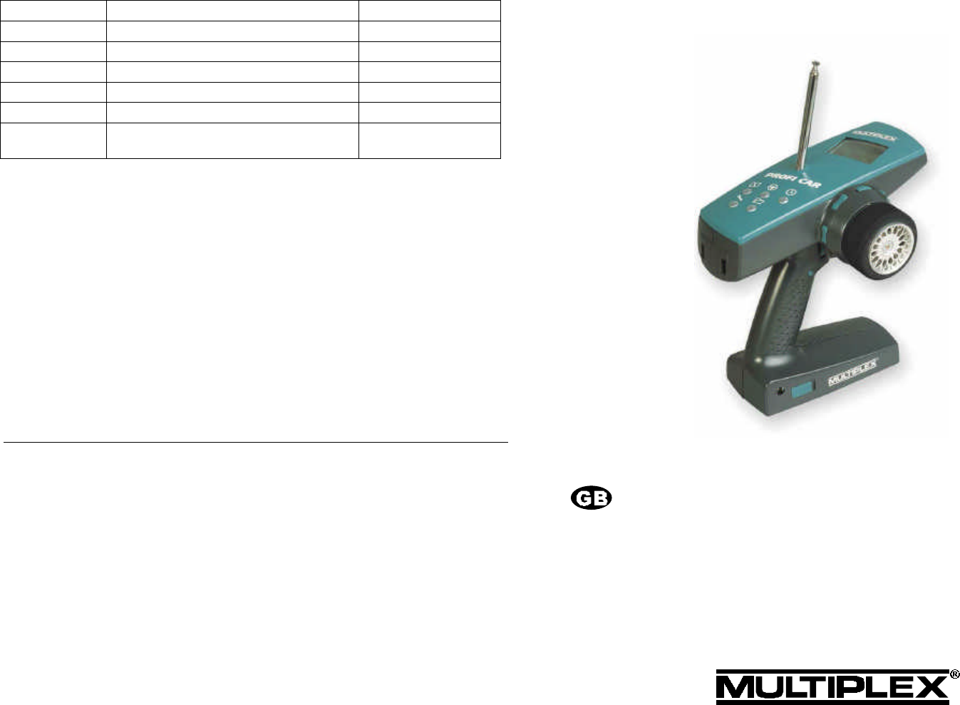
PROFI CAR 301
Operating instructions 21
ii
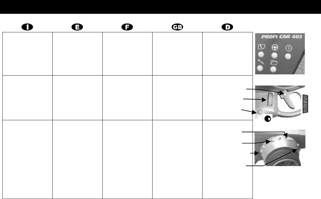
Vista generale Vista general Vue d’ensemble Overwiew Überblick
Tasti dei menu Teclas del menú Touches de menus Menu buttons Menü-Tasten
Grilletto El gatillo La gâchette Trigger duster Abzug
Vite del grilletto
Regolatore digitale
Tasto
Tornilla
Regulador digital
Tecla
Vis de réglage
Souris
Bouton poussoir
Loop screw
Digi adiustor
Handle button
Bügel-Schraube
Digi-Einsteller
Griff-Taste
Le trim Los trimados Les trims Trim rockers Trimm-Wippen
Sterzo
Gas minimo
Bloccaggio freno
Canale aggiunt. 3
Direcciòn
Gas ralenti
Bloqueo freno
Canal adicional 3
Direction
Gaz ralenti
Blocage du frein
Voie aux. 3
Steering
Idle trim
Brake lock point
Aux. channel 3
Lenkung
Leerlauf
Blockierpunkt Bremse
Zusatzfunktion
Ripetitione
Ripetitione automatico si
vengono premuti per
più di 1 sec.
Repeticiòn
Repetición automática
cuando pulsada
más de 1 segundo.
Repetition
Repetition automatique
si enfoncée
plus d’une seconde.
Repeat function
Automatic repeat when
held pressed for longer
than 1 sec.
Wiederholfunktion
Automatische Wieder-
holung wenn länger als 1
sec gedrückt wird.
i
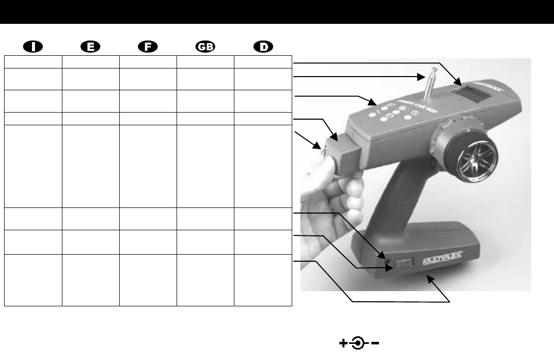
Vista generale Vista general Vue d’ensemble Overwiew Überblick
Display Display Display Screen Display
Antenna
(avvitata)
Antena
(atornillada)
Antenne
(vissé)
Aerial
(screw fitting)
Antenne
geschraubt
Tasti die
menu
Tecla del
menú
Touches de
menus
Menu buttons Menü-Tasten
Modulo Módulo HF Module HF RF module HF-Modul
Quarzo radio
ATTENZIONE
Utilizzare
solo quarzi
originali
MULTIPLEX
Cuarzo de la
emisora
!Atención!
Usar
solamente
cuarzos
originales de
MULTIPLEX
Quartz
d’émission
ATTENTION!
N’utilisez
que des
quartz
d’origine
MULTIPLEX
Transmitter
crystal
CAUTION!
Use only
genuine
MULTIPLEX
crystals
Sender-Quarz
ACHTUNG!
Nur Original-
MULTIPLEX
Quarz
verwenden.
Presa per
carica
Casquillo de
carga
Prise de
charge
Charge socket Ladebuchse
Interruttore
Acc./Spento
Interruptor de
ON/OFF
Interrupteur
Marche/Arrêt
ON/OFF
switch
Ein/Aus-
Schalter
Batteria radio
nelle parte
inferiore
Con protezi-
one termica!
Batería de la
emisora en el
pie
Con seguro
térmico!
Accu
d’émission
dans le pied
Avec sécurité
thermique!
Transmitter
battery in
base
With
thermal fuse
Senderakku
im Fuß
Mit Thermo-
sicherung!
Ladebuchse
Charge socket
Prise de charge 600 mA max.
Casquillo de carga
Presa di carica

21
Contents
1. Safety 22
2. Features and specification 23
3. The “instrument panel” (screen) 24
4. The basic principles 25
5. Switching on for the first time 26
5.1. Charging the transmitter battery (maximum charge current 1 A) 26
5.2. Charging the receiver battery 26
5.3. Fitting the transmitter crystal 26
5.4. Adjusting the trigger 26
5.5. Testing the transmitter 26
6. The STEERING LL 27
6.1. Adjusting the steering servo 27
6.2. Setting minimum steering travel 29
6.3. EXPO 29
6.4. Setting the steering trim increment (menu „T“) 30
7. The THROTTLE/BRAKE servo AA 30
7.1. Throttle and brake with EXPO 31
7.2. Signal norm, direction of rotation and travels for the throttle/brake servo 31
7.3. Idle trim 32
7.4. Trimming the brake lock point 32
8. Stopwatch and operating hours timer ºº 33
8.1. Activating the stopwatch (timer) 33
8.2. Stopwatch signal (race duration) 33
8.3. Checking and erasing the operating time 34
9. Model memories 11 34
9.1. Switching to a different model memory 34
9.2. Entering the model name 34
9.3. to return to the operating screen 35
10. Auxiliary function, servo 3 35
10.1. Setting the auxiliary channel mode (menu point “S-NORM”) 36
10.2. Adjusting auxiliary channel travel and centre (menu point “S-TRAV”) 36
11. The “toolbox” TT 36
11.1. AM-FM switching (menu „T“ , AM-FM) 36
11.2. Entering the owner’s name (menu „T“, NAME) 37
11.3. Selecting the screen language (menu „T“ , TEXT) 37
11.4. Setting the battery alarm threshold (menu „T“ , ALARM) 37
12. Tips on installing the receiving system in the model 38
13. Notes on using the system 38
13.1. Post Office regulations for the U.K. 38
13.2. Range checking 39
13.3. Care of the transmitter 39
13.4. Maintenance 40
14. PROFI CAR 301 menu structure 40

22
Dear customer,
Dear fellow-modeller,
We are delighted that you have decided to purchase a MULTIPLEX radio control system.
Your PROFI CAR 301 has all, what’s needed for ON- or OFF-ROAD models in 1:12, 1:10 and
1:8 scale.
Hardware, design and operation philosophy are the same as in the two „big“ radios (PROFI
CAR 403 and 707). Modifications have been made only, where required by an optimised
user-friendliness.
We wish you many hours of pleasure with your PROFI CAR.
Yours - the MULTIPLEX team
1. Safety
Radio-controlled models are not playthings!
The most important contribution to operational security and safety is your own: all
you have to do is handle your radio control system and model with due care and in a
responsible manner.
v Check all electrical and mechanical connections in the model at regular
intervals.
v Check regularly that all working parts are free-moving and devoid of slop.
v Carry out regular range checks (è 13.2, page 18).
v Before you switch on, ask other modellers at the trackside which channels
are already in.
v Extend the transmitter aerial to full length before running your model, and
check that it is firmly seated and in good condition.
v Check that you have selected the correct model memory for your model.
v Check all working systems before each run:
Are the servos moving in the correct direction?
Are the control travels set correctly?
v Are the transmitter and receiver batteries adequately charged, and in
serviceable, well maintained condition?
v Use genuine MULTIPLEX crystals, batteries and accessories exclusively.
v If any components of your receiving system are not covered by this manual,
read carefully the instructions supplied with them.
If you are in doubt about anything - don’t run your model. Check everything again in
peace and quiet, and locate and eliminate the cause. If you cannot solve the
problem, you will find your model shop and the MULTIPLEX Customer Service
department ready and willing to help you.
!! Read the notes in Section 13. concerning using the system!

23
2. Features and specification
AA Trigger
Servo - NORM, TRAVEL and CENTRE
EXPOnential effect for THROTTLE/BRAKE (progressive/degressive)
LL Steering
Servo - NORM, TRAVEL and CENTRE
EXPOnential STEERING curve (progressive/degressive)
MINimum TRAvel minimum steering travel
ºº Timer
TIMER (stopwatch) ON or OFF
SIGNAL function for stopwatch
Checking and erasing the OPERATING HOURS TIMER
TT „Onboard toolbox“
Selectable TRIM effect (fine/medium/coarse)
Selectable screen TEXT language (G, GB, F, I, Sp)
Transmitter NAME (owner’s name)
Battery monitor ALARM threshold
Servo 3 TRAVEL and centre (auxiliary function)
Servo 3 NORM mode (3 positions/flash/proportional)
Select modulation (AM/FM) for active model memory
11 3 model memories
GO TO a different model memory (change memory)
Enter model NAME
ERASE All (reset model memory)
Mechanics
Adjustable trigger, steering wheel with high-grip lining
Ergonomic controls in handle
Clearly arranged screen, angled towards the driver
Light weight ~ 600g incl. battery
Dimensions (W x H x D) 175 x 210 x 75 mm
Operating temperature range -15° C – +50° C
Signal transmission
Three channels (steering, throttle/brake, auxiliary function)
Selectable FM / AM modulation for each model memory
Plug-in RF module (40/41 MHz and 75 MHz))
Externally accessible plug-in transmitter crystal
Power supply
600 mAh, 6 cells battery
Charge socket in base. Battery includes integral thermal fuse
Current drain ~ 190 mA (~ 25 mA excl. RF module)
Operating time with 600 mAh battery ~ 2:45 hr
Variable battery alarm threshold 6,8 V to 7,2 V
24
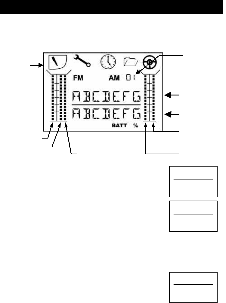
3. The “instrument panel” (screen)
The illustration below shows everything that the screen can display. What you
actually see at any one time depends on whether the stopwatch is active, and
whether you are currently programming the transmitter or using it.
You will find a few examples below the illustration.
Operating screen
Timer: OFF
If the stopwatch is not active, the first text line on the screen
shows the model name you have entered. Text line 2 shows the
operating voltage.
Timer: ON
The second text line displays the stopwatch. The timer is
started and stopped using the handle button. Holding the
button pressed in for longer than 1 second resets the
stopwatch to 00.0.
Special case: battery alarm with timer active
If one of the timer modes is active and the battery voltage falls to the alarm
threshold, the screen displays the current time and battery voltage together with
BATT, alternating at 2 second intervals.
When programming the transmitter
When you are setting up the transmitter the first text line
shows the selected menu point (example: signal norm for servo
1). The second line displays additional information, and the
value you have set or selected.
Auxilliary
function, servo 3
Steering travel
Idle
Steering trim
Brake
Text line 1
Number of active
model memory
Text line 2
BUGGY
7.4V
BATT
BUGGY
00:0
S-NORM
1: UN
Menu
symbols
25
4. The basic principles
The five menu buttons of the PROFI CAR are the key to all the adjustments you can
make. The symbols tell you the menu points to which each button provides access.
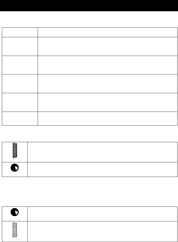
Menu button Menu function
A TRIGGER
Everything to do with throttle and brake
NORM, CENTRE, TRAVEL and EXPO for the THROTTLE/BRAKE servo
L STEERING
Adjust steering to suit the track / vehicle / driver
NORM, CENTRE, TRAVEL and EXPO for the STEERING servo
U TIMER
Switch stopwatch ON or OFF, set signal time
Check and erase operating hours timer
T TOOL
Basic transmitter settings
Set servo 3 mode
F MEMORY
Change, assign name, erase
Once you have found your way to the appropriate menu point, you use the digi-
adjustor and the handle button to complete the process.
DIGI-ADJUSTOR
Set values (travels, times, ...)
HANDLE BUTTON Confirm erasure and memory change
(hold pressed in for longer than 3 sec.)
Return to the operating screen; press any menu button other than the one you last
used.
When you see the operating screen (i.e. when you have completed your
adjustments), the functions of the handle button and the digi-adjustor are as follows:
HANDLE BUTTON
Operate stopwatch (if active)
DIGI-ADJUSTOR
Adjust steering travel

26
5. Switching on for the first time
5.1. Charging the transmitter battery (maximum charge current 1 A)
First connect the charge lead (Order No. 12 5023) to the charger, then connect the
charge lead to the transmitter.
Charging - important:
•• Automatic battery fuse
The battery in your PROFI CAR features an integral thermal fuse which protects the
pack if it is shorted, or if the charge current is excessive.
Use only genuine fuse-protected MULTIPLEX batteries!
!! If a short-circuit occurs and you eliminate it (or cut off the charge current), the
fuse cools down again in about one minute, and the battery is then ready for use
again.
•• Notes on charging techniques:
Standard (slow) charging is possible, and no special techniques are required.
If you wish to rapid-charge the battery using automatic termination, the charge
current must not exceed 600 mA, otherwise the fuse element may be triggered and
the charge process will be interrupted prematurely.
5.2. Charging the receiver battery
Read the charging notes printed on the battery. Do not exceed the charge currents
stated by the battery manufacturer!
5.3. Fitting the transmitter crystal
Transmitter crystals feature a blue sleeve, and the printed channel number is
preceded by “Tx” or “S”. The transmitter and receiver crystals must bear the same
channel number. The transmitter crystal is plugged into the RF module (-> illustration
on page i).
Please be very careful when handling crystals:
v Don’t drop them
v Don’t force them into the crystal socket
v Protect them from vibration in storage and in use
5.4. Adjusting the trigger
If you loosen the screw in the trigger, the bar can be adjusted to suit your “finger
diameter”.
CAUTION when tightening the screw: if you over-tighten it, the pressed-fit nut on
the other side may come loose!
5.5. Testing the transmitter
Now you can switch on the transmitter, connect the components of a receiving
system, and find out “what happens” when you operate the transmitter. All you need
are a receiver with servos connected to channels 1 and 2 and a receiver battery. If you
prefer to use a complete car for this, connect the steering servo to channel 1 and the
throttle/brake servo to channel 2.
27
6. The STEERING LL
The PROFI CAR offers the following facilities for setting up the steering function:
• Servo norm, centre and travel right/left (èè 6.1)
These settings are used to adjust the servo to match your car’s mechanical
system, and at the same time determine the maximum steering travel and the
centre setting for straight running.
• Steering MINTRA (MINimum TRAvel) (èè 6.2)
You can adjust the steering travel using the digi-adjustor while you are running
the car. This enables you to fine-tune the steering response to suit changing
course conditions or vehicle characteristics (e.g. tyre temperature). This menu
point allows you to define the smallest steering travel which you can set by
rotating the digi-adjustor. MINTRA avoids the danger of suddenly having no
steering control if you turn the adjustor too far by mistake. The smallest value
you can set is 30%.
• EXPO (èè 6.3
By applying EXPOnential to the steering function, you can make the steering
response of your car more or less sensitive around the centre position.
• Steering travel and trim increment (èè 6.4)
(„T“ menu, menu point „TRIM“)
The effect of trim rocker A (steering centre point) and the digi-adjustor (steering
travel) can be set to FINE (1% increments), MEDIUM (2% increments) or COARSE
(4% increments). The selected setting also applies to all other trim rockers.
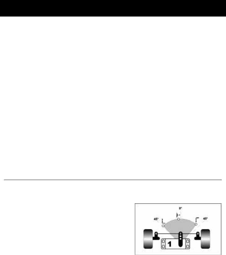
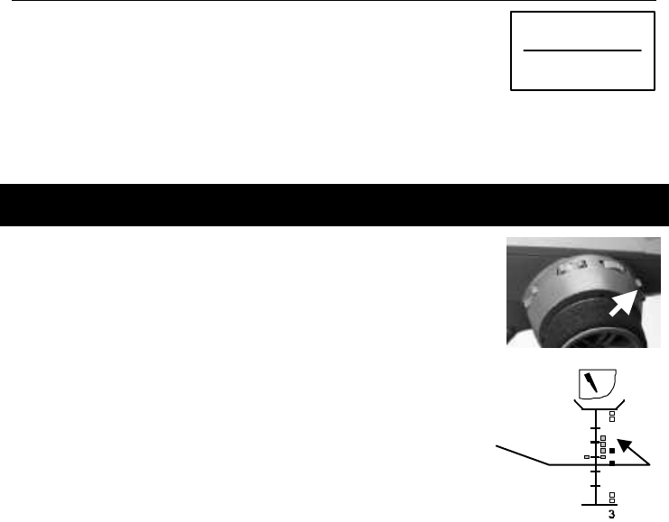
6.1. Adjusting the steering servo
The first step is to set the signal norm and the direction of rotation for the servo,
followed by the settings for left (LL), straight ahead (••) and right (ŒŒ). These basic
settings ensure that servo 1 (steering servo) is set up correctly to suit the
characteristics of your model.
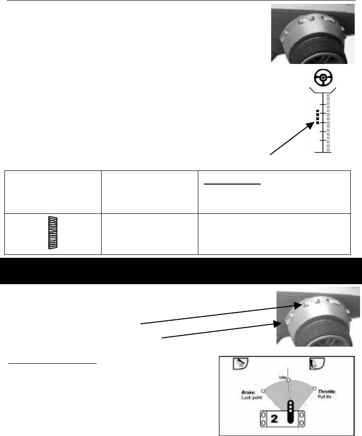
The drawing on the right shows an example of
the settings available in the “S-TRA” menu. The
stated angles (0°/45°) show what the servo “can
do”. The adjustments points „LL“ and „ŒŒ“ define
the maximum travel set for the steering servo.
To adjust either of these points you must turn
the steering wheel in the corresponding
direction. At the „••“point you determine the servo setting for “straight ahead”.
The “S-NORM” menu point is used to select the signal format (MULTIPLEX or
UNIVERSAL) and direction of rotation for the servo. “MULTIPLEX norm” means that
the pulse width for the centre position is 1.6 ms, and the full range is +/- 0.55 ms.
UNIVERSAL servos operate on 1.5 ms +/- 0.5 ms. If the selected signal format does not
match your servo, the centre position and travels will not be correct.
The “S-TRAV” menu point is used to set the centre position and steering travels for
right and left.
28
This is the procedure:
PREPARATION:
§ Set the steering trim to centre
Operate the ribbed steering trim rocker until
only the centre point is visible on the screen.
§ Set the steering travel to maximum
Operate the digi-adjustor until the maximum
steering travel is displayed on the screen.
LL press until
SS--NORMNORM
appears
S-NORM
1: MR
Select norm and
rotation using the
digi-adjustor
UN UNIVERSAL normal
UR UNIVERSAL reverse
MN MULTIPLEX normal
MR MULTIPLEX reverse
LL press until
SS--TRAVTRAV
appears
S-TRAV
1: •- 3
%
L
Select right, centre
and left by turning
the steering wheel,
then change using
the digi-adjustor
ŒŒ right 0 – 110 %
• • centre +/- 50 %
L L left 0 – 110 %
29
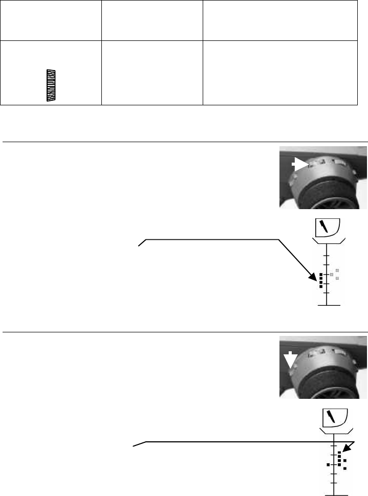
6.2. Setting minimum steering travel
You can adjust the steering travel during a race using the digi-adjustor, ensuring that
the response is optimum for the track and your car at all times.
Note: this only works when the operating screen is visible!
The vertical bar on the far right of the screen shows how much steering
travel you actually have available at any one time. In our example 2/3 of
the possible range between minimum and maximum is available.
It is important that you are able to set a minimum travel beyond which
the digi-adjustor cannot reduce the steering; this can be set within the
range 30% and 100%.
LL press until
MINMIN--TRTR
appears
Search for menu
point
MIN-TR
60
%
Set minimum travel Range: 30% to 100%
Default: 44%
' TIP !
The maximum steering travel must be defined by adjusting the mechanical set-up
for the steering servo (è6.1).
6.3. EXPO
EXPO alters the steering characteristics of your model. If you set positive values (e.g.-
50%), the steering travel will be reduced around centre, making your car easier to
steer in a straight line at high speed.
Negative EXPO values produce the opposite effect, making the steering response
more direct around centre.
LL press until
EXPOEXPO
appears
Search for menu
point
EXPO
70
%
Set Expo
Range: -100% to 100%
Increment: 5%
Default: 0%
30
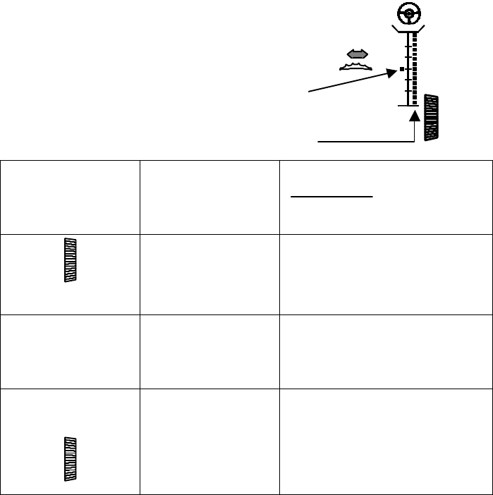
6.4. Setting the steering trim increment (menu „TT“)
The trim rocker for steering can easily be found “blind”
because its shape and ribbed surface are different from those
of the other rockers.
The steering trim can be used to adjust the centre position of
the steering servo by 28% in either direction. Each increment
offsets the centre by at least 1% (FINE) and at most 4%
(COARSE). You can select the size of the trim increment in the
TRIM menu point of the „T“ menu; the default setting is
MEDIUM (2%).
' NOTE: the setting which you choose here also applies to the
idle and brake trims, and the steering travel adjustment (digi-
adjustor).
A vertical bar on the screen shows the current trim position.
T , T , ... until
TRIMTRIM
appears
Search for menu
point
TRIM
MEDIUM
Select trim increment COARSE 4 %
MEDIUM 2 %
FINE 1 %
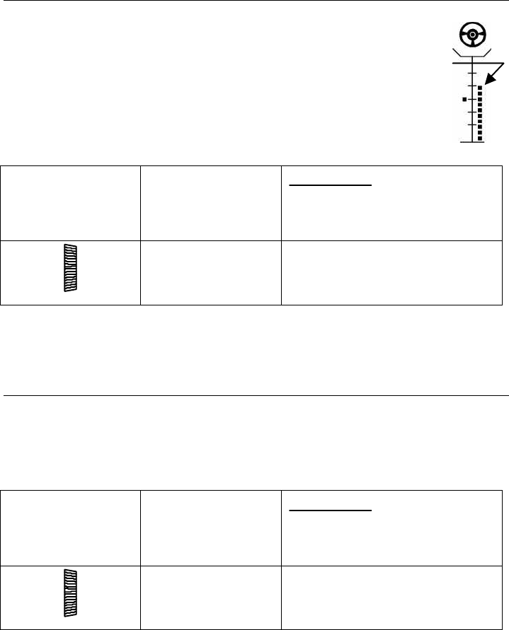
7. The THROTTLE/BRAKE servo AA
The PROFI car offers the following functions for throttle/brake:
v Throttle and brake with separate EXPO
v Idle trim
v Lock point trim
For the sake of clarity:
The diagram on the right shows the servo
positions which are assigned to the individual
points on the throttle-brake curve.
Full throttle is influenced solely by the travel you
set for the throttle/brake servo.
You can also adjust the idle setting while the car
is running by operating the trim rocker (see above). The basic setting is defined using
the CENTRE adjustment point for the throttle/brake servo.
The lock point can also be changed when the car is running. The basic setting is
defined by adjusting the travel of the throttle/brake servo.
LL
31
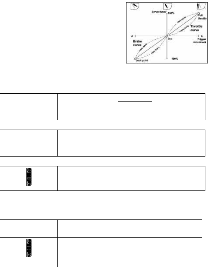
7.1. Throttle and brake with EXPO
You can apply EXPOnential to set the response of
the throttle/brake function to suit your personal
preference.
The diagram on the right shows the relationship
between the trigger movement and the servo
travel in graphic form.
If you set EXPO to 0%, the effect of the throttle/-
brake curve is linear. The dotted lines show how
EXPO can alter the two curves.
If you set EXPO to a negative value, the trigger will be more sensitive around the idle
position. Positive EXPO values produce an aggressive effect.
This is the procedure:
A , A , ...
EXPOEXPO
THRTHR
Search for menu
point for EXPO
THRottle
EXPO
THR 35
%
or:
A , A , ...
EXPOEXPO
BRKBRK
Search for menu
point for EXPO BRaKe
EXPO
BRK 27
%
then:
Set value Range: -100% to 100%
Default: 0%
Increment: 5%
7.2. Signal norm, direction of rotation and travels
for the throttle/brake servo
First set the signal norm and direction of rotation of the servo.
A , A , ...
SS--NORMNORM
Search for menu
point for servo norm
S-NORM
2: MR
Select norm and
direction using the
digi-adjustor
UN UNIVERSAL normal
UR UNIVERSAL reverse
MN MULTIPLEX normal
MR MULTIPLEX reverse
32
The next step is to define the basic settings for full throttle (LL), idle (••) and for the
lock point (ŒŒ). These settings ensure that servo 2 (throttle/brake servo) is set up
correctly to suit your model.
A press until
SS--TRAVTRAV
appears
S-TRAV
2: •- 3
%
A
Select the desired
point with the trigger,
then set using the
digi-adjustor
ŒŒ Lock point 0 – 110 %
•• Idle +/- 50 %
LL Full throttle 0 – 110 %
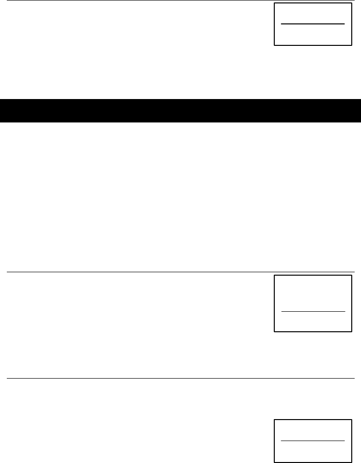
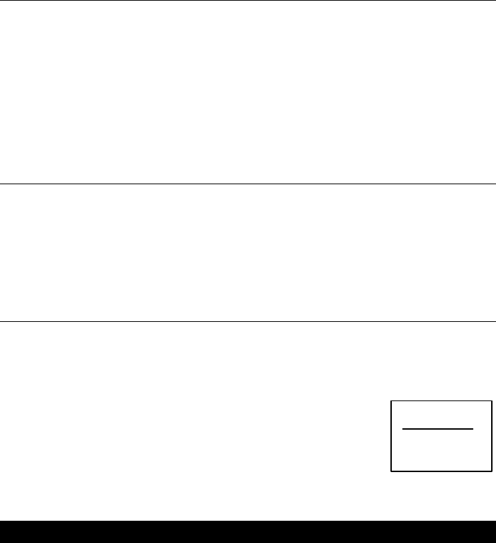
7.3. Idle trim
The idle trim can be used to compensate for changes in the
running characteristics of any car with an internal-combustion
motor, e.g. changes due to fluctuations in motor temperature.
Idle trim allows you to adjust the idle by 28% in either
direction. Each increment offsets the idle point by at least 1%
(fine) and at most 4% (coarse). You can select the size of the
trim increment in the “TRIM” menu point of the „T“ (è6.4,
page10). The default setting is MEDIUM (2%).
A vertical bar on the screen shows the current trim setting. In
the example on the right the idle has been offset in the
direction of “reduced throttle” by about half the full trim
range.
7.4. Trimming the brake lock point
The lock point of the brake tends to vary in the course of a
race, so we have provided a trim rocker which can be used to
compensate for these variations. The rocker affects the lock
point of the THROTTLE/BRAKE servo (servo 2).
The brake trim allows you to adjust the lock point by 28% in
either direction. Each increment offsets the idle by at least 1%
(fine) and at most 4% (coarse). You can select the size of the
trim increment in the “TRIM” menu point of the „T“ menu
(è 6.4, page 10). The default setting is MEDIUM (2%).
A vertical bar on the screen shows the current trim setting. In
the example on the right the lock point of the throttle/brake
servo has been offset in the direction of “greater brake effect”
by slightly less than half the full trim range.

33
8. Stopwatch and operating hours timer ºº
The PROFI CAR 301 provides the following timing facilities:
v Stopwatch (TIMER)
Start and stop the stopwatch using the handle button G, provided that the
function has already been switched on in the TIMER menu.
v Stopwatch SIGNAL
Audible signal which can be used to signal the end of a practice run, for
example (max. 20 min.).
v Operating hours timer (OPTIME)
This timer records the period of use of the transmitter battery, and it always
runs when the transmitter is switched on. You can erase the operating time
in the „º“OPTIME menu.
8.1. Activating the stopwatch (timer)
This is the procedure:
§ Search for the menu point TIMER with the º button
§ Select ON or OFF with the digi-adjustor
Press any menu button (except º) to return to the operating
screen.
The stopwatch is operated by the handle button G (START/STOP).
Resetting the stopwatch to 0:
The stopwatch is reset to 00.0 by holding the handle button G pressed in for longer
than 3 sec. You can only do this when the operating screen is displayed.
8.2. Stopwatch signal (race duration)
The stopwatch’s signal function is useful for practice purposes: you set the signal
time to the planned race duration (max. 20 min.). Once you start the stopwatch (by
pressing the handle button) you will hear the following signals:
X short tone every full minute,
every 10 sec. during the last minute
every second during the last 10 sec.
X X long tone when the set time is elapsed
This is the procedure for setting the signal time:
§ Search for the menu point SIGNAL with the º button
§ Rotate the digi-adjustor to adjust the flashing number
§ Press the handle button G to move the cursor to the
next character
Press any menu button (except º) to return to the operating screen.
TIMER
OFF
SIGNAL
19:59:9
min : sec : 1/10
34
8.3. Checking and erasing the operating time
In this menu point you can check and erase the recorded
operating time. To erase the value you must hold the handle
button G pressed in for longer than 3 sec; you will hear an
audible signal to confirm that the erasure has taken place.
§ Use the º button to search for the menu point OPTIME
The screen shows hours and minutes.
Press any menu button (except º) to return to the operating screen.
9. Model memories 11
The model memories store all the settings which you have entered for a particular
vehicle. The settings include:
v Modulation (FM/AM)
v Servo signal format, direction of rotation, centre, travels
v Settings for throttle, brake and steering
v Timer setting (ON or OFF) and signal setting
v Trims
If you switch off the transmitter, or switch to a different model memory, the data in
the active model memory is updated.
9.1. Switching to a different model memory
§ Use the 1 button to search for the menu point GO TO
§ Use the digi-adjustor to select the destination memory
The screen shows name, memory and trim settings.
§ Complete the change by holding the handle button
G pressed in for longer than 3 sec.
A long audible tone confirms that the change has been made, and the operating
screen appears again.
9.2. Entering the model name
A model name can consist of up to six letters, numbers or other characters. The
following characters are available:
ABCDEFGHIJKLMNOPQRSTUVWXYZ-0123456789
§ Use the 1 button to search for
the menu point MODEL
§ The first character flashes, and can be changed using
the digi-adjustor.
§ Press the handle button G to shift to the next
character, and from the last character back to the first one
Press any menu button (except 1) to return to the operating screen.
03
GO TO
STAMP
MODEL
MIRAGE
OPTIME
6:17
h:min
35
9.3. to return to the operating screen
This menu point is used to reset the model memory to the
factory default settings. These settings are:
Servo centre 0%, servo travels 100%
§ Use the 1 button to search for the menu point
ERASE ALL
§ Confirm the erasure by holding the G button pressed in for longer than 3
sec.
Press any menu button (except 1) to return to the operating screen.
10. Auxiliary function, servo 3
One special feature of the PROFI CAR 301 is that it can control a
third servo to provide an auxiliary function, e.g. for mixture
adjustment, two-speed gearbox etc. The auxiliary channel is
controlled by trim rocker 3.
Three different modes are available for auxiliary channel 3.
v 3P 3 positions (left, centre, right)
v FL flashing
v PR proportional (25 increments)
The screen shows the position of the auxiliary channel. The
default setting for the auxiliary channel is three-position mode.
You can adjust travel and centre for servo 3 in the menu point
“S-TRAV” in the ” T “menu (è 10.2).
This is how auxiliary channel 3 is used in its three modes:
§ “3P” mode (3 Positions)
If you press the same end of rocker 3 repeatedly, the servo switches between
centre and one end-point. If you press the other end of rocker 3, the servo
immediately moves to the opposite end-point.
§ “FL” mode (FLashing)
In flashing mode the servo switches automatically between centre and one
of the two end-points every 0.5 sec. The flashing is switched on and off by
pushing rocker 3.
§ “PR” mode (PRoportional)
Every time you press rocker 3, the servo position changes by one increment.
25 increments are available.
In practice, the best way to find out how these modes of operation work is simply to
try them out using a spare servo.
3
ERASE
ALL

36
10.1. Setting the auxiliary channel mode (menu point “S-NORM”)
The modes for the auxiliary channel are located at the point where you also set the
direction of rotation and signal format for this channel.
§ Use the „T“ button to search for the menu point “S-NORM”.
§ Select one of the modes: 3Position, FLashing or Proportional using the digi-
adjustor.
Press any menu button (except T ) to return to the operating screen.
10.2. Adjusting auxiliary channel travel and centre (menu point “S-TRAV”)
The steering wheel is used to select the servo position of the auxiliary channel which
you wish to adjust.
§ Use the „T“ button to search for the menu point “S-TRAV”.
§ Select left (L), centre (•) or right (Œ) with the steering wheel
§ Adjust the selected point using the digi-adjustor
Press any menu button (except T ) to return to the operating screen.
11. The “toolbox” TT
The “toolbox” is opened by pressing the T button. It contains the following
facilities:
v Settings which affect the whole transmitter
If you select one of these settings, the screen shows the symbol „--“ instead of the
memory number. This is intended to remind you that the selected settings apply to
the whole transmitter, i.e. they are not specific to a particular model memory. These
settings in detail are: owner’s name, screen language and battery alarm threshold
The following parameters can also be set, but they apply to each model memory
individually:
v Modulation (AM or FM)
v Basic servo settings (“S-NORM” and “S-TRAV”)
v Trim increment size
In this Section you will find all those settings which have not been covered in the
instructions so far.
11.1. AM-FM switching (menu „T“ , AMAM--FMFM)
The PROFI CAR transmitter is the world’s first to allow you to use AM (Amplitude
Modulation) and FM (Frequency Modulation) receivers without having to swap RF
modules. In the AM-FM menu point you can define which type of modulation is to be
used for each model memory separately.
37
§ Use the „T“ button to search for the menu point “AM-FM”.
§ Use the digi-adjustor to select the correct modulation to match the receiver
in that model.
Press any menu button (except T ) to return to the operating screen.
11.2. Entering the owner’s name (menu „T“, NAMENAME)
To identify your transmitter you can enter a 6-character name which appears briefly
on the screen when you switch the unit on. The following characters are available:
ABCDEFGHIJKLMNOPQRSTUVWXYZ-0123456789
§ Use the „T“ button to search for the menu point „NAME“.
§ The first character flashes, and can be changed using the digi-adjustor.
§ Use the handle button G to shift to the next character, and from the last
character back to the first one.
Press any menu button (except T) to return to the operating screen.
11.3. Selecting the screen language (menu „T“ , TEXTTEXT)
You can select any of five languages for the screen displays:
German, English, French, Italian, Spanish
§ Use the T button to search for the menu point „TEXT“.
§ Select the language using the digi-adjustor.
Press any menu button (except T) to return to the operating screen.
11.4. Setting the battery alarm threshold (menu „T“ , ALARMALARM)
The battery alarm threshold can be adjusted within the range 6.80 V to 7.20 V in 0.05
V increments. The default setting for the alarm threshold is 7.00 V.
The higher the threshold you set, the more reserve energy is left between the alarm
being triggered, and the battery being finally exhausted.
This is the procedure:
§ Use the T button to search for
the menu point „ALARM“.
§ Use the digi-adjustor to alter the alarm threshold in 0.05
V increments between 6.80 V and 7.20 V.
Press any menu button (except T) to return to the operating screen.
ALARM
6.80V
BATT

38
12. Tips on installing the receiving system in the model
There is usually very little scope for changing the arrangement of the receiving
system in a model car. However, please read and observe our recommendations
regarding deploying the aerial.
The following points are particularly important:
• Keep the receiver as far away as possible from:
- electric motors
- electrical ignition systems
- servos
- batteries
- cables (especially those carrying high currents)
• Run the aerial vertically up and out of the model in as straight a line as possible
and by the shortest route.
• Do not shorten the aerial!
• Do not wind or coil up the aerial and stow it inside the model.
• Do not deploy the aerial inside model parts or attached to model parts which are
reinforced with carbon fibre (shielding).
• Protect the receiver from vibration
(wrap it in foam and stow it loosely in the model).
' TIP ! if you model is powered by an electric motor:
Keep the receiving system as far as possible from the power system, as the high
currents in the power system can generate interference. Ensure that electric drive
motors are correctly suppressed.
!! Carry out a particularly thorough range check before the first run (èè .13.2).
13. Notes on using the system
13.1. Post Office regulations for the U.K.
The frequency bands available for radio controlled Surface models are 40.665 to
40.955 MHz (Channels 50 - 79 incl.).
!! Please pay attention to the attachment “Directive R&TTE 1999/5/EC”.
As of 1 January 1981 model control equipment was exempted from the licensing
requirements of the Wireless Telegraphy Act 1949. This simply means that no licence
is required to operate RC equipment in the U.K. If you need further information
please contact:
The Low Power Radio Section, Radiocommunications Agency
Room 712, Waterloo Bridge House, Waterloo Road, London SE1 8UA

39
13.2. Range checking
The range check makes a really important contribution to the operational security
and safety of your model. We have developed a test procedure based on our own
experience and measurements, which will always keep you on the safe side.
§ Collapse the transmitter aerial completely, and hold the transmitter as if
operating a model.
§ The check must be carried out with the motor running.
Ask a friend to hold the model, or pack it up so that the steering and driven
wheels are free to move.
§ There must be no large metal objects (cars, wire fences, etc.) in the vicinity.
§ There is no point in carrying out the check if there are other transmitters
switched on - even on other channels.
§ Switch on the transmitter and receiver, and check that the model responds
correctly and immediately to all control commands, without carrying out
any uncontrolled movements, when the transmitter is about 30 m from the
model.
' TIP !
Poor effective range may be due to any of the following problems:
v Inadequate suppression of electric power systems and ignition systems.
v Aerial wire damaged, too short (less than 40 cm) or poorly installed.
v Environmental effects (damp ground, shielding by metal fences, etc.).
If radio range with the aerial collapsed is not sufficient, and you are unable to identify
any of the potential problems stated above, repeat the check with the aerial
extended. The safe operating distance between transmitter and model should now
be around 1.5 times the actual required radius of action.
!! If you have any doubts, don’t run your model! Check everything again in peace
and quiet, so that you can locate and eliminate the problem reliably!
13.3. Care of the transmitter
Protect your transmitter from mechanical damage, temperatures above 60°C (direct
sunshine in a car), damp, solvents, fuel, exhaust residues and dust. Bear in mind that
condensation may occur inside the transmitter if it is subjected to a swift change of
temperature (e.g. when taken from a warm workshop to a cold car). Condensation
may prevent the transmitter working properly or at all. If this should happen, allow
the transmitter plenty of time to adjust to the new temperature, and be sure to carry
out a particularly thorough range test. Check that the transmitter is completely dry,
including the interior (battery compartment), before you switch it on.
Cleaning the transmitter
The best method of removing dust is to use a soft paintbrush. The case can be
cleaned with a slightly damp cloth and a mild household cleaning agent.
!! Take great care that no liquids get inside the transmitter.

40
13.4. Maintenance
Your transmitter contains no parts which require maintenance.
!! However, we do recommend that you carry out regular range checks, and check
that all functions are working correctly.
What to do if you have queries, or if problems arise?
First ask your local model shop for advice.
The last page includes a list of our Service Centres.
For technical queries, or questions regarding the use of our transmitters, you can ring
the MULTIPLEX-Hotline +49-7233-7343. You can also reach us by e-mail under
TECHNIK@multiplex-rc.de
14. PROFI CAR 301 menu structure
This is the menu structure of the PROFI CAR 301:
AA LL ºº TT FF
S-NORM S-NORM TIMER TRIM GO TO
Direction of rot. +
signal format for
thr./brake servo
Direction of rot. +
signal format for
steering servo
Stopwatch ON
and OFF
Trim increments,
COARSE, MEDIUM
or FINE
Switch to a
different model
memory
S-TRAV S-TRAV SIGNAL TEXT MODEL
Centre and travels
for throttle/brake
Centre and travels
for steering
Set signal time Screen text
language
Enter model name
EXPO
THR
EXPO OPTIME NAME ERASE
ALL
EXPO for throttle EXPO for steering Check/erase
oper. hours timer
Transmitter
owner’s name
Erase model
memory
EXPO MIN-TR ALARM
BRK
EXPO for brake Minimum steering
travel
Alarm threshold
for battery alarm
S-TRAV
Centre and travels
for servo 3
S-NORM
Operating mode
for servo 3
AM-FM
Change
modulation
