Multiquip High Chair Wm45Hce Users Manual
WM45HCE to the manual 40b2fb31-24de-4a8f-9366-4b431d9f738e
2015-02-09
: Multiquip Multiquip-Multiquip-High-Chair-Wm45Hce-Users-Manual-558323 multiquip-multiquip-high-chair-wm45hce-users-manual-558323 multiquip pdf
Open the PDF directly: View PDF ![]() .
.
Page Count: 40

OPERATION AND PARTS MANUAL
THIS MANUAL MUST ACCOMPANY THE EQUIPMENT AT ALL TIMES.
To find the latest revision of this
publication, visit our website at:
www.multiquip.com
SERIES
MODEL WM45HCE
PLASTER/MORTAR MIXER
(Honda GX160UT1HX2 Gasoline Engine)
Revision #0 (02/04/13)

PAGE 2 — WM45HCE PLASTER/MORTAR MIXER • OPERATION AND PARTS MANUAL — REV. #0 (02/04/13)
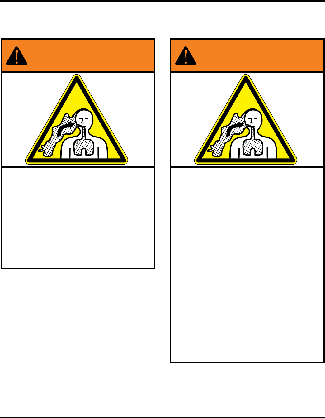
FUEL AND CHEMICAL WARNING
Gasoline engine exhaust and some of
its constituents, and some dust
created by power sanding, sawing,
grinding, drilling and other
construction activities contain
chemicals know to cause cancer, birth
defects and other reproductive harm.
Some examples of these chemicals are:
Lead from lead-based paints
Crystalline silica from bricks
Cement and other masonry products
Arsenic and chromium from chemically
treated lumber
Your risk from these exposures varies,
depending on how often you do this
type of work. To reduce your exposure
to these chemicals: work in a
well-ventilated area, and work with
approved safety equipment, such as
dust masks that are specially designed
to filter out microscopic particles.
ALWAYS
WM45HCE PLASTER MORTAR MIXER • OPERATION AND PARTS MANUAL — REV. #0 (02/04/13) — PAGE 3
Grinding/cutting/drilling of masonry, concrete, metal and
other materials with silica in their composition may give
off dust or mists containing crystalline silica. Silica is a
basic component of sand, quartz, brick clay, granite and
numerous other minerals and rocks. Repeated and/or
substantial inhalation of airborne crystalline silica can
cause serious or fatal respiratory diseases, including
silicosis. In addition, California and some other
authorities have listed respirable crystalline silica as a
substance known to cause cancer. When cutting such
materials, always follow the respiratory precautions
mentioned above.
WARNING
Grinding/cutting/drilling of masonry, concrete, metal and
other materials can generate dust, mists and fumes
containing chemicals known to cause serious or fatal
injury or illness, such as respiratory disease, cancer,
birth defects or other reproductive harm. If you are
unfamiliar with the risks associated with the particular
process and/or material being cut or the composition of
the tool being used, review the material safety data
sheet and/or consult your employer, the material
manufacturer/supplier, governmental agencies such as
OSHA and NIOSH and other sources on hazardous
materials. California and some other authorities, for
instance, have published lists of substances known to
cause cancer, reproductive toxicity, or other harmful
effects.
Control dust, mist and fumes at the source where
possible. In this regard use good work practices and
follow the recommendations of the manufacturers or
suppliers, OSHA/NIOSH, and occupational and trade
associations. Water should be used for dust
suppression when wet cutting is feasible. When the
hazards from inhalation of dust, mists and fumes cannot
be eliminated, the operator and any bystanders should
always wear a respirator approved by NIOSH/MSHA for
the materials being used.
WARNING
SILICOSIS WARNING RESPIRATORY HAZARDS
SILICOSIS/RESPIRATORY WARNINGS

PAGE 4 — WM45HCE PLASTER/MORTAR MIXER • OPERATION AND PARTS MANUAL — REV. #0 (02/04/13)
TABLE OF CONTENTS
WM45HCE PLASTER/MORTAR
MIXER
Fuel And Chemical Warnings .................................. 2
Silicosis/Respiratory Warnings ................................ 3
Table Of Contents .................................................... 4
Parts Ordering Procedures ...................................... 5
Safety Information ................................................ 6-9
Specifications ........................................................ 10
Dimensions ............................................................ 11
General Information ............................................... 12
Components .......................................................... 13
Basic Engine .......................................................... 14
Pre-Inspection (Engine/Mixer) ............................... 15
Initial Start-Up (Engine) .................................... 16-17
Maintenance (Engine) ...................................... 18-19
Maintenance (Mixer) ......................................... 20-21
Troubleshooting (Engine) ....................................... 22
Troubleshooting (Engine/Mixer) ............................. 23
Explanation Of Code In Remarks Column............. 24
Suggested Spare Parts ......................................... 25
NOTICE
Specifications and part numbers are subject to change
without notice.
Component Drawings
Nameplate and Decals ..................................... 26-27
Steel Tub Assembly .......................................... 28-29
Paddle Shaft Assembly ..................................... 30-31
Frame Assembly ............................................... 32-33
Engine Cover Assembly. ................................... 34-35
Engine/Guard Assembly ................................... 36-37
Terms And Conditions Of Sale — Parts ................ 38

WM45HCE PLASTER MORTAR MIXER • OPERATION AND PARTS MANUAL — REV. #0 (02/04/13) — PAGE 5
PARTS ORDERING PROCEDURES
www.multiquip.com
Ordering parts has never been easier!
Choose from three easy options:
WE ACCEPT ALL MAJOR CREDIT CARDS!
When ordering parts, please supply:
❒ Dealer Account Number
❒ Dealer Name and Address
❒ Shipping Address (if different than billing address)
❒ Return Fax Number
❒ Applicable Model Number
❒ Quantity, Part Number and Description of Each Part
❒ Specify Preferred Method of Shipment:
✓ UPS/Fed Ex ✓ DHL
■ Priority One ✓ Truck
■ Ground
■ Next Day
■ Second/Third Day
If you have an MQ Account, to obtain a Username
and Password, E-mail us at: parts@multiquip.
com.
To obtain an MQ Account, contact your
District Sales Manager for more information.
Order via Internet (Dealers Only):
Order parts on-line using Multiquip’s SmartEquip website!
■ View Parts Diagrams
■ Order Parts
■ Print Specification Information
Note: Discounts Are Subject To Change
Goto www.multiquip.com and click on
Order Parts to log in and save!
Use the internet and qualify for a 5% Discount
on Standard orders for all orders which include
complete part numbers.*
Order via Fax (Dealers Only):
All customers are welcome to order parts via Fax.
Domestic (US) Customers dial:
1-800-6-PARTS-7 (800-672-7877)
Fax your order in and qualify for a 2% Discount
on Standard orders for all orders which include
complete part numbers.*
Order via Phone: Domestic (US) Dealers Call:
1-800-427-1244
Best Deal!
International Customers should contact
their local Multiquip Representatives for
Parts Ordering information.
Non-Dealer Customers:
Contact your local Multiquip Dealer for
parts or call 800-427-1244 for help in
locating a dealer near you.
Note: Discounts Are Subject To Change
Effective:
January 1st, 2006
NOTICE
All orders are treated as Standard Orders and will
ship the same day if received prior to 3PM PST.
PAGE 6 — WM45HCE PLASTER/MORTAR MIXER • OPERATION AND PARTS MANUAL — REV. #0 (02/04/13)
SAFETY INFORMATION
Do not operate or service the equipment before reading
the entire manual. Safety precautions should be followed
at all times when operating this equipment.
Failure to read and understand the safety
messages and operating instructions could
result in injury to yourself and others.
SAFETY MESSAGES
The four safety messages shown below will inform you
about potential hazards that could injure you or others. The
safety messages specifi cally address the level of exposure
to the operator and are preceded by one of four words:
DANGER, WARNING, CAUTION or NOTICE.
SAFETY SYMBOLS
Potential hazards associated with the operation of this
equipment will be referenced with hazard symbols which
may appear throughout this manual in conjunction with
safety messages.
DANGER
Indicates a hazardous situation which, if not avoided,
WILL result in DEATH or SERIOUS INJURY.
WARNING
Indicates a hazardous situation which, if not avoided,
COULD result in DEATH or SERIOUS INJURY.
CAUTION
Indicates a hazardous situation which, if not avoided,
COULD result in MINOR or MODERATE INJURY.
NOTICE
Addresses practices not related to personal injury.
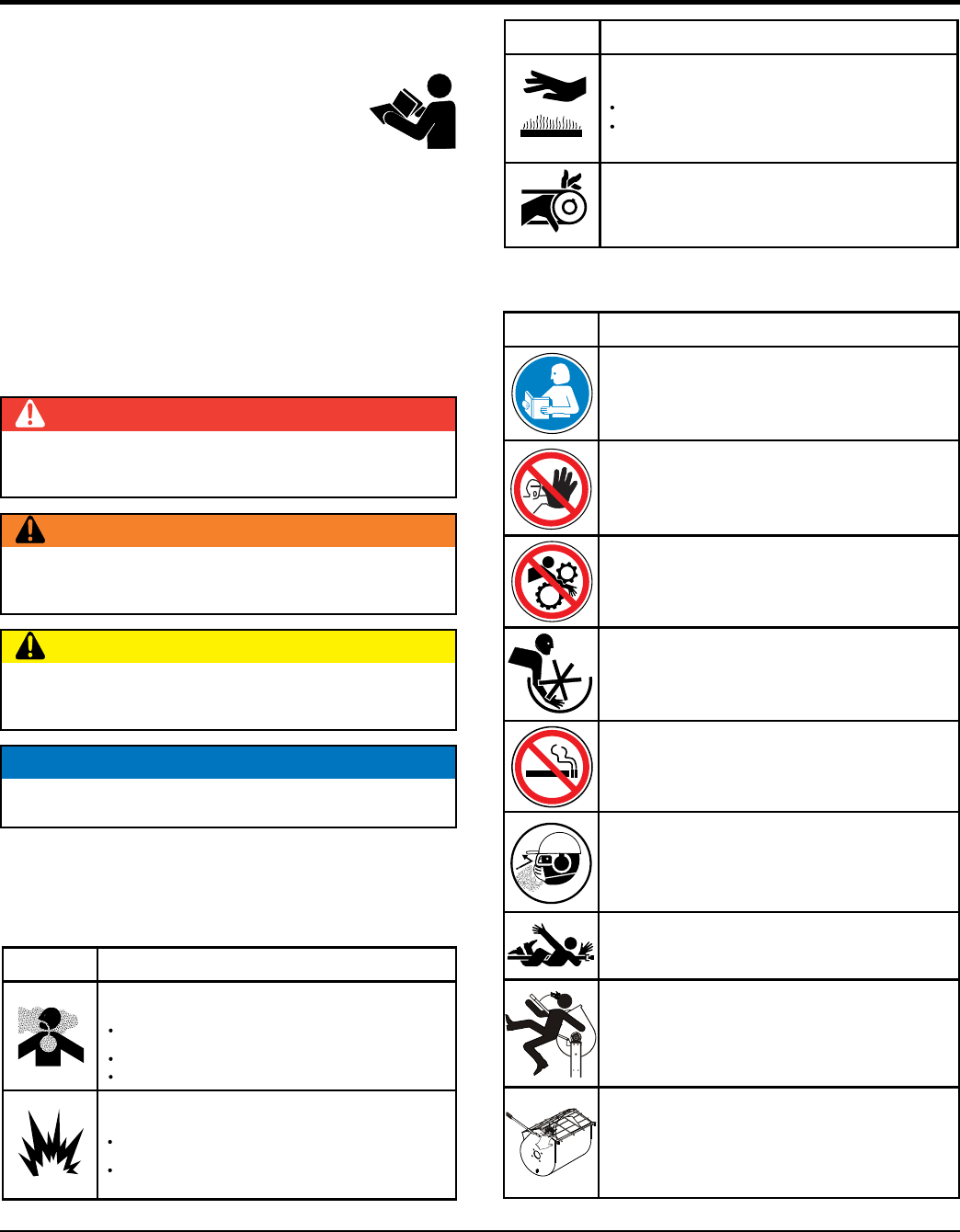
Inhaling exhaust fumes can result in severe
injury or death.
Only operate equipment in well ventilated areas.
inhale exhaust gases/fumes.DO NOT
WARNING
Lethal Exhaust Gas Hazard
Gasoline fuel can cause fire or explosion. Stop
engine before refueling.
Keep cigarettes, sparks and flames away from hot
surfaces.
WARNING
Explosive Fuel Hazard
SYMBOL SAFETY HAZARD
Warning decals associated with the operation of this
equipment are defi ned below:
HOT PARTS can burn skin.
CAUTION
Burn Hazard
touch hot parts. Allow machine a sufficient
amount of time to cool before performing maintenance.
DO NOT
SYMBOL SAFETY HAZARD (CONTINUED)
NEVER operate this equipment with guards removed.
Keep hands clear.
WARNING
Guard Hazard
To avoid injury you must read and understand
operator’s manual before using this machine.
This machine to be operated by qualified personnel.
Ask for training as needed.
WARNING
WARNING
Read Manual
NEVER operate this equipment with guards removed.
Keep hands clear.
WARNING
Training
Guard Hazard
DECAL SAFETY HAZARD
smoke around or near this equipment.DO NOT
WARNING
Fire Hazard
wear appropriate dust mask along with
hearing and eye protection.
ALWAYS
WARNING
Inhalation Hazard
WARNING
Entanglement Hazard
Stand clear of rotating blades.
WARNING
Kickback Hazard
Stand clear of drum handle when blades are
rotating.
WARNING
Crush Hazard
ALWAYS keep hands clear of safety grate when
closing.
Moving blades can cut and crush. operate
equipment with hands inside drum.
NEVER
WARNING
Rotating Parts Hazard
WM45HCE PLASTER MORTAR MIXER • OPERATION AND PARTS MANUAL — REV. #0 (02/04/13) — PAGE 7
SAFETY INFORMATION
GENERAL SAFETY
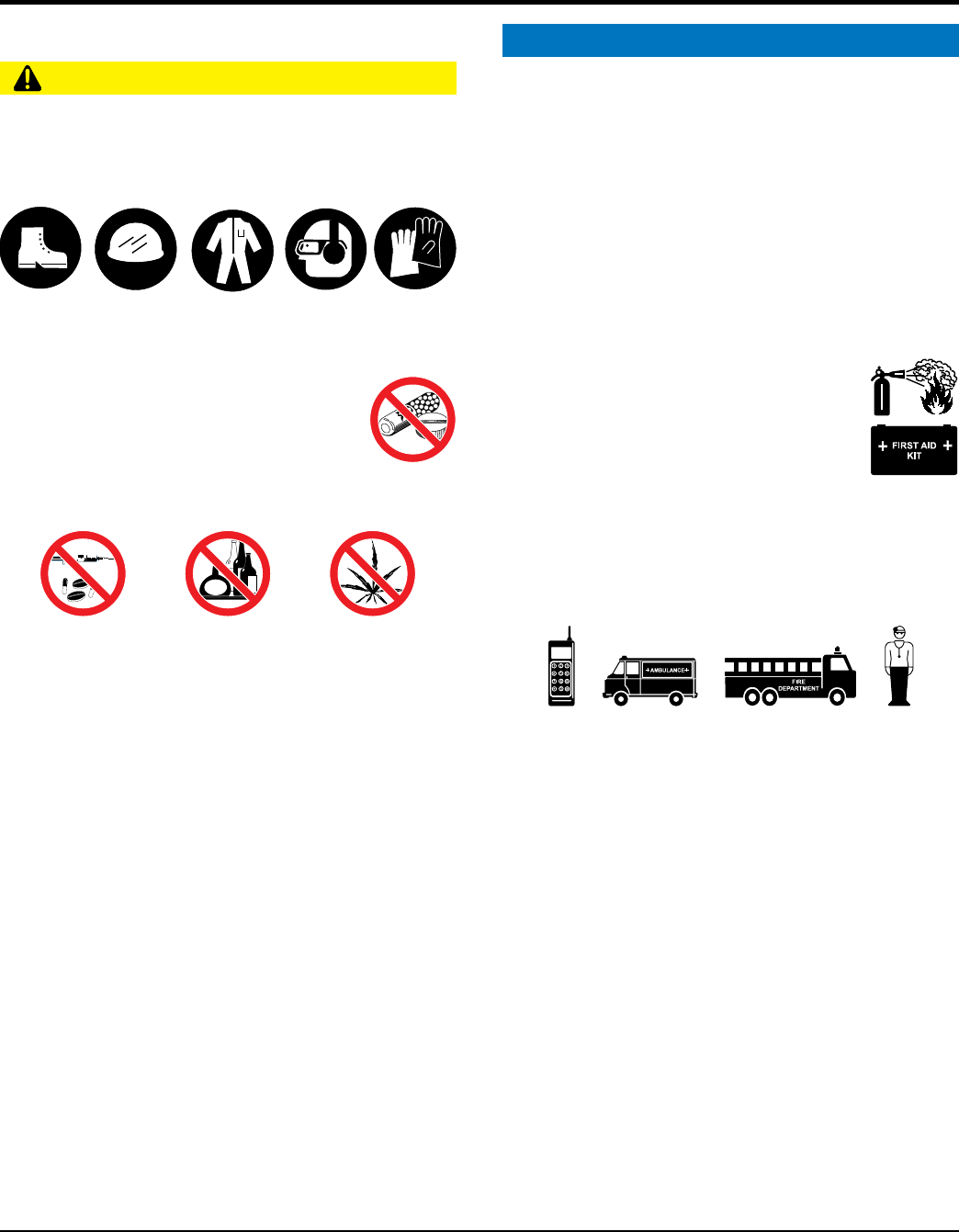
CAUTION
NEVER operate this equipment without proper protective
clothing, shatterproof glasses, respiratory protection,
hearing protection, steel-toed boots and other protective
devices required by the job or city and state regulations.
Avoid wearing jewelry or loose fi tting clothes that may
snag on the controls or moving parts as this can cause
serious injury.
NEVER operate this equipment when not
feeling well due to fatigue, illness or when
under medication.
NEVER operate this equipment under the
infl uence of drugs or alcohol.
ALWAYS clear the work area of any debris, tools, etc.
that would constitute a hazard while the equipment is
in operation.
ALWAYS check the equipment for loosened threads or
bolts before starting.
DO NOT use the equipment for any purpose other than
its intended purposes or applications.
NOTICE
This equipment should only be operated by trained and
qualifi ed personnel 18 years of age and older.
Whenever necessary, replace nameplate, operation and
safety decals when they become diffi cult read.
Manufacturer does not assume responsibility for any
accident due to equipment modifi cations. Unauthorized
equipment modifi cation will void all warranties.
NEVER use accessories or attachments that are not
recommended by Multiquip for this equipment. Damage
to the equipment and/or injury to user may result.
ALWAYS know the location of the nearest
fi re extinguisher.
ALWAYS know the location of the nearest
fi rst aid kit.
ALWAYS know the location of the nearest phone or
keep
a phone on the job site.
Also, know the phone numbers
of the nearest ambulance, doctor and
fi re department.
This information will be invaluable in the case of an
emergency.
PAGE 8 — WM45HCE PLASTER/MORTAR MIXER • OPERATION AND PARTS MANUAL — REV. #0 (02/04/13)
SAFETY INFORMATION
MIXER SAFETY
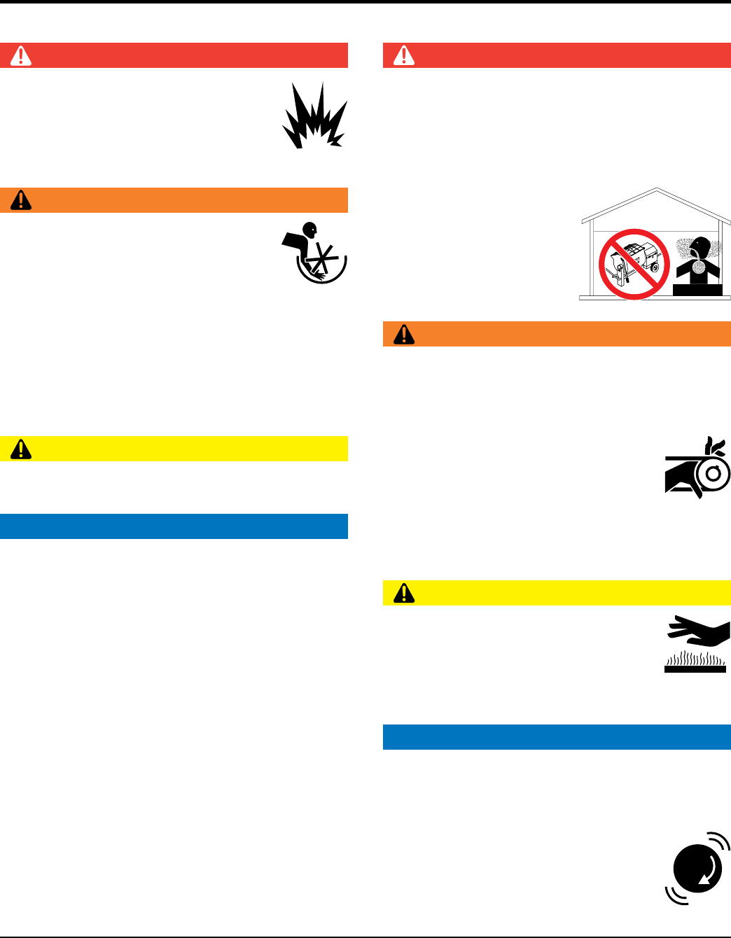
DANGER
NEVER operate the equipment in an explosive
atmosphere or near combustible materials. An
explosion or fi re could result causing severe
bodily harm or even death.
DO NOT mix fl ammable or explosive substances.
WARNING
NEVER place your hands inside the drum
while starting or operating this equipment.
NEVER disconnect any emergency
or safety devices. These devices are
intended for operator safety. Disconnection of these
devices can cause severe injury, bodily harm or even
death. Disconnection of any of these devices will void
all warranties.
Before operating mixer, ensure that safety grate is in
position and correctly fi tted.
CAUTION
NEVER lubricate components or attempt service on a
running machine.
NOTICE
ALWAYS keep the machine in proper running condition.
ALWAYS ensure mixer is on level ground before mixing.
Fix damage to machine and replace any broken parts
immediately.
DO NOT tip mixer onto drum mouth when the drum is
rotating.
Ensure the drum is rotating while fi lling and emptying
the drum.
ALWAYS store equipment properly when it is not being
used. Equipment should be stored in a clean, dry location
out of the reach of children and unauthorized personnel.
ENGINE SAFETY
DANGER
Engine fuel exhaust gases contain poisonous carbon
monoxide. This gas is colorless and odorless, and can
cause death if inhaled.
The engine of this equipment requires an adequate
free fl ow of cooling air. NEVER
operate this equipment
in any enclosed or narrow
area where free fl ow of the
air is restricted. If the air
fl ow is restricted it will cause
injury to people and property
and serious damage to the
equipment or engine.
WARNING
DO NOT place hands or fingers inside engine
compartment when engine is running.
NEVER operate the engine with heat shields or
guards removed.
Keep fi ngers, hands hair and clothing away
from all moving parts to prevent injury.
DO NOT remove the engine oil drain plug
while the engine is hot. Hot oil will gush out of the oil
tank and severely scald any persons in the general area
of the mixer.
CAUTION
NEVER touch the hot exhaust manifold,
muffl er or cylinder. Allow these parts to cool
before servicing equipment.
Make certain the operator knows how to and is capable
of turning the engine OFF in case of an emergency.
NOTICE
NEVER
run engine without an air fi lter or with a dirty air
fi lter. Severe engine damage may occur. Service air fi lter
frequently to prevent engine malfunction.
NEVER tamper with the factory settings
of the engine or engine governor. Damage
to the engine or equipment can result
if operating in speed ranges above the
maximum allowable.
DANGEROUS
GAS FUMES
WM45HCE PLASTER MORTAR MIXER • OPERATION AND PARTS MANUAL — REV. #0 (02/04/13) — PAGE 9
SAFETY INFORMATION
FUEL SAFETY
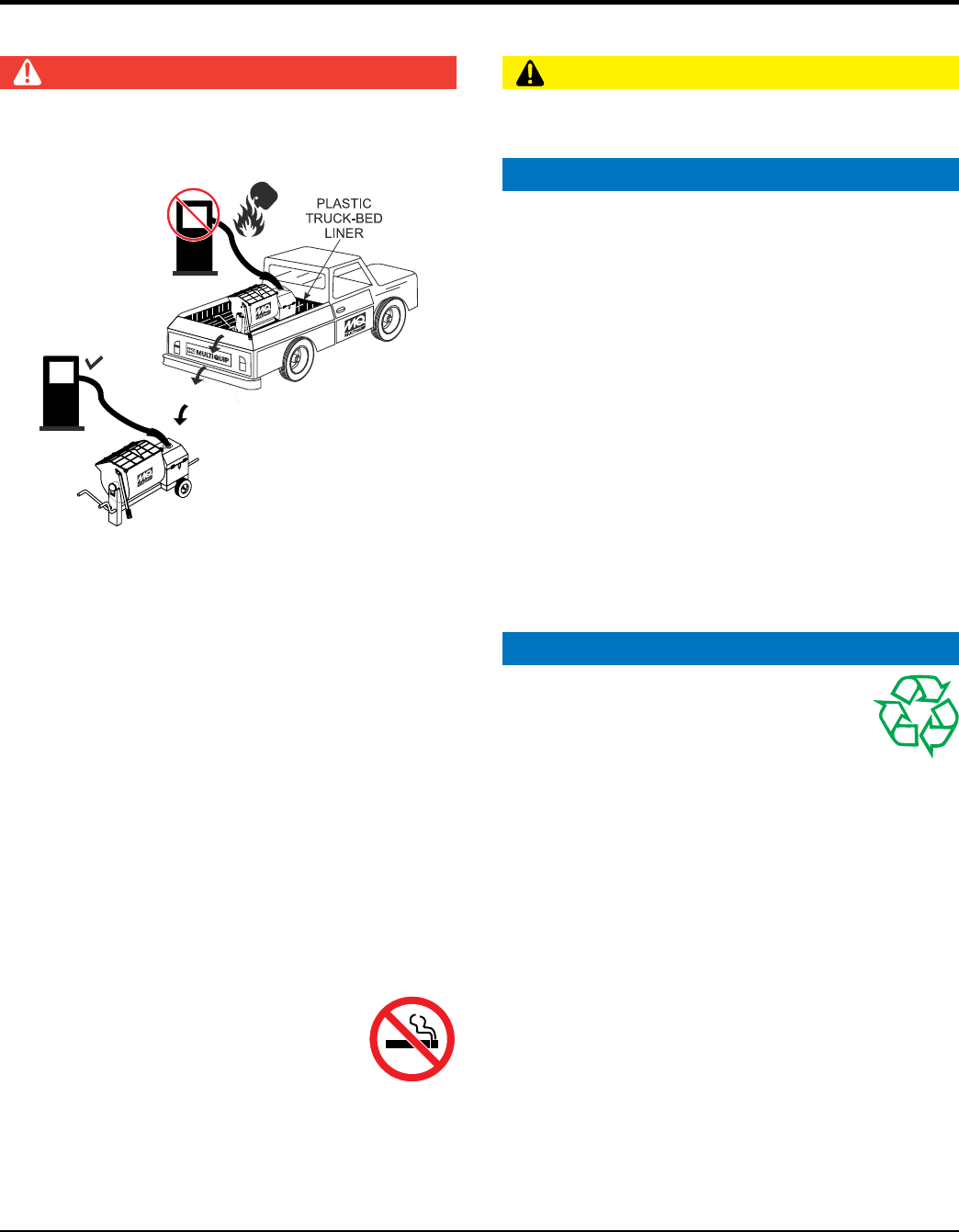
DANGER
DO NOT add fuel to equipment if it is placed inside truck
bed with plastic liner. Possibility exists of explosion or
fi re due to static electricity.
DO NOT start the engine near spilled fuel or combustible
fl uids. Fuel is extremely fl ammable and its vapors can
cause an explosion if ignited.
ALWAYS refuel in a well-ventilated area, away from
sparks and open fl ames.
ALWAYS use extreme caution when working with
fl ammable liquids.
DO NOT fi ll the fuel tank while the engine is running
or hot.
DO NOT overfi ll tank, since spilled fuel could ignite if it
comes into contact with hot engine parts or sparks from
the ignition system.
Store fuel in appropriate containers, in well-ventilated
areas and away from sparks and fl ames.
NEVER use fuel as a cleaning agent.
DO NOT smoke around or near the
equipment. Fire or explosion could result
from fuel vapors or if fuel is spilled on a
hot engine.
FUEL
FUEL
TRANSPORTING SAFETY
CAUTION
NEVER
allow any person or animal to stand underneath
the equipment while lifting.
NOTICE
ALWAYS
make sure forklift forks are inserted into pockets
(if applicable) as far as possible when lifting the mixer.
ALWAYS shutdown engine before transporting.
NEVER lift the equipment while the engine is running.
Tighten fuel tank cap securely and close fuel cock to
prevent fuel from spilling.
DO NOT lift machine to unnecessary heights.
ALWAYS tie down equipment during transport by
securing the equipment with rope.
NEVER
tip the engine to extreme angles during lifting as
it may cause oil to gravitate into the cylinder head, making
the engine start diffi cult.
ENVIRONMENTAL SAFETY
NOTICE
Dispose of hazardous waste properly.
Examples of potentially hazardous waste
are used motor oil, fuel and fuel fi lters.
DO NOT use food or plastic containers to dispose of
hazardous waste.
DO NOT
pour waste, oil or fuel directly onto the ground,
down a drain or into any water source.

PAGE 10 — WM45HCE PLASTER/MORTAR MIXER • OPERATION AND PARTS MANUAL — REV. #0 (02/04/13)
SPECIFICATIONS
Table 1. Mixer Specifications
Capacity 4.0 cu. ft (113 liters)
Bag Capacity 1-1/2 to 2-1/2 bags
Weight 380 lbs. (172 kg.)
Height W/Dump Handle 47 in. (119 cm.)
Discharge Height 7.5 in. (19 cm.)
Drive Gear
Dump Action Manual
Table 2. Engine Specifications
Engine
Model Honda GX160UT1HX2
Type Air-cooled 4 stroke, Single Cylinder,
OHV, Horizontal Shaft Gasoline Engine
Bore X Stroke 2.70 in. X 1.80 in.
(68 mm x 45 mm)
Displacement 9.9 cu. in. (163 cc)
Max Output 5.5 H.P./4000 R.P.M.
Fuel Tank Capacity Approx. 0.95 U.S. Gallons (3.6 Liters)
Fuel Unleaded Gasoline
Lube Oil Capacity 0.63 qt. (0.6 liter)
Speed Control Method Centrifugal Fly-weight Type
Starting Method Recoil Start
Dimensions (L x W x H) 12.3 x 14.3 x 13.2 in.
(312 x 362 x 335 mm)
Dry Net Weight 40.8 lbs. (15 Kg.)
WM45HCE PLASTER MORTAR MIXER • OPERATION AND PARTS MANUAL — REV. #0 (02/04/13) — PAGE 11
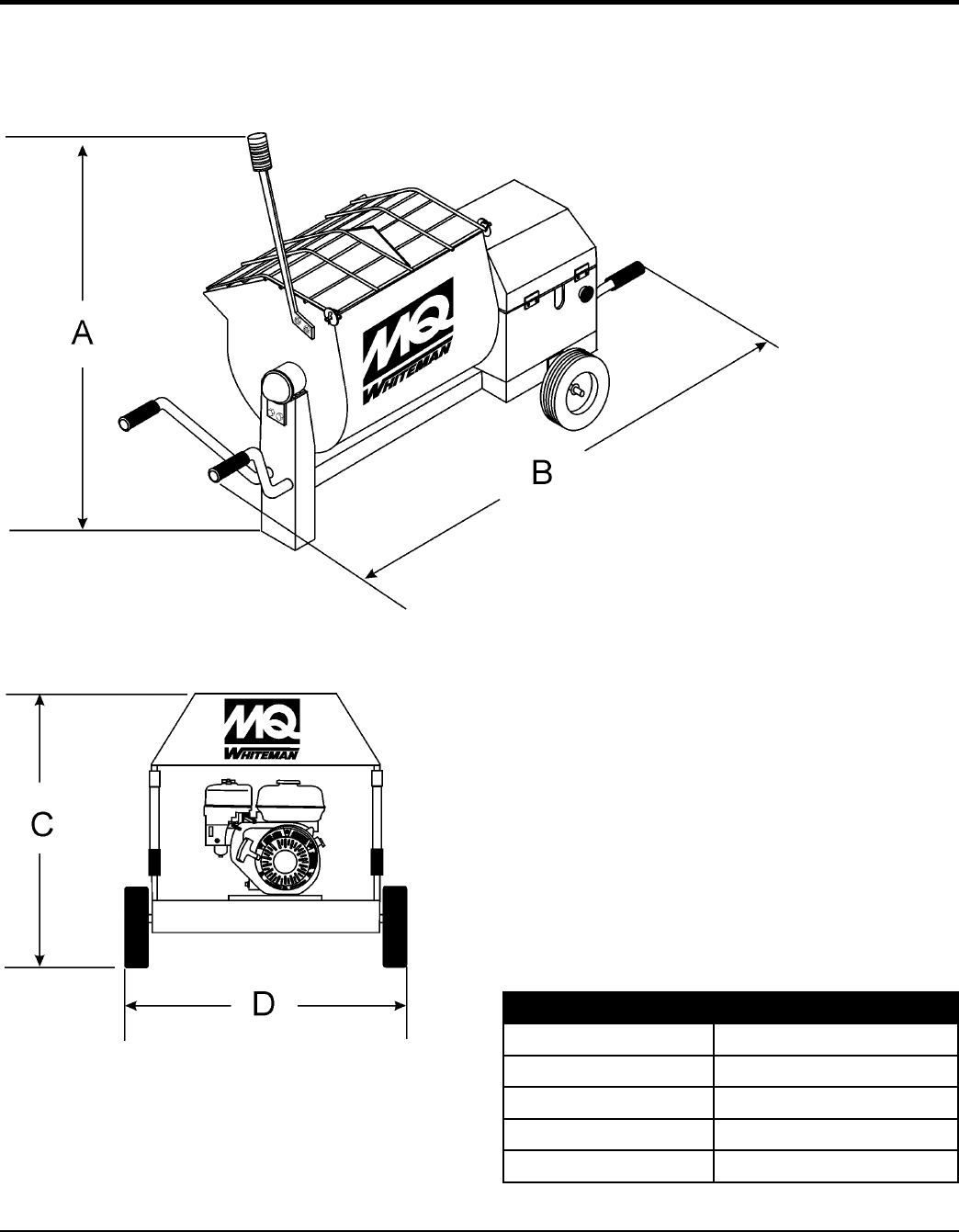
DIMENSIONS
Table 3. Mixer Dimensions
Reference Designator Dimension in. (cm.)
A 67 (170)
B 50 (127)
C 56 (142)
D 56 (142)
Figure 1. Dimensions

PAGE 12 — WM45HCE PLASTER/MORTAR MIXER • OPERATION AND PARTS MANUAL — REV. #0 (02/04/13)
GENERAL INFORMATION
GENERAL
The MQ Model WM45HCE plaster and mortar mixer is
shipped completely assembled and has been factory tested.
The drum batch capacity of this mixers is between 1.5 and
2.5 bags. With proper care it will give continuous service
year after year.
This mixer is powered by a Honda GX160 gasoline engine.
The shaft of the engine is attached to a main gear via a
pinion gear. As the main gear rotates it causes the paddle
shaft to rotate.
Before Starting
Before starting the engine, read the engine owner's manual
and thoroughly understand the safety information.
Check the items listed below:
Oil Levels
Be sure to check the oil levels in the engine and engine
reduction unit before starting the unit (gasoline model only).
Hardware
Check all hardware on the mixer before starting. Periodically
inspect all hardware. Loose hardware can contribute to
early component failure and poor performance. Use the
torque chart below as a general guideline and keep all
hardware tight:
HARDWARE DIA TORQUE (lb./ft.)
5/16"- 18 24
3/8" - 24 37
1/2" - 13 39
1/2" - 13 (Grade 8) 90
Engine Care
For care and operation of the Honda engine, refer to the
maintenance procedures in this manual and the engine
manufacturer’s operating instructions furnished with the
engine. We recommend draining and refilling the engine
crankcase at least every thirty hours of operation. Check
the engine oil level daily.
WM45HCE PLASTER MORTAR MIXER • OPERATION AND PARTS MANUAL — REV. #0 (02/04/13) — PAGE 13
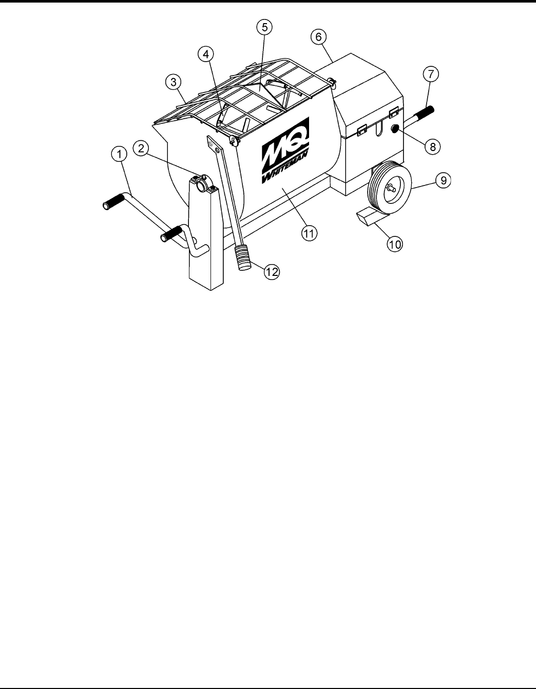
COMPONENTS
Figure 2 illustrates the basic components and controls of
the WM45HCE mixer.
1. Lifting Handle Bars — Use these handle bars to lift
and maneuver the mixer.
2. Pivot Point/Zerk Fitting — There is, on each end of
the mixing drum a zerk grease fitting. These fittings
lubricate the dumping mechanism. Lubricate both
fittings at least twice a week.
3. Safety Grill — Provided for operator safety. This safety
grill is designed to keep hands and solid objects out of
the mixing drum when in use. This grill should be closed
at all times when mixer is in use. DO NOT remove the
grill or grill opening bar. Keep the grill clean by washing
it down daily.
4. Mixing Paddles — Used in the mixing of material.
This unit uses four different types of paddles to provide
a fast uniform mix.
5. Bag Cutter — This feature allows compound mixing
bags to be opened easily, therefore allowing the
contents of the bag to fall directly into the mixing drum.
6. Engine Cover — Lift this cover to gain access to the
engine compartment.
7. Lifting Handle Bars (Engine Side) — Use these
fold-down handle bars to lift and maneuver the mixer.
8. Engine ON/OFF Switch — Pull switch outward to start
engine. Push inward to stop engine.
9. Tires — Replace tires with the recommended type
tire of 12 x 3.
10. Chock Blocks — Place these blocks (not included
as part of the mixer package) under each mixer wheel
to prevent rolling.
11. Steel Mixing Drum — Mixing materials such as mortar,
plaster are to be placed into this drum for mixing.
Always clean the drum after each use
12. Dump Handle — Pull this handle downward to dump
the contents of the drum. Push the handle upward to
return the drum to its vertical position.
Figure 2. Major Components
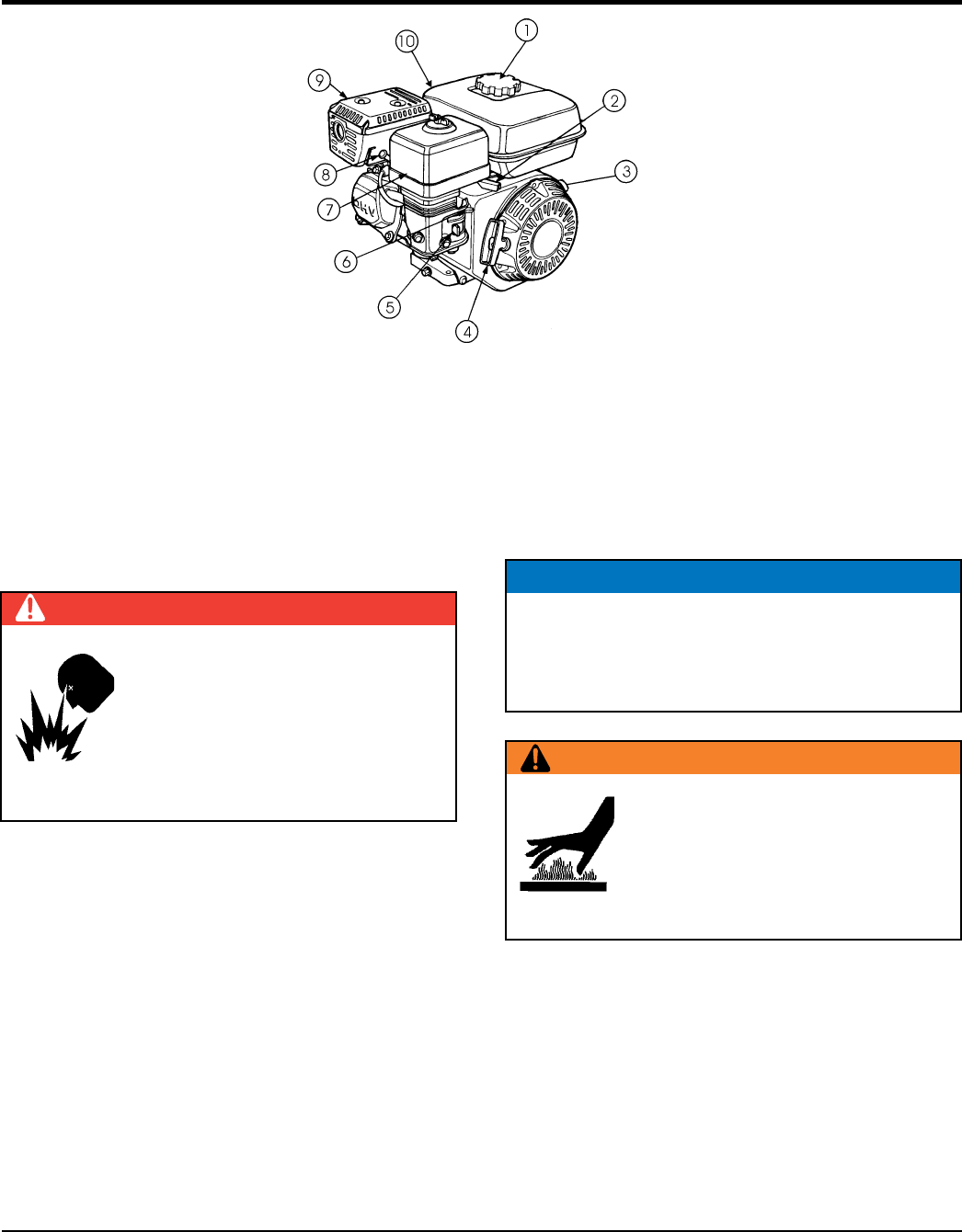
PAGE 14 — WM45HCE PLASTER/MORTAR MIXER • OPERATION AND PARTS MANUAL — REV. #0 (02/04/13)
6. Choke Lever — Used in the starting of a cold engine,
or in cold weather conditions. The choke enriches the
fuel mixture.
7. Air Cleaner — Prevents dirt and other debris from
entering the fuel system. Remove wing-nut on top of
air filter canister to gain access to filter element.
8. Spark Plug — Provides spark to the ignition system.
Set spark plug gap to 0.6 - 0.7 mm (0.028 - 0.031 inch).
Clean spark plug once a week.
9. Muffler — Used to reduce noise and emissions.
10. Fuel Tank — Holds unleaded gasoline. For additional
information refer to engine owner's manual.
NOTICE
Operating the engine without an air filter, with a
damaged air filter, or a filter in need of replacement
will allow dirt to enter the engine, causing rapid engine
wear.
WARNING
Engine components can generate
extreme heat. To prevent burns,
DO NOT touch these areas while the
engine is running or immediately after
operating. NEVER operate the engine
with the muffler removed.
Figure 3. Engine Controls and Components
INITIAL SERVICING
The engine (Figure 3) must be checked for proper
lubrication and filled with fuel prior to operation. Refer to
the manufacturers engine manual for instructions and
details of operation and servicing. Fuel Filler Cap —
Remove this cap to add unleaded gasoline to the fuel tank.
Make sure cap is tightened securely. DO NOT over fill.
1. Fuel Filler Cap — Remove this cap to add unleaded
gasoline to the fuel tank. Make sure cap is tightened
securely. DO NOT over fill.
2. Throttle Lever — Used to adjust engine RPM speed
(lever advanced forward SLOW, lever back toward
operator FAST).
3. Engine ON/OFF Switch — ON position permits engine
starting, OFF position stops engine operations.
4. Recoil Starter (pull rope) — Manual-starting method.
Pull the starter grip until resistance is felt, then pull
briskly and smoothly.
5. Fuel Valve Lever — OPEN to let fuel flow, CLOSE to
stop the flow of fuel.
DANGER
Adding fuel to the tank should be done
only when the engine is stopped and has
had an opportunity to cool down. In the
event of a fuel spill, DO NOT attempt to
start the engine until the fuel residue has
been completely wiped up, and the area
surrounding the engine is dry.
BASIC ENGINE
WM45HCE PLASTER MORTAR MIXER • OPERATION AND PARTS MANUAL — REV. #0 (02/04/13) — PAGE 15
PRE-INSPECTION (ENGINE/MIXER)
BEFORE STARTING
1. Read safety instructions at the
beginning of manual.
2. Clean the mixer, removing dirt and
dust, particularly the engine cooling
air inlet, carburetor and air cleaner.
3. Check the air filter for dirt and dust. If air filter is dirty,
replace air filter with a new one as required.
4. Check carburetor for external dirt and dust. Clean with
dry compressed air.
5. Check fastening nuts and bolts for tightness.
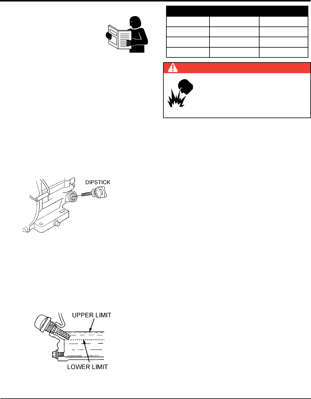
Engine Oil Check
1. To check the engine oil level, place the mixer on secure
level ground with the engine stopped.
2. Remove the filler dipstick from the engine oil filler hole
(Figure 4) and wipe clean.
Figure 4. Engine Oil Dipstick (Removal)
3. Insert and remove the dipstick without screwing it into
the filler neck. Check the oil level shown on the dipstick.
4. If the oil level is low (See Figure 5), fill to the edge of
the oil filler hole with the recommended oil type
(Table 4). Maximum oil capacity is 1.16 quarts
(1.1 liters).
Figure 5. Engine Oil Dipstick (Oil Level)
Table 4. Oil Type
Season Temperature Oil Type
Summer 25°C or Higher SAE 10W-30
Spring/Fall 25°C~10°C SAE 10W-30/20
Winter 0°C or Lower SAE 10W-10
DANGER
Motor fuels are highly flammable and can
be dangerous if mishandled. DO NOT
smoke while refueling. DO NOT attempt
to refuel the mixer if the engine is hot!
or running.
Fuel Check
1. Remove the gasoline cap located on top of fuel tank.
2. Visually inspect to see if the fuel level is low. If fuel is
low, replenish with unleaded fuel.
3. When refueling, be sure to use a strainer for filtration.
DO NOT top-off fuel. Wipe up any spilled fuel
immediately!
Blade Check
Check for worn or defective paddle blades. Make sure that
all blades are adjusted properly. Replace all defective or
damaged blades immediately.
Start/Stop Switch Check
This switch should be tested every time the engine is
started.
Grease Fittings (Dumping Mechanism)
Check the zerk grease fittings at each end of the mixing
drum. These grease fittings lubricate the dumping
mechanism. If the dumping handle is stiff or hard to move
lubricate these fittings.
PAGE 16 — WM45HCE PLASTER/MORTAR MIXER • OPERATION AND PARTS MANUAL — REV. #0 (02/04/13)
INITIAL START-UP (ENGINE)
CAUTION
DO NOT attempt to operate the mixer
until the Safety, General Information and
Inspection sections of this manual have
been read and thoroughly understood.
This section is intended to assist the operator with the
initial start-up of the mixer. It is extremely important that
this section be read carefully before attempting to use the
mixer in the field.
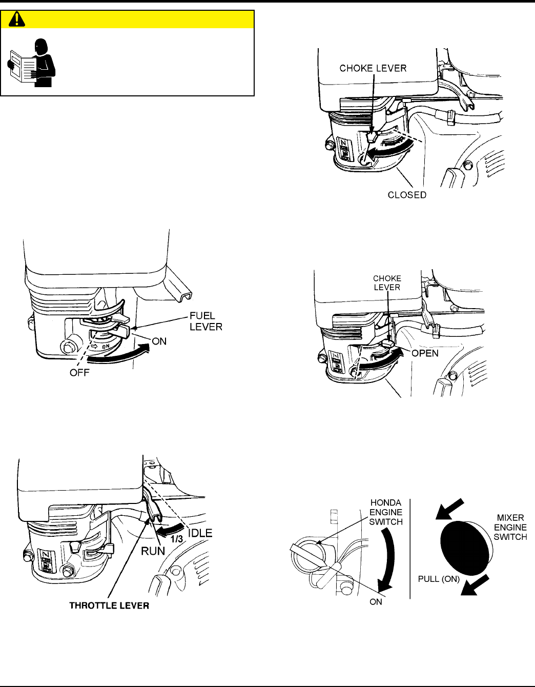
STARTING THE ENGINE (HONDA ENGINE)
1. Place the engine fuel valve lever (Figure 6) to the “ON”
position.
Figure 6. Engine Fuel Valve Lever (ON Position)
2. Move the throttle lever (Figure 7) away from the slow
position, about 1/3 of the way toward the fast
position.
Figure 7. Throttle Lever (1/3 Start Position)
3. Place the choke lever (Figure 8) in the “CLOSED”
position if starting a cold engine.
Figure 8. Engine Choke Lever (Closed)
4. Place the choke lever (Figure 9) in the “OPEN” position
if starting a warm engine or the temperature is warm.
Figure 9. Engine Choke Lever (Open)
5. Place the engine ON/OFF switch (Figure 10) in the
“ON” position.
Figure 10. Engine ON/OFF
Switches (ON Position)
WM45HCE PLASTER MORTAR MIXER • OPERATION AND PARTS MANUAL — REV. #0 (02/04/13) — PAGE 17
INITIAL START-UP (ENGINE)
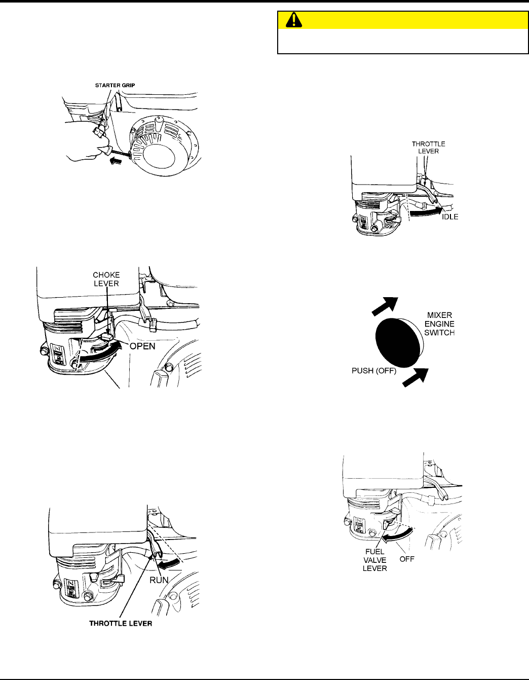
STOPPING THE ENGINE
Normal Shutdown
1. Move the throttle lever to the IDLE position (Figure 14)
and run the engine for three minutes at low speed.
Figure 14. Throttle Lever (Idle)
2. After the engine cools, push the engine ON/OFF switch
inward to the “OFF” position (Figure 15).
Figure 15. Engine ON/OFF Switch (OFF)
3. Place the fuel shut-off lever (Figure 16) in the "OFF"
position.
Figure 16. Fuel Valve Lever (OFF)
Emergency Shutdown
1. Move the throttle lever quickly to the IDLE position, and
place the engine ON/OFF switch in the OFF position.
CAUTION
ALWAYS run engine at full speed while mixing.
6. Grasp the starter grip (Figure 11) and slowly pull it out.
The resistance becomes the hardest at a certain
position, corresponding to the compression point. Pull
the starter grip briskly and smoothly for starting.
Figure 11. Starter Grip
7. If the choke lever was moved to the "CLOSED" position
to start the engine gradually move it to the "OPEN"
position (Figure 12) as the engine warms up. If the
engine has not started repeat steps 1 through 6.
Figure 12. Choke Lever (Open)
8. Before the mixer is placed in to operation, run the
engine for several minutes. Check for fuel leaks, and
noises that would associate with a lose component.
9. To begin mixing, place the throttle lever (Figure 13) in
the “RUN” position.
Figure 13. Throttle Lever (Run)

PAGE 18 — WM45HCE PLASTER/MORTAR MIXER • OPERATION AND PARTS MANUAL — REV. #0 (02/04/13)
ENGINE MAINTENANCE
Perform engine maintenance procedures as referenced by Table 5 below:
Table 5. Engine Maintenance Schedule
Description (3) Operation Before
First
Month or
10 hrs
Every 3
Months or
25 hrs
Every 6
Months or
50 hrs
Every
Year or
100 hrs
Every 2
Years or
200 hrs
Engine Oil CHECK X
CHANGE X
Air Cleaner CHECK X
CHANGE X (1)
All Nuts and
Bolts
Re-tighten If
Necessary X
Spark Plug CHECK-CLEAN X
REPLACE X
Cooling Fins CHECK X
Spark Arrester CLEAN X
Fuel Tank CLEAN X
Fuel Filter CHECK X
Idle Speed CHECK-ADJUST X (2)
Valve Clearance CHECK-ADJUST X (2)
Fuel lines CHECK Every 2 years (replace if necessary) (2)
1. Service more frequently when used in DUSTY areas.
2. These items should be serviced by your service dealer, unless you have the proper tools and are mechanically
proficient. Refer to the HONDA shop Manual for service procedures.
3. For commercial use, log hours of operation to determine proper maintenance intervals.
NOTICE
Reference manufacturer engine manual for specific
servicing instructions.
MAINTENANCE (ENGINE)
WM45HCE PLASTER MORTAR MIXER • OPERATION AND PARTS MANUAL — REV. #0 (02/04/13) — PAGE 19
MAINTENANCE
Perform the engine maintenance procedures as indicated
below:
Daily
1. Thoroughly remove dirt and oil from the engine and
control area. Clean or replace the air cleaner elements
as necessary. Check and retighten all fasteners as
necessary.
Weekly
1. Remove the fuel filter cap and clean the inside of the
fuel tank.
2. Remove or clean the filter at the bottom of the tank.
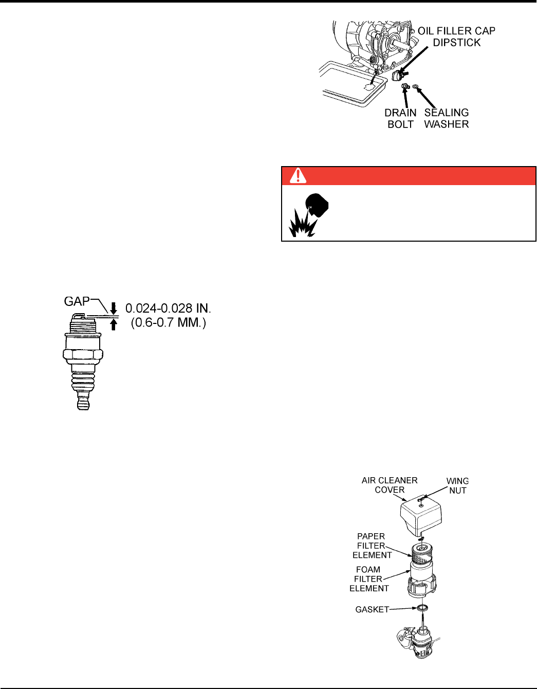
3. Remove and clean the spark plug (Figure 17), then
adjust the spark gap to 0.028~0.031 inch
(0.6~0.7 mm). This unit has electronic ignition, which
requires no adjustments.
ENGINE OIL
1. Drain the engine oil when the oil is warm as shown
in Figure 18.
2. Remove the oil drain bolt and sealing washer and allow
the oil to drain into a suitable container.
3. Install drain bolt with sealing washer and tighten
securely.
4. Replace engine oil with recommended type oil as listed
in Table 4. Engine oil capacity is 1.16 quarts (1.1 liters).
DO NOT over fill.
Figure 17. Spark Plug Gap
MAINTENANCE (ENGINE)
Figure 18. Engine Oil (Draining)
ENGINE AIR CLEANER
1. Remove the air cleaner cover and foam filter element
as shown in Figure 19.
2. Tap the paper filter element (Figure 19) several
times on a hard surface to remove dirt, or
blow compressed air [not exceeding 30 psi (207 kPa,
2.1 kgf/cm2)] through the filter element from the air
cleaner case side. NEVER brush off dirt. Brushing
will force dirt into the fibers. Replace the paper filter
element if it is excessively dirty.
3. Clean foam element in warm, soapy water or
non-flammable solvent. Rinse and dry thoroughly. Dip
the element in clean engine oil and completely squeeze
out the excess oil from the element before installing.
Figure 19. Engine Air Cleaner
DANGER
DO NOT use gasoline as a cleaning
solvent, because that would create a risk
of fire or explosion.
PAGE 20 — WM45HCE PLASTER/MORTAR MIXER • OPERATION AND PARTS MANUAL — REV. #0 (02/04/13)
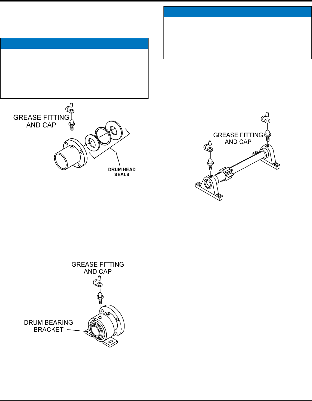
MAINTENANCE (MIXER)
Drum Head Seals
There is 1 set of drum head seals (Figure 20) that will
require lubrication.
Figure 20. Grease Fittings (Drum Head Seals)
Drum Bearing Bracket Lubrication
There is 1 set of drum bearing brackets (Figure 21) that
will require lubrication. These brackets are intended to
make the drum rotate freely. Lubricate the grease fitting for
each drum bearing bracket every month or when the
drum becomes difficult to position using multi-purpose
grade grease.
Figure 21. Grease Fittings
(Dumping Mechanism)
NOTICE
Important- Drum Head Seal Care
Grease seals every 40 hours of operation
using any grade #1 lithium base grease. Apply
grease until visible of mixing tub (over grease).
This will purge seal system of contamination.
Countershaft Bearing Lubrication
There is 1 set of countershaft bearings (Figure 22) that will
require lubrication. Lubricate the grease fitting for each
countershaft bearing every 40 hours of operation using
any grade lithium base grease.
Figure 22. Grease Fittings (Countershaft)
NOTICE
Lubricating Grease Fittings
Failure to lubricate the drum bearing grease fittings
periodically will cause the dumping mechanism
to stiffen, making the mixing drum hard to dump.
WM45HCE PLASTER MORTAR MIXER • OPERATION AND PARTS MANUAL — REV. #0 (02/04/13) — PAGE 21
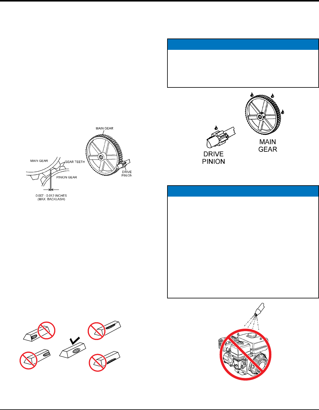
Main Gear and Drive Pinion Alignment
1. Disconnect the spark plug wire. In addition make sure
the clutch engagement lever is dis-engaged to relieve
V-belt tension.
2. The countershaft and drive pinion are mounted on a
slotted base. To align drive pinion with main gear, loosen
the pillow block mounting bolts and move them until
the necessary alignment has been made. Remember
gears must be paralleled aligned not skewed.
3. Using your hand, slightly move (rock) the drive pulley
back and forth to determine the amount of backlash.
Insert feeler gauge between gears to determine
backlash distance. Backlash should range between
0.007- 0.012 inches (Figure 23).
Figure 23. Drive Pinion and
Main Gear (Backlash)
Inspect Tooth Contact Between Main Gear and
Drive Pinion
1. Coat 3 or 4 teeth at 3 different positions on the main
gear with yellow paint.
2. Rotate the drive pulley in both directions.
3. Inspect the tooth pattern.
4. If gear teeth are not contacting properly (Figure 24),
adjust pillow block to correct the problem.
Figure 24. Gear Teeth Alignment
HEAL
CONTACT
TOE
CONTACT
FACE
CONTACT
FLANK
CONTACT
PROPER
CONTACT
MAINTENANCE (MIXER)
Gear Lubrication
The surface of the pinion and main gear (Figure 25) should
be very lightly greased.
Figure 25. Pinion and Bull Gear Lubrication
Figure 26. No Spraying of Water
NOTICE
Re Grease main and pinion gears every 250 hours of
operation. IMPORTANT! avoid over-greasing. Excess
grease will accumulate contaminates and cause
premature wear.
NOTICE
Mixer Cleaning
ALWAYS disconnect the spark plug wire before
cleaning inside of mixing drum.
NEVER pour or spray water (Figure 26) over engine.
For consistent performance, long life and high quality
mixing, thoroughly clean the mixer inside and out at
the end of each day’s operation. To prevent lumps of
dried mortar from forming and contamination of future
batches, do not allow a buildup of materials to form on
the blades or anywhere inside the drum.

PAGE 22 — WM45HCE PLASTER/MORTAR MIXER • OPERATION AND PARTS MANUAL — REV. #0 (02/04/13)
TROUBLESHOOTING (ENGINE)
Practically all breakdowns can be prevented by proper
handling and maintenance inspections, but in the event
of a breakdown, please take remedial action following
the diagnosis based on the Troubleshooting Tables If the
problem cannot be remedied, please leave the unit just as
it is and consult or company's service department.
Troubleshooting (Engine)
Symptom Possible Problem Solution
Diffi cult to start, fuel is available, but no spark at
spark plug.
Spark plug bridging? Check gap, insulation or replace spark plug.
Carbon deposit on spark plug? Clean or replace spark plug.
Short circuit due to defi cient spark plug
insulation? Check spark plug insulation, replace if worn.
Improper spark plug gap? Set to proper gap.
Fuel reaching carburetor? Check fuel line.
Water in fuel tank? Flush or replace fuel tank.
Fuel fi lter clogged? Replace fuel fi lter.
Stuck carburetor? Check fl oat mechanism.
Spark plug is red? Check transistor ignition unit.
Spark plug is bluish white?
If insuffi cient compression, repair or replace
engine. If injected air leaking, correct leak. If
carburetor jets clogged, clean carburetor.
No spark present at tip of spark plug?
Check transistor ignition unit is broken, and
replace defective unit. Check if voltage cord
cracked or broken and replace. Check if spark
plug if fouled and replace.
No oil? Add oil as required.
Oil pressure alarm lamp blinks upon starting? (if
applicable)
Check automatic shutdown circuit, "oil sensor".
(if applicable)
Diffi cult to start, fuel is available, and spark is
present at the spark plug.
ON/OFF switch is shorted? Check switch wiring, replace switch.
Ignition coil defective? Replace ignition coil.
Improper spark gap, points dirty? Set correct spark gap and clean points.
Condenser insulation worn or short circuiting? Replace condenser.
Spark plug wire broken or short circuiting? Replace defective spark plug wiring.
Diffi cult to start, fuel is available, spark is
present and compression is normal.
Wrong fuel type? Flush fuel system, replace with correct type of
fuel.
Water or dust in fuel system? Flush fuel system.
Air cleaner dirty? Clean or replace air cleaner.
Choke open? Close choke.
Diffi cult to start, fuel is available, spark is
present and compression is low.
Suction/exhaust valve stuck or protruded? Reseat valves.
Piston ring and/or cylinder worn? Replace piston rings and/or piston.
Cylinder head and/or spark plug not tightened
properly? Torque cylinder head bolts and spark plug.
Head gasket and/or spark plug gasket damaged? Replace head and spark plug gaskets.
No fuel present at carburetor.
No fuel in fuel tank? Fill with correct type of fuel.
Fuel cock does not open properly? Apply lubricant to loosen fuel cock lever,
replace if necessary.
Fuel fi lter/lines clogged? Replace fuel fi lter.
Fuel tank cap breather hole clogged? Clean or replace fuel tank cap.
Air in fuel line? Bleed fuel line.

WM45HCE PLASTER MORTAR MIXER • OPERATION AND PARTS MANUAL — REV. #0 (02/04/13) — PAGE 23
TROUBLESHOOTING (ENGINE/MIXER)
Troubleshooting (Mixer)
Symptom Possible Problem Solution
Blades will not rotate.
Worn or defective main gear? Check main gear. Replace if worn or
broken.
Worn or defective pinion gear? Check pinion gear. Replace if worn or
broken.
Material load too heavy, exceeding
mixer capability?
Reduce amount of material being
mixed.
Object stuck inside mixing drum,
jamming paddle rotation?
Stop engine. Empty out drum
contents. Remove obstruction.
Improper engine speed? Check and adjust engine speed.
Material leaking from drum ends. Worn or defective paddle shaft seals? Replace seals.
Drum diffi cult to discharge (tilt).
Defective or worn drum support
brackets? Apply grease to bracket or replace.
Blades adjusted too tight. Adjust blades until they almost touch
side walls of drum.

PAGE 24 — WM45HCE PLASTER/MORTAR MIXER • OPERATION AND PARTS MANUAL — REV. #0 (02/04/13)
The following section explains the different symbols and
remarks used in the Parts section of this manual. Use the
help numbers found on the back page of the manual if there
are any questions.
SAMPLE PARTS LIST
NO. PART NO. PART NAME QTY. REMARKS
1 12345 BOLT ......................1 .....INCLUDES ITEMS W/%
2% WASHER, 1/4 IN. ...........NOT SOLD SEPARATELY
2% 12347 WASHER, 3/8 IN. ...1 .....MQ-45T ONLY
3 12348 HOSE ..................A/R ...MAKE LOCALLY
4 12349 BEARING ..............1 .....S/N 2345B AND ABOVE
NO. Column
Unique Symbols — All items with same unique
symbol
(@, #, +, %, or >) in the number column belong to the
same assembly or kit, which is indicated by a note in the
“Remarks” column.
Duplicate Item Numbers — Duplicate numbers indicate
multiple part numbers, which are in effect for the same
general item, such as different size saw blade guards in
use or a part that has been updated on newer versions
of the same machine.
PART NO. Column
Numbers Used — Part numbers can be indicated by a
number, a blank entry, or TBD.
TBD (To Be Determined) is generally used to show a
part that has not been assigned a formal part number
at the time of publication.
A blank entry generally indicates that the item is not sold
separately or is not sold by Multiquip. Other entries will
be clarified in the “Remarks” Column.
NOTICE
The contents and part numbers listed in the parts
section are subject to change without notice. Multiquip
does not guarantee the availability of the parts listed.
NOTICE
When ordering a part that has more than one item
number listed, check the remarks column for help in
determining the proper part to order.
QTY. Column
Numbers Used
— Item quantity can be indicated by a
number, a blank entry, or A/R.
A/R (As Required) is generally used for hoses or other
parts that are sold in bulk and cut to length.
A blank entry generally indicates that the item is not sold
separately. Other entries will be clarified in the “Remarks”
Column.
REMARKS Column
Some of the most common notes found in the “Remarks”
Column are listed below. Other additional notes needed
to describe the item can also be shown.
Assembly/Kit — All items on the parts list with the
same unique symbol will be included when this item is
purchased.
Indicated by:
“INCLUDES ITEMS W/(unique symbol)”
Serial Number Break
— Used to list an effective serial
number range where a particular part is used.
Indicated by:
“S/N XXXXX AND BELOW”
“S/N XXXX AND ABOVE”
“S/N XXXX TO S/N XXX”
Specific Model Number Use
— Indicates that the part
is used only with the specific model number or model
number variant listed. It can also be used to show a
part is NOT used on a specific model or model number
variant.
Indicated by:
“XXXXX ONLY”
“NOT USED ON XXXX”
“Make/Obtain Locally” — Indicates that the part can
be purchased at any hardware shop or made out of
available items. Examples include battery cables, shims,
and certain washers and nuts.
“Not Sold Separately”
— Indicates that an item cannot
be purchased as a separate item and is either part of an
assembly/kit that can be purchased, or is not available
for sale through Multiquip.
EXPLANATION OF CODE IN REMARKS COLUMN

WM45HCE PLASTER MORTAR MIXER • OPERATION AND PARTS MANUAL — REV. #0 (02/04/13) — PAGE 25
SUGGESTED SPARE PARTS
WM45HCE PLASTER/MORTAR MIXER WITH HONDA GX160UT1HX2 ENGINE
1 to 3 units
Qty. P/N Description
2............491010 .................. RUBBER LATCH ASSY.
1............8000-008 .............. KIT, RUBBER BLADES
3............9807956846 .......... SPARK PLUG HONDA
3............17210ZE1822 ....... ELEMENT, AIR HONDA
1............28462ZH8003 ....... ROPE, RECOIL STARTER, HONDA
NOTICE
Part numbers on this Suggested Spare Parts list may
supersede/replace the part numbers shown in the
following parts lists.
PAGE 26 — WM45HCE PLASTER/MORTAR MIXER • OPERATION AND PARTS MANUAL — REV. #0 (02/04/13)
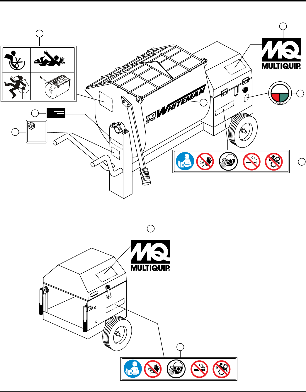
NAMEPLATE AND DECALS
2
3
4
L
105
dB
P/N 520916
WA
2
1
P/N 521304
6
5
5
MODEL
SERIAL NO.
7
P/N 521306
P/N 521306

WM45HCE PLASTER MORTAR MIXER • OPERATION AND PARTS MANUAL — REV. #0 (02/04/13) — PAGE 27
NAMEPLATE AND DECALS
NO. PART NO. PART NAME QTY. REMARKS
1 521304 DECAL: MIXING TUB ICONS (4) 1
2 512910 DECAL: MQ LOGO 2
3 521305 DECAL: PUSH TO STOP 1
4 504714 DECAL: MQ/WHITEMAN LOGO 1
5 521306 DECAL: SAFETY ICONS (5) 2
6 520916 DECAL: NOISE LEVEL 1
7 DECAL: SERIAL PLATE .......................... 1 .................. CONTACT MQ PARTS DEPT.
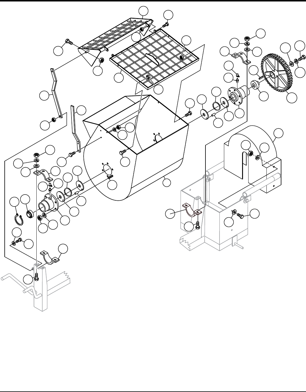
PAGE 28 — WM45HCE PLASTER/MORTAR MIXER • OPERATION AND PARTS MANUAL — REV. #0 (02/04/13)
STEEL TUB ASSY.
37
77
42
48
42
20
80
81
2
39
73
74
69
70
71
22
66
79
3
64 65
65
65
67 67
67
63
63
21
21
18
43
62
25
43
26
40
76
69
37
77
78
42
48
25
43
18
20
19
62
19
56
70
27
24
26
40
82 84
83
85
REAR
FRONT
PART OF
FRAME
PART OF
FRAME

WM45HCE PLASTER MORTAR MIXER • OPERATION AND PARTS MANUAL — REV. #0 (02/04/13) — PAGE 29
STEEL TUB ASSY.
NO. PART NO. PART NAME QTY. REMARKS
2# 26084-352 DRUM 1
3 26085-351 GRATE, FIXED 1
12 23180-001 HAND GRIP 1
18# 19728-001 TRUNNION 2
19+# 19722-001 SHAFT SEAL 2
20# 33177-001 SEALED BEARING 2
21+# 33044-001 SHAFT SEAL 2
22 25492-001 DUMP LEVER 1
24# 33048-001 MAIN GEAR 1
25 33084-001 BEARING HALF - UPPER 2
26 33084-002 BEARING HALF - LOWER 2
27# 18937-001 LARGE WASHER 1
37# 07745-001 GREASE FITTING 4
39# 17985-008 BOLT 3/8 X 1-1/4" 8
40 17985-010 CARRIAGE BOLT 3/8 - 16 X 1-1/4 4
42# 07029-006 LOCKWASHER 3/8 16
43# 07033-006 HEX NUT 3/8 - 16 14
48 07030-006 FLATWASHER 3/8 4
56# 06501-008 HEX HEAD CAP SCREW 3/8 - 16 X 1 1
62# 07594-012 ROLL PIN 3/16 X 3/4 2
63# 19721-001 RETAINING RING 2
64 801154 GRATE, MOBILE 1
65 EM963610 CAPSCREW 3/8"NCx1-1/4" G8 6
66 492581 NUT 1/4"-20 NYLON 1
67 EM969013 NUT NYLOK 6
69 EM963692 CAPSCREW 1/2-13x1-1/2 HHCS 3
70 6109180 WASHER LOCK 1/2" 3
71 6109160 HEX NUT 1/2-13 2
73 801170 LIFT BAR 1
74 492584 NUT LOCK 1/2" 1
76 6109170 WASHER-1/2" FLAT 1
77 491008 FITTING PROTECTOR 2
78 500214 KEY SQUARE 1/4x1/4x1-1/2 1
79 492357 BOLT, GR 8 1
80 513642 SNAP RING 1
81 801166 GEAR GUARD 1
82 2101428 NUT, HEX 1/4-20 4
83 492356 BOLT, 1/4 X 3/4 4
84 2101402 WASHER, LOCK 1/4 4
85 EM923057 WASHER, FLAT 1/4 4
25648-501 SHAFT SEAL KIT ..............................................1................INCLUDES ITEMS W/+
26083-502 DRUM ASSY. W/SHAFT MAIN GEAR ...............1................INCLUDES ITEM W/#, ALSO
.............................................................................................INCLUDES PADDLE SHAFT
.............................................................................................P/N 29062-351
PAGE 30 — WM45HCE PLASTER/MORTAR MIXER • OPERATION AND PARTS MANUAL — REV. #0 (02/04/13)
PADDLE SHAFT ASSY.

WM45HCE PLASTER MORTAR MIXER • OPERATION AND PARTS MANUAL — REV. #0 (02/04/13) — PAGE 31
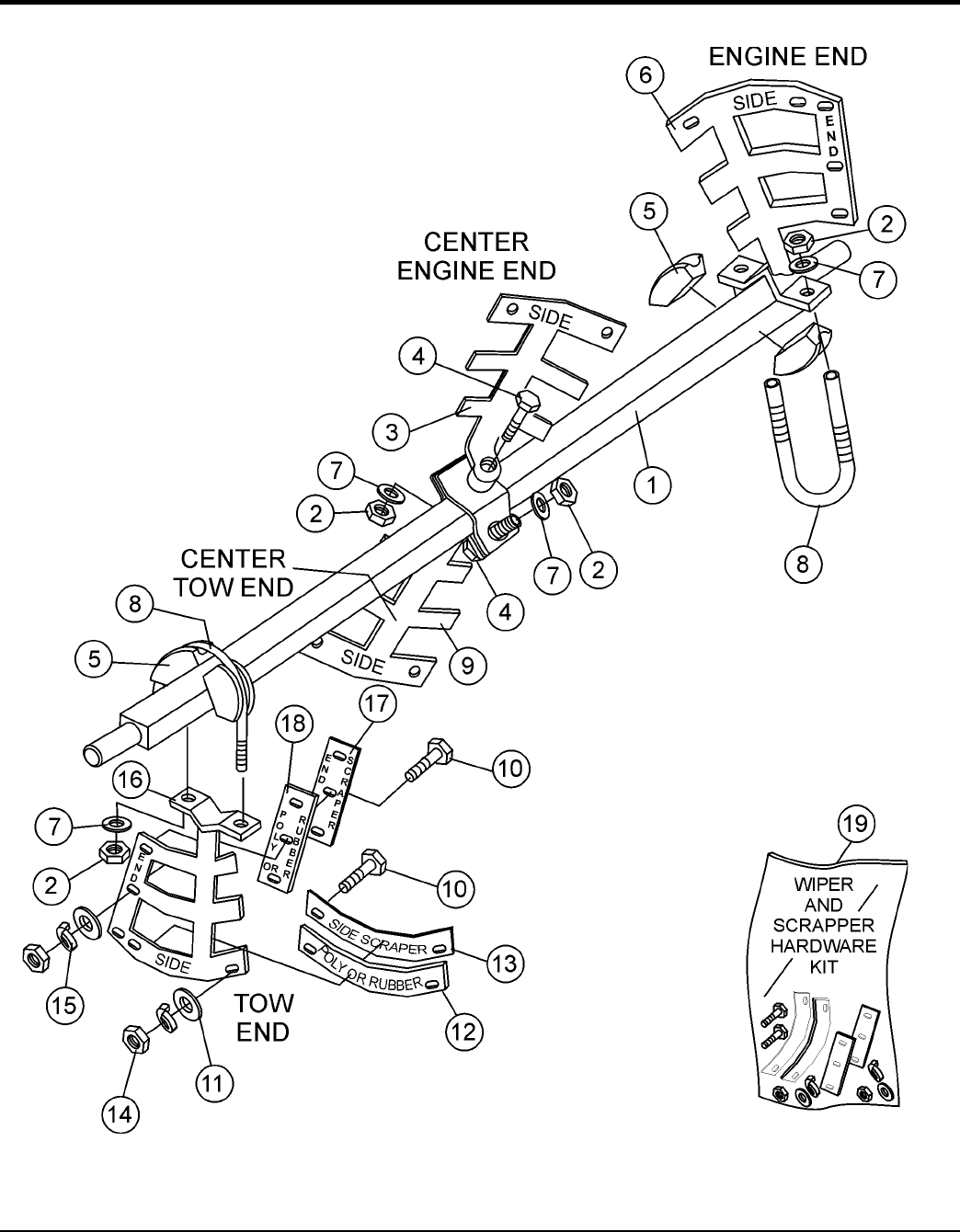
PADDLE SHAFT ASSY.
NO. PART NO. PART NAME QTY. REMARKS
1 29062-351 PADDLE SHAFT 1
2 492584 NUT, LOCK 1/2" 6
3 530181C PADDLE ARM, CENTER ENGINE END 1
4 492400 SCREW, HHC 1/2"-13 X 3-1/2 2
5 EM200292 INSERT, PADDLE ARM 4
6 530180C PADDLE ARM, ENGINE END 1
7 504322 WASHER, FLAT 1/2" 6
8 EM200297 U-BOLT, END PADDLES 2
9 530179C PADDLE ARM, CENTER TOW END 1
10# 505196 SCREW, HHC 5/16-18 X 1-3/4 G5 12
11# 3019092 WASHER, FLAT 3/8" 12
12# 514725 BLADE, SIDE, RUBBER 4
13# 514726 BLADE, SIDE, SCRAPPER 4
14# 1456 NUT, HEX FINISH 3/8-16" NC G5 12
15# 0166A WASHER, LOCK 3.8" 12
16 530182C PADDLE ARM, TOW END 1
17# 530201 BLADE ,SCRAPPER END 2
18# 33017-001 BLADE, RUBBER END 2
19 80000-008 KIT, RUBBER BLADE SCRAPPER & HARDWARE .....1 ................. INCLUDES ITEMS W/#
PAGE 32 — WM45HCE PLASTER/MORTAR MIXER • OPERATION AND PARTS MANUAL — REV. #0 (02/04/13)
FRAME ASSY.

WM45HCE PLASTER MORTAR MIXER • OPERATION AND PARTS MANUAL — REV. #0 (02/04/13) — PAGE 33
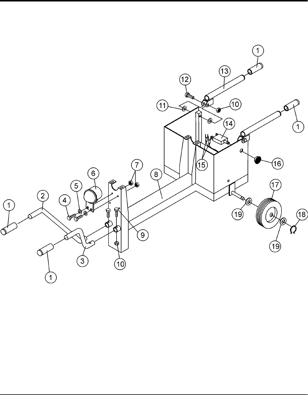
FRAME ASSY.
NO. PART NO. PART NAME QTY. REMARKS
1 EM98195 GRIP, RUBBER BLACK 4
2 530467 HANDLE, FRONT-LEFT 1
3 530226 HANDLE, FRONT-RIGHT 1
4 492294 BOLT, HEX 1/4" NC X 3/4" G2 2
5 2101402 WASHER, LOCK 1/4" 2
6 517684 DUST CAP 1
7 492581 NUT, 1/4-20 NYLOCK 2
8 530168 FRAME 1
9 492381 SCREW, 3/8 NC 2-1/2 G5 2
10 EM969013 NUT, NYLOCK 3/8" ............................................4................REPLACES P/N 492583
11 3019092 WASHER, FLAT 3/8" ..........................................4................REPLACES P/N 492598
12 EM217 BOLT, 3/8-16 X 2-1/2 HEX HD. GR 5 .................2................REPLACES P/N 492381
13 518062 HANDLE FOLDING 2
14 29173-001 SWITCH, PUSH-PULL W/O KNOB 1
15 504135C WIRE HARNESS 1
16 29174-001 KNOB MUSHROOM 1
17 491002 WHEEL , TIRE ASSY. 2
18 490957 SNAP RING 5100-100 2
19 501299 WASHER, FLAT 4
PAGE 34 — WM45HCE PLASTER/MORTAR MIXER • OPERATION AND PARTS MANUAL — REV. #0 (02/04/13)
ENGINE COVER ASSY.

WM45HCE PLASTER MORTAR MIXER • OPERATION AND PARTS MANUAL — REV. #0 (02/04/13) — PAGE 35
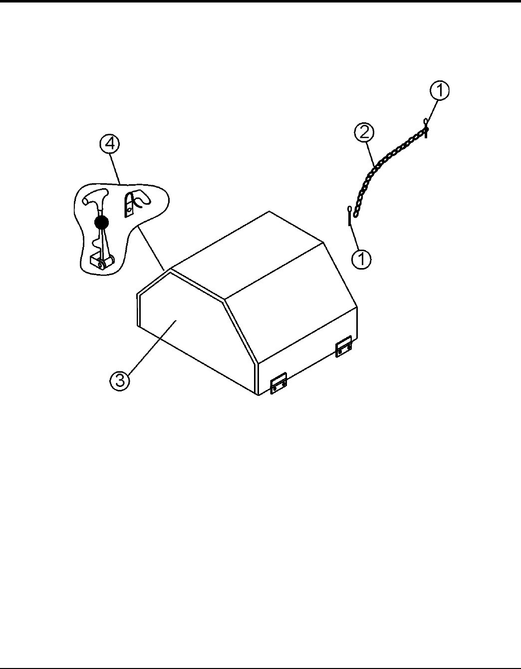
ENGINE COVER ASSY.
NO. PART NO. PART NAME QTY. REMARKS
1 07028-057 COTTER PIN 5/32 x 1/2 2
2 18604-005 RETAINER CHAIN 1
3 26922-351 ENGINE HOUSE ASSY. 1
4 491010 LATCH ASSY. 1
PAGE 36 — WM45HCE PLASTER/MORTAR MIXER • OPERATION AND PARTS MANUAL — REV. #0 (02/04/13)
ENGINE/GUARD ASSY.

WM45HCE PLASTER MORTAR MIXER • OPERATION AND PARTS MANUAL — REV. #0 (02/04/13) — PAGE 37
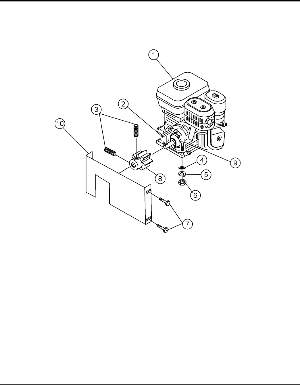
ENGINE/GUARD ASSY.
NO. PART NO. PART NAME QTY. REMARKS
1 ENGINE-5.5 H.P. HONDA, GX160UT1HX 1
2 10057-016 SQUARE KEY 3/16 x 1-1/2 1
3 18941-004 SOCKET SET SCREW 1/4-20 x1/4 2
4 07030-005 FLATWASHER 5/16 4
5 07029-005 LOCKWASHER 5/16 4
6 07033-005 HEX NUT 5/16 -18 4
7 06499-006 CAP SCREW 1/4-20 x 3/4 4
8 33054-001 PINION GEAR 1
9 06500-012 CAP SCREW 5/16 - 18 x 1-1/2 4
10 530170 GEAR GUARD 1

PAGE 38 — WM45HCE PLASTER/MORTAR MIXER • OPERATION AND PARTS MANUAL — REV. #0 (02/04/13)
TERMS AND CONDITIONS OF SALE — PARTS
PAYMENT TERMS
Terms of payment for parts are net 30 days.
FREIGHT POLICY
All parts orders will be shipped collect or
prepaid with the charges added to the invoice.
All shipments are F.O.B. point of origin.
Multiquip’s responsibility ceases when a
signed manifest has been obtained from the
carrier, and any claim for shortage or damage
must be settled between the consignee and
the carrier.
MINIMUM ORDER
The minimum charge for orders from Multiquip
is $15.00 net. Customers will be asked for
instructions regarding handling of orders not
meeting this requirement.
RETURNED GOODS POLICY
Return shipments will be accepted and
credit will be allowed, subject to the following
provisions:
1. A Returned Material Authorization
must be approved by Multiquip prior to
shipment.
2. To obtain a Return Material Authorization,
a list must be provided to Multiquip
Parts Sales that defi nes item numbers,
quantities, and descriptions of the items
to be returned.
a. The parts numbers and descriptions
must match the current parts price
list.
b. The list must be typed or computer
generated.
c. The list must state the reason(s)
for the return.
d. The list must reference the sales
order(s ) or i nvoi ce (s) under
which the items were originally
purchased.
e. The list must include the name
and phone number of the person
requesting the RMA.
3. A copy of the Return Material Authorization
must accompany the return shipment.
4. Freight is at the sender’s expense. All
parts must be returned freight prepaid to
Multiquip’s designated receiving point.
5. Parts must be in new and resalable
condition, in the original Multiquip
package (if any), and with Multiquip part
numbers clearly marked.
6. The following items are not returnable:
a. Obsolete parts. (If an item is in the
price book and shows as being
replaced by another item, it is
obsolete.)
b. Any parts with a limited shelf life
(such as gaskets, seals, “O” rings,
and other rubber parts) that were
purchased more than six months
prior to the return date.
c. Any line item with an extended
dealer net price of less than
$5.00.
d. Special order items.
e. Electrical components.
f. Paint, chemicals, and lubricants.
g. Decals and paper products.
h. Items purchased in kits.
7. The sender will be notifi ed of any material
received that is not acceptable.
8. Such material will be held for five
working days from notifi cation, pending
instructions. If a reply is not received
within five days, the material will be
returned to the sender at his expense.
9. Credit on returned parts will be issued
at dealer net price at time of the original
purchase, less a 15% restocking
charge.
10. In cases where an item is accepted, for
which the original purchase document
can not be determined, the price will be
based on the list price that was effective
twelve months prior to the RMA date.
11. Credit issued will be applied to future
purchases only.
PRICING AND REBATES
Prices are subject to change without prior
notice. Price changes are effective on a
specifi c date and all orders received on or
after that date will be billed at the revised price.
Rebates for price declines and added charges
for price increases will not be made for stock
on hand at the time of any price change.
Multiquip reserves the right to quote and
sell direct to Government agencies, and to
Original Equipment Manufacturer accounts
who use our products as integral parts of their
own products.
SPECIAL EXPEDITING SERVICE
A $35.00 surcharge will be added to the
invoice for special handling including bus
shipments, insured parcel post or in cases
where Multiquip must personally deliver the
parts to the carrier.
LIMITATIONS OF SELLER’S LIABILITY
Multiquip shall not be liable hereunder for
damages in excess of the purchase price of
the item with respect to which damages are
claimed, and in no event shall Multiquip be
liable for loss of profi t or good will or for any
other special, consequential or incidental
damages.
LIMITATION OF WARRANTIES
No warranties, express or implied, are
made in connection with the sale of parts or
trade accessories nor as to any engine not
manufactured by Multiquip. Such warranties
made in connection with the sale of new,
complete units are made exclusively by a
statement of warranty packaged with such
units, and Multiquip neither assumes nor
authorizes any person to assume for it
any other obligation or liability whatever in
connection with the sale of its products. Apart
from such written statement of warranty,
there are no warranties, express, implied or
statutory, which extend beyond the description
of the products on the face hereof.
Effective: February 22, 2006

WM45HCE PLASTER MORTAR MIXER • OPERATION AND PARTS MANUAL — REV. #0 (02/04/13) — PAGE 39
NOTES

OPERATION AND PARTS MANUAL
Your Local Dealer is:
HERE’S HOW TO GET HELP
PLEASE HAVE THE MODEL AND SERIAL
NUMBER ON-HAND WHEN CALLING
United StateS
Multiquip Corporate Office MQ Parts Department
18910 Wilmington Ave.
Carson, CA 90746
Contact: mq@multiquip.com
Tel. (800) 421-1244
Fax (310) 537-3927
800-427-1244
310-537-3700
Fax: 800-672-7877
Fax: 310-637-3284
Service Department Warranty Department
800-421-1244
310-537-3700
Fax: 310-537-4259 800-421-1244
310-537-3700
Fax: 310-943-2249
Technical Assistance
800-478-1244 Fax: 310-943-2238
mexico United Kingdom
MQ Cipsa Multiquip (UK) Limited Head Office
Carr. Fed. Mexico-Puebla KM 126.5
Momoxpan, Cholula, Puebla 72760 Mexico
Contact: pmastretta@cipsa.com.mx
Tel: (52) 222-225-9900
Fax: (52) 222-285-0420
Unit 2, Northpoint Industrial Estate,
Globe Lane,
Dukinfield, Cheshire SK16 4UJ
Contact: sales@multiquip.co.uk
Tel: 0161 339 2223
Fax: 0161 339 3226
Canada
Multiquip
4110 Industriel Boul.
Laval, Quebec, Canada H7L 6V3
Contact: jmartin@multiquip.com
Tel: (450) 625-2244
Tel: (877) 963-4411
Fax: (450) 625-8664
© COPYRIGHT 2013, MULTIQUIP INC.
Multiquip Inc
, the MQ logo and the Whiteman logo are registered trademarks of Multiquip Inc. and may not be used, reproduced, or altered without written permission. All other
trademarks are the property of their respective owners and used with permission.
This manual
MUST accompany the equipment at all times. This manual is considered a permanent part of the equipment and should remain with the unit if resold.
The information and specifications included in this publication were in effect at the time of approval for printing. Illustrations, descriptions, references and technical data contained in
this manual are for guidance only and may not be considered as binding. Multiquip Inc. reserves the right to discontinue or change specifications, design or the information published
in this publication at any time without notice and without incurring any obligations.
