Multitone Electronics PLC 2WREP EkoTek Repeater - 2 way radio repeater & beacon User Manual See relevant part
Multitone Electronics PLC EkoTek Repeater - 2 way radio repeater & beacon See relevant part
See relevant part

EkoTek System Installation and Configuration
Manual
Survey
Installation
Configuration
Maintenance
Part No. 9261-8173 Issue 2

EkoTek System Installation and Configuration Manual
Table of Contents
Approvals................................................................................................................................... 1
Compliance ............................................................................................................................ 1
FCC & Industry Canada Statement of Compliance............................................................... 1
WEEE Directive & Product Disposal...................................................................................... 1
System Overview....................................................................................................................... 2
EkoTek Principles .................................................................................................................. 3
Location Reporting................................................................................................................. 4
Beacons.............................................................................................................................. 5
Two-Way Acknowledgement.............................................................................................. 5
Two-Way Radio.................................................................................................................. 5
Frequency Hopping............................................................................................................ 5
Components........................................................................................................................... 6
Single Hub.......................................................................................................................... 6
Repeater............................................................................................................................. 6
2-Way Pager....................................................................................................................... 7
Call Fob .............................................................................................................................. 8
Configuration.......................................................................................................................... 8
Network Parameters........................................................................................................... 8
Diagnostics and Statistics...................................................................................................... 8
Network Design and Survey...................................................................................................... 9
The survey unit..................................................................................................................... 11
The survey unit..................................................................................................................... 11
How to Survey...................................................................................................................... 12
Installation ............................................................................................................................... 14
Pre-requisites....................................................................................................................... 14
Installing the Hub ................................................................................................................. 15
Repeaters............................................................................................................................. 16
PPP Modem......................................................................................................................... 17
Using Windows Hyper Terminal to Set Interface Speed.................................................. 18
The Browser Interface.......................................................................................................... 23
Accessing the HUB with the browser interface.................................................................... 23
Connect the Hub to the PC using Windows XP................................................................... 23
Using the Web Browser to Access the EkoTek Hub............................................................ 25
Main menus.......................................................................................................................... 26
Day/Night.......................................................................................................................... 26
Event Log ......................................................................................................................... 26
Page Device ..................................................................................................................... 27
Part No. 9261-8173 Issue 2 Page i
© 2007 Multitone Electronics PLC

Table of Contents
Pager Log......................................................................................................................... 27
Location............................................................................................................................ 27
Maintenance Menus............................................................................................................. 29
Device Status ................................................................................................................... 29
Device Status Hub............................................................................................................ 29
Device Status Repeaters.................................................................................................. 30
Configuration menus............................................................................................................ 32
Password.......................................................................................................................... 32
System Settings ............................................................................................................... 33
Radio Settings.................................................................................................................. 34
Devices............................................................................................................................. 36
Device Mode..................................................................................................................... 38
Pager groups.................................................................................................................... 42
Alert rules ......................................................................................................................... 43
Factory reset..................................................................................................................... 45
Delete all devices ............................................................................................................. 45
Passwords........................................................................................................................ 46
Archive.............................................................................................................................. 46
Final Checks............................................................................................................................ 48
Appendices.............................................................................................................................. 49
Appendix 1: Miscellaneous system messages .................................................................... 49
Personal security messages ............................................................................................ 49
Pager response messages............................................................................................... 49
Maintenance messages ................................................................................................... 49
Appendix 2 Specifications.................................................................................................... 50
Specifications ................................................................................................................... 50
Appendix 3 RS232 Cable Pin outs for connecting Modem to the Hub................................ 51
Related Documentation and Revision History......................................................................... 52
Revision History ................................................................................................................... 52
Related Documentation ....................................................................................................... 52
9261-8173 Issue 2 Page ii
© 2007 Multitone Electronics PLC

Table of Contents
Figures
Figure 1 EkoTek Personal Security System.............................................................................. 2
Figure 2. Self-Organising Radio Network................................................................................. 3
Figure 3. Node Fail Re-Routing................................................................................................ 3
Figure 4. Typical Network Layout............................................................................................. 4
Figure 5. Location Reporting .................................................................................................... 4
Figure 6. Hub.......................................................................................................................... 15
Figure 7. Hub Back Plate......................................................................................................... 15
Figure 8. Interface Connections .............................................................................................. 16
Figure 9. Repeater.................................................................................................................. 16
Figure 10. Repeater Back Plate ............................................................................................. 17
Figure 11. Hub Interfaces........................................................................................................ 23
9261-8173 Issue 2 Page iii
© 2007 Multitone Electronics PLC

EkoTek System Installation and Configuration Manual
Approvals
Compliance
This product complies with the requirements of the EU Radio & Telecommunications
Terminal Equipment Directive 99/5/EC.
FCC & Industry Canada Statement of Compliance
This device complies with Part 15 of the FCC Rules and Industry Canada Standard RSS
210.
Operation is subject to the following two conditions: (1) this device may not cause harmful
interference and (2) this device must accept any interference that may cause undesired
operation.
Unauthorised modification to this equipment will void the user's authority to continue to
operate the device within the scope of the Industry Canada and FCC Part 15 Rules.
A full technical specification for this product may be obtained from your Multitone
representative.
WEEE Directive & Product Disposal
At the end of its serviceable life, this product should not be treated as
household or general waste. It should be handed over to the applicable
collection point for the recycling of electrical and electronic equipment, or
returned to the supplier for disposal.
9261-8177 Issue 2
© 2007 Multitone Electronics PLC
EkoTek System Installation and Configuration Manual
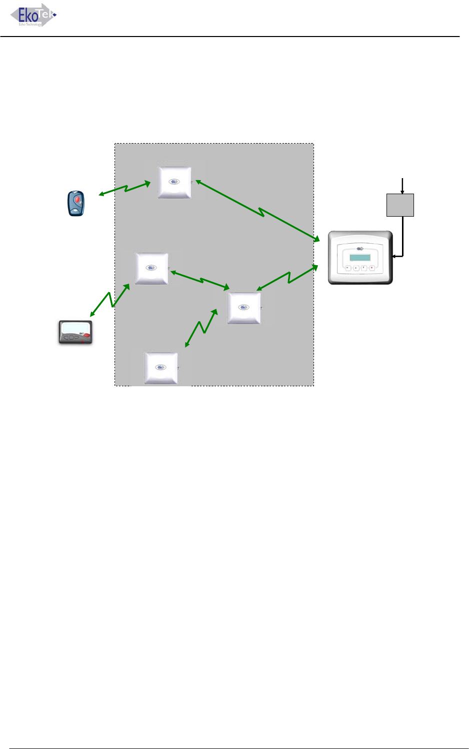
System Overview
EkoTek’s personal security system consists of mobile devices that send assistance
messages to other fixed or mobile devices, where the assistance message and location of
the caller are displayed.
Includes Personal
Security Alarm
Hub
Including Web Server
Repeater
Wireless Link
Call Fob
Pager
Repeater to Repeater
Distance Typically 10 to 15m
Repeater
Repeater
Repeater
Battery Powered
Power
Adaptor
AC
Figure 1 EkoTek Personal Security System
Messages are communicated via a backbone radio network, which makes use of
Repeaters to relay messages around the network.
Due to the multi-hop nature of the backbone network, the physical shape and size of the
network is defined by the layout of the Repeaters, which may be in 3 dimensions e.g.
covering multiple floors in a building.
EkoTek is truly wireless (only the Hub needs AC power), making installation and
expansion very quick and easy.
9261-8173 Issue 2 Page 2
© 2007 Multitone Electronics PLC
EkoTek System Installation and Configuration Manual Overview
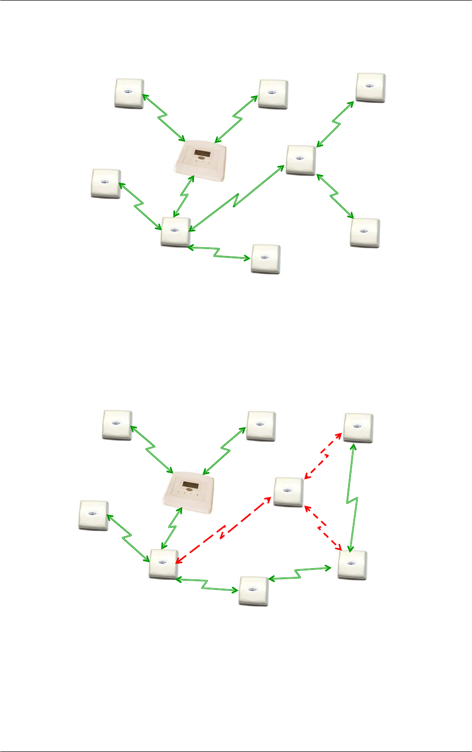
EkoTek Principles
Each EkoTek product is a node, that forms part of a self-organising radio mesh network.
Node Node Node
Node
Node Node
Node
Node
Node
Figure 2. Self-Organising Radio Network
Each node in the network searches for links to nearby nodes, to form the network mesh.
Organising the network is an automatic function carried out by the nodes themselves –
configuration is not required.
As the network is self-organising, it is also self-repairing. Should a node (Repeater) fail,
the network will automatically re-configure around the failed node.
8
Node Node Node
Node
Node
Node
Node
Node
Node
Re-route
Re-route
Figure 3. Node Fail Re-Routing
The dimensions of the network are defined by the layout and distribution of repeater
nodes, the layout being arranged to meet the requirement e.g. reception and public areas
of a hospital, accident and emergency department, or all floors of a building for security
guard lone-worker protection.
9261-8173 Issue 2 Page 3
© 2007 Multitone Electronics PLC
EkoTek System Installation and Configuration Manual Overview
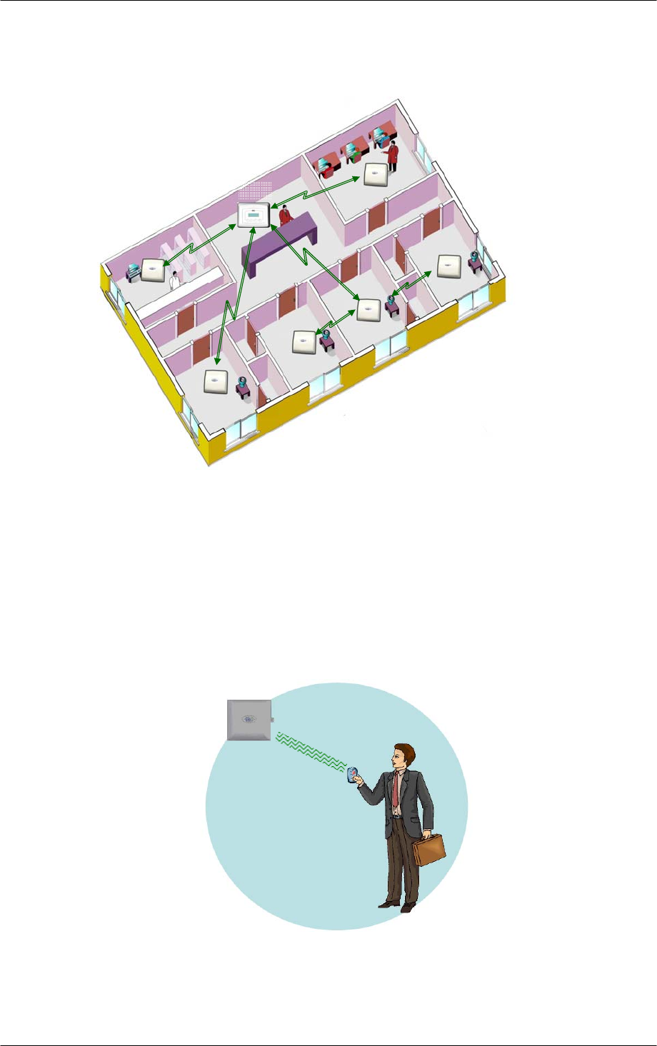
Sizeable networks can be easily built, due to the large number of Repeaters supported by
EkoTek.
Repeaters are normally installed on walls and/or ceilings. The Hub is installed either on a
wall or on a desk, so that the display can be easily seen.
Hub Repeater
Hub and Repeaters automatically
form a mesh network
Figure 4. Typical Network Layout
Location Reporting
When a user raises an alarm signal, it is important to know the location of the user to
ensure that assistance arrives as quickly as possible.
EkoTek provides accurate location reporting, based on location signals sent out by the
Repeaters.
Repeater
Call Fob
Location
Signal
Figure 5. Location Reporting
9261-8173 Issue 2 Page 4
© 2007 Multitone Electronics PLC

EkoTek System Installation and Configuration Manual Overview
When a user signals an alarm, the user identification (name), location and alarm type are
included in the alarm message displayed on the Hub and sent to Pagers.
Beacons
Beacon signals are used to update a device with information of whom its parent is. A
Repeater/Pager/Fob can only ever have one parent at a time. Every 1000ms the
Repeater transmits to the Pager/Fob, which is then updated with its location and will
continue to receive subsequent beacons from the Repeater (its parent). It will be shown
as ‘= [location name]’ on the Pager's display. As the User moves from one Repeater
towards another, they will receive a handover beacon from the Repeater being
approached. The Pager then displays ‘- [location name]’. The Pager/Fob then picks up
location information from the new Repeater and updates itself with the new location.
Two-Way Acknowledgement
For peace of mind of the User, the acceptance of an alarm at the Hub or a two-way Pager
by someone who will be going to the aid of the User, is signalled back to the User by the
Call Fob lamp and beeper changing their alert patterns.
Two-Way Radio
All EkoTek radio links are two-way, providing the ability to signal both to and from all
devices on the network.
Two-way radio provides the ability to quickly detect and correct any lost messages e.g.
when a message is relayed from one Repeater to a second Repeater, the second
Repeater will acknowledge receipt of the message. If the first Repeater does not receive
an acknowledgement, it retransmits the message. This ability allows EkoTek to function,
even in environments where there is radio interference or poor signal.
A further benefit of two-way radio is the ability to download configuration parameters to all
devices from the Hub, using over air programming. Devices do not hold their own
configuration, as this is sent by the Hub upon request, when devices are powered up.
Hence even Pagers have their configuration held at the Hub, making it unnecessary to
recall mobile devices for configuration change, as any updates are made centrally at the
Hub.
Frequency Hopping
EkoTek radio links can be configured to operate on a fixed frequency, or to hop across all
16 available frequencies. Frequency hopping increases the immunity of EkoTek systems
to radio interference. If a message is lost due to interference on a frequency, the loss is
immediately detected and the message retransmitted on the next frequency in the hopping
sequence.
Frequency hopping is especially useful where the local radio environment may be
unknown, or subject to change. EkoTek’s combination of message loss detection,
automatic message retransmission and frequency hopping, makes for a very robust radio
infrastructure.
9261-8173 Issue 2 Page 5
© 2007 Multitone Electronics PLC
EkoTek System Installation and Configuration Manual Overview
Components
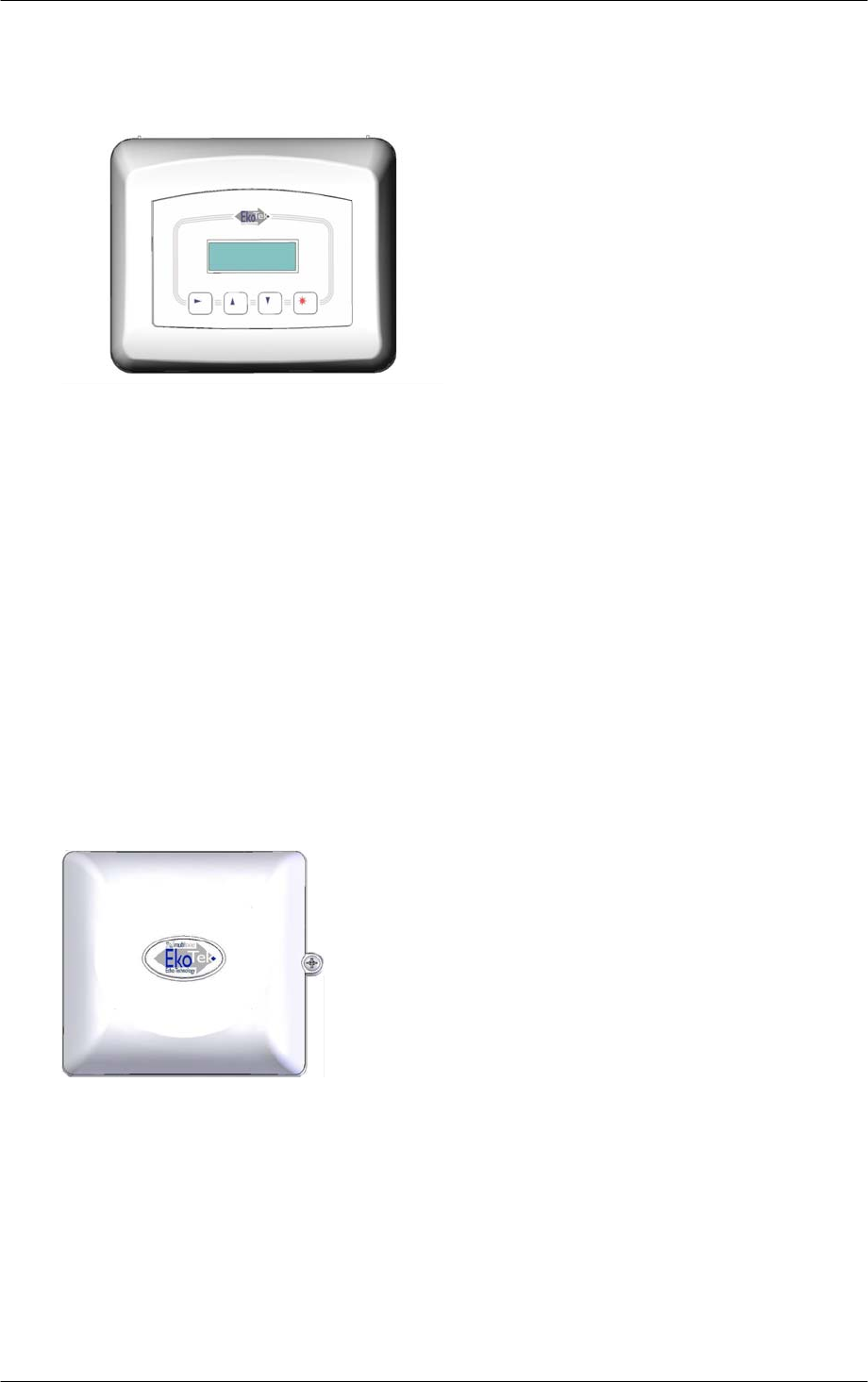
Single Hub
The Hub forms the central device in the mesh network. All communications pass to and
from the Hub, which can be located at any physical point on the network i.e. it can be at
the edge of the network as it does not need to be at the physical centre. See Appendix 2
Specifications on page 50 for specifications.
A Hub display shows alarm messages in a similar way to a two-way Pager.
For configuration, a PC running a web browser is connected via Ethernet to the web
server running on the Hub.
Other connections on the Hub are for alarm relay contacts, external paging systems and
power input.
Internal rechargeable batteries allow the Hub to function for several hours should the AC
power fail.
For more information see 9621-8276 EkoTek Hub User Guide.
Repeater
Repeaters form the backbone of the self-organising radio mesh network. Each Repeater
automatically forms links to nearby Repeaters, to allow messages to pass across the
backbone.
Two screws hold the Repeater on a ceiling or, wall. Two
internal Alkaline `D´ size primary batteries power the
repeater. The voltage is continuously monitored and
reported to the Hub and/or Pagers, raising an alarm
should the voltage fall, requiring that the Repeater
batteries be replaced.
Repeaters also transmit location beacon signals, which
are used by the mobile devices to determine their
location, which is sent when assistance messages are
generated.
Repeaters may form the mesh network in 3 dimensions, with Repeater-Repeater radio
links able to pass via walls and ceilings if necessary.
By default, all Repeaters operate on the same radio channel as the Hub. This is the
default configuration used by most systems and it is not normally necessary to change
from this.
9261-8173 Issue 2 Page 6
© 2007 Multitone Electronics PLC

EkoTek System Installation and Configuration Manual Overview
However, where there is a need to force Repeaters to make links to other specific
Repeaters e.g. when a building-building link is required and this is specifically required to
be above the height of passing vehicles, repeaters can be configured at the Hub to only
operate on specific channels. See the Multitone document “Example EkoTek System
Configurations” for more information on ‘special’ configurations.
Battery replacement is quickly achieved by sliding the repeater from the backing plate and
lifting out the old batteries. No tools are required for this. An optional locking screw can
be inserted where necessary to help prevent tampering with the Repeater e.g. where the
Repeater is installed in a public environment, within reach of passers by.
Repeaters continually test links to adjacent Repeaters, detecting link failures and
automatically searching for and establishing a new links should a one fail.
Network moves and/or expansion are achieved by moving or adding new Repeaters
where required, making any network changes rapid and cost effective.
2-Way Pager
EkoTek’s 2-way Pagers have the following key functions:
• Display of and response to assistance calls from
other 2-way devices
• Display of paging messages created by using the
Hub web server
• Generation of personal security assistance calls
(same as a Call Fob)
For more information see 9621-8275 EkoTek Pager User
Guide.
Display of and Response to Assistance Calls
EkoTek’s 2-way radio network provides message interchange between devices. For
example, when a Call Fob raises an assistance message, this is displayed on Pagers and
the Hub. A Pager/Hub user can then accept the call, which is then signalled back to the
Call Fob and indicated to the User by a change in the LED/beep pattern being emitted by
the Call Fob during the assistance call.
Display of Web server Paging Messages
A two-way paging application runs on the Hub, with paging messages being created via a
page on the web server, using an attached PC and web browser such as Internet
Explorer.
The web server paging display shows when paging messages have been delivered to the
Pager and also the response “Yes/No”. The Pager User is able to send a response to the
message, by pressing the appropriate button on the Pager.
With this two-way paging function, simple task management systems can be easily
created.
Personal Security Calls
In a similar way to Call Fobs, Pagers are able to generate assistance calls using the red
assistance button on the Pager, or the in-built man-down or dead-man functions. A Pager
can therefore function as both an alarm unit and a display, eliminating the need for certain
Users to carry both types of units, as necessary with other types of systems.
Powering
An `AAA´ size battery powers the pager. Either rechargeable NiMH, or disposable
Alkaline batteries may be used. Charging contacts on the Pager are used when the Pager
is inserted into a charging rack.
9261-8173 Issue 2 Page 7
© 2007 Multitone Electronics PLC

EkoTek System Installation and Configuration Manual Overview
Call Fob
The Call Fob allows assistance calls to be raised, using the
location signals from Repeaters for accurate location
determination. The Call Fob also supports dead-man and man-
down features.
The configuration of the Fob is downloaded from the Hub, when t
call fob is powered up. he
The selection of the Call Fob features is by Hub configuration. All
Call Fobs are physically identical and support the same features (if
enabled at the Hub).
An LED, buzzer and vibrate motor are contained within the Call
Fob and are used to indicate the call status, changing when a call is accepted by a remote
user on the Hub, or a 2-way Pager. Indication of "assistance on its way" is signalled in this
way.
An `AAA´ size battery powers the Call Fob. Either rechargeable NiMH, or disposable
Alkaline batteries may be used.
For more information see 9621-8277 EkoTek Call Fob User Guide.
Configuration
Configuration for all devices is held on the Hub and downloaded to each device at power-
up.
The Hub defaults allow a new system to operate ‘out-of-the-box’, only requiring the
location names for the Repeaters to be entered on the Hub web server configuration page.
Each device has it's own unique factory set serial number for identification, but there is no
factory programming of the devices. The Hub configuration set for the devices during
installation, defines whether device options (e.g. man-down) are enabled or not.
Pager addressing is configured at the Hub – there is no need to factory program Pagers.
Network Parameters
An EkoTek system controlled by a single Hub is able to support up to 500 devices. See
Appendix 2 Specifications for maximum numbers for each type of device.
The default configuration is for all EkoTek devices to use the frequency hopping radio
channel used by the Hub, which defaults to channel 15. Other channels can be configured
using the Hub web server interface, with up to 16 channels being available for
simultaneous use by a single EkoTek system and Hub. See the Multitone document
“Example EkoTek System Configurations” for more information on ‘special’ configuration.
A single EkoTek radio channel supports up to 90 Repeaters. The Repeaters can be
configured in any physical deployment, as long as each Repeater is able to establish and
maintain a suitably strong signal with a nearby Repeater, which has a path back to the
Hub.
Repeaters can be deployed in long chain configurations if required e.g. to extend service
along a corridor.
Diagnostics and Statistics
Each EkoTek device collects statistics on network performance and on messages. These
statistics are regularly sent to the Hub and can be viewed using the web server.
Failure (loss) and battery low indications for EkoTek devices are detected by the Hub and
reported on the Hub and/or Pager displays.
9261-8173 Issue 2 Page 8
© 2007 Multitone Electronics PLC

EkoTek System Installation and Configuration Manual
Network Design and Survey
Overview
The survey is used to assess the number of Repeaters required and best locations. It is
suggested that the surveyor reads the System Overview (page 2) to become familiar with
the basic principles of operation.
Pre-requisites
Two survey units
Site plan
Placement Rules
Each Repeater connects to the Hub, either directly or via another Repeater. The number
of Repeaters required is dependant upon the size and layout of the building and the
consistency of the radio coverage.
The EkoTek Hub/Repeaters must not be installed in areas where explosive gas, or dust
products, may be present. Protect the devices from liquids, extreme temperatures and
strong magnetic fields. Do not install in places where they will be exposed to strong
sunlight, or electro-magnetic interference.
Hub
The Hub is normally placed in an area such as a control room or reception
desk, where it is possible to monitor the display when required. Other
considerations are to minimise the number of hops required for any Repeater
to connect to the Hub; it is better if possible that the Hub be located at the centre of
the network. The Hub must be located near to an AC mains socket outlet and it should
also be borne in mind that connection via a modem link to the telephone network may be
required, so access to a telephone socket would also be necessary.
Repeaters
Ideally Repeaters should be spaced 10-15 meters apart. They should be no closer
together than 6 metres, except where there is a structural barrier such as a wall between
Repeaters, sufficient to attenuate the radio signal. The maximum range is 20 metres, but
placing equipments at this distance should be avoided if possible, as any degradation of
the radio path may result in the loss of connection between Repeaters.
Multi-Storey Buildings
The EkoTek can be used in multi-storey buildings, provided that the floors are of concrete
construction. The concrete floor provides sufficient attenuation of the radio signal to
ensure that the Pager/Fob is located on the correct floor. In wooden floored buildings, the
Pager may pick up a beacon from the floor above or below, giving an inaccurate location
for the device.
In order to establish which floor the Pager/Fob is on, it is important that Repeaters are
placed at the entrances to the bottom and top of stairwells. The actual placement of the
Repeater may not necessarily be in the stairwell itself, but in a room leading onto the
stairwell, in order to provide sufficient radio separation between Repeaters.
Corridors
In long corridors it may be prudent to place a Repeater in the middle of the corridor as
well, to ensure robust radio connection in the mesh.
Room Placements
If locating individual rooms, place the Repeater as central to the room as convenient.
Placing it on the edge of the room may allow a sufficient strength of location signal to pass
through the wall, to be seen as a beacon by a Pager/Fob in the adjacent room.
9261-8173 Issue 2 Page 9
© 2007 Multitone Electronics PLC

EkoTek System Installation and Configuration Manual Survey
It is however highly unlikely that the signal would pass through more than one wall.
In large rooms such as warehouses, it may be necessary to place more than one
Repeater to ensure adequate radio coverage.
Between Buildings
If buildings are sufficiently close together, radio signals may pass between them.
However, if for example a vehicle passes between the buildings, it may cause signal
deterioration and the Repeater to loose contact with its parent. On a multi-storey building,
it would be better to force the Repeaters on the first floor to form the link between
buildings, by setting the downstream link of the parent to be a specific channel and the
upstream link of the Repeater to be also the same channel.
Mesh Structure
A Repeater can only have one parent at a time, but the principle of a mesh network is that
if a parent goes down, then the Repeater can look to connect to a new parent to reform
the network. If it is unable to locate a new parent, then the network will be broken. It is
therefore important to ensure that if a Repeater is off, then its "child" has a path to another
parent. In most networks this is not a problem, as a Repeater may see many potential
parents.
9261-8173 Issue 2 Page 10
© 2007 Multitone Electronics PLC
EkoTek System Installation and Configuration Manual Survey
The survey unit
The survey unit is designed to assist in the placement of Repeaters and trouble -shooting
the network. The Pager continuously transmits a signal, either to another Pager or to a
Repeater and measures the signal received from that device.
The left button on the pager scrolls the menus. When taking measurements, always hold
the pager by the left hand side to avoid masking the signal which is transmitted from the
right hand side. Also avoid placing your body between the pager and the measured
device, as this will also attenuate the signal.
Note: The survey Pager is continuously transmitting a signal and the battery life is short.
To avoid unnecessarily draining the battery, remove when not in use.
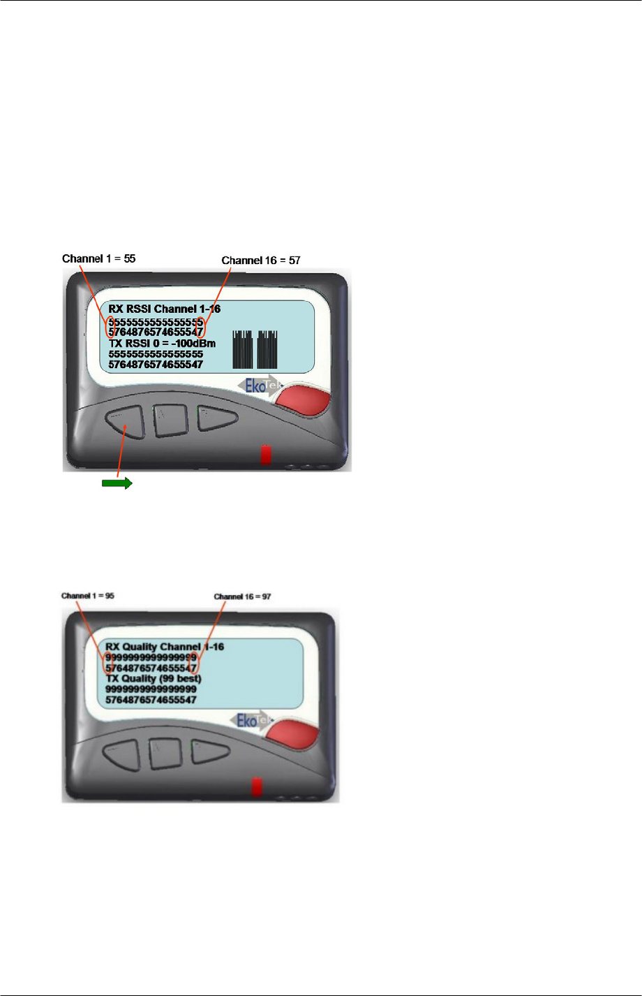
RSSI
This screen indicates the signal strength for each channel in both the RX and TX paths.
The measurement for each channel is displayed as a vertically stacked number. Ideally
the RSSI should be 15 or above.
Quality
This screen indicates the quality for each channel in both the RX and TX paths. The
measurement for each channel is displayed as a vertically stacked number. The range of
reported values is 0 to 99 with 99 being the best quality.
9261-8173 Issue 2 Page 11
© 2007 Multitone Electronics PLC
EkoTek System Installation and Configuration Manual Survey
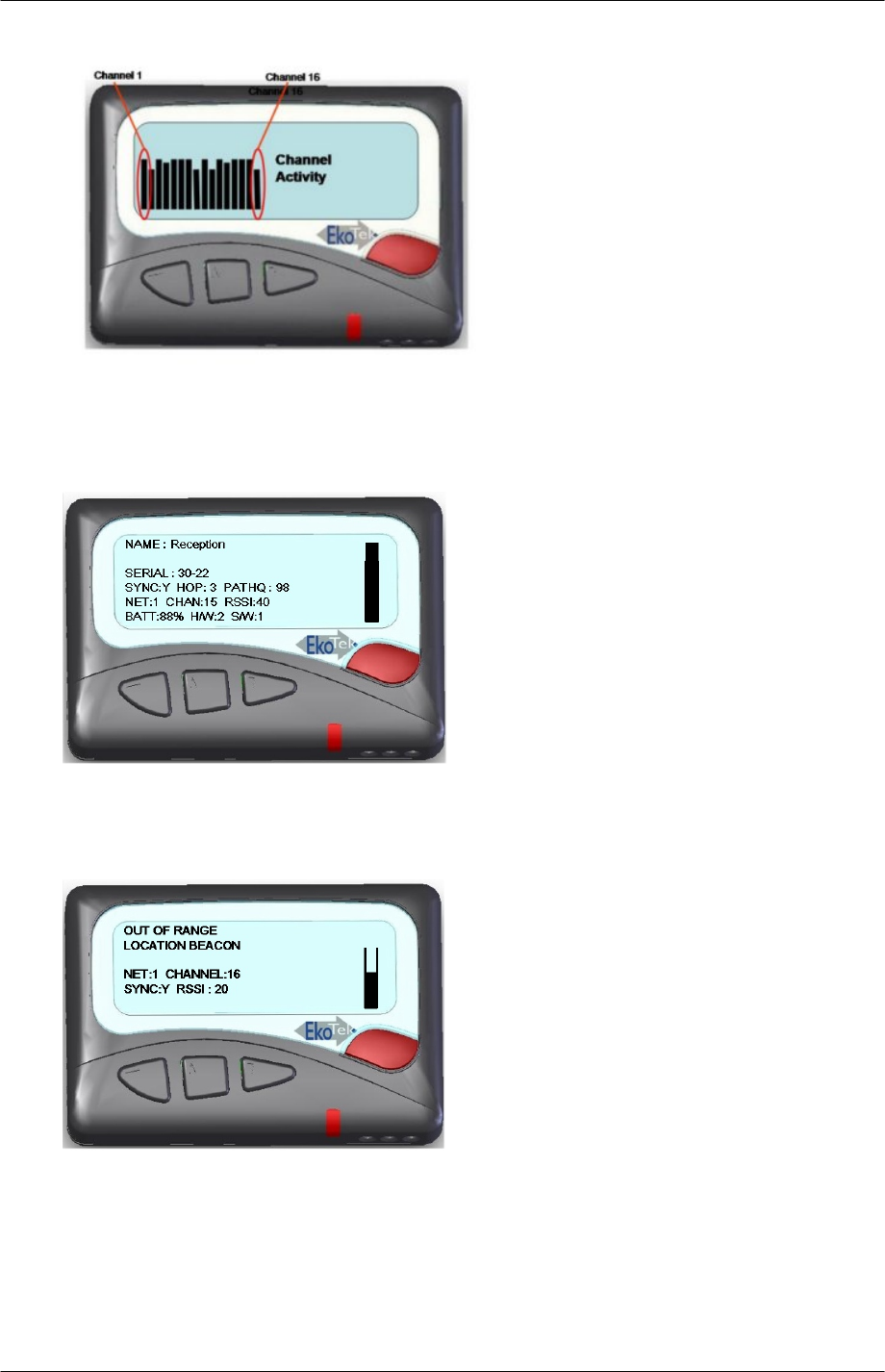
Channel Activity
This shows the activity on each channel and is useful in determining the amount of WiFi
activity on the system.
Repeater Info.
This screen shows information about the Repeater that the survey pager is connected to.
The bar display shows the strength relative to the programmed Repeater location range.
Out of Range Location Beacon
This screen displays information about nearby Repeaters. The bar display shows the
strength relative to the programmed Repeater location range.
How to Survey
Decide on the location for the hub.
9261-8173 Issue 2 Page 12
© 2007 Multitone Electronics PLC

EkoTek System Installation and Configuration Manual Survey
Ask the customer which locations are critical for accurate call location reporting and mark
on the plan those places as locations for Repeaters. It may be every room, a defined area
or different floors. In very large rooms consider the use of more than one Repeater.
Also mark on the plan the positions for Repeaters at the top and bottom of all stairwells, to
allow location tracking between floors.
The customer may also want to have a location change when persons leave a critical
area. If so, mark Repeaters on the site plan at the exit of those critical areas.
When all the likely places for Repeaters have been marked, inspect the site plan to
estimate if the distance between Repeaters exceeds the 10-15 metre maximum separation
rule. If there appears to be a long gap between repeaters, consider if there are Repeaters
on the floor above or below that can form a path for the network.
If a Repeater appears to be isolated, use survey Pagers to check the RSSI. Place a
Pager at the Repeater and measure the RSSI at it's nearest neighbour. Remember it's
nearest neighbour may be on a different floor. If the nearest neighbour is the other side of
a thick wall, other marked locations may provide a more viable route. If in doubt it is best
to place in-fill Repeaters, as the more Repeaters in a network the more robust the network
is liable to be. If the RSSI is below 20, then consider placing another Repeater in
between.
9261-8173 Issue 2 Page 13
© 2007 Multitone Electronics PLC

EkoTek System Installation and Configuration Manual
Installation
Pre-requisites
Prior to installation, the following items are needed:
• Site Plan with the position of the Hub and all the Repeaters clearly marked.
• An AC mains socket outlet for the Hub.
• An Ethernet connection to the LAN or dedicated PC.
• A working telephone line and AC mains socket for the PPP connection.
• A line for TAP connection if required.
Tools required
• Pozidrive screwdriver with PH1 bit.
• Screwdriver with 2.5mm blade.
• Stepladder.
• Cordless drill with 5mm masonry bit.
• Metric ruler.
• Laptop with Ethernet port.
• Ethernet patch cable.
• Fob and pager.
• It may also be useful to have a survey unit.
Parts required
EkoTek Hub with AC supply unit.
US robotics 5630D modem with AC supply unit and a RS232 (proprietary) connecting
lead. See RS232 Connecting Lead.
EkoTek repeaters: Quantity as required by survey. It is also suggested that a spare
Repeater is supplied, in case there is a need for in-fill that was not detected on the
survey.
9261-8173 Issue 2 Page 14
© 2007 Multitone Electronics PLC
EkoTek System Installation and Configuration Manual Installation
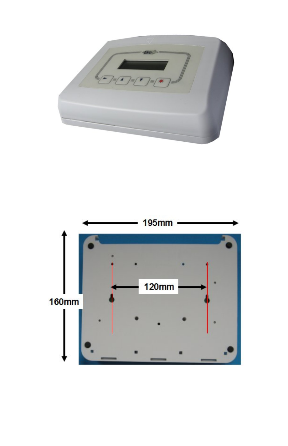
Installing the Hub
Figure 6. Hub
The Hub can be freestanding on a desk, or wall mounted using the screws provided.
To remove the cover, depress the two protruding plastic tabs and separate the top from
the back plate.
Wall Mounting
Mark the position of the screws on the wall. The two screws should be spaced precisely
120mm apart.
Figure 7. Hub Back Plate
Drill two holes with a 5mm masonry bit to a depth of 25mm.
Insert the wall plugs and screw the screws in using a PH1 Pozidrive bit. Leave 7mm of the
screw protruding.
Locate the screw heads in the holes in the back-plate and pull the unit down to lock into
place.
9261-8173 Issue 2 Page 15
© 2007 Multitone Electronics PLC
EkoTek System Installation and Configuration Manual Installation
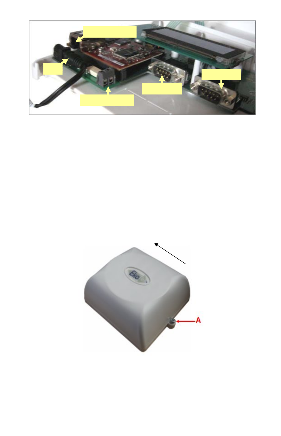
Interface Connections
DC
Ethernet
(RJ45)
Alarm Output
TAP
(DB9)
PPP
(DB9)
Figure 8. Interface Connections
Plug in the AC to DC power adapter
Plug in the Ethernet patch lead to connect to the LAN or PC. See also Connect the Hub to
the PC using Windows XP (page 23).
If an external alarm is to be activated from the Hub, connect a pair of wires from the alarm
output shown in Figure 8. Interface Connections. The alarm output is a simple make
contact and can be used to operate a customer provided alarm relay. This is not designed
to provide a direct contact for AC mains operated equipment.
Connect the DB9 TAP connection to the customer's paging system if required. The
connection cable should be as specified by the paging system.
The PPP connection is made after the modem has been set-up. See
PPP Modem (page 17) for further details.
Repeaters
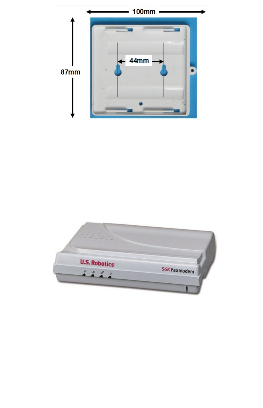
Figure 9. Repeater
Mounting the Repeater
Remove the back plate from the Repeater by sliding it in the direction shown.
Use the back plate to mark the position of the screw holes on the wall or ceiling.
9261-8173 Issue 2 Page 16
© 2007 Multitone Electronics PLC
EkoTek System Installation and Configuration Manual Installation
Figure 10. Repeater Back Plate
If fixing to masonry, drill two holes with a 5mm masonry bit to a depth of 25mm and insert
wall plugs.
Screw the back plate in position using a PH1 Pozidrive bit.
Ensure the batteries are in place and slide the Repeater into position.
Lock the Repeater (if required) by screwing the small screw provided in the installation
parts, as indicated by A in the photo above
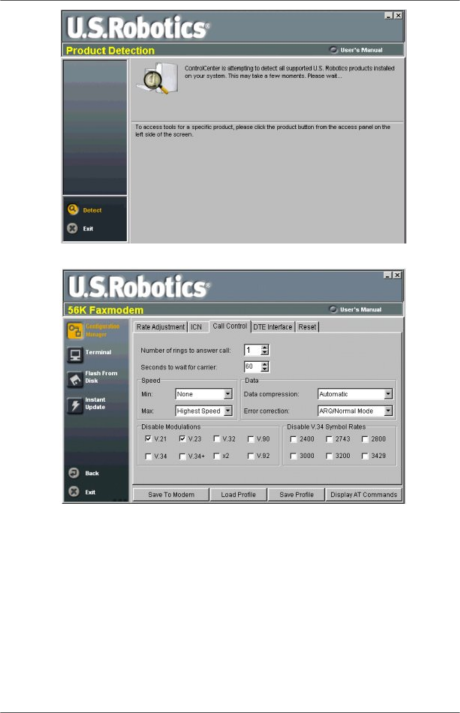
PPP Modem
PPP connection to the Hub is made using a US robotics 5630D modem.
1. Plug the modem into the serial port of a PC using the serial interface cable provided
with the modem. Use an adapter if the PC does not have a serial port. See
Appendix 3 (page 51) for details of cable pinouts.
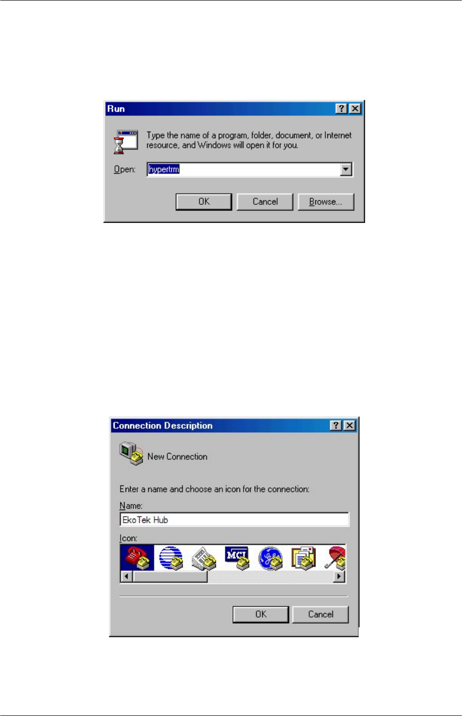
2. Install the US Robotics software onto the PC, from the CD provided with the modem.
3. After installation, locate the software in the programs menu on the PC and start.
The software automatically detects if the modem is connected.
9261-8173 Issue 2 Page 17
© 2007 Multitone Electronics PLC
EkoTek System Installation and Configuration Manual Installation
Click the Configuration Manager and go to the Call Control tab
Set the Number of rings to answer call box to 1.
Click the Save to Modem button, which stores the current values from the Configuration
Manager's fields to the writable memory of the modem.
Using Windows Hyper Terminal to Set Interface Speed
A terminal program is an application that will enable a PC to communicate directly with a
modem. If you are using Windows 2000 or Windows XP, you can use the Windows
HyperTerminal program as it is included as part of the operating system.
1. Check that the modem is connected to a serial port on the PC.
9261-8173 Issue 2 Page 18
© 2007 Multitone Electronics PLC
EkoTek System Installation and Configuration Manual Installation
2. Load HyperTerminal:
• Click Start > Run
• In the box which appears, type in: HYPERTRM
• Click OK.
If you see the error message 'Cannot find HYPERTRM' you will need to install
HyperTerminal:
• Click Start > Settings > Control Panel > Add / Remove Programs.
• In Add / Remove Programs select Properties and then click the Windows Setup tab.
• Double-click Communications
• Check the box for HyperTerminal
• Click OK, and then OK again to install.
• Note: You may be asked for your Windows installation disk for this procedure.
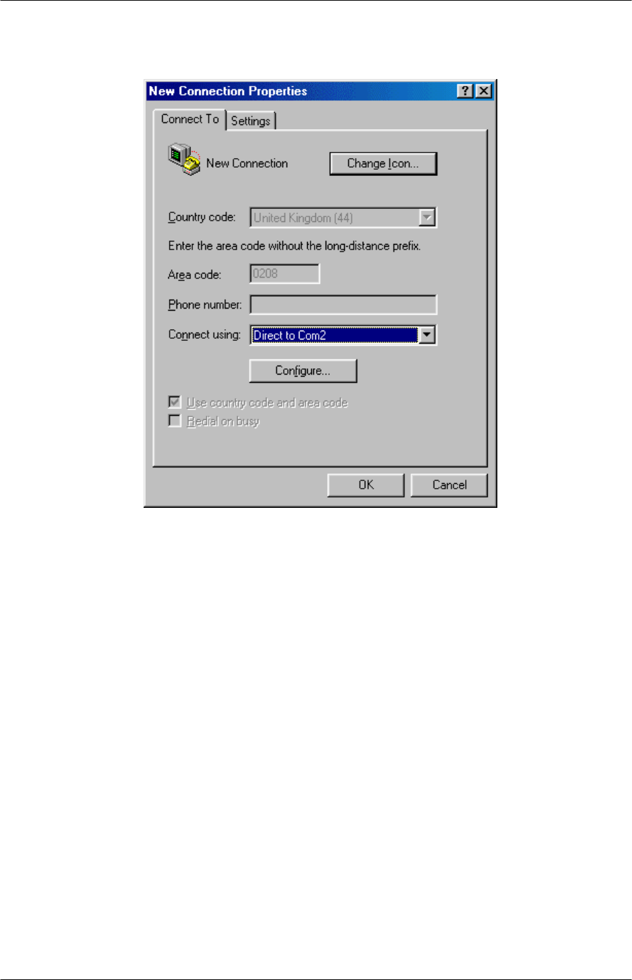
3. When HyperTerminal starts you will be presented with a 'Connection Description'
dialogue box.
• Click 'Cancel' to continue.
4. Select your COM Port:
• Select 'File' then 'Properties' from the menu bar and the 'New Connection
Properties' window will open.
• Click on the arrow for the 'Connect Using' drop down box.
9261-8173 Issue 2 Page 19
© 2007 Multitone Electronics PLC
EkoTek System Installation and Configuration Manual Installation
• Select 'Direct to ComX' (where X is the COM Port you are using to connect the
modem. - e.g. COM1, or COM5, etc).
• Click OK.
9261-8173 Issue 2 Page 20
© 2007 Multitone Electronics PLC
EkoTek System Installation and Configuration Manual Installation
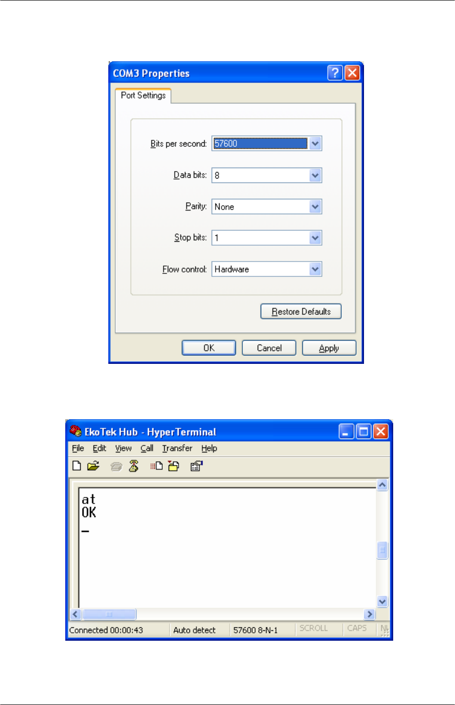
• Configure the port to set the interface speed to 57600.
5. Click OK - a blank terminal window will open. You should now be communicating
directly between the COMPORT and modem. To confirm this, type in the two letters
'AT' and press 'enter'
• Type in 'AT' (Enter)
If you are communicating, the modem will reply with 'OK'. If so, proceed to Step 6.
9261-8173 Issue 2 Page 21
© 2007 Multitone Electronics PLC
EkoTek System Installation and Configuration Manual Installation
If no 'AT' or 'OK' appears, then there is a basic communication issue between the PC
and the modem - most likely the COMPORT selected is incorrect - check this and try
again.
If problems persist:
• Check Windows Device Manager (where available):
• Check that the Modem is installed.
• Check the COM Port is enabled and has no clashes (indicated by a yellow
exclamation mark next to it).
• Check the COMPORT is enabled in the system BIOS setup.
6. To store the configuration of the port speed in the modem, type 'AD&B2&W' and
press 'Enter'. You should receive an 'OK' as a response.
7. Remove the lead from the PC COM port and connect to the PPP socket on the Hub.
8. Close the cover on the Hub. Ensure that the ribbon for the keypad is connected to the
header on the daughter board, as this is sometimes dislodged when the cover is
removed.
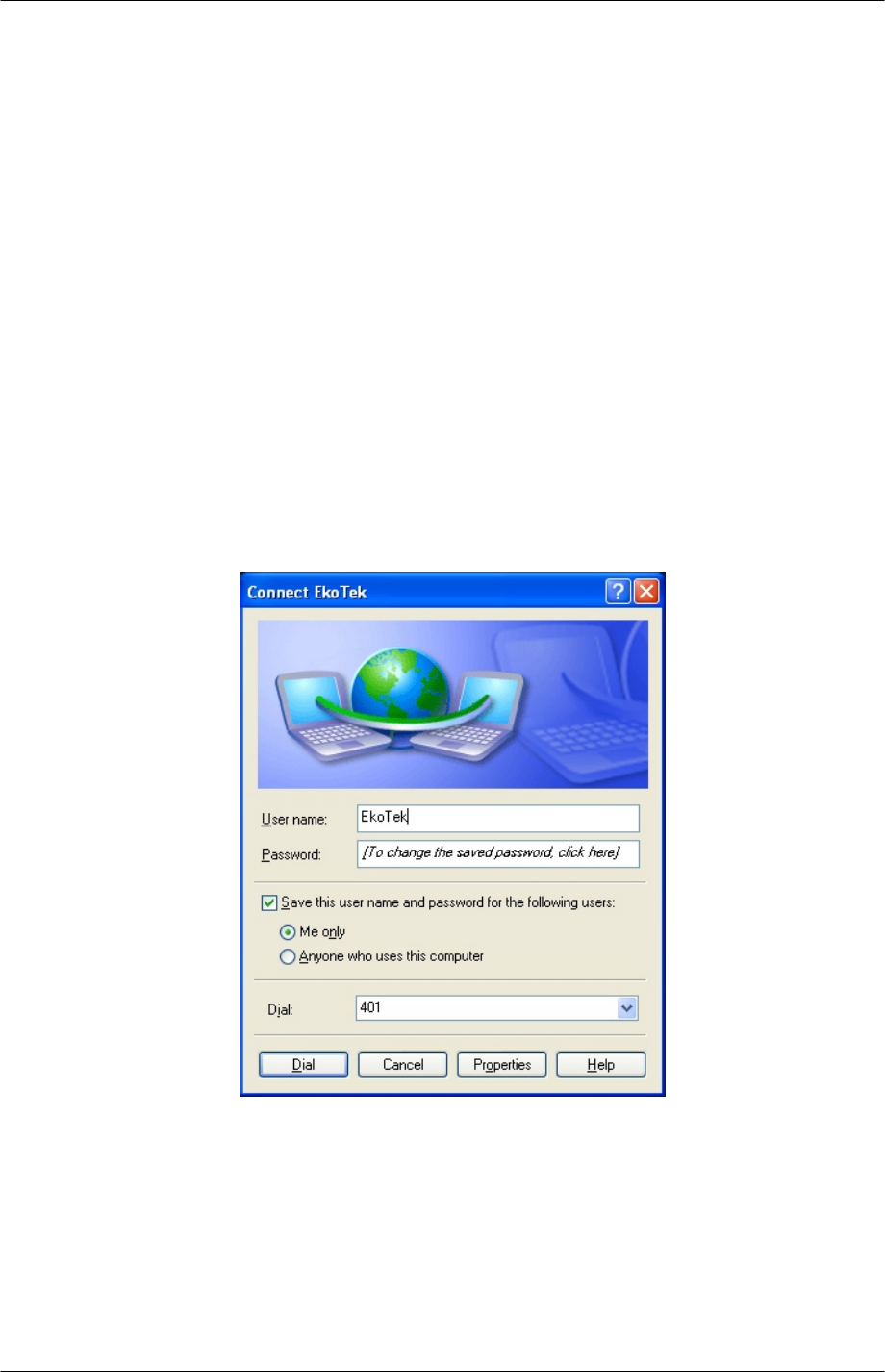
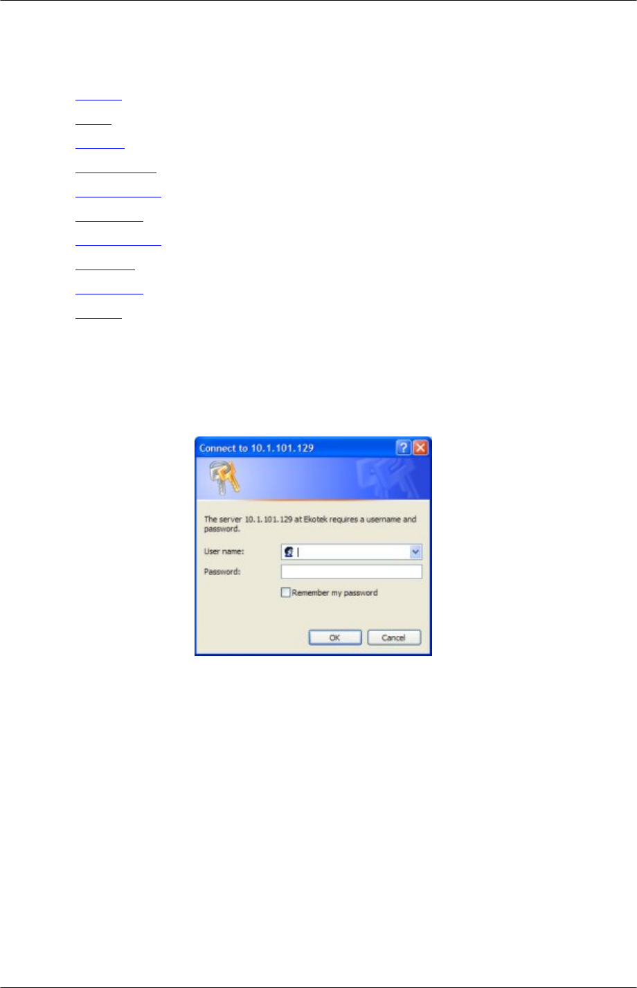
9. Test by dialling in to the modem from a PC. The User name and Passwords are both
‘EkoTek’. The modem should auto answer and the EkoTek menu screen should be
displayed.
10. Set up system configuration using the browser as described in the next section
9261-8173 Issue 2 Page 22
© 2007 Multitone Electronics PLC
EkoTek System Installation and Configuration Manual
The Browser Interface
Accessing the HUB with the browser interface
In order to configure and setup the Hub, a PC or a network Ethernet connection needs to
be made to the Hub. This connection can also be used to monitor the EkoTek network.
Once the connection has been made, then communication with the Hub is achieved
through a web browser.
DC
Ethernet
(RJ45)
Alarm Output
TAP
(DB9)
PPP
(DB9)
Figure 11. Hub Interfaces
Connect the Hub to the PC using Windows XP
On the PC: -
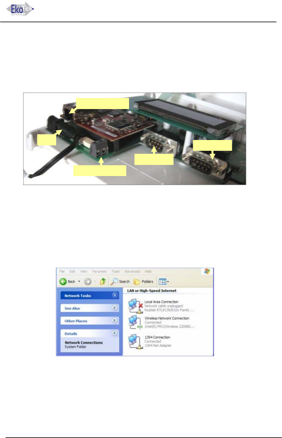
1. Click the Windows start menu and select Control Panel.
2. Click ‘Network and Internet connections.
3. Click Network Connections. With the network cable disconnected, the Local Area
connection will be shown as unplugged (X).
4. Open the Hub. To open the Hub, push the two locking tabs in and then separate the
cover from the back plate.
5. Connect an Ethernet (RJ45) patch cable to the RJ45 connector, See Figure 11. Hub
Interfaces.
6. Connect the other end of the patch cable to the Ethernet (RJ45) connector on the PC.
9261-8173 Issue 2 Page 23
© 2007 Multitone Electronics PLC
EkoTek System Installation and Configuration Manual Browser Interface
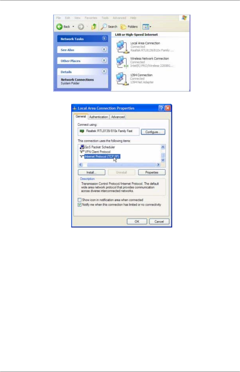
7. If connected correctly the screen will change to show the cable connected.
8. Double click the Local area connection icon to open the properties window.
9. Scroll the new window and select the ‘Internet Protocol TCP/IP’ menu item.
10. Click the Properties button.
9261-8173 Issue 2 Page 24
© 2007 Multitone Electronics PLC
EkoTek System Installation and Configuration Manual Browser Interface
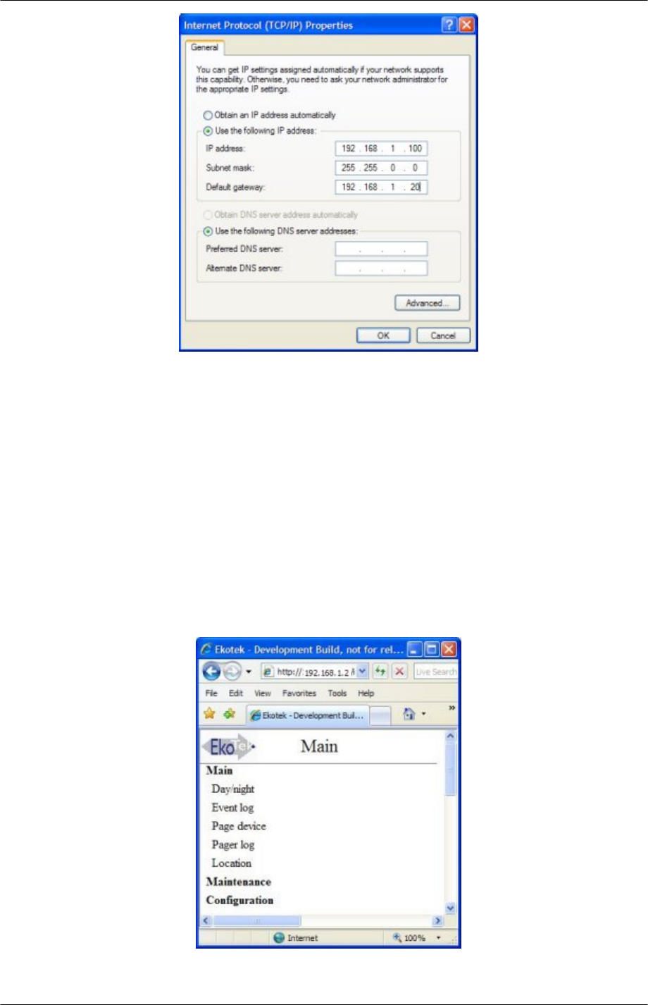
11. The default shipped configuration for the Hub is: -
IP address: 192.168.1.2 (1.1.1.1 if via PPP serial port)
Subnet mask: 255.255.0.0
Default gateway: 192.168.1.20
In order to communicate between the PC and the Hub, the IP address of the PC has
to be set to the same Network and Subnet as the Hub. To achieve this select ‘Use
the following IP address’ and enter the IP address in the same range as the Hub (in
the example above 192.168.1.100 and a subnet mask of 255.255.0.0 Gateway
192.188.1.20).
12. Click OK to finish.
Using the Web Browser to Access the EkoTek Hub
In the address field of the web browser, type the IP address of the Hub (default is
192.168.1.2 for ethernet) and click the refresh button. The browser then connects to the
Hub web interface.
9261-8173 Issue 2 Page 25
© 2007 Multitone Electronics PLC
EkoTek System Installation and Configuration Manual Browser Interface
Main menus
Day/Night
Event Log
Page Device
Pager Log
Location
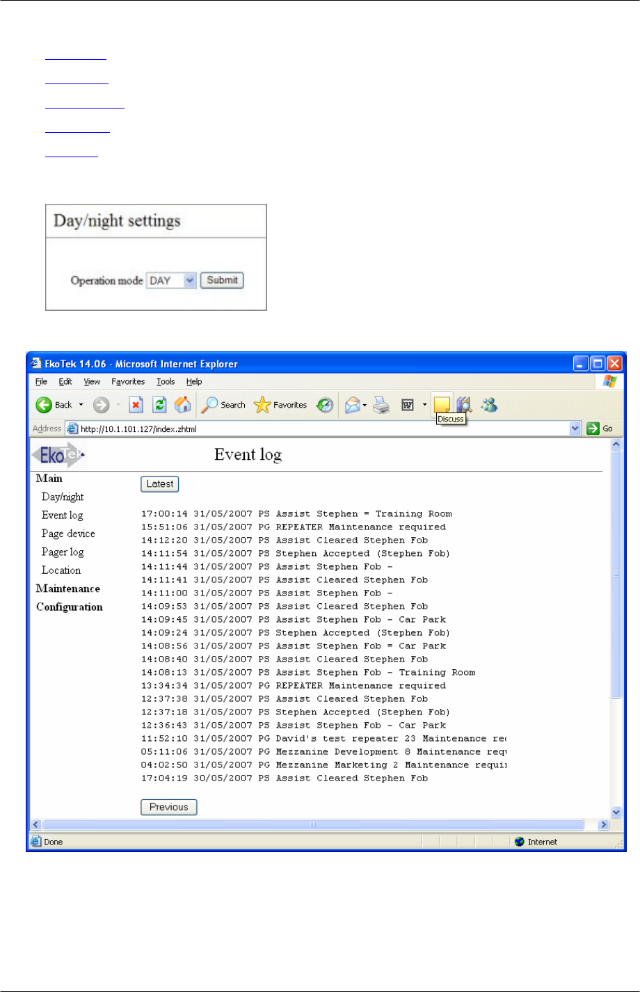
Day/Night
Event Log
keeps track of all events on the system. It records: -
he time and date for each event recorded.
The event log
T
PS = Personal security.
PG = Paging application.
9261-8173 Issue 2 Page 26
© 2007 Multitone Electronics PLC
EkoTek System Installation and Configuration Manual Browser Interface
Type of event and event
The event log –stores the
details
last 9000 events in flash memory, each event being a pager
here delivery/user response is requested any message
arliest
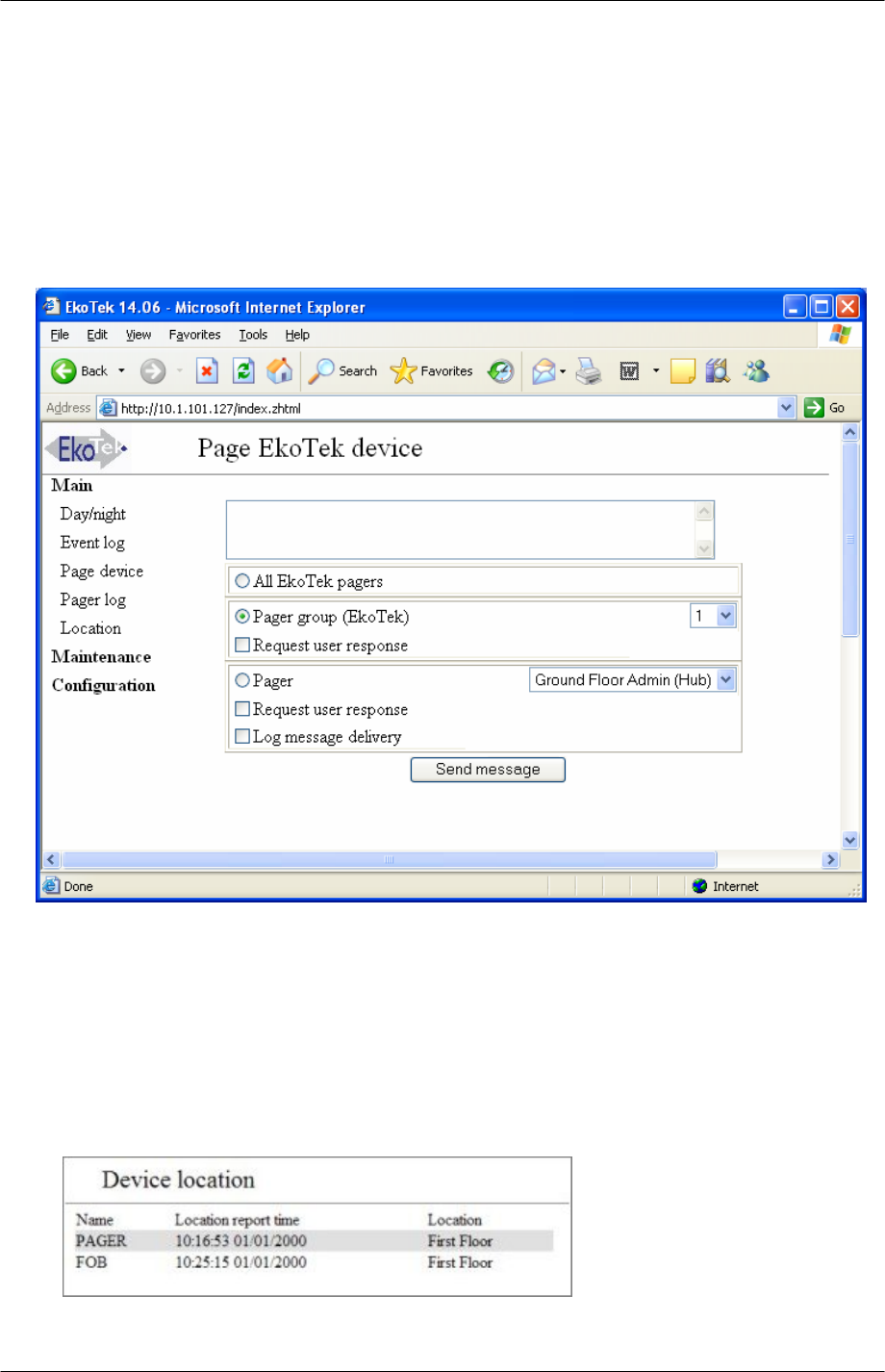
Page Device
Pager Log
ores the last fifteen Pager messages, which had either, log message
elivery, or request user response, ticked. Messages are kept until the sixteenth new
e with response/delivery request ticked, or if Hub is reset.
ger messages are also written into the event log.
Lo
message sent (and in the case w
delivery/user responses), or an alarm being raised/accepted/cleared maintenance
message (i.e. device with low battery/not reporting its status).
Once 9000 events have been recorded, any new event received is stored and the e
recorded event is removed from the log.
The pager log st
d
messag
Note: The pa
cation
9261-8173 Issue 2 Page 27
© 2007 Multitone Electronics PLC

EkoTek System Installation and Configuration Manual Browser Interface
If location r
Location sc
eporting for mobile devices has been enabled under the device mode, the
reen shows the last location report ed by each mobile device.
9261-8173 Issue 2 Page 28
© 2007 Multitone Electronics PLC
EkoTek System Installation and Configuration Manual Browser Interface
Maintenance Menus
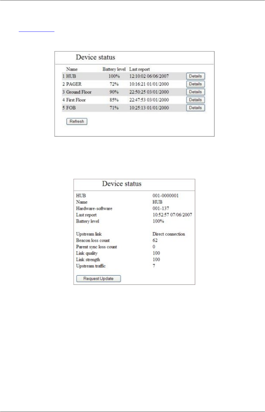
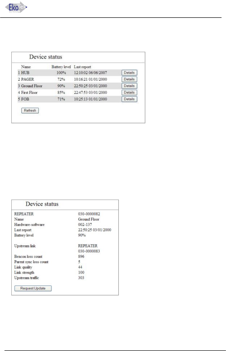
Device Status
Device Status
Each device in the mesh connects to the Hub via a parent device (repeater or directly to
the hub itself). Maintaining this connection is important. These stats relate to that
connection. Status reports are made every 4 hours.
Device Status Hub
Hub: Serial Number.
Name: Name given to device.
Hardware-Software: Revision number.
Last Report: Time and date stamp.
Battery Level: For Hub will always be 100.
Upstream Link: The name of the parent device to which the local device is connected by
the radio mesh (reported on the Hub as ‘Direct connection’).
Beacon loss count = this records beacons lost during start up/reset.
Parent sync loss = number of times that a loss of sync has occurred.
Link quality = general quality of link to parent, Scale 1 to 100 where 100=best.
Link strength = RSSI of parent link, Scale 1 to 100 where 100=best.
Upstream traffic = count of packets sent to parent.
9261-8173 Issue 2 Page 29
© 2007 Multitone Electronics PLC
EkoTek System Installation and Configuration Manual Browser Interface
The stats are simple incrementing counters.
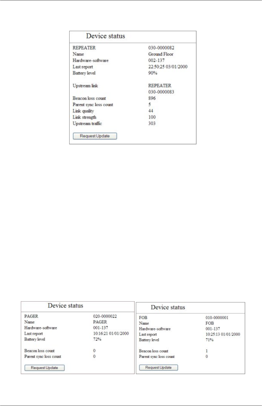
Device Status Repeaters
Repeater: Serial Number.
Name: Name given to device.
Hardware-Software: Revision number.
Last Report: Time and date stamp.
Battery Level: Shows battery level. An alarm is given when battery level drops to 20% and
a replace battery message initiated at 5%.
Upstream Link: Name and serial number of Repeater or Hub connected to.
Beacon loss count = missed parent beacons. This counts the number of times the
Repeater has lost contact with its parent, either through faulty parent or degradation of the
signal to the parent.
Parent sync loss = number of times that a loss of sync with parent has occurred.
Link quality = general quality of link to parent. Scale 1 to 100 where 100=best.
Link strength = RSSI of parent link. Scale 1 to 100 where 100=best.
Upstream traffic = count of packets sent to parent.
The stats are simple incrementing counters.
Device Status Fob and Pager
Pager/Fob: Serial Number.
Name: Name given to device.
9261-8173 Issue 2 Page 30
© 2007 Multitone Electronics PLC

EkoTek System Installation and Configuration Manual Browser Interface
Hardware-Software: Revision number.
Last Report: Time and date stamp.
Battery Level: Shows battery level regardless of whether the mobile battery level monitor
is set to on or off. See Mobile device monitor (page 35).
Beacon loss count = missed parent beacons. This counts the number of times the
Repeater has lost contact with its parent either, through faulty parent or degradation of the
signal through moving out of range of the Repeaters.
Parent sync loss = number of times that a loss of sync with parent has occurred.
Request Update: click to retrieve current stats.
9261-8173 Issue 2 Page 31
© 2007 Multitone Electronics PLC
EkoTek System Installation and Configuration Manual Browser Interface
Configuration menus
The EkoTek configuration menus are: -
System
Radio
Devices
Device Mode
Pager Groups
Alert Rules
Factory Reset
Delete All
Passwords
Archive
Password
When a configuration menu item is opened at the beginning of a session, a password is
requested. The default is user: admin and the password is not set (blank). Once access
is gained the password can be set as required.
9261-8173 Issue 2 Page 32
© 2007 Multitone Electronics PLC
EkoTek System Installation and Configuration Manual Browser Interface
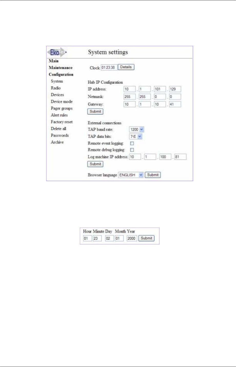
System Settings
This page sets the network interfaces. It enables set up of Hub settings, clock, external
connections and the browser language.
Click ‘Configuration’ and select ‘system’.
Set Clock
The clock operates in two modes, one displaying the current time (if JavaScript is enabled
on the browser this will update, if not then the clock is a snapshot of the time the page was
loaded).
1. Click the details button and enter the current time and date.
2. Click submit to set.
Note: An illegal clock setting will return to clock display mode, but the original settings will
be retained.
Hub IP configuration
If the Hub is to be connected to an Ethernet Server/Network, then the IP address, subnet
mask and gateway should be set within the address range of the network, to allow the Hub
to be accessed from the network. Once the IP address is configured, then the Hub can
only be accessed using that IP address, so a note should be made of any IP address that
is set.
Note: An illegal IP setting will return to system settings and the original settings will be
retained.
9261-8173 Issue 2 Page 33
© 2007 Multitone Electronics PLC
EkoTek System Installation and Configuration Manual Browser Interface
External Connections
Section for setting up external paging and logging connections.
Tap connection
If the Hub is to be connected to a wide area-paging network, then a modem is connected
to the serial port. The data rate should be set to the modem speed (Options 1200, 2400
and 9600 bits per second). The data format should be set to match that of the receiving
device (Options 7 bit even parity or 8 bit no parity)
Remote Logging
1. Click ‘Remote event logging’ to allow system event messages be sent to a remote
device.
2. Click ‘Remote debug logging’ to forward all received/transmitted messages to remote
machine.
3. Set the IP address of remote logging machine (logging messages sent to port 514) of
the remote computer. Click submit to set the new external connection settings.
Note: No check is made that the remote logging machine exists.
Language
The browser interface is available in English, French (Francais), or Spanish (Español).
Select required language from the drop list and click ‘Submit’
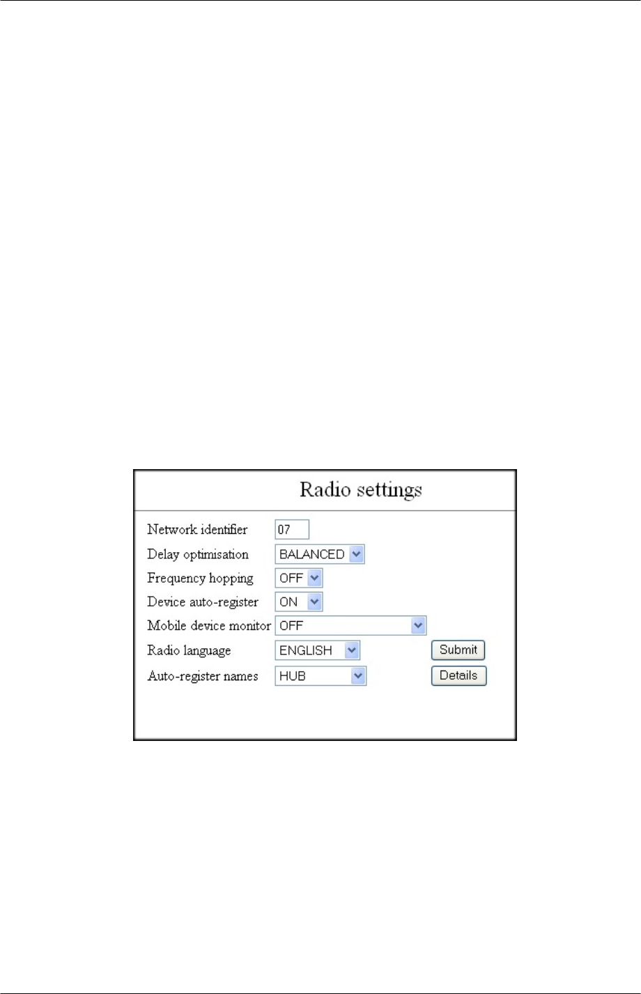
Radio Settings
Network identifier
The network identifier enables mobile devices to detect movement between EkoTek
systems, forcing them to re-request their config. from the Hub. An example application is
where a customer has two sites - each site should be set with a different identifier, so that
when employees move between sites their mobile device will obtain the local config. when
the device moves to a new site. The default is 01.
Note: Overlapping EkoTek networks are not supported in the first release.
Delay optimisation
Options: Inbound or balanced.
9261-8173 Issue 2 Page 34
© 2007 Multitone Electronics PLC

EkoTek System Installation and Configuration Manual Browser Interface
Inbound is used for maximum speed of delivery in the direction towards the Hub and is
normally only used when there are no Pagers on the network i.e. no outbound user
messaging (useful if external paging is intended as the main method of alerting users, or
the German specification system).
Balanced is used where there are EkoTek Pagers on the system, to give a balanced
speed of message flow across the radio network, both towards and from the Hub.
Balanced is fine for most applications and is the default.
Frequency hopping.
The 2.4GHz WiFi band has 16 channels. Frequency hopping allows the radio to change
frequency (hop) between different channels in the band. This helps the system avoid
interference from other WiFi devices using the spectrum and offers more security from
eavesdropping, if this is a consideration.
The system can also be set to use a fixed frequency.
Usually only the first 14 channels are used for WIFI systems and setting to use a single
fixed frequency in channels 15 or 16 could prove to be more robust where there is heavy
WiFi usage. Set to ‘on’ or ‘off’ as required.
Device auto-register
If device auto register is set to ‘on’, any unknown device that is detected is permitted to
join the network. These devices will be given default names. If the auto register is set to
‘off’, devices need to be manually added to the database before they will be recognised as
on the system.
Mobile device monitor
All Repeaters are automatically monitored for battery condition and presence on the
network, with Paging messages generated on low battery or absence of the device from
the network. Mobile devices (Pagers and Fobs) can also be monitored for battery
condition and presence on the network . Set to ‘OFF’, ‘BATTERY’ ,
‘NETWORK+BATTERY’ as required.
Note: The battery condition will be displayed on the Device status page, regardless of this
setting.
Radio language
The Pager display language is available in English, French (Francais), or Spanish
(Español). Select required language from the drop list and click ‘Submit’.
Auto-register names
When the network detects a device, it is given a default name appropriate to the device
type: Hub, Repeater, Pager or Fob. This default name can be redefined if required.
Select device from the drop list and click ‘Details’. Enter a new name for the default and
click submit to set. For example, to set all Pagers to register as ‘Staff’ and all Fobs as
‘Visitor’.
9261-8173 Issue 2 Page 35
© 2007 Multitone Electronics PLC
EkoTek System Installation and Configuration Manual Browser Interface
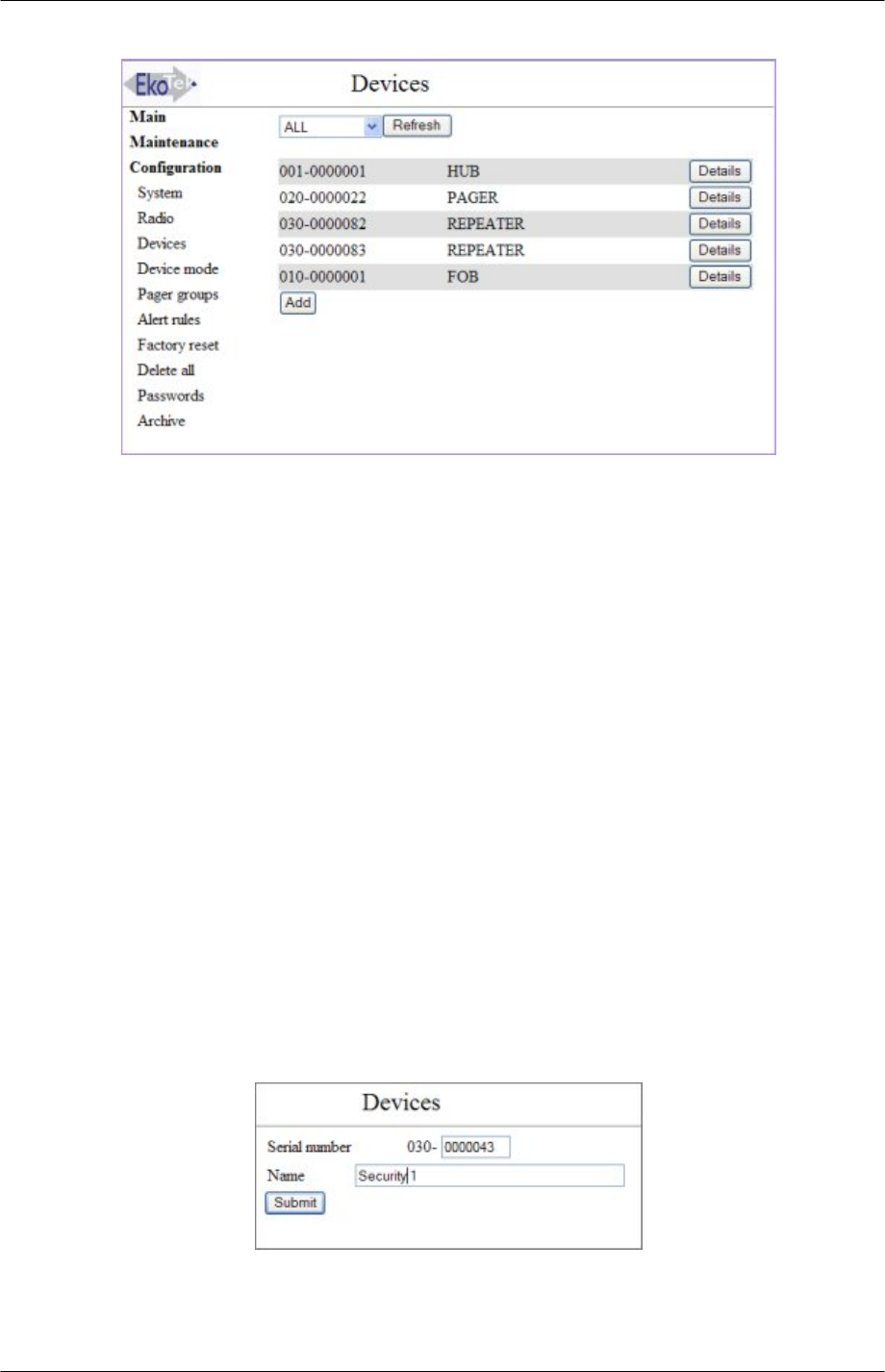
Devices
The overview page lists all the devices connected in the EkoTek network.
Refresh:
To get the current list of devices, select the hardware type to be listed from the drop list
and click the ‘Refresh’ button.
The devices will then be listed; the first column gives the hardware type-serial number of
the device, the second column gives the device name and the third provides a "Details"
button, to go to that specific device’s record.
The serial number of each device is displayed and the device name.
001-xxxxxxx indicates a hub
010-xxxxxxx indicates a fob
020-xxxxxxx indicates a pager
030-xxxxxxx indicates a repeater
Click the ‘Details’ button to see the details of any device.
Add
Click ‘add’ to go to the `add a new device´ entry pages.
1. Select device type from menu.
2. Enter serial box and enter the serial number and name. The entry screen below is for
a Repeater. Similar screens are shown for Hub, Fob and Pager, with the appropriate
hardware code displayed.
3. Submit: Click to add the new device. If valid, then the individual device entry page is
displayed. If not possible (invalid serial number length, attempt to add a device prior
to the Hub, attempt to add a second Hub, too many devices already on-system etc.)
then ‘Invalid device request’ is displayed. If a device exists in the database with the
9261-8173 Issue 2 Page 36
© 2007 Multitone Electronics PLC
EkoTek System Installation and Configuration Manual Browser Interface
same serial number as the new requested device, the existing device details will be
displayed.
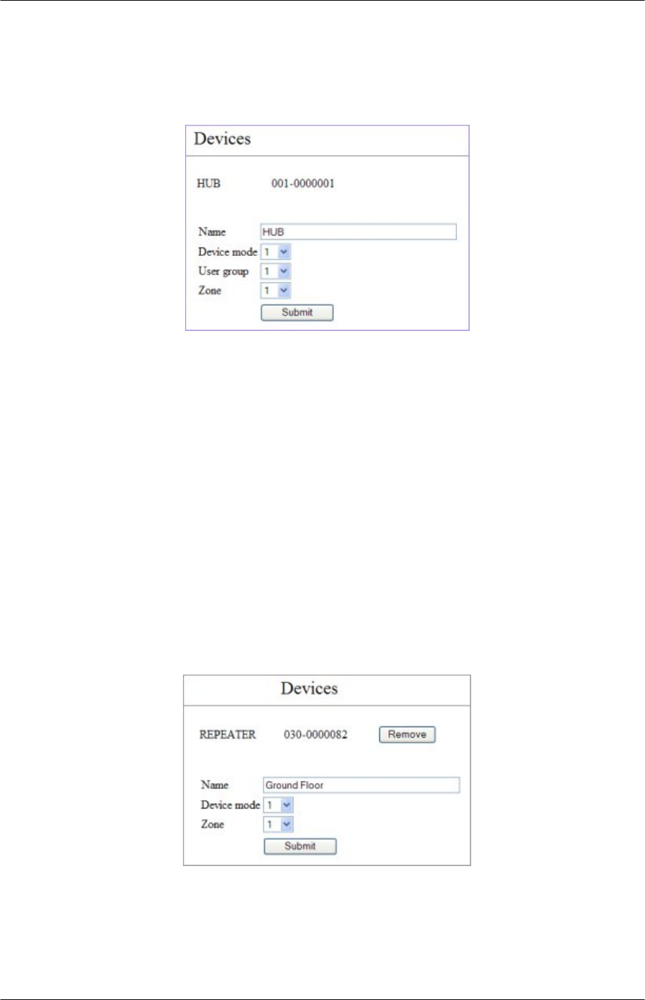
Details
Hub
Name
The name of the Hub may be changed, by entering a new name in the box.
Device mode
Each Pager and Fob is allocated a device mode (1-32). The device mode defines the
alarms and responses to them. See Device Mode (page 38).
User group
Select from the drop list, to set User group 1-16.
Zone
Fixed devices are allocated a Zone number, allowing assist messages from mobile
devices to be sent to different Pager groups, based on the Repeater (Zone) that the
mobile device is connected to. Up to 16 zones are supported by the EkoTek system.
Submit
Click Submit to enter changes.
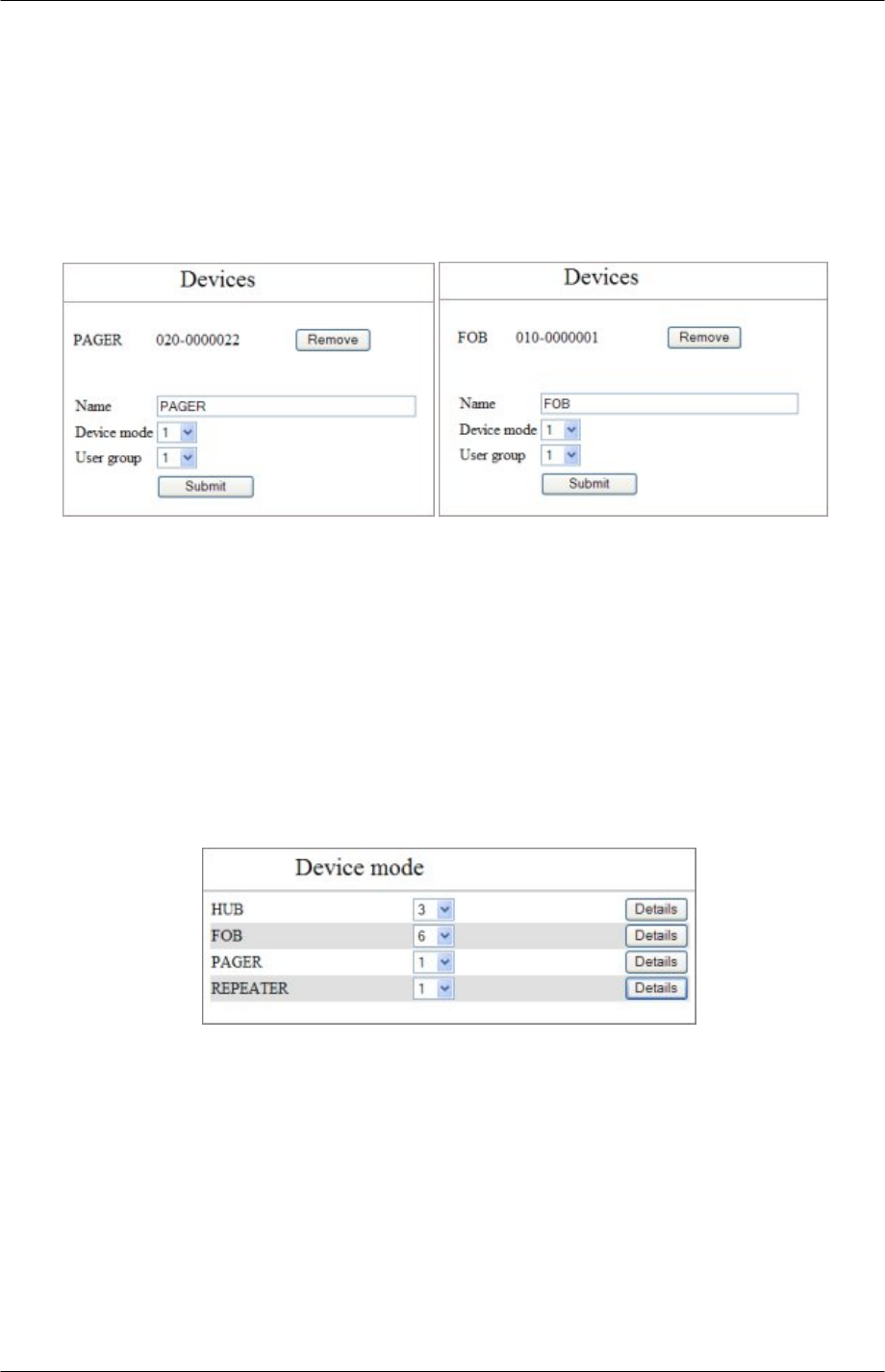
Repeater
The name of the Repeater may be changed, by entering a new name in the box.
Device mode
Each Repeater is allocated a device mode (1-32). The device mode defines the
alarms and responses to them. See Device Mode (page 38).
9261-8173 Issue 2 Page 37
© 2007 Multitone Electronics PLC
EkoTek System Installation and Configuration Manual Browser Interface
Zone
Each Repeater is allocated a zone. Repeaters set with the same zone will all connect
to that Hub. This ensures that when a repeater is within the mesh of more than one
Hub, it is forced onto the required Hub. Up to 16 zones are supported by the EkoTek
system.
Submit
Click Submit to enter changes.
Pager and Fob
Name
The name of the Pager/Fob may be changed, by entering a new name in the box.
Device mode
Each Pager and Fob is allocated a device mode (1-32). The device mode defines the
alarms and responses to them. See Device Mode (page 38).
User group
Select from drop list to set User group (1-16).
Submit
Click Submit to enter changes.
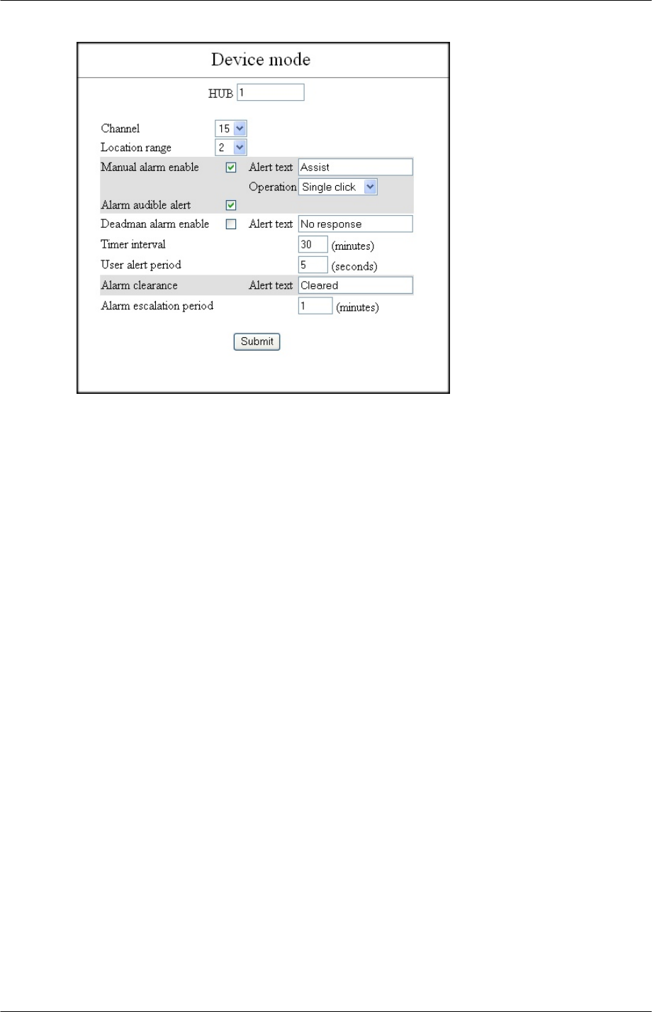
Device Mode
This section allows changes to be made to device parameters. The initial page presents a
list of the different hardware types. A drop down menu allows selection of a specific
device mode (1-32) for the hardware type and a details button, which re-directs the
browser to the specific hardware device mode (HUB, FOB, PAGER, REPEATER).
9261-8173 Issue 2 Page 38
© 2007 Multitone Electronics PLC
EkoTek System Installation and Configuration Manual Browser Interface
Hub Details
The device mode entry page hardware type is followed by the modifiable device mode
name (defaults 1->32).
Channel:
Select from the drop down menu (1 -> 16) to set the RF channel to be used by the Hub.
The default value of 15 should be sued where possible.
Location range:
Defines the range of the location signal from the Hub. The default value is ‘2’ which gives
an approximate range in indoor environments of 3m. A value of ‘1’ gives the shortest
range and ‘10’ the longest range. The range should not be set to high values in
deployments where location signal penetration through walls and floors is not desired.
Manual alarm enable:
Set the manual alarm and ways the device can raise manual alarms, i.e. via button
press(es).
Alert text:
Modify text to define the message sent to Pagers when the alarm is activated.
Defaults to ‘Assist’.
Operation:
Define how many button presses are required to trigger the manual alarm (one or
two) selected by drop-down menu. Select either ‘Single click’ or ‘Double click’.
Alarm audible alert:
Define whether device buzzer sounds when manual alarm is raised.
Deadman alarm enable:
Enable the deadman automatic alarm. This is raised if no input is received from the User
when prompted by the device.
Alert text:
Modify text to define the message sent to Pagers when this alarm is activated.
Defaults to ‘No response’.
Timer interval:
Sets the time between User input prompts (minutes).
User alert period:
Sets the time that the buzzer prompt sounds on the device without User input, before
the alarm is raised (seconds).
9261-8173 Issue 2 Page 39
© 2007 Multitone Electronics PLC
EkoTek System Installation and Configuration Manual Browser Interface
Alarm clearance: Alert text:
Modifiable text appears in the message sent to Pagers when any alarm for this device is
cleared. Defaults to ‘Cleared’.
Alarm escalation period:
If an active alarm is not cleared within this period of time, then the device re-sends the
alarm with a raised escalation level (minutes).
Submit:
Submit the requested configuration.
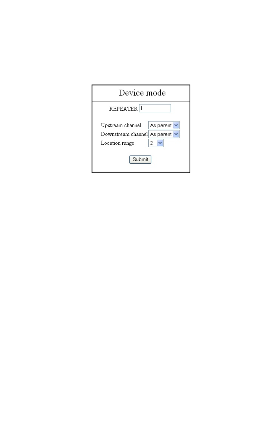
Repeater Details
The device mode entry page hardware type, followed by the modifiable device mode name
(defaults 1->32).
Upstream channel/Downstream channel:
(Repeater only) Used to determine the RF channel of the Repeater, selected via drop
down menu (1 -> 16) and As parent Allows a Repeater to use the same RF channel as its
parent device. The default mode of operation, this allows for a self-organising radio
network.
Location range:
Defines the range of the location signal from the Repeater. The default value is ‘2’ which
gives an approximate range in indoor environments of 3m. A value of ‘1’ gives the shortest
range and ‘10’ the longest range. The range should not be set to high values in
deployments where location signal penetration through walls and floors is not desired.
Submit:
Submit the requested configuration.
9261-8173 Issue 2 Page 40
© 2007 Multitone Electronics PLC
EkoTek System Installation and Configuration Manual Browser Interface
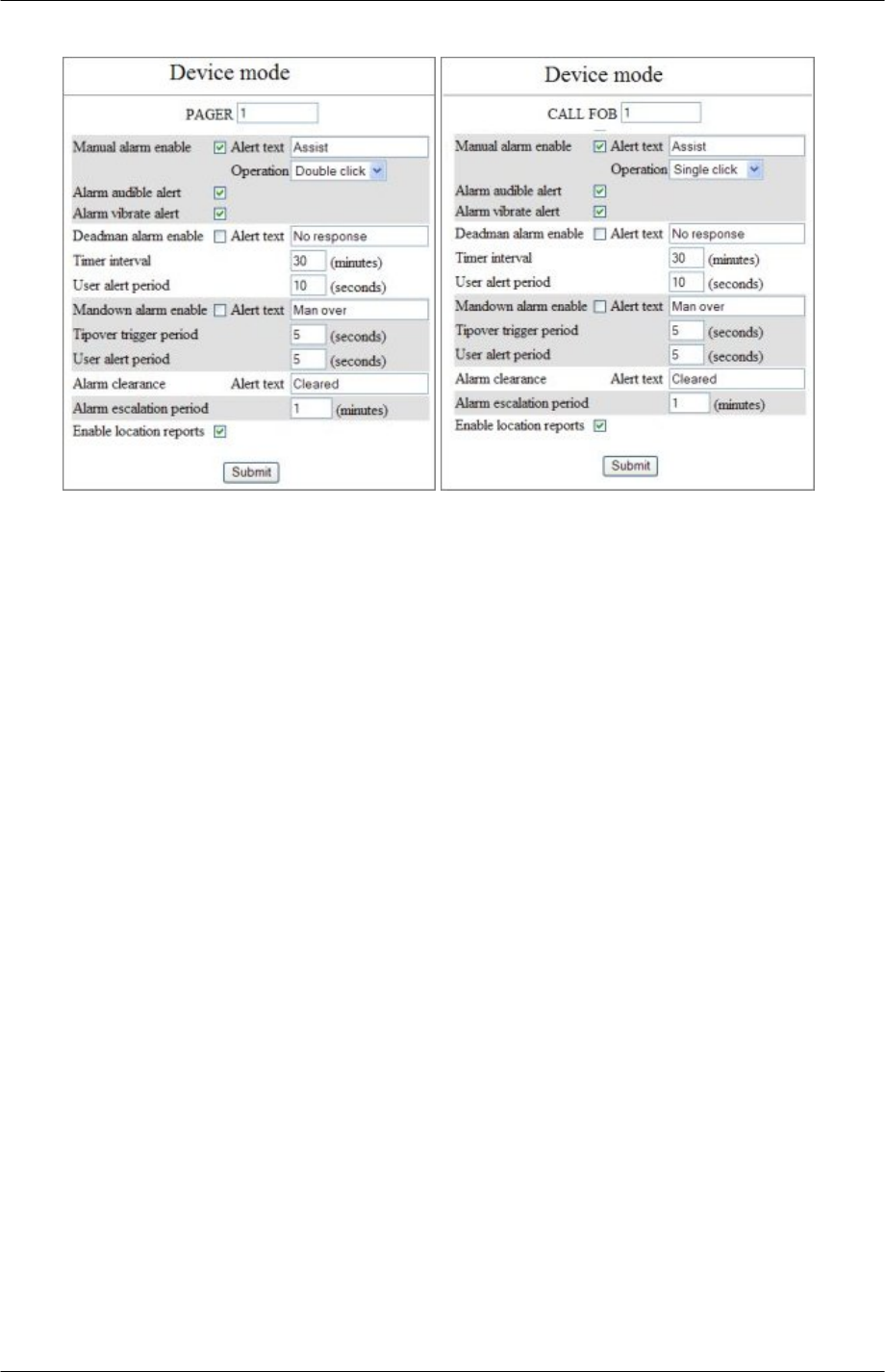
Pager and Fob Details
The device mode entry page content for the Pager and the Fob are the same. The
hardware type is followed by the modifiable device mode name (defaults 1->32).
Manual alarm enable:
Sets the device to raise manual alarms, i.e. via button press(es)
Alert text:
Modifiable text appears in the message sent to pagers when this alarm is activated.
Defaults to: Assist
9261-8173 Issue 2 Page 41
© 2007 Multitone Electronics PLC

EkoTek System Installation and Configuration Manual Browser Interface
Operation:
Define how many button presses are required to trigger the manual alarm (one or
two) selected by drop-down menu. Single click, Double click.
Alarm audible alert:
Define whether device buzzer sounds when manual alarm is raised.
Alarm vibrate alert:
Define whether the vibrate motor is activated when a manual alarm is raised.
Deadman alarm enable:
Enable the deadman automatic alarm. This is raised if input is not received from the User,
when prompted by the device.
Alert text:
Modifiable text appears in the message sent to Pagers, when this alarm is activated.
Defaults to: No response.
Timer interval:
Time between user input prompts (minutes).
User alert period:
Time that the buzzer prompt sounds on the device without user input, before the
alarm is raised (seconds).
Mandown alarm enable:
Enable the tip over switch automatic alarm; will raise an alarm if the unit has been moved
away from an upright position for a defined period of time.
Alert text:
Modifiable text appears in the message sent to pagers when this alarm is activated.
Defaults to: Man over.
Tipover trigger period:
Length of time a device must be moved away from upright, until the User warning
buzzer sounds (seconds).
User alert period:
Length of time that the buzzer sounds on the device, without it being returned to the
upright position and the cancel button pressed, before the alarm is raised (seconds).
Alarm clearance - Alert text:
Sets the text to appear in the message sent to Pagers, when any alarm for this device is
cleared. Defaults to: Cleared.
Alarm escalation period:
If an active alarm is not cleared within this period of time, then the device re-sends the
alarm with a raised escalation level (minutes).
Enable location reports:
If selected, then the ‘locate mobile device’ page will display the last known location of this
device.
Submit:
Submit the requested configuration.
Pager groups
These pages are used to manage Hubs and display Pagers into groups. Devices may
appear in none, one or many Pager groups. Each group is restricted to thirty-five devices.
9261-8173 Issue 2 Page 42
© 2007 Multitone Electronics PLC
EkoTek System Installation and Configuration Manual Browser Interface
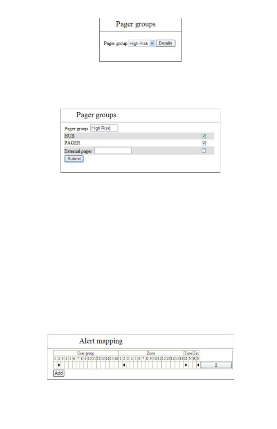
Pager group selection page
The list of 32 Pager groups is given in a drop-down menu (by default 1 - 32). Each group
can be assigned a name if required, using the Pager Group entry page.
Click ‘Details’ to open the Pager Group entry page and set up a group.
Pager group entry page
Pager group
Enter text for the Pager Group name.
All the connected display equipped devices are listed (by name) and a checkbox denoting
membership to this group. Check the box to add the devices to the group.
External pager
If connection is to be made to an external Pager, enter the Pager identifier into the number
field for, this the identifier sent via the TAP output interface. Check the box to add the
external Pager to the group.
Submit
Submit the new Pager group membership.
Note: - if more than 35 devices are selected, the changes will not be executed and the
Pager group will revert to it's saved settings.
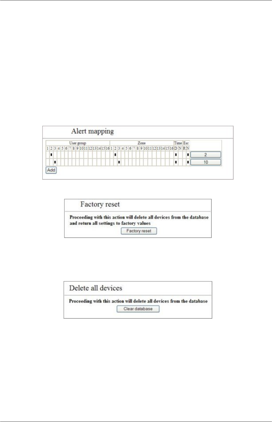
Alert rules
Alert rules manage the target Pager groups for alarms raised and enables all those alarms
raised in different zones and by devices assigned to specified user groups, to be directed
to particular Pager groups. Alarms with raised and normal escalations and at different
times of day, can be similarly routed. The page operates in a number of modes, displaying
the current rules table, allowing new rules to be added and existing rules to be modified
and deleted.
9261-8173 Issue 2 Page 43
© 2007 Multitone Electronics PLC
EkoTek System Installation and Configuration Manual Browser Interface
If any rules have been entered a table is displayed, the top row of which contains: -
User group: Parameters set in the device entry. Groups 1 to 16.
Zone: Parameters set in the device entry. Zones 1 to 16.
Time: The day/night setting of the system. D =Day, N= Night.
Esc: The escalation level of the alarm. R = Raised, N=Normal.
A black square means that a particular group/zone/time of day/escalation has been
included in the rule). The end of the row is a button containing the name of the Pager
group that is targeted by the rule. If there are more than 16 rules in the table, the header
will be repeated after the last rule.
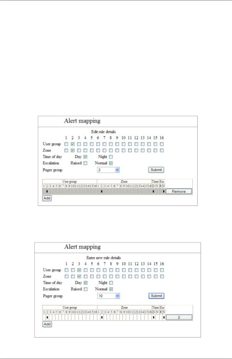
Edit mapping.
Clicking the Pager group name button at the end of the row causes the page to be re-
loaded with modifiable rules; the selected rule will appear as a shaded row and in place of
the Pager group name a remove button appears. The checkboxes are pre-loaded with the
current rules settings. Change the rule settings as required and then click submit to save
the amendments.
Remove
Clicking the ‘Remove’ button will remove that rule from the table.
Add
Click the ‘Add’ button to enter a brand new rule: note that this will only appear if there are
currently fewer than 32 rules.
Clicking the Add button will present a screen very similar to the edit rule mode; the initial
line is Enter new rules details followed by the options and (clear) checkboxes as for
9261-8173 Issue 2 Page 44
© 2007 Multitone Electronics PLC
EkoTek System Installation and Configuration Manual Browser Interface
the edit. No rule table entry is shaded. Pressing submit will cause a conflict check, as
with the edit rule function.
User group: Select the user group(s) using the rule.
Zone: Select the zone(s) using the rule.
Time of day: Select the day and/or night settings of the system.
Escalation: The escalation level of the alarm. R = Raised, N=Normal
Pager Group: Select a pager group.
Submit: The submission of the rule will cause a check for rule conflicts: any
specified alarm event must only result in a single pager group target. If a conflict is
detected the change is not made, the edit rules detail table will remain on the page
(with the requested new settings) in order to enable the conflict to be resolved.
After a successful submission the Alert Mapping page shows the new rule
added to the list.
Factory reset
Click ‘Factory Reset’ button to return network to factory settings (all devices deleted, IP
addresses reset etc). The following text appears: ‘Proceeding with this action will delete all
devices from the database and return all settings to factory values’.
Delete all devices
Click the ‘Clear database’ button to clear the database of all network devices, but leave
passwords, IP addresses etc. as set.
The following text appears: ‘Proceeding with this action will delete all devices from the
database’.
9261-8173 Issue 2 Page 45
© 2007 Multitone Electronics PLC
EkoTek System Installation and Configuration Manual Browser Interface
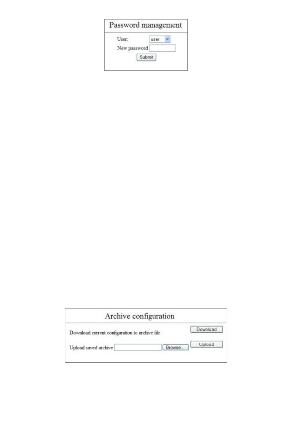
Passwords
Change the system passwords.
User name followed by a drop-down menu containing: -
User
The User level allows access to all pages within the Main and Maintenance menus
and to the passwords page under the Configuration menu (it can only change the
password for the user).
Admin
Admin level allows access all functions.
New password
Enter new password in the text input box.
Submit
Submit the new password.
The following text will be displayed according to the outcome
‘user/admin password changed’ or ’password change failed’
A password change failure may also be accompanied by the following
‘New password must be between 4 and 8 characters long’
If the web user is logged in as User and is attempting to change the admin password.
‘You do not have permission to change this password’ is displayed.
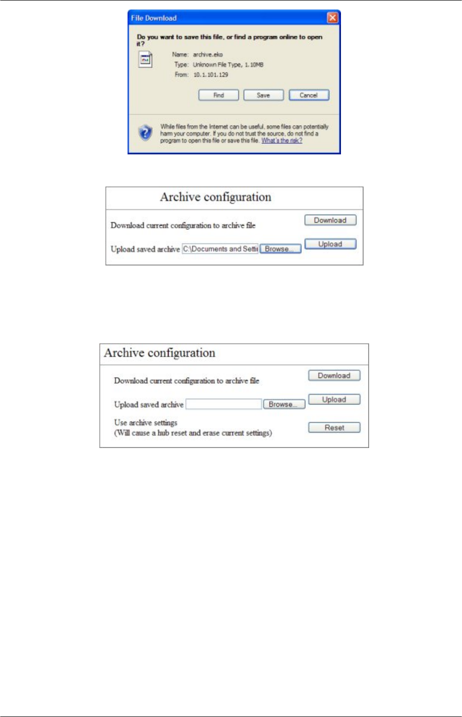
Archive
This page is used to manage archiving and restore system configuration.
Download current configuration to archive file
1. Click the Download button.
2. In the “File download” pop-up box, click save and save the file to a location on the
PC.
9261-8173 Issue 2 Page 46
© 2007 Multitone Electronics PLC
EkoTek System Installation and Configuration Manual Browser Interface
Upload saved archive
1. Click the ‘browse’ button and locate the saved archive.
2. Click the ‘upload’ button and the configuration from the selected file is transferred to
the Hub. This may take a few minutes. If there is a failure to upload a saved
configuration, this will result in the display of the following message: ‘Error
encountered uploading requested file’.
3. If a valid configuration has been uploaded to the Hub, the following lines are
displayed: ‘Use archive settings (Will cause a hub reset and erase current
settings)’.
4. Click the reset button to reset the Hub to the archived settings.
9261-8173 Issue 2 Page 47
© 2007 Multitone Electronics PLC
EkoTek System Installation and Configuration Manual
Final Checks
Connect a PC to the Hub over the Ethernet connection.
Open the device status in the maintenance menu.
Check that all the Repeaters are seen by the Hub. If a Repeater is not seen it may be:
• Out of reach of a parent
• Faulty
• Or the battery may be flat or disconnected.
Investigate cause using a survey pager. In cases where it is too far from the nearest
Repeater to get a viable link, then a Repeater may be needed to infill and complete the
mesh.
Click the details for each Repeater and check the strength and quality of the link. If the link
looks marginal, remove the parent of that Repeater from the network and see if it will sign
on to a different parent with a better link.
Register a Pager and a Fob on the system in the same paging group and see if an alarm
from the Fob is received at the Pager and that the response is sent to the Fob on the
network.
This completes the installation.
9261-8173 Issue 2 Page 48
© 2007 Multitone Electronics PLC

EkoTek System Installation and Configuration Manual
Appendices
Appendix 1: Miscellaneous system messages
The following on-system messages are generated in addition to the web-server interface.
Personal security messages
Accepted
Generated as a consequence of a Pager accepting a raised alarm.
Pager response messages
Delivered
Accepted
Rejected
Denoting the delivery acknowledgement and appropriate User acceptance/rejection.
Maintenance messages
LOW battery
Generated when the battery level drops to 20%, will be re-generated for every further 3%
drop until
REPLACE battery
Is generated at 5% battery level and re-generated for every further drop.
If a fixed device fails to report its status as scheduled on 4 consecutive occasions (each
report sent at 4.5 hour intervals) and if the device remains persistently not reporting its
status (i.e. a further 6 consecutive missed status reports), the following message is
generated:
Maintenance required
Generated when maintenance is required.
9261-8173 Issue 2 Page 49
© 2007 Multitone Electronics PLC

EkoTek System Installation and Configuration Manual
Appendix 2 Specifications
Specifications
Radio Frequency 2405 – 2480 MHz
Radio Channels 16
Channel Operating Mode Fixed frequency, or frequency hopping
Radio channels simultaneously used
per system Max 16
Radio Power 10mW
Radio Coding CDMA IEEE 802.15.4
Hub Power AC-DC Power Adaptor
Hub Backup Batteries 3 x `C´ cell NiMH rechargeable batteries
Repeater Power 2 x `D´ cell High Capacity Alkaline Manganese
batteries
Pager Power 1 x `AAA´ cell High Capacity Alkaline
Manganese, or NiMH rechargeable battery
Call Fob Power 1 x `AAA´ cell High Capacity Alkaline
Manganese, or NiMH rechargeable battery
Max. number of Repeaters per radio
channels Max. 90
Max. number of Pagers Max. 127
Number of Pagers in a Pager group Max. 35
Max. number of devices per system Max. 500
9261-8173 Issue 2 Page 50
© 2007 Multitone Electronics PLC

EkoTek System Installation and Configuration Manual
Appendix 3 RS232 Cable Pin outs for connecting Modem to
the Hub
DB25 DCE DB9
2 TXD 3 Transmitted Data
3 RXD 2 Received Data
4 RTS 7 Request to Send
5 CTS 8 Clear to Send
6** DSR 6 Data Set Ready
7 GND 5 Signal Ground
8 CD 1 Rec. Line Signal Detector
Link
** = not connected
9261-8173 Issue 2 Page 51
© 2007 Multitone Electronics PLC

Related Documentation and Revision History
Revision History
Issue Date Author Revision
1 June 2007 M Windett Initial Document.
2 30.08.07 R.Robertson Production Issue
Related Documentation
Title Part Number
EkoTek Pager User Guide 9261-8275
EkoTek Hub User Guide 9261-8276
EkoTek Call Fob User Guide 9261-8277
EkoTek Fob Quick Instructions 9261-8311
EkoTek Pager Quick Instructions 9261-8312
EkoTek Hub Help Files (HTML) 4761-8313

Multitone Electronics plc
Multitone House,
Shortwood Copse Lane,
Basingstoke,
Hampshire,
England RG23 7DH
9261-8173 Issue 2