Multitone Electronics PLC RPT503 UHF Paging Transmitter User Manual Installation Guide
Multitone Electronics PLC UHF Paging Transmitter Installation Guide
UserManual.wiki
>
Multitone Electronics PLC
>
RPT503 User Manual
>
Installation Guide
Contents
1.
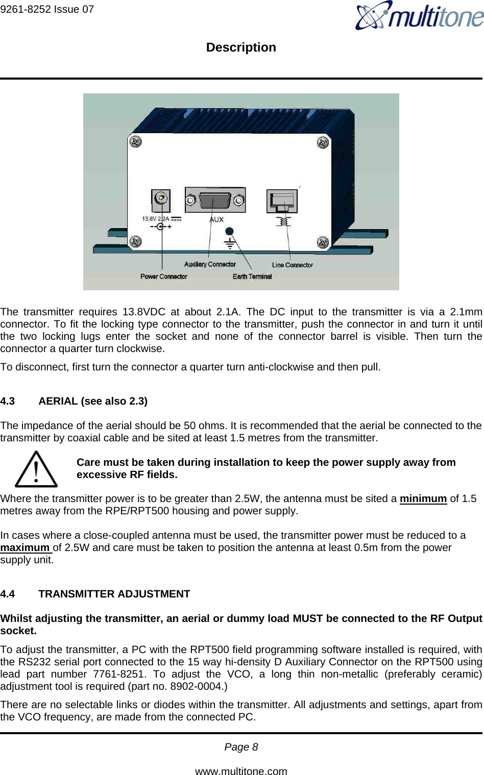
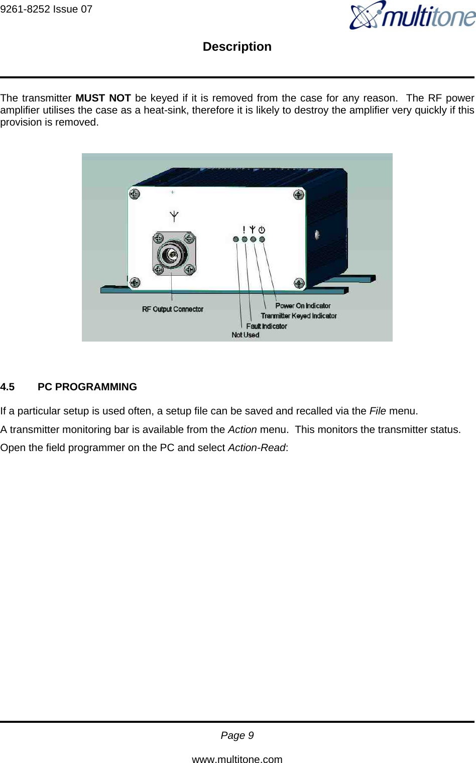
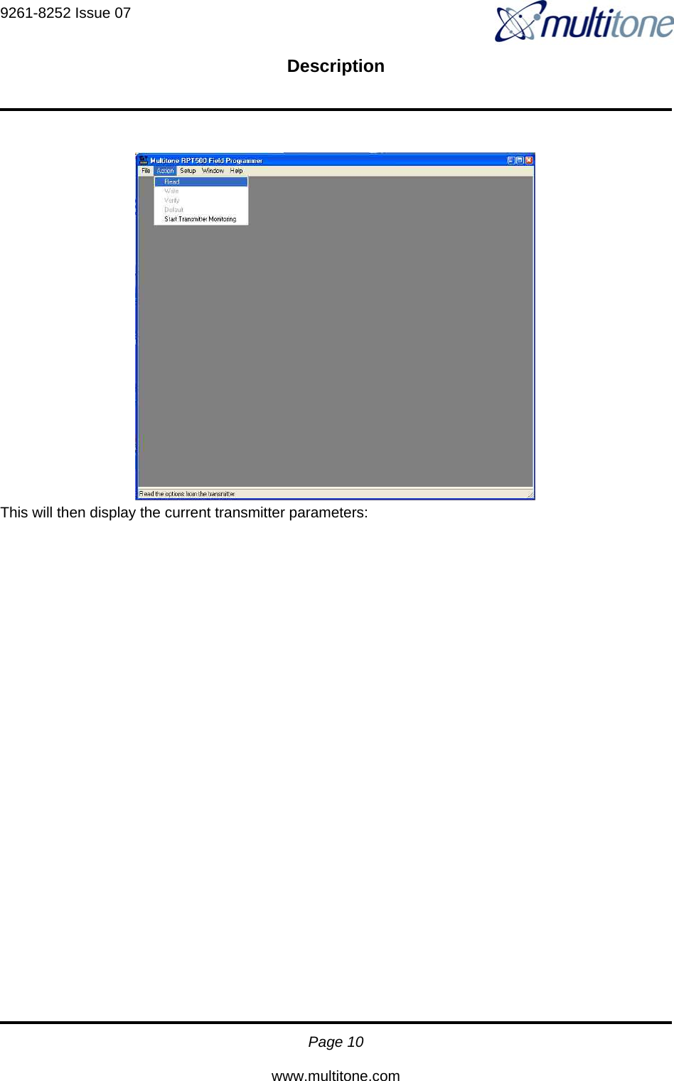
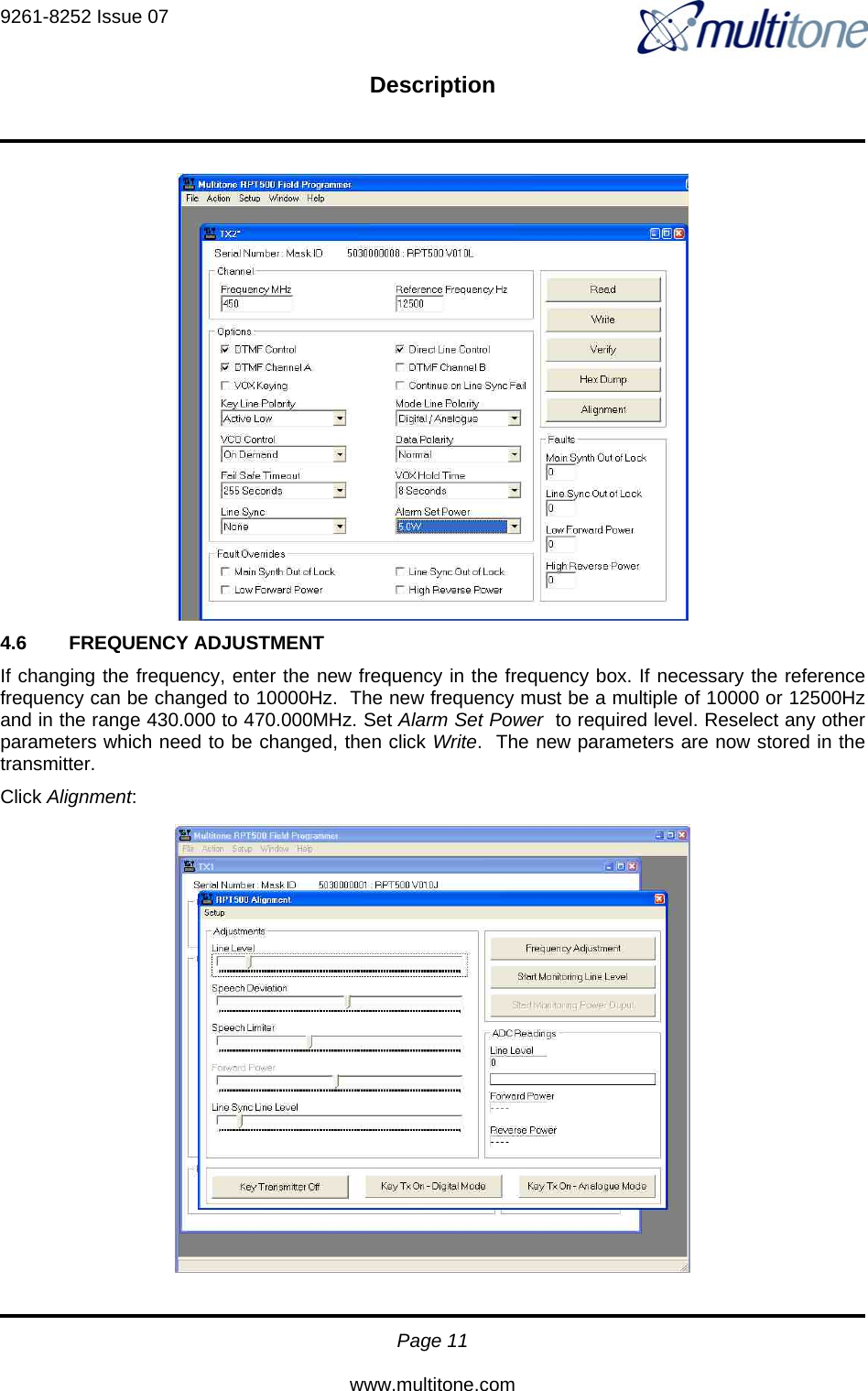
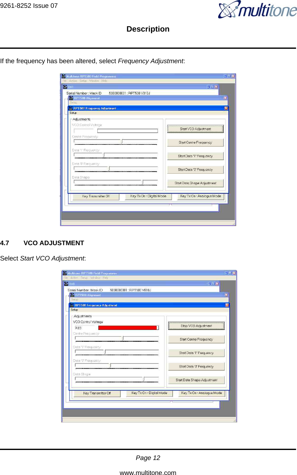
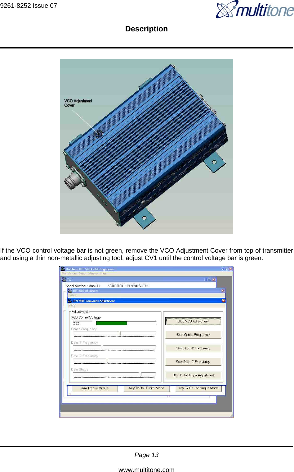
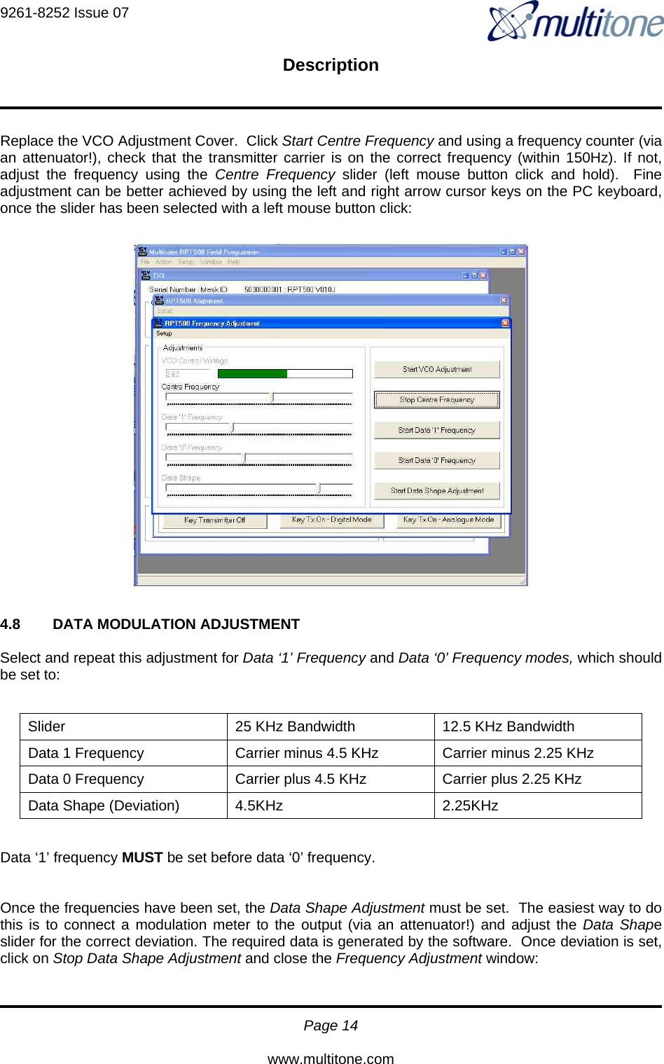
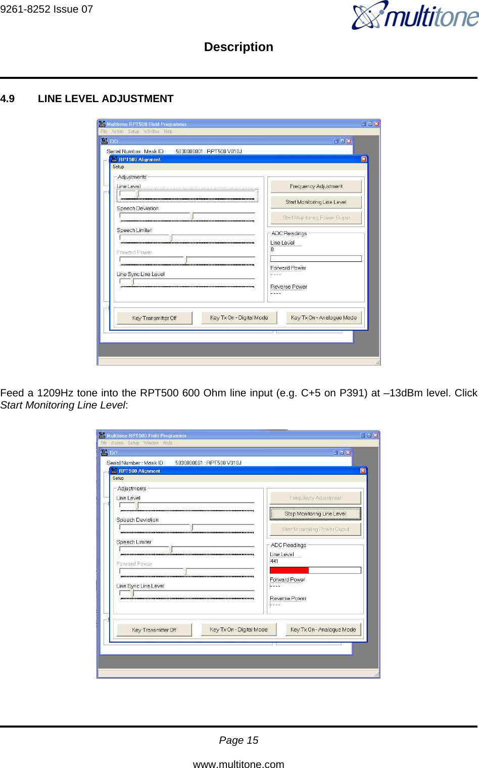
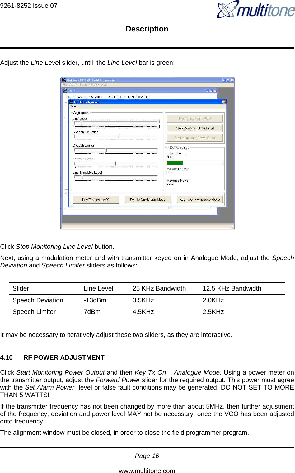
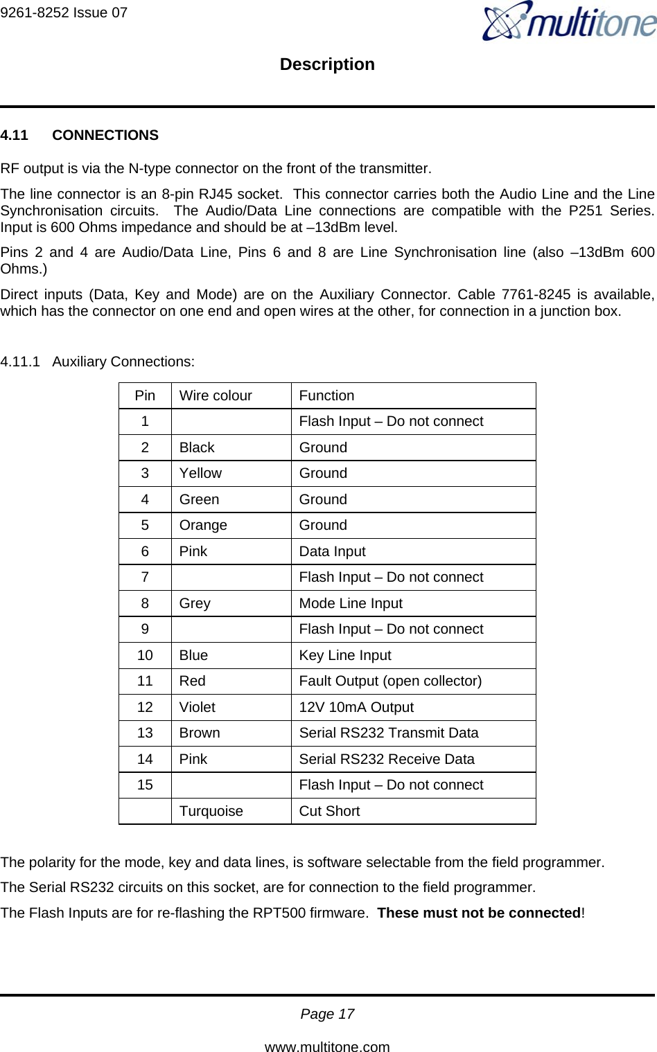
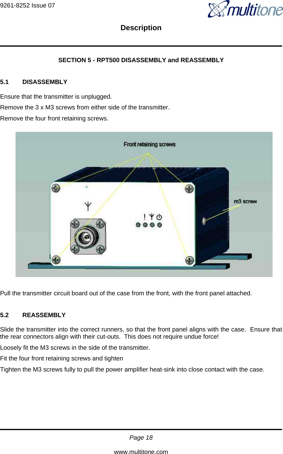
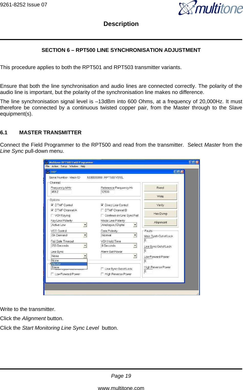
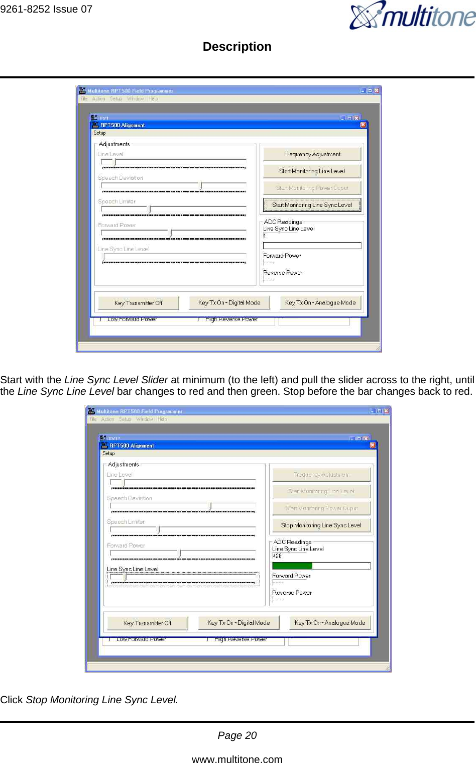
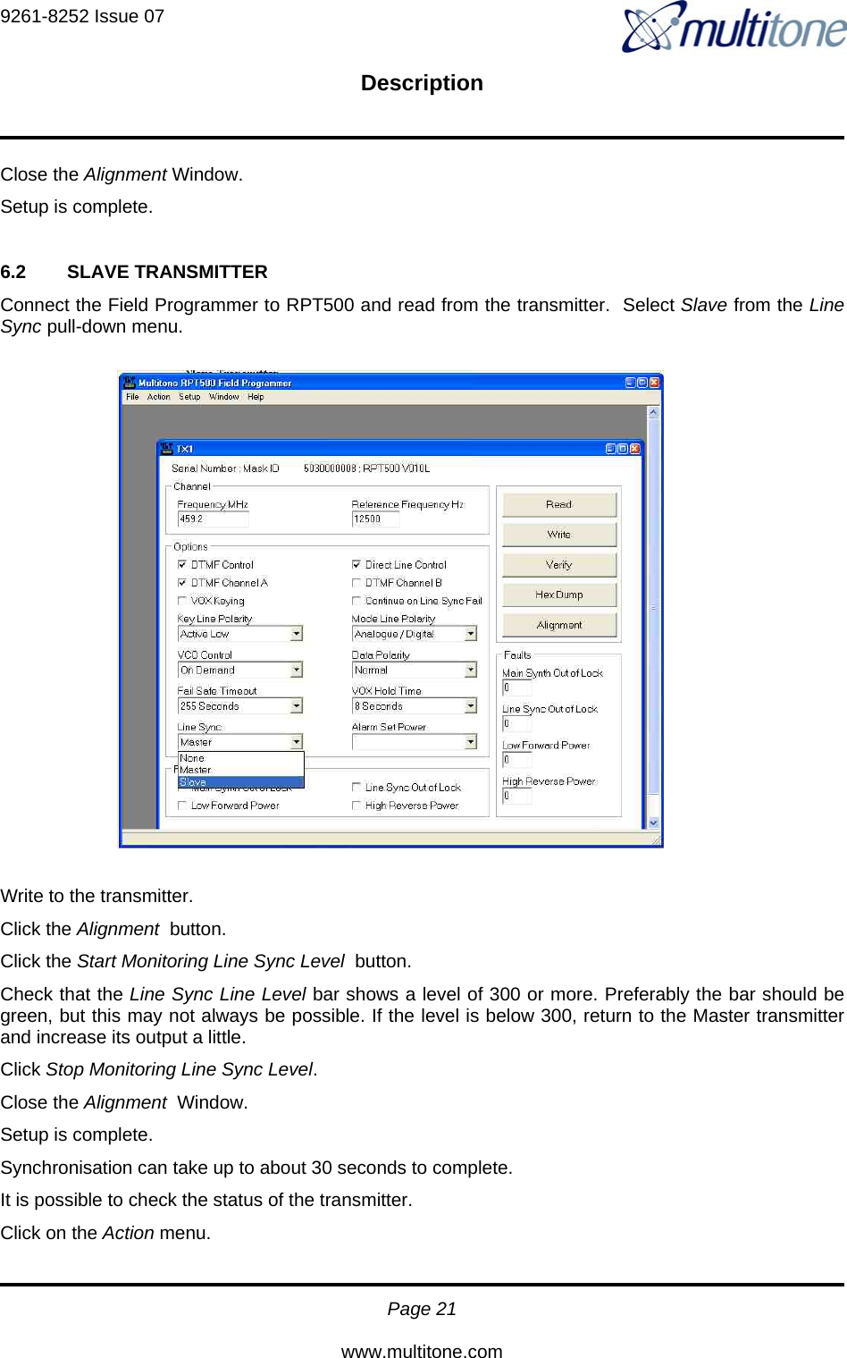
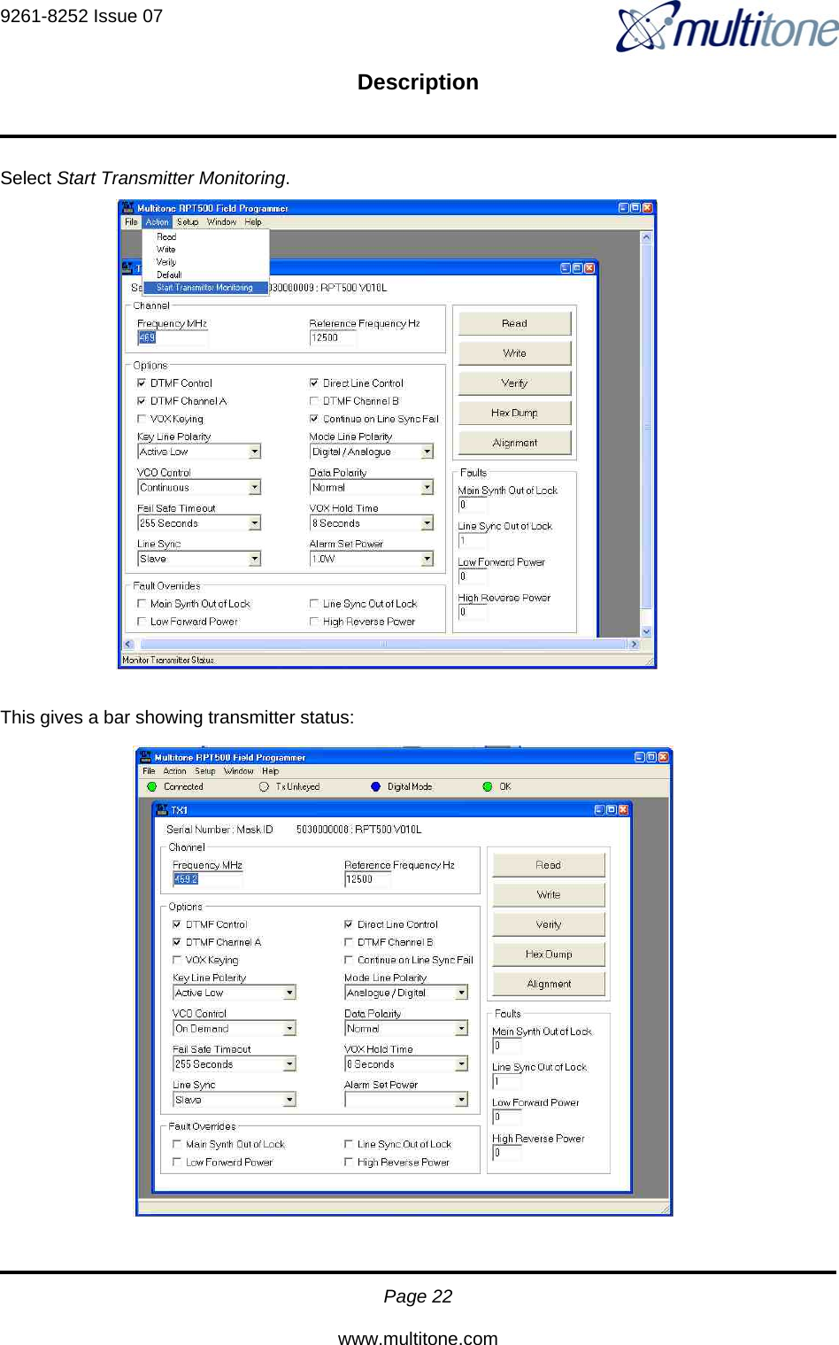
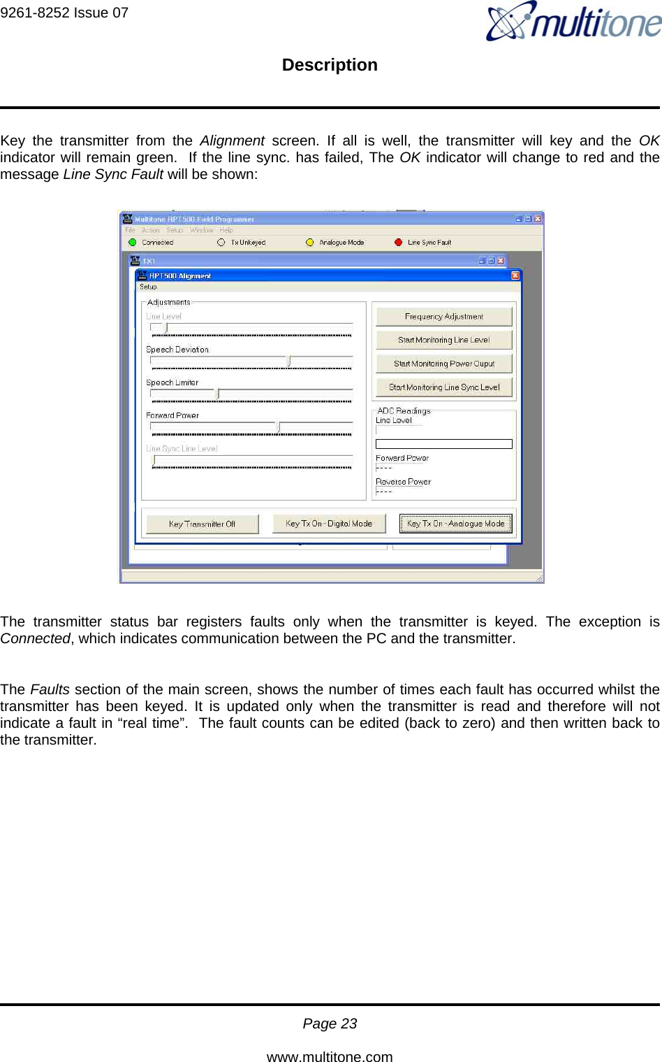
Installation Guide
2.
Product Data Sheet
Installation Guide
Navigation menu
Upload a User Manual
Namespaces
Wiki Guide
HTML
PDF
Info
Views
User Manual
Discussion / Help
Navigation