Mun Ah Plastic Electronic Toys MTM27HP RC Toy Transmitter User Manual CTX 2710 Manual op01
Mun Ah Plastic Electronic Toys Co., LTD. RC Toy Transmitter CTX 2710 Manual op01
user manual
2
SAFETY PRECAUTIONS
SAFETY PRECAUTIONS
THIS MODEL IS ONLY SUITABLE FOR PEOPLE 14 YEARS OLD AND UP.
THIS RADIO CONTROL MODEL IS NOT A TOY.
Introduction
Safety, Precautions, and Warnings
Beginner should seek advice from experienced person in order to assemble the model or parts correctly and to make best performance.
* Assemble this model or parts only in place out of children’s reach, and take safe precautions before operating this model. User is fully responsible for the model assembly and
safe operations.
This is a sophisticated hobby product and not a toy. It must be operated with caution and common sense. User also requires some basic mechanical abilities. Fail to operate this
product in a safe and responsible manner could result in injury or do damage to the product or other properties. This product is not intended for use by children without direct adult
supervision. The product manual contains instructions for safe operation and maintenance. It is essential to read and follow all the instructions and warnings in the manual prior to
assembly, setup or use, in order to operate correctly and avoid damage or injury.
As the user of this product, you are solely responsible for operating it in a manner that does not endanger youself and others or result in damage to the product or the property
of others.
This model is controlled by a radio signal that is subject to interference from many sources outside your control. This interference can cause momentary loss of control so it is
necessary to always keep a safe distance in all directions around your model, as this will help to avoid collisions or injury.
• Always operate your model in an open area away from cars, traffic, or people.
• Avoid operating your model on the street where injury or damage can occur.
• Never operate the model out into the street or populated areas for any reason.
• Never operate your model with low transmitter batteries.
• Carefully follow the directions and warnings for this product and any optional support
equipments (chargers, rechargeable battery packs, etc.) that you use.
• Keep all chemicals, small parts and anything electrical out of the reach of children.
• Moisture causes damage to electronics. Avoid water exposure to all equipments not
specifically designed and protected for this purpose.
The associated regulatory agencies of the following countries recognize the noted certifications for this product as authorized for sale and use.
UK
FI
CZ
AT
NL FR
DE
EE
SK
IT LU
DK
LV
HUES
MT
BG
LT
RO PT
CY
SE
PL SI IEGR
CE Compliance Information For The European Union
Declaration of Conformity
Products: Carisma CTX-2710 2.4GHz Transmitter, MRX2800 Receiver
Equipment Class: 2
The objects of declaration described above are in conformity with the requirements of the specifications listed below.
Manufactured By : Mun Ah Plastic Electronic Toys Company.,Ltd
Statement - This device complies with Part 15 of the FCC Rules.
Operation is subject to the following two conditions:
(1) this device may not cause harmful interference, and
(2) this device must accept any interference received, including interference that may cause undesired operation.
Changes or modifications not expressly approved by the party responsible for compliance could void the user’s authority to operate the equipment.
FCC ID YDTMTM27HP
RF Exposure Warning:
This equipment complies with FCC radiation exposure limits set forth for an uncontrolled environment.
And should be operated with minimum distance of 20 cm between the antenna & your body.
Item Name : Carisma CTX-2710 2.4GHz Transmitter and MRX2800 Receiver
ETSI EN 300 328 V1.7.1:2006
ETSI EN 301 489-1 V1.8.1:2008
EN 301 489-17 V2.1.1:2009
EN 50371:2002
Directive 1999/5/EC (R&TTE)
Article 3.1a Health
Article 3.1b EMC
Article 3.2 Radio Spectrum
ST.TRIM
TH.TRIM
4
ABOUT THE RADIO SYSTEM
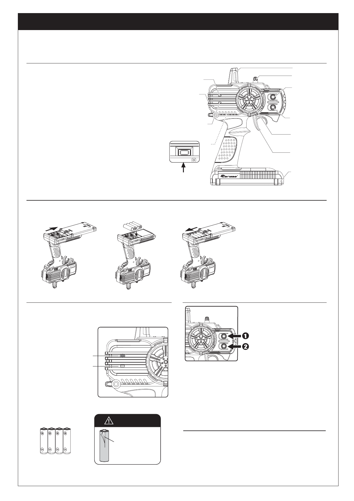
CTX-2710
Battery
Compartment Tray
Steering Trim Dial
Dual Rate Dial
* In general, user will experience under steer when making a wide turn at
high speed or over steer when making sharp turn at high speed (easy to
spin out). User should practice the throttle and steering approach for
different cornering at different speed or road surface.
Battery Installation
SYNC
The following is an overview of the various functions and adjustments found on CTX-2710 radio system for Carisma models. It is important to read and understand about all of these
functions and adjustments before driving.
Carisma CTX-2710 2.4GHz FHSS Technology System
Power ON / OFF the Transmitter
ST.TRIM
TH.TRIM
The Transmitter CTX-2710
Steering Wheel : Control direction (Left / Right) of the RC model.
Throttle Trigger : Control speed and direction (Forward/Brake/Backward)
of the driving model.
Antenna : Transmit signal to the model.
Power ON / OFF : Power ON / OFF the transmitter
SYNC & Battery Indicator : Top Green LED light indicates synchronization status
and/or adequate battery power supply.
Power Indicator : Bottom Red LED light indicates power “ON”.
Dual Rate Dial : Adjust the same maximum steering angle on both sides
when model turns Left / Right
ST. Trim Dial : Adjust the neutral position of steering servo when model
wheels are straight ahead.
TH. Trim Dial : Make sure the model stays still when releasing the
throttle trigger.
Battery Compartment Tray : Cover and hold the batteries powering the transmitter.
Supplied with 4 x 1.5V AA Batteries,
CTX-2710 can be operated a few hours.
Installation: Remove the battery
compartment cover as shown below.
Install the batteries observing
the polarity marked on battery
compartment.
Then reinstall the battery
compartment cover as the
Picture shown below.
Warning : Never disassemble batteries or
put the batteries in fire, chemical agents,
otherwise they may cause personal injuries
or property damages.
Battery Disposal : Observe corresponding
regulations about wasted battery treatment
regulations.
1. After running out of power, dispose of
wasted batteries in designated areas far
away from water supply, household areas
and planted areas.
2. Submit the wasted batteries to specific
recycling stations.
Battery LED Indicator
The Green LED indicator located on the front left side of the transmitter indicates the
power supply of batteries. The green LED will go solid on indicating that the batteries
have sufficient power. When batteries voltage drops below 4 volts, the Green LED will
flash, indicating the batteries power is low and should be replaced.
Pre-Run Check
Solid Green :
Sufficient Power supply
Flashing :
Time to replace batteries
Steering Wheel
Throttle Trigger
Throttle Trim Dial
Antenna
SYNC and
Battery
Level Indicator
Power Indicator
Power
ON / OFF
Green
Red
SYNC
SYNC Button
(Synchronization)
* Always turn on the transmitter first by sliding the switch on the left side
from bottom to top. The small red and green lights above the switch should
both light up. If not, you need to check for low or incorrectly installed
batteries.
1. Steering : Adjust the steering trim to
keep the front wheels in straight line
when steering wheel remains in
NEUTRAL position.
2. Throttle : Adjust the throttle trim to
ensure the rear wheels stop rotating
when throttle trigger remains in
NEUTRAL position.
For Transmitter
Damages or Leaking
Do not use any damaged
batteries.
x 4
This product must never be thrown away with other waste. Thus the users are liable
for disposing the wasted model by submitting them to designated collection stations
specific for recycling electronic and electric items. Disposing of the wasted model in
this way is helpful to conserve natural resources and enable to keep human health
and protect the environment. For more information about wasted model disposal and
recycling, please contact your local city office, your disposal service or where you
purchased the product.
Instructions for Disposal of WEEE by
Users in the European Union
Heavy Duty
1.5V “AA” Size Batteries
ATTENTION
SYNC
5
ABOUT THE RADIO SYSTEM
RECEIVER CONNECTION AND INSTALLATION
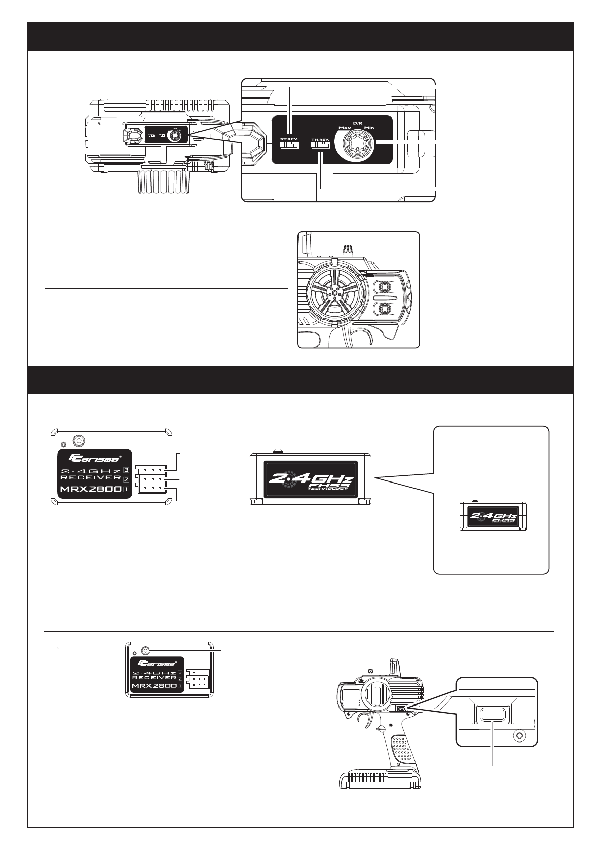
Top Control Panel
Steering Reverse Switch
Dual Rate Dial
Throttle Reverse Switch
Reversing
Reversing is used to change the response direction of steering wheel and throttle trigger.
CTX-2710 Transmitter features 2 reversing functions: Steering Reverse and Throttle Reverse.
Steering Reverse: Reverse the response direction when operating steering wheel.
Turning left steering wheel, the model turns right while turning right the model turns left.
Throttle Reverse: Reverse the response direction when operating throttle trigger.
Pushing forward throttle trigger the model moves backward while pulling back, the
model moves forward. If necessary you can just use a small screwdriver to adjust the
orresponding switches.
CTX-2710 features two trimming functions:
Steering Trim and Throttle Trim.
Steering Trim Dial :
Adjust the neutral position of steering servo
when the wheels are straight ahead.
Normally steering trim is adjusted until the
model can keep straight tracks.
Throttle Trim Dial :
Adjust neutral position of throttle servo. Make
sure the model stays still when releasing the
throttle trigger.
Trimming
Dual Rate Dial enables to adjust the same maximum steering angle of servo on both
sides (Left and Right) when model makes steering. The Dual Rate Dial affects the
sensitivity of servo. Reducing dual rate value can lower the sensitivity of servo and
reduce the same maximum steering angle on both sides. Remember to adjust the
dual rate value within the adjustment range.
Dual Rate Dial
1. Prior to any operation make sure the transmitter and receiver are both turned off.
2. Press and hold the setup button on the receiver while power on the receiver.
3. Release the setup button till green LED flashes.
4. Press the setup button to select the frame rate with green LED flashing.
Faster Flashing = High frame rate (7ms) for digital servo
Slower Flashing = Low frame rate (15ms)for analogue servo
5. Power on the transmitter. With the transmitter steering wheel and throttle trigger
in neutral position (full stop and straight steering), press the SYNC button of the
transmitter.
6. When synchronization is done, the green LED on both receiver and transmitter
will turn solid on.
Synchronization & Frame Rate Adjust
Setup Key of Receiver
Carisma 2.4GHz Receiver MRX2800
Remarks :
The mounting positions of receiver
and antenna cable greatly affect the
operating range.
Install the antenna vertically to
the ground.
Auxiliary Port (Reserved)
Steering Port : Where to plug in the servos.
Throttle Port : Where to plug in the Electronic
Speed Controler (ESC).
Setup button : Synchronize transmitter and receiver.
Select frame rate.
Steering Port
Throttle Port
Auxiliary Port
(Reserved)
Warning :
• Never bend the metal pins on the PCB of receiver.
• Never cut the antenna cable.
• Install the antenna vertically as shown in the figure.
• Keep the antenna as far away from the motor, ESC
and other noise sources as you possibly can.
Setup Button
Antenna Cable
MRX2800
Tips :
• Wrap the receiver with something soft, such as foam
rubber, to avoid vibration. If there is a chance of getting
wet, put the receiver in a waterproof bag or balloon.
ST.TRIM
TH.TRIM
Synchronization Button
7
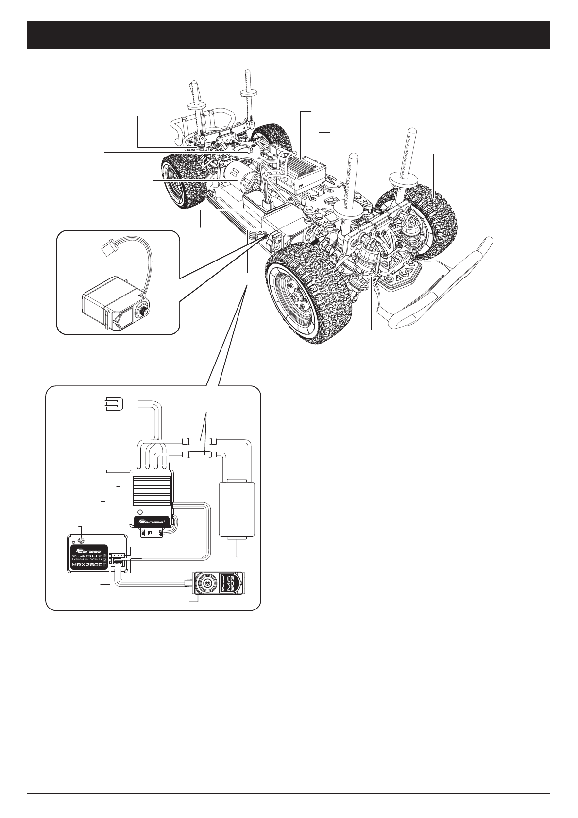
ABOUT THE CHASSIS
370 Motor
Rear
Oil Shock
Unit
Adjustable
Slipper
Battery Pack
Electronic Speed Controller
MSC-2000RB
Power Switch
Power Switch
Servo
MS-903GT
High Traction
Rubber Tire
Front
Oil Shock
Unit
2.4GHz
Receiver
MRX2800
2.4GHz Receiver
MRX2800
ESC MSC-2000RB Features
When ESC power on, LED will be flashing for 2 seconds to indicate the Selected Battery Type.
During LED flashing, user can press the key to select the other battery type.
After key pressed, LED will be flashing 2 more seconds.
1. Turn on ESC and push button once within 2 seconds, push again to select between
LiPo(7.4V)/ NiMH(7.2V).
2. Red light will be LiPo.
3. Green light will be NiMH.
Battery Selection:
Servo MS-903GT
Electronic Speed
Controller
MSC-2000RB
Battery Plug
Connector
Bullet Connector
Setup
Button
Steering Port
Throttle Port
Auxiliary Port(Reserve)
370 Motor
Step 1 - Turn on the transmitter, throttle at neutral ( stop ) position.
Step 2 - Hold the setup button on the ESC and switch on, the Red & Green LED will light up,
then release the setup button.
Step 3 - Green LED will flash, then hold the throttle to maximum forward position until the
Green LED becomes Solid on.
Step 4 - Wait until Red LED flashes, then hold the throttle to the maximum Reverse position
until the Red LED becomes Solid on.
Step 5 - Gently release the throttle to neutral ( stop ) position.
During normal operation, the GREEN LED is used to indicate the ESC mode in stop position
as following:
• Forward / Reverse Mode & Smart Brake Mode - GREEN LED solid on
• Forward Only Mode - GREEN LED fast flashing
When the ESC temperature is over the safety limit, ESC will shut off power output automatically,
meanwhile, Red & Green LED will flash alternatively for 30 secs.
After 30 secs, ESC normal function will be resumed.
When motor is stalled, ESC will shut off power output automatically, meanwhile, Red LED will
be flashing for 30 secs. After 30 secs, ESC will back to normal.
User can select either 6V cutoff for LiPo or 4V cutoff for NiMH. When input voltage is under
the set cut off limit, ESC will shut off power output automatically and protect battery effectively.
WARNING :
Do not modify connector plug or motor connector otherwise
may cause possible damage to MSC-2000RB ESC due to
improper use!
Do not run the model in rainy day or under terrible weather.
Under Voltage Protection ( NiMH / LiPo ) :
One touch End-Points Setup:
ESC Mode Selection:
Over Heat Protection:
Over Load Protection:
ST.TRIM
TH.TRIM
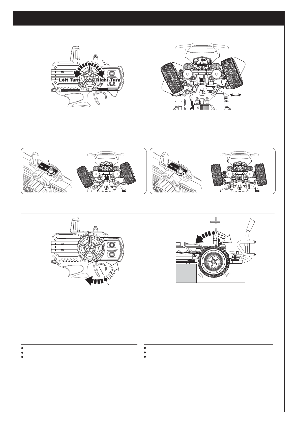
STEERING AND RATE ADJUSTMENT
8
ST.TRIM
TH.TRIM
Your transmitter is equipped with a steering rate control on the top of the transmitter just above the steering wheel. This advanced feature, usually found only on competition- type
transmitter, allows you to adjust the amount the front tires move when you turn the steering wheel. This is really helpful when you are on slick, as well as high traction,surfaces. If
your Carisma model turns too sharply and / or spins out easily, try turning the steering rate down by rotating the knob counterclockwise ( to the left ). For sharper or additional
steering, turn the knob clockwise ( to the right ).
To reverse, push the throttle trigger to the braking position. After the car has come to a stop, release the throttle trigger and pull the trigger again to go reverse.
Control of the R/C Model
Steering Rate
Throttle Trigger
Neutral Position (Stop)Neutral Position (Stop)
Reverse
Forward Reverse
Brake, Reverse
Always Never
Neutral
Forward
Forward
Forward
Once power on the Carisma model Car, turn on the transmitter by sliding the switch to "On"position. If the wheels turn, adjust the “TH Trim” knob located on the lower right
of the steering wheel until they stop. To go forward, pull the trigger back. If you need reverse, wait for the model to stop then push the trigger forward. When going forward,
the model should move in a straight line. If not, adjust the “ST Trim” so that it tracks in a straight line without having to move the steering wheel.
After you have finished, turn the Carisma model Car off first by sliding the switch on the ESC to the “ OFF” position. After the model has been turned off, turn off the transmitter.
If you wish to clean your Carisma model Car, use compressed air and / or a soft paint brush to remove the dust and dirt. Never use chemicals or anything wet as it can cause
damage to both the electronics and plastic parts.
Operate the Carisma model Car with low battery power
Run the Carisma model Car through water
Use chemicals to clean the chassis
Take caution when running your vehicle near people
Turn both the Carisma model car and the Transmitter “OFF” when done
Check the battery condition of the transmitter before running
Proportional
Steering
Proportional
Steering
Proportional
Steering
Proportional
Steering
More Turning AngleMore Turning Angle Less Turning AngleLess Turning Angle