Murata Electronics North America 2410M Modular 2.4 GHz Transceiver User Manual Integration Guide
Murata Electronics North America Modular 2.4 GHz Transceiver Integration Guide
Contents
- 1. Integration Guide
- 2. Users Manual Statements To Be Added to Manual
- 3. Updated Users Manual
Integration Guide

WIT2410
2.4GHz Spread Spectrum
Wireless Industrial Transceiver
Integration Guide
June 15, 1999
One Meca Wa
y
Norcross, Georgia 30093
www.digital-wireless.com
(770) 564-5540

Note: This device has not been authorized
as required by the rules of the Federal
Communications Commission. This device
is not, and may not be, offered for sale or
lease, or sold or leased, until authorization
is obtained.
About This Manual
This manual is designed to allow integration of the Digital Wireless Corporation WIT2410 OEM
module into complete products. Care has been taken to try and make sure all of the information
in this manual is accurate. However, specifications can change over time and Digital Wireless
cannot guarantee the accuracy of this information. If you have any questions on any information
in this manual, please contact Digital Wireless Technical Support at (770) 564-5540.
TABLE OF CONTENTS
1. INTRODUCTION..................................................................................................................................1
1.1 Why Spread Spectrum?.....................................................................................................................1
1.2 Frequency Hopping vs. Direct Sequence.........................................................................................2
2. RADIO OPERATION............................................................................................................................4
2.1. Synchronization and Registration ...................................................................................................4
2.2. Data Transmission...........................................................................................................................5
2.2.1. Point-to-Point ........................................................................................................................5
2.2.2. Point-to-Multipoint................................................................................................................6
2.2.3. TDMA Mode.........................................................................................................................6
2.2.4. CSMA Mode .........................................................................................................................8
2.2.5. Full Duplex Communication.................................................................................................8
2.2.6. Error-free Packet Transmission Using ARQ.........................................................................8
2.3. Modes of Operation.........................................................................................................................9
2.3.1. Control and Data Modes........................................................................................................9
2.3.2. Sleep Mode..........................................................................................................................10
2.3.3. Low Power Mode and Duty Cycling...................................................................................10
3. PROTOCOL MODES..........................................................................................................................11
3.1. Packet Formats..............................................................................................................................12
3.1.1. Data Packet..........................................................................................................................13
3.1.3. Connect Packet....................................................................................................................13
3.1.4. Disconnect Packet (base only, receive only)......................................................................13
4. MODEM INTERFACE........................................................................................................................14
4.1. Interfacing to 5 Volt Systems........................................................................................................15
5. MODEM COMMANDS......................................................................................................................16
5.1. Serial Commands ..........................................................................................................................16
5.2. Network Commands......................................................................................................................17
5.3. Protocol Commands......................................................................................................................19
5.4. Status Commands..........................................................................................................................21
5.5. Memory Commands......................................................................................................................22
5.6. Modem Command Summary........................................................................................................23
6. WIT2410 DEVELOPER’S KIT...........................................................................................................24
6.1. COM24..........................................................................................................................................24
6.2. Demonstration Procedure..............................................................................................................25
6.3. Troubleshooting ............................................................................................................................26
7. APPENDICES......................................................................................................................................28
7.1. Technical Specifications ...............................................................................................................28
7.1.1. Power Specifications ...........................................................................................................28
7.1.2. RF Specifications.................................................................................................................28
7.2.2. Mechanical Specifications...................................................................................................28
7.3. Serial Connector Pinouts...............................................................................................................29
7.4. Approved Antennas.......................................................................................................................29
7.5. Technical Support .........................................................................................................................29
7.6. Mechanical Drawing .....................................................................................................................30
7.7. Warranty........................................................................................................................................31
© 1999 Digital Wireless Corporation 16/15/99
1. INTRODUCTION
The WIT2410 radio transceiver provides reliable wireless connectivity for either
point-to-point or multipoint applications. Frequency hopping spread spectrum technology
ensures maximum resistance to noise and multipath fading and robustness in the presence of
interfering signals, while operation in the 2.4 GHz ISM band allows license-free use and
worldwide compliance. A simple serial interface supports asynchronous data up to 230400
bps. An on-board 3 KB buffer and an error-correcting over-the-air protocol provide smooth
data flow and simplify the task of integration with existing applications.
- Multipath fading impervious
frequency hopping technology
with 75 frequency channels
(2401-2475 MHz).
- Supports point-to-point or
multipoint applications.
- Meets FCC rules 15.247 and ETS
300.328 for worldwide license-
free operation.
- Superior range to 802.11 wireless
LAN devices.
- Transparent ARQ protocol
w/3KB buffer ensures data
integrity.
- Digital addressing supports up to
32 networks, with 62 remotes per
network.
- Low power 3.3v CMOS signals
- Simple serial interface handles both
data and control at up to 230400
bps.
- Fast acquisition typically locks to
hopping pattern in 5 seconds or less.
- Selectable 10 mW or 100 mW
transmit power.
- Support for diversity antenna.
- Built-in data scrambling reduces
possibility of eavesdropping.
- Nonvolatile memory stores
configuration when powered off.
- Smart power management features
for low current consumption.
- Dynamic TDMA slot assignment
that maximizes throughput.
1.1 Why Spread Spectrum?
The radio transmission channel is very hostile, corrupted by noise, path loss and
interfering transmissions from other radios. Even in a pure interference-free
environment, radio performance faces serious degradation through a phenomenon
known as multipath fading. Multipath fading results when two or more reflected rays of
the transmitted signal arrive at the receiving antenna with opposing phase, thereby
partially or completely canceling the desired signal. This is a problem particularly
prevalent in indoor installations. In the frequency domain, a multipath fade can be
described as a frequency-selective notch that shifts in location and intensity over time as
reflections change due to motion of the radio or objects within its range. At any given
time, multipath fades will typically occupy 1% - 2% of the 2.4 GHz band. This means
that from a probabilistic viewpoint, a conventional radio system faces a 1% - 2% chance
of signal impairment at any given time due to multipath.
© 1999 Digital Wireless Corporation 26/15/99
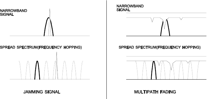
Spread spectrum reduces the vulnerability of a radio system to both interference from
jammers and multipath fading by distributing the transmitted signal over a larger region
of the frequency band than would otherwise be necessary to send the information. This
allows the signal to be reconstructed even though part of it may be lost or corrupted in
transit.
Figure 1
Narrowband vs. spread spectrum in the presence of interference
1.2 Frequency Hopping vs. Direct Sequence
The two primary approaches to spread spectrum are direct sequence (DS) and frequency
hopping (FH), either of which can generally be adapted to a given application. Direct
sequence spread spectrum is produced by multiplying the transmitted data stream by a
much faster, noise-like repeating pattern. The ratio by which this modulating pattern
exceeds the bit rate of the baseband data is called the processing gain, and is equal to the
amount of rejection the system affords against narrowband interference from multipath
and jammers. Transmitting the data signal as usual, but varying the carrier frequency
rapidly according to a pseudo-random pattern over a broad range of channels produces a
frequency hopping spectrum system.

© 1999 Digital Wireless Corporation 36/15/99
Figure 2
Forms of spread spectrum
One disadvantage of direct sequence systems is that due to spectrum constraints and the
design difficulties of broadband receivers, they generally employ only a minimal amount
of spreading (typically no more than the minimum required by the regulating agencies).
For this reason, the ability of DS systems to overcome fading and in-band jammers is
relatively weak. By contrast, FH systems are capable of probing the entire band if
necessary to find a channel free of interference. Essentially, this means that a FH
system will degrade gracefully as the channel gets noisier while a DS system may
exhibit uneven coverage or work well until a certain point and then give out completely.
Because it offers greater immunity to interfering signals, FH is often the preferred
choice for co-located systems. Since direct sequence signals are very wide, they tend to
offer few non-overlapping channels, whereas multiple hoppers may interleave with less
interference. Frequency hopping does carry some disadvantage in that as the transmitter
cycles through the hopping pattern it is nearly certain to visit a few blocked channels
where no data can be sent. If these channels are the same from trip to trip, they can be
memorized and avoided; unfortunately, this is generally not the case, as it may take
several seconds to completely cover the hop sequence during which time the multipath
delay profile may have changed substantially. To ensure seamless operation throughout
these outages, a hopping radio must be capable of buffering its data until a clear channel
can be found. A second consideration of frequency hopping systems is that they require
an initial acquisition period during which the receiver must lock on to the moving carrier
of the transmitter before any data can be sent, which typically takes several seconds. In
summary, frequency hopping systems generally feature greater coverage and channel
utilization than comparable direct sequence systems. Of course, other implementation
factors such as size, cost, power consumption and ease of implementation must also be
considered before a final radio design choice can be made.
As an additional benefit, RF spectrum has been set aside at 2.4 GHz in most countries
(including the U.S.) for the purpose of allowing compliant spread spectrum systems to
operate freely without the requirement of a site license. This regulatory convenience
alone has been a large motivation for the industry-wide move toward spread spectrum.
© 1999 Digital Wireless Corporation 46/15/99
2. RADIO OPERATION
2.1. Synchronization and Registration
As discussed above, frequency hopping radios periodically change the frequency at which
they transmit. In order for the other radios in the network to receive the transmission, they
must be listening to the frequency over which the current transmission is being sent. To do
this, all the radios in the net must be synchronized and must be set to the same hopping
pattern. All radios in a net must be set to the same hopping pattern before attempting to
communicate.
In point-to-point or point-to-multipoint arrangements, one radio module is designated as the
base station. All other radios are designated remotes. One of the responsibilities of the base
station is to transmit a synchronization signal to the remotes to allow them to synchronize
with the base station. Since the remotes know the hopping pattern, once they are
synchronized with the base station, they know which frequency to hop to and when. Every
time the base station hops to a different frequency, it immediately transmits a synchronizing
signal.
When a remote is powered on, it rapidly scans the frequency band for the synchronizing
signal. Since the base station is transmitting over 75 frequencies and the remote is scanning
75 frequencies, it can take several seconds for a remote to synch up with the base station.
Once a remote has synchronized with the base station, it must request registration from the
base station. The registration process identifies to the base station the remotes from which
transmissions will be received and not discarded. Registration also allows tracking of
remotes entering and leaving the network. The base station builds a table of serial numbers
of registered remotes. To improve efficiency, the 24-bit remote serial number is assigned a
6-bit “handle” number. Two of these are reserved for system use, thus each base station can
register 62 separate remotes. This handle is how user applications will know the remotes. If
necessary, the automatic handle assignment can be overridden to explicitly tie certain handles
to certain remotes. See the section on Network Commands for details on the Set Default
Handle command.
To detect if a remote has gone offline or out of range, the registration must be “renewed”
once every 256 hops. Registration is completely automatic and requires no user application
intervention. When the remote is registered, it will receive several network parameters from
the base. This allows the base to automatically update these network parameters in the
remotes over the air. Once a parameter has been changed in the base, it is automatically
changed in the remotes. The parameters automatically changed are hop duration, the duty
cycle and the multiple access mode, i.e., TDMA or CSMA.
At the beginning of each hop, the base station transmits a synchronizing signal. After the
synchronizing signal has been sent, the base will transmit any data in its buffer unless packet
transmit delay has been set. The packet transmit delay parameter allows for the transmission
of groups of continuous data in transparent mode (protocol mode 0). In TDMA mode the
© 1999 Digital Wireless Corporation 56/15/99
amount of data that the base station can transmit per hop is determined by the hop duration
and the number of remotes registered with the base. In CSMA mode, the maximum amount
of data sent is determined by maximum data length. In any event, the maximum amount of
data sent by a base station or remote per hop is 127 bytes. If there is no data to be sent, the
base station will not transmit until the next frequency.
The operation of the remotes depends on whether the remote is set up for TDMA mode or
CSMA mode. In TDMA mode, the operation of the remotes is the same as the base station
without the synchronization signal.
In CSMA mode, remotes compete on an ad hoc basis for transmission time. The likelihood
that a remote with will attempt to transmit immediately is affected by the persistence
parameter. If a collision is detected with another radio, the remote will wait a random period
of time before trying to retransmit. The backoff parameter controls the maximum time a
remote will wait before attempting to retransmit. Unregistered remotes can request
registration any time after the base station transmission. Refer to the section Protocol
Commands for details on the persistence and backoff parameters.
Except for the registration process which occurs only when a remote logs onto the network,
the whole procedure is repeated on every frequency hop. Refer to the section on Modem
Commands for complete details on parameters affecting the transmission of data.
2.2. Data Transmission
The WIT2410 supports two network configurations: point-to-point and point-to-multipoint.
In a point-to-point network, one radio is set up as the base station and the other radio is set up
as a remote. In a point-to-multipoint network, a star topology is used with the radio set up as
a base station acting as the central communications point and all other radios in the network
set up as remotes. In this configuration, all communications take place between the base
station and any one of the remotes. Remotes cannot communicate directly with each other.
It should be noted that point-to-point mode is a subset of point-to-multipoint mode and
therefore there is no need to specify one mode or the other.
2.2.1. Point-to-Point
In point-to-point mode, unless packet transmit delay has been set, the base station will
transmit whatever data is in its buffer limited to 127 bytes or by the length of the base slot
size. If the base station has more data than can be sent on one hop, the remaining data will be
sent on subsequent hops. In addition to the data, the base station adds some information to
the transmission over the RF link. It adds the address of the remote to which it is
transmitting, even though in a point-to-point mode there is only one remote. It also adds a
sequence number to identify the transmission to the remote. This is needed in the case of
acknowledging successful packets and retransmitting errored packets. Also added is a 24-bit
CRC to allow the base to check the received transmission for errors. When the remote
receives the transmission, it will acknowledge the transmission if it was received without
© 1999 Digital Wireless Corporation 66/15/99
errors. If no acknowledgment is received, the base station will retransmit the same packet on
the next frequency hop.
In point-to-point mode, a remote will transmit whatever data is in its buffer up to the limit of
its maximum packet length. If desired, a minimum packet length can also be set, which forces
the remote to wait until a certain amount of data is available or the specified packet transmit
delay is exceeded before transmitting. If the remote has more data than can be sent on one
hop, it will send as much data as possible as a packet, adding its own address, a packet
sequence number and 24-bit CRC. These additional bytes are transparent to the user
application if the protocol mode is 00 (which is the default). In the event a remote has more
data to send, the data will be sent on subsequent hops. If the packet is received by the base
station without errors, the base station will acknowledge the packet. If the remote does not
receive an acknowledgment, it will retransmit the packet on the next frequency hop. To the
user application, acknowledgments and retransmissions all take place behind the scenes
without the need for user intervention.
2.2.2. Point-to-Multipoint
In point-to-multipoint mode, data sent from the user application to the base station must be
packetized by the user application. This is necessary to identify the remote to which the base
station should send data. When the user packet is received by the remote, if the remote is in
transparent mode (protocol mode 0), the packetization bytes are stripped by the remote. In
this instance the remote host receives just data. If the remote is not in transparent mode, the
remote host will receive the appropriate packet header as specified by the remote’s protocol
mode. Refer to the section Protocol Modes for details on the various packet formats.
When a remote sends data to a base station in point-to-multipoint mode, the remote host does
not need to perform any packetization of the data. The remote will add address, sequence
and CRC bytes as in the point-to-point mode. When the base station receives the data, the
base station will add packetization header bytes according to its protocol mode setting.
2.2.3. TDMA Mode
For applications needing guaranteed bandwidth availability, the TDMA mode of the
WIT2410 can meet this requirement. This is the default mode of the WIT2410. In TDMA
mode, each remote has an assigned time slot during which it can transmit. The base station
time slot is set independently of the remote time slots through the Set Base Slot Size
command. The base station assigns each remote a time slot and informs the remotes of the
size of the time slot. All remote time slots are the same size which is determined by the
number of remotes registered with the base station. The slot size is a dynamic variable that
changes as the number of registered remotes changes. The remotes are continually updated
with the time slot size. This approach continually maximizes the data throughput. The base
station divides the amount of time available per hop by the number of registered remotes up
to a maximum of 16 times slots per hop. If the number of registered remotes is greater than
16, the time slots will be spread across the required number of hops. For networks with more

© 1999 Digital Wireless Corporation 76/15/99
than 16 possible remotes, the Set Duty Cycle command must be used to specify a duty cycle -
- the number of hops over which the time slots must be spread. For 1 to 16 remotes, no duty
cycle is required; for 17 to 32 remotes a duty cycle of at least ½ is required; and for 33 to 62
remotes a duty cycle of ¼ or more is necessary. An added benefit of using the power save
mode to set a duty cycle is improved average current consumption efficiency. Refer to the
Status Commands section for details of this command.
When setting up a TDMA network, keep in mind that time slot length, maximum packet size
and hop duration are all interrelated. The hop duration parameter will determine the time
slot size and the maximum amount of data that can be transmitted per hop by the remotes.
There is a hard limit of the absolute maximum amount of data that can be sent on any given
hop of 212 bytes regardless of any parameters. The base station requires 1.7 ms overhead for
tuning, the synchronization signal and parameter updating, as well as a guard time of 500 us
between each remote slot. Thus the amount of time allocated per remote slot is roughly:
hop duration – base slot – 1.7ms - ( # of registered remotes-1)·500us
( # of registered remotes)
Take for example a network comprised of a base station and 10 remotes. A hop duration of
15 ms is chosen. We decide that the base station needs to be able to send up to 32 bytes each
hop (equivalent to a capacity for the base of ~ 21 kbps). Counting the 1.7 ms overhead for
the base packet and making use of the fact that our RF rate is 460.8 kbps, we determine that
the base slot requires approximately:
Each remote time slot will be:
15 ms – 2.3 ms – (9)·0.5 ms
10
From our RF data rate of 460.8kbps we see that it takes 17.36 µs to send a byte of data, so
each remote will be able to send up to
= 47 bytes of data per hop.
Note that the 47 bytes is the actual number of data bytes that can be sent. If the WIT2410 is
using a protocol mode, the packet overhead does not need to be considered. So in this
example, the total capacity per remote would be:
If we figure a minimum margin of safety for lost packets and retransmissions of about 20%,
we see that this would be more than sufficient to support 19.2 kbps of continuous data per
remote. It is also useful to remember that the asynchronous data input to the WIT2410 is
= 0.82 ms
0.82 ms
17.36
µ
s
32·8
460.8kbps+ 1.7 ms = 2.3 ms
47 bytes
15 ms = 25 kbps
© 1999 Digital Wireless Corporation 86/15/99
stripped of its start and stop bits during transmission by the radio, yielding a "bonus" of 10/8
or 25% in additional capacity.
The above calculations are provided as a means of estimating the capacity of a multipoint
WIT2410 network. To determine the precise amount of capacity, you can actually set up the
radio system and then query the maximum packet length from one of the remotes in control
mode to discover its exact setting. Divide this number by the hop duration as above to get
the remote's exact capacity.
2.2.4. CSMA Mode
CSMA mode is not currently available for the WIT2410.
2.2.5. Full Duplex Communication
From an application perspective, the WIT2410 communicates in full duplex. That is, both
the user application and the remote terminal can be transmitting data without waiting for the
other to finish. At the radio level, the base station and remotes do not actually transmit at the
same time. If they did, the transmissions would collide. As discussed earlier, the base
station transmits a synchronization signal at the beginning of each hop followed by up to
three packets of data. After the base station transmission, the remotes will transmit. Each
base station and remote transmission may be just part of a complete transmission from the
user application or the remote terminal. Thus, from an application perspective, the radios are
communicating in full duplex mode since the base station will receive data from a remote
before completing a transmission to the remote.
2.2.6. Error-free Packet Transmission Using ARQ
The radio medium is a hostile environment for data transmission. In a typical office or
factory environment, 1% - 2% of the 2.4 GHz frequency band may be unusable at any given
time at any given station due to noise, interference or multipath fading. For narrowband
radio systems (and also many spread spectrum radio systems which use direct sequence
spreading), this would imply a loss of contact on average of over 30 seconds per hour per
station. The WIT2410 overcomes this problem by hopping rapidly throughout the band in a
pseudo-random pattern. If a message fails to get through on a particular channel, the
WIT2410 simply tries again on the next channel. Even if two thirds of the band are
unusable, the WIT2410 can still communicate reliably.
Data input to the WIT2410 is broken up by the radio into packets. A 24-bit checksum is
attached to each packet to verify that it was correctly received. If the packet is received
correctly, the receiving station sends an acknowledgment, or ACK, back to the transmitting
station. If the transmitter doesn't receive an ACK, at the next frequency hop it will attempt to
© 1999 Digital Wireless Corporation 96/15/99
send the packet again. When ARQ is enabled, the transmitting radio will attempt to send a
packet packet attempts limit times before discarding the packet. A value of 00H disables
ARQ. When it is disabled, it is the responsibility of the user application to track errored or
missing packets. A second parameter, ARQ Mode, allows the choice between using ARQ to
resend errored packets or always sending a packet packet attempts limit times regardless of
the success or failure of any given transmission.
All of this error detection and correction is transparent to the user application. All the user
application sees is non-errored data from the modem. However, if the ARQ mode is
disabled, error detection and correction will be the responsibility of the user application.
Refer to the Protocol Commands section for complete details.
2.3. Modes of Operation
2.3.1. Control and Data Modes
The WIT2410 has two modes of operation: Control mode and Data mode. When in Control
Mode, the various radio and modem parameters can be modified. When in Data Mode, only
data can be transmitted. The default mode is Data Mode. There are two ways to enter
Control Mode. The first way is to assert the Configure (CFG) pin on the modem. Upon
entering Control Mode, the modem will respond with a > prompt. After each command is
entered, the modem will again respond with a > prompt. As long as the CFG pin is asserted,
data sent to the modem will be interpreted as command data. Once the CFG pin is
deasserted, the modem will return to Data Mode.
The second method for entering Control Mode is to send the escape sequence :wit2410 (all
lower case) followed by a carriage return. In the default mode, the escape sequence is only
valid immediately after power up or after deassertion of the Sleep pin on the modem. The
modem will respond in the same way with a > prompt. To return to Data Mode, enter the
Exit Modem Control Mode command, z>, or assert and deassert the Sleep pin. There are
three modes for the escape sequence, controlled by the Set Escape Sequence Mode comand,
zc:
zc=0 Escape sequence disabled
zc=1 Escape sequence available once at startup (default setting)
zc=2 Escape sequence available at any time
The zc2 mode setting is useful if the user application has a need to change the modem
settings "on the fly". In this mode the escape sequence is always and may be sent at any time
after a pause of at least 20ms. The modem will respond in the same way as when in the
default mode. It is necessary to issue the Exit Modem Control Mode command, z>, before
resuming data transmission. The escape sequence must be interpreted as data until the last
character is received and as such may be transmitted by the modem to any listening modems.
© 1999 Digital Wireless Corporation 10 6/15/99
2.3.2. Sleep Mode
To save power consumption for intermittent transmit applications, the WIT2410 supports a
Sleep Mode. Sleep Mode is entered by asserting the Sleep pin on the modem interface.
While in Sleep Mode, the modem consumes less than 50µA. This mode allows the radio to
be powered off while the terminal device remains powered. After leaving Sleep Mode, the
radio must re-synchronize with the base station and re-register.
2.3.3. Low Power Mode and Duty Cycling
To conserve power, WIT2410 remotes power down the receiver and transmitter between
hops when not in use. Base stations must remain active all the time to handle any
transmission from any remote. Remotes can save even more power by enabling the duty
cycle feature. This feature causes a remote to power down for 2N frequency hops where 1/2N
is the duty cycle. Rather than attempting to transmit on every frequency hop when data is in
the transmit buffer, a remote will attempt to transmit only every 2N hops. Roughly speaking,
this will proportionately reduce the average power consumption while increasing average
latency. When there are more than 16 remotes being operated in TDMA mode, duty cycling
must be enabled since a maximum of 16 time slots are available per hop.
© 1999 Digital Wireless Corporation 11 6/15/99
3. PROTOCOL MODES
In point-to-point applications, it is generally desired that the radios operate in a transparent
mode. That is, raw unformatted data is sent from the host to the radio and is received as raw
data from the receiving end. The addressing and error detection and correction is still
performed by the radios, but it is transparent to the user application. To set up a point-to-
point network, one radio has to be set up as a base station. When the radios are powered on,
the base station will send out the synchronization signal at the beginning of each hop. The
remote will synchronize with the base and automatically request registration. Once the
remote is registered, the radios can transmit data. Protocol mode operation is available in
point-to-point mode if desired.
In point-to-multipoint mode, the data sent to the base station by the user application must
adhere to a packet format. This allows transmissions from the base station to be directed to a
specific remote. Data received by a base station from a remote is similarly formatted to
identify to the user application the remote that sent the transmission. The remotes may still
use transparent mode without formatting to send data to the base, if desired. The WIT2410
supports 12 protocol formats which are described in detail below. The protocol format is
selected through the Set Protocol Mode command.
mode 00 Transparent mode used for point-to-point networks or
multipoint remotes; does not support any packet types.
mode 01 This is the simplest protocol mode supporting Data and
Command packets only. No CONNECT or
DISCONNECT packets are supported and no sequence
numbers are provided.
packet types supported: Data
mode 02 This mode includes notification when remotes are
registered or dropped through CONNECT and
DISCONNECT packets that are sent to the user
application at the base station and at the remote. No
sequence numbers are provided.
packet types supported: Data
CONNECT
DISCONNECT
mode 04 This is the packet format used by the WIT2400. This
allows legacy software to operate the WIT2410. Note
however, that since different air data rates are used,
WIT2410s and WIT2400s cannot be mixed in a
network.
packet types supported: 2400 data format
(addresses must be limited to 0..62)
© 1999 Digital Wireless Corporation 12 6/15/99
modes 05 – 08 reserved for future use.
mode 09 This mode sends the protocol mode 01 packets during
transmit but receives data transparently.
mode 0A This mode sends the protocol mode 02 packets during
transmit but receives data transparently.
mode 0C This mode sends the protocol mode 04 packet during
transmit but receives data transparently.
modes 0D – 0F reserved for future use.
mode 11 This mode sends data transparently but supports
protocol mode 1 during reception.
mode 12 This mode sends data transparently but supports
protocol mode 2 during reception.
mode 14 This mode sends data transparently but supports
protocol mode 4 during reception.
3.1. Packet Formats
The byte formats for each packet type are shown in the table below. Packet fields are
organized to fall on byte boundaries. In the case of bit-level fields, most-significant bits are
on the left.
WIT2400 packet type (mode 04):
DATA 0000 0010 00HH HHHH 0LLL LLLL <0-127 bytes data> 0000 0011
MRTP (WIT2410) packet types (modes 01-03):
Transmit and Receive:
DATA 1110 1001 00HH HHHH 0LLL LLLL <0-127 bytes data>
Receive only:
CONNECT 1110 1001 10HH HHHH RRRR TTTT 00NN NNNN <3 byte remote ID>
DISCONNECT 1110 1001 11HH HHHH 0111 1111
H: handle number (0-63)
L : data length (0-127)
N: remote's previous network number (if roamed)
R: receive sequence number (from previous cell)
T: transmit sequence number (from previous cell)
© 1999 Digital Wireless Corporation 13 6/15/99
3.1.1. Data Packet
Modes 01 & 02: 1110 1001 00HH HHHH 0LLL LLLL <0-127 bytes data>
Mode 04 (WIT2400): 0000 0010 00HH HHHH 0LLL LLLL <0-127 bytes data> 0000 0011
H: handle number (0-63)
L : data length (0-127)
This packet carries user data. The handle number is the handle of the sending or receiving
remote, depending on whether the data is going to or coming from the base. Up to 127 bytes
of user data may be carried per data packet.
Handle 63 is reserved for broadcast packets from the base to all remotes. Acknowledgment
requests are not supported for broadcasts. For this reason, it is a good idea to send broadcast
messages several times to increase the odds of reaching all remotes.
3.1.3. Connect Packet
1110 1001 10HH HHHH RRRR TTTT 00NN NNNN <3-byte remote ID> (base, receive only)
H: handle number (0-62)
R: receive sequence number (from previous cell)
T: transmit sequence number (from previous cell)
N: network number of the previous base (if roamed)
1110 1001 10HH HHHH RRRR TTTT 00NN NNNN <3-byte base ID> (remote, receive only)
H: handle number (0-62)
R: receive sequence number
T: transmit sequence number
N: network number of base
Remotes must go through an automatic registration process when roaming from one base to
another, after loss of contact, or when acquiring a base signal for the first time after power
up. The base then assigns the remote a handle value, may or may not assign it a dedicated
time slice depending on the user settings, and notifies the user application of the new remote
with a connect packet.
The network number of the last base the remote was connected to is given to aid user
software in resending orphan packets that may have been sent to the remote's previous cell.
If the remote has been powered up for the first time and this is the first base contacted, the
last base ID will be reported as FFH.
3.1.4. Disconnect Packet (base only, receive only)
1110 1001 10HH HHHH 0111 1111
H: handle number (1-62)
When a remote goes out of range or roams to another cell, the base issues a disconnect packet
to indicate that the remote is no longer available.

© 1999 Digital Wireless Corporation 14 6/15/99
4. MODEM INTERFACE
Electrical connection to the WIT2410 is made through a 16-pin male header on the modem
module. The signals are 3.3 volt signals and form an RS-232 style asynchronous serial
interface. The table below provides the connector pinout.
Pin Signal Type Description
1 GND - Signal and chassis ground
2 TXD Input Transmit data. Input for serial data to be transmitted. In Control
Mode also used to transmit modem commands to the modem.
3 RXD Output Receive data. Output for received serial data. In Control Mode, also
carries receive modem status from the modem.
4 Input Configuration selector. Used to switch between Control and Data
Modes. Normally, CFG will be set for Data Mode. An internal 10K
pull-up enables Data Mode if this signal is left unconnected. Control
Mode is also accessible by transmitting an escape sequence
immediately after wake up or power up.
(0v) 1 = Control Mode
(3.3v) 0 = Data Mode
5 Input Request to send. Gates the flow of receive data from the radio to
the user on or off. In normal operation this signal should be
asserted. When negated, the WIT2410 buffers receive data until
RTS is asserted.
(0v) 1 = Receive data (RxD) enabled
(3.3v) 0 = Receive data (RxD) disabled.
6SLEEP Input Sleeps/wakes radio transceiver. In sleep mode all radio functions
are disabled consuming less than 50µA. At wake up, any user
programmed configuration settings are refreshed from non-volatile
memory, clearing any temporary settings that may have been set.
(3.3v) 1 = Sleep Radio
(0v) 0 = Wake Radio
7 Output Data carrier detect. For remotes, indicates the remote has
successfully acquired the hopping pattern of the base station.
(0v) 1 = Carrier detected (synchronized)
(3.3v) 0 = No carrier detected (not synchronized)
8 Output Clear to send. Used to control transmit flow from the user to the
radio.
(0v) 1 = Transmit buffer not full, continue transmitting
(3.3v) 0 = Transmit buffer full, stop transmitting
9-15 - - Reserved for future use. Do not connect.
16 VCC - Positive supply. Min 3.3 v, 5.0 v nominal, 10.0 v max.
RTS
DCD
CTS
CFG

© 1999 Digital Wireless Corporation 15 6/15/99
4.1. Interfacing to 5 Volt Systems
The modem interface signals on the WIT2410 are 3.3 volt signals. To interface to 5 volt
signals, the resistor divider network shown below must be placed between the 5 volt signal
outputs and the WIT2410 signal inputs. The output voltage swing of the WIT2410 3.3 volt
signals is sufficient to drive 5 volt logic inputs.
10 kΩ
15 kΩ
From 5v
Output To 3.3v Input

© 1999 Digital Wireless Corporation 16 6/15/99
5. MODEM COMMANDS
The WIT2410 is configured and controlled through a series of commands. These commands
are sent to the modem directly when the modem is in Control Mode or through Command
Packets when the modem is in Data Mode. The command syntax is the same for either
method, a one- or two-letter command followed by one or more parameters. The modem
will respond with a two-byte message that indicates the new modem parameter value. The
commands are loosely grouped into five different categories: Serial commands, Network
commands, Protocol commands, Status commands and Memory commands. Each command
is described in detail below. In the descriptions, brackets ([,]) are used to denote a set of
optional arguments. Vertical slashes (|) separate selections. For example, given the string
wn[?|0..3f], some legal commands are wn?, wn0, wn3 and wna. Most commands which set
a parameter also have a ? option which causes the modem to respond with the current
parameter setting, e.g., wn?
5.1. Serial Commands
These commands affect the serial interface between the modem and the host. The default
settings are 9600 bps and protocol mode 0.
Command Description
sd[?|00..FF] Set Data Rate Divisor
Data Rate Divisor (hex)
1200 bps = BF
2400 bps = 5F
9600 bps = 17
14400 bps = 0F
19200 bps = 0B
28800 bps = 07
38400 bps = 05
57600 bps = 03
115200 bps = 01
230400 bps =00
sp[?|00..14] Set Protocol Mode
00 = point-to-point transparent mode
01 = basic command and data only
02 = command, data and connection notification
04 =
WIT2400 protocol mode
05 – 08 =reserved for future use
09 = mode 01 during transmit, transparent receive
0A = mode 02 during transmit, transparent receive
0C = mode 04 during transmit, transparent receive
0D – 10 =reserved for future use
11 = transparent transmit, mode 01 during receive
12 = transparent transmit, mode 02 during receive
14 = transparent transmit, mode 04 during receive

© 1999 Digital Wireless Corporation 17 6/15/99
Set Data Rate Divisor
Sets the serial bit rate between the modem and the host. This command takes effect
immediately and will require adjusting the host serial rate to agree. Nonstandard rates may
be programmed by entering a data rate divisor computed with the following formula:
DIVISOR = (230400/RATE)-1
Round all non-integer values down.
Set Protocol Mode
Enables the base station to operate in a multipoint network. Depending on the user
application, more or less acknowledgment may be desired by the application. Remotes can
operate in transparent mode even though the base station is operating in one of the
nontransparent modes.
When using a protocol mode, make sure to count in packet overhead when calculating
network performance. Refer to the section on Protocol Modes for details on each format.
5.2. Network Commands
Network commands are used to set up a WIT2410 network and to set radio addressing and
configuration.
Command Description
wb[?|0|1] Set Transceiver Mode
0 = remote (default)
1 = base station
wd[?|0-3f] Set Default Handle
Used to override automatic handle assignment by the base station
30 = default
wg[?|0|1] Enable Global Network Mode
0 = Link only to hop pattern specified by wn parameter (default)
1 =Link to any hop pattern, regardless of wn parameter
wn[?|0-1f] Set Hopping Pattern (Network Number)
0 = default
wp[?|0|1] Set Transmit Power
0 = 10mW
1 = 100mW (default)
wr? Read Receive Signal Strength
Set Transceiver Mode
Sets modem operation as either base station or remote. Default is remote.
Set Default Handle
Sets handle number between 1 and 62 inclusive for a remote. This handle will override the
automatic handle assignment by the base station. This command can be used in applications
where it is desired to have specific modems have specific handles.
© 1999 Digital Wireless Corporation 18 6/15/99
When specified for the base, the default handle determines which remote it will address when
transparent protocol mode is in effect.
Enable Global Network Mode
For networks with multiple base stations, remotes are ordinarily only able to link to one base
station, set by the hopping pattern. Enable the global mode if you wish to allow remotes to
link to any base station it can hear, acquiring whatever hop pattern is required.
Set Hopping Pattern
The WIT2410 has 32 preprogrammed hopping patterns (also referred to as network
numbers). By using different hopping patterns, nearby or co-located networks can avoid
interfering with each other’s transmissions. Even if both networks tried to use the same
frequency, on the next hop they would be at different frequencies.
Set Transmit Power
The WIT2410 has two preset transmit power levels, 10mW (10dBm) and 100mW (20dBm).
Control of the transmit power is provided through this command. Default is 100mW.
Read Receive Signal Strength Indicator (RSSI)
This command reports the relative signal strength averaged over the last 10 hops. This
command returns a two-digit hexadecimal value and can range from 00 to FF. This is
available only at the remotes as the base station is the only source that transmits on a regular
basis. Plus, in a point-to-multipoint network the base will receive a different signal strength
from each remote.

© 1999 Digital Wireless Corporation 19 6/15/99
5.3. Protocol Commands
These commands can be used to tune the transceiver for optimum transmission of data across
the RF link. For most applications, the default values are adequate.
Command Description
pe[?|0-3] Set Alternative Frequency Band
0 = FCC operation. (default)
1 = France (ETSI)
2 = Spain
3 = Japan
ph[?|00-ff] (base only) Set Hop Duration
90H = default
pk[?|00-d0] Set Minimum Data Length
0 = default
pl? Get Maximum Data Length
D4 = default
pr[?|00-ff] Set Packet Attempts Limit
10H = default
pt[?|00-ff] Set Packet Transmit Delay
00H = default
pw[?|00-30] (base only) Set Base Slot Size
04H = default
px[?|0|1] Set ARQ mode.
0 = ARQ enabled (default)
1 = ARQ disabled (redundant transmission)
Note: Incorrect setting of these parameters may result in reduced throughput or loss of data packets.
Set Alternative Frequency Band
When set to 1, limits the operating RF channel set to the 2448 to 2480 MHz frequency band
for compliance with European ETSI or French regulatory standards. When set to 2, sets
appropriate operation for Spain. When set to 3, sets appropriate operation for Japan. This
setting should be set to 0, for FCC-compliant operation in the US (this is the default).
Set Hop Duration
Sets the length of time the transceiver spends on each frequency channel. A smaller value
will allow the remote to lock on to the base signal faster at system startup, and will generally
decrease packet latency. A larger value increases network capacity, due to decreased
overhead in channel switching. The hop duration is specified in 69.4µs increments. The
default value of 90H corresponds to a duration of 10ms. The maximum value of FFH is
17.7ms. For best results, do not specify a duration of less than 3 ms. This value only needs
to be set in the base which broadcasts the parameter to all remotes. However, link time can
be reduced if this value is also programmed into the remotes, which use it as a starting value
when scanning for the base.
© 1999 Digital Wireless Corporation 20 6/15/99
Get Maximum Data Length (read only)
This parameter indicates the largest number of bytes that a remote will transmit per hop,
based on the size of the slot it has been allocated by the base. In general more remotes mean
less data can be transmitted per remote. By reading this parameter and dividing by the hop
duration, the remote's data rate capacity can be determined.
Set Minimum Data Length
This sets the minimum threshold number of bytes required to form a packet in transparent
mode. The radio will wait until the packet transmit delay elapses before sending a data
packet with less than this number of bytes. Can be used to keep short, intermittent
transmissions contiguous.
Set Packet Attempts Limit
Sets the number of times the radio will attempt to send an errored packet before discarding it
if ARQ Mode is set to 0. If ARQ Mode is set to 1, it is the number of times every packet will
be sent, regardless of success or failure of a given attempt.
Set Packet Transmit Delay
When used in conjunction with the minimum data length parameter, this ets the amount of
time from the receipt of a first byte of data from the host until the radio will transmit in
transparent mode. Default is 00H which causes transmission to occur without any delay.
When a host is sending a group of data that needs to be sent together, setting this parameter
will provide time for the group of data to be sent by the host before the radio transmits. If the
length of data to be sent together is longer than the time slot can send, the data will not be
sent together but will be broken up over multiple hops. Incremented in 69.4µs steps with a
maximum value FFH or 17.7ms.
Set Base Slot Size (base station only)
Sets the amount of time allocated for transmission on each hop for the base station time slot
in 69.4µs increments, corresponding to 4 bytes per unit. Maximum value is 30H which
corresponds to 192 bytes.
Set ARQ Mode
Sets ARQ mode when set to 0 which is the default. In this mode the radio will resend an
errored packet until either successful or packet attempt limit attempts have been made. When
set to 1 selects redundant transmit mode that will send every packet packet attempt limit
times regardless of success or failure of any given attempt.

© 1999 Digital Wireless Corporation 21 6/15/99
5.4. Status Commands
These commands deal with general interface aspects of the operation of the WIT2410.
Command Description
zb[?|0|1] Banner Display Disable
0 = disabled
1 = enabled (default)
zc[?|0..2] Set Escape Sequence Mode
0 = disabled
1 = once after reset (default)
2 = unlimited times
zh? Read factory serial number high byte.
zm? Read factory serial number middle byte.
zl? Read factory serial number low byte.
zp[?|0-5] Set the duty cycle at which the modem will wake up to send and receive data.
Duty cycle equals 1/2N where the argument of the command equals N.
z> Exit Modem Control Mode
Banner Display Disable
Enables or disables display of the banner string and revision code automatically at power-up.
May be disabled to avoid being mistaken for data by the host.
Set Escape Sequence Mode
Enables or disables the the ability to use the in-data-stream escape sequence method of
accessing Control Mode by transmitting the string ":wit2410". When this mode is set to 1,
the escape sequence only works immediately after reset (this is the default). When set to 2,
the escape sequence may be used at any time in the data stream when preceded by a pause of
20 ms. For backwards compatibility with the WIT2400, the string ":wit2410" is also
accepted for entering Control Mode. Note that the escape sequence must be interpreted as
data by the radio until the last character is received, and as such will be generally be
transmitted to a receiving radio station, if any.
Read Factory Serial Number High, Middle and Low Bytes.
These read only commands return one of the three bytes of the unique factory-set serial
number, which are also visible in the startup banner.
Set Duty Cycle
Allows reduced power consumption by having a remote wake up only every 2N hops to
receive and transmit. Power consumption is roughly proportional to the duty cycle selected.
For example, if N=2, the remote will wake up every fourth hop. Power consumption will be
roughly ¼ the consumption as when N=0. This parameter must be set to the appropriate
value when TDMA mode is being used with more than 16 remotes.

© 1999 Digital Wireless Corporation 22 6/15/99
5.5. Memory Commands
The WIT2410 allows the user to store a configuration in nonvolatile memory, which is
loaded during the initialization period every time the radio is powered up.
Command Description
m0 Recall Factory Defaults
m< Recall Memory
m> Store Memory
Recall Factory Defaults
Resets the WIT2400 to its factory default state. This is useful for testing purposes or if there
is a problem in operation of the system and the configuration is suspect. Use the Store
Memory command afterwards if you wish the factory default settings to be remembered the
next time you cycle power or reset the radio.
Recall Memory
Useful for restoring the power-on settings after experimenting with temporary changes to
data rate, protocol or network parameters, etc.
Store Memory
This command is necessary after any command to change the data rate, transceiver address,
or other radio setting that you wish to make permanent.
© 1999 Digital Wireless Corporation 23 6/15/99
5.6. Modem Command Summary
Serial Commands
sd[?|00..ff] Set Data Rate Divisor
sp[?|00..14] Set Protocol Mode
Network Commands
wb[?|0|1] Set Transceiver Mode
wd[?|0..3f] Set Default Handle
wn[?|00..3f] Set Hopping Pattern
wg[?|0|1] Enable Global Network Mode
wp[?|0|1] Set Transmit Power
wr? Read Receive Signal Strength (remote only)
Protocol Commands
pe[?|0..3] Set Alternative Frequency Band
ph[?|00..ff] Set Hop Duration (base only)
pl? Get Maximum Data Length
pk[?|00..d4] Set Minimum Data Length
pr[?|00..ff] Set Packet Attempts Limit
pt[?|00..ff] Set Packet Transmit Delay (remote only)
pw[?|00..20] Set Base Slot Size (base only)
px[?|0|1] Set ARQ Mode
Status Commands
zb[?|0|1] Banner Display Disable
zc[?|0..2] Set Escape Sequence Mode
zh? Read Factory Serial Number High Byte
zm? Read Factory Serial Number Middle Byte
zl? Read Factory Serial Number Low Byte
zp[?|0..4] Set Duty Cycle
z> Exit Modem Control Mode
Memory Commands
m0 Recall Factory Defaults
m< Recall Memory
m> Store Memory
Note: Brackets ([,]) as used here denote a set of optional arguments. Vertical slashes separate selections. For
example, given the string wn[?|00..3f], legal commands would be wn?,wn0, wn3, and wn2a. Most
commands which set a parameter also have a ? option which displays the current parameter setting; e.g., wn?.
© 1999 Digital Wireless Corporation 24 6/15/99
6. WIT2410 DEVELOPER’S KIT
The WIT2410 Developer’s Kit contains two self-contained wireless modems built around the
WIT2410M OEM module. In addition, two WIT2410 OEM modules are included in the kit.
The self-contained units allow developers to get up and running quickly using standard RS-
232 interfaces without having to build a CMOS level serial interface. In addition, the self-
contained modems include status LEDs to provide modem status information visually. The
built-in battery pack allows the developer to use the modems without being tethered to a
power source. This provides a simple way to test the range of the radios. Other than the true
RS-232 signals of the serial interface, the self-contained modems operate exactly as the OEM
modules.
Connection is made to the modems through a standard DB-9 connector. The modems are set
up as DCE devices requiring the use of a straight-through cable to connect to DTE devices.
The pinout is provided in Section 7.3. The modems can be used with just a three wire
connection. Transmit data, receive data and ground are the three required connections. Note
that in this configuration, no flow control is available as the WIT2410 does not support
software flow control.
When the developer’s kit is shipped from the factory, one modem is set up as a base station
and the other is set up as a remote. The interface rate for both modems is set at 9600 bps.
The default setting for the network key allows the modems to communicate without changing
any settings. The modems are set up to operate in TDMA mode. As a quick test, separate
the two modems by about 5 feet, plug in the power and turn the modems on. Do not connect
the modems to any device. The Carrier Detect (CD) LED on the base station will come on
immediately. After a few seconds, the CD LED on the remote will come on. This indicates
that the modems have synchronized and have established a communications link.
An important point to remember is that if the base station is in Sleep mode, no
communications can take place until (1) the base station is taken out of sleep mode and (2)
the remote has synchronized with the base station. As the Sleep signal is brought out on the
pin usually occupied by DTR, connecting the base station to a PC serial port with DTR de-
asserted will put the modem into sleep mode. Some communications programs will attempt
to communicate immediately after asserting DTR. The base station will transmit this data,
but the remote will not be synchronized with the base station and will not receive the
transmission. In this instance, do not connect the Sleep signal to DTR of the serial port.
6.1. COM24
Provided with the developer’s kit is a simple communications program designed especially
for the WIT2410. This program provides a simple command interface to the modems along
with function key control for manipulating the serial port control lines and baud rates. This
program is designed to run under DOS although it will also work in the DOS box under most
versions of Windows. However, due to the limitations Windows puts on programs
interfacing directly to hardware, COM24 may not work under Windows 98 without booting
directly to DOS.
© 1999 Digital Wireless Corporation 25 6/15/99
COM24 defaults to com1: and 9600 bps. The port and baud rate can be changed through the
invocation of the program. The invocation syntax is shown below:
COM24 <data rate> <port number>
Note that the data rate applies to the serial port of the computer. This parameter has no effect
on the modem. If the modem is set for 9600bps but COM24 is invoked to run at 19.2kbps,
the computer and the modem will be unable to communicate. When the modems are used for
the first time, if they are connected to serial port 1, the program can be invoked without data
rate or port number parameters.
The following function keys on the PC have the following functions in COM24:
F1 Toggles state of DTR (Sleep). State is shown in status line.
F2 Toggles state of RTS. State is shown in status line.
F3 Transmits “:wit2400”. Used to enter control mode.
F5 Toggles local echo. If you are transmitting characters through one modem to
another WIT2410, this allows you to see what you are typing.
F6 Toggles stream mode. Causes COM24 to transmit a repeating pattern of
characters. Useful for testing.
F8 Toggles binary mode. Displays extended ASCII and control characters.
Useful for testing.
PgUp Sets data rate of PC serial port to next higher value. Value is displayed in
status line. Useful when COM24 is used to change the WIT2410 interface
data rate. COM24 can communicate at new data rate without having to exit
and re-enter COM24.
PgDn Sets data rate of PC serial port to next lower value. Value is displayed in
status line.
The values of DTR (Sleep), RTS, DSR, CTS, DCD and the PC serial port rate are displayed
in the status line at the bottom of the display.
6.2. Demonstration Procedure
The procedure below provides a quick demonstration of the WIT2410.
1. Attach a transceiver to each computer, preferably between 5' and 30' apart for
convenience.
2. Start COM24 running on both computers by typing "COM24". If you are connected to a
serial port other than COM1:, use "COM24 9600 <port number>" to start the program;
e.g., for COM2:, use "COM24 9600 2". If you prefer, almost any other serial
communications program such as Procomm or QModem set for 9600 bps will also work.
3. Turn the radios on and use the function keys to set DTR and RTS to 1 (if you are using a
terminal program other than COM24, these are typically set automatically). The radio
should respond by setting both DSR and CTS to 1, and transmit a short sign-on message
© 1999 Digital Wireless Corporation 26 6/15/99
including the firmware version and whether the unit is configured as a base or remote.
Watch the states of the hardware control lines on the status bar as you do this. The DCD
indicator should be lit on the base station. After a few seconds, the remote unit will
acquire the base station's signal and also assert its DCD signal.
4. Access modem control mode for each unit. To access modem control mode, use the F1
key to toggle DTR to 0 and back to 1 and then press the F3 key, which sends the
":wit2400" escape sequence. If you are not using COM24, simply turn the radio off and
back on and then type ":wit2400" (must be lower case, no backspace characters). The
transceiver should echo back “>” to indicate that you have entered modem control mode.
Check the remote unit's hopping pattern by entering "wn?" at the prompt. The remote
should respond with "0", the default setting. Check that the base station's hopping pattern
matches this by entering "wn?" at the base station.
5. Exit control mode by entering "z>". Do this for both radios. At this point, you should be
able to type characters into either radio and see them appear at the other side. If you are
using COM24, you can press the F6 key to transmit a repeating test pattern.
6. For a range test, disconnect the remote station from the computer and power supply. The
DCD indicator should remain lit as long as the base station is in range..
7. Exit COM24 by pressing the ESC key.
6.3. Troubleshooting
Radio is not responding.
Make sure DTR is asserted to bring the radio out of sleep mode. DSR should be on to
indicate the radio is ready.
Can’t enter modem control mode.
Make sure the host data rate is correct. The WIT2410 defaults to 9600 bps asynchronous.
Evaluation units do not have external access to the CFG_SEL signal; you must use the
:wit2410 power-on escape sequence to access modem control mode. The first characters
typed after the radio wakes up should be the escape sequence. Make sure you type the colon
(:) and enter the letters in lower case; the characters following the colon echo to show you
have typed them correctly. If using the “on-the-fly” escape sequence command, make sure a
pause of at least 20ms precedes the escape sequence.
Remote never detects carrier.
Check that the base station is running, and that the remote is programmed to the same
hopping pattern. Also check that the hop duration for base and remote are the same, and that
the remote has a non-zero link margin.
Carrier is detected, but no data appears to be received.
Make sure that RTS is asserted to enable receive character flow. In a point-to-point
application, if a remote is not receiving data, check that the base's deefault handle is the same
as the remote's. In a multipoint application, check that the remote is not configured for
protocol mode and that the base is using the correct protocol format and destination handle.
© 1999 Digital Wireless Corporation 27 6/15/99
Radio is interfering with other nearby circuits.
It is possible for the RF energy envelope to be rectified by nearby circuits that are not
shielded for RFI, manifesting as a lower frequency noise signal. If possible, place the
antenna at least 1 foot away from the transceiver module, and 3 feet from other circuit boards
and obstructions. Place sensitive circuits in a grounded metal casing to keep out RFI.
Sign-on banner or modem control mode prompt is unreadable.
If the problem is repeatable, check whether the data rates between host and transceiver
match.
Range is extremely limited.
This is usually a sign of poor antenna coupling. Check that the antenna is firmly connected.
If possible, remove any obstructions in the near field of the antenna (~3' radius).
Transmitting terminal flashes CTS occasionally.
This indicates that the transmitter is unable to reliably get its data across. This may be the
result of an interfering signal, but most often is caused by overloading of the network.
Adjusting the protocol parameters may increase the network efficiency.
Receiving terminal drops characters periodically.
Set the number of retries to a high number and send a few characters. Check that the
transmitted data can get through under these conditions. Sometimes this symptom is caused
by an application that is explicitly dependent on the timing of the received data stream. The
nature of the packetized RF channel imposes a degree of unpredictability in the end-to-end
transmission delay.

© 1999 Digital Wireless Corporation 28 6/15/99
7. APPENDICES
7.1. Technical Specifications
7.1.1. Power Specifications
Vcc Input Range: 3.3v to 10.0v
Vcc Ripple: <1%
Operating Temperature Range: -20C to +70C
Current Consumption (Max transmit power, 230.4Kbps I/O)
Mode Remote Base Station
Sleep 50µA N/A
Standby 20mA N/A
Typical 50mA 120mA
Peak (Tx) 200mA 200mA
7.1.2. RF Specifications
FCC Certification Part 15.247, no license required
ETSI (European) Certification brETSI 300.328, no license required
Rated RF Power +18 dBm (+20 dBm effective radiated)
Line-of-site Range approx. 6/10 of a mile
Frequency Range 2401 – 2480MHz
Number of Channels 75 (France: 33, Spain & Japan: 25)
Receiver Sensitivity -93dBm
Channel Data Rate 460Kbps
IF Adjacent Channel Rejection >55dB
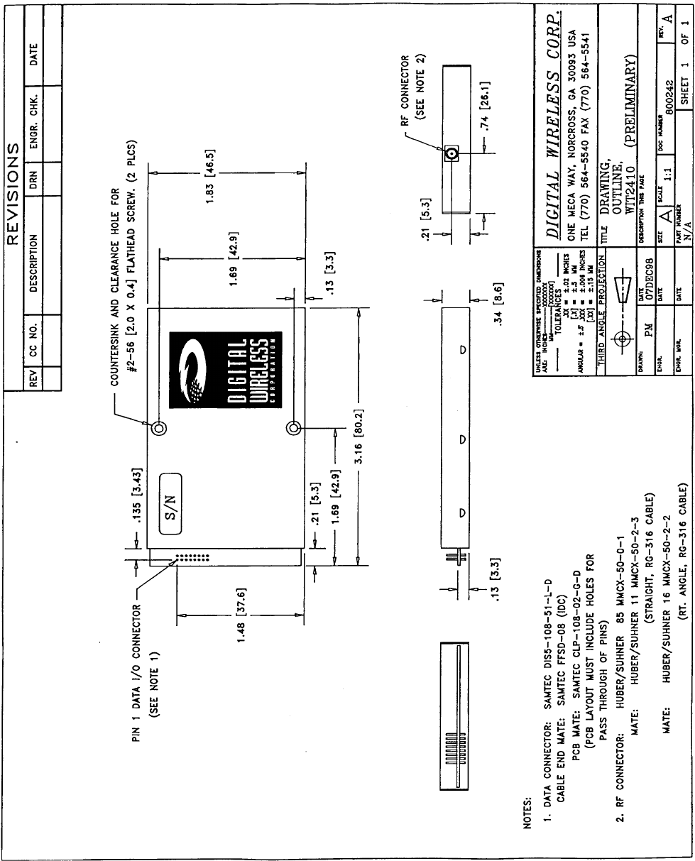
7.2.2. Mechanical Specifications
Weight 35g
Dimensions (including shield) 80.2 x 46.5 x 8.6mm
(refer to section 7.6 for mechanical drawing)
RF Connector:WIT Huber/Suhner: 85 MMCX 50-0-1
Mating Huber/Suhner: 11 MMCX-50-2-3 (straight)
Huber/Suhner: 16 MMCX-50-2-2 (rt. angle)
Data/Power Connector:
WIT Samtec: DIS5-108-51-L-D
Mating Samtec: FFSD-08 (IDC cable)
Samtec: CLP-108-02-G-D (PCB mount)

© 1999 Digital Wireless Corporation 29 6/15/99
7.3. Serial Connector Pinouts
Signal WIT2410M
OEM Pinout WIT2410E
DB9 Pinout
GND 1 5
TXD 2 3
RXD 3 2
CFG 4 -
RTS 5 7
SLEEP 6 4
DCD 7 1
CTS 8 8
The WIT2410E is wired as a DTE device and as such can be connected to DTE devices such
as PCs with a straight-through cable. When connecting a WIT2410E to a DCE device, a
“null modem” cable is required. To effect a null modem cable, cross-wire TXD and RXD
and connect ground. The WIT2410E can operate with just these three wires connected.
However, as the WIT2410 does not support software flow control, there will be no flow
control in this mode. If the DCE device fails to respond, connect DCD from the WIT2410E
to the DTR and RTS inputs to activate the DCE device whenever the WIT2410 asserts
carrier.
When connecting to the WIT2410M, make sure that all of the inputs (TXD, CFG, RTS and
SLEEP) are terminated for proper operation.
7.4. Approved Antennas
The WIT2410M is designed to ensure that no antenna other than the one fitted shall be used
with the device. The end user must permanently affix the antenna by using an adhesive on
the coupling such as Loctite, or ensure the antenna has a unique coupling. The table below
lists the antennas which can be purchased directly from Digital Wireless Corporation.
Contact DWC Technical Support with any questions.
Description Gain Part Number Coupling
YD24/15 Yagi Directional 14 dB YAGI2415 N
Om24/9 Omnidirectional 9 dB OMNI249 N
DWC Patch 6 dB PA2400 MMCX
Dipole 2 dB RWA249R Reverse SMA
7.5. Technical Support
For technical support call Digital Wireless Corporation at (770) 564-5540 between the hours
of 8:30AM and 5:30PM Eastern Time.
© 1999 Digital Wireless Corporation 30 6/15/99
7.6. Mechanical Drawing
© 1999 Digital Wireless Corporation 31 6/15/99
7.7. Warranty
Seller warrants solely to Buyer that the goods delivered hereunder shall be free from defects
in materials and workmanship, when given normal, proper and intended usage, for twelve (12)
months from the date of delivery to Buyer. Seller agrees to repair or replace at its option and
without cost to Buyer all defective goods sold hereunder, provided that Buyer has given Seller
written notice of such warranty claim within such warranty period. All goods returned to
Seller for repair or replacement must be sent freight prepaid to Seller’s plant, provided that
Buyer first obtain from Seller a Return Goods Authorization before any such return. Seller
shall have no obligation to make repairs or replacements which are required by normal wear
and tear, or which result, in whole or in part, from catastrophe, fault or negligence of Buyer,
or from improper or unauthorized use of the goods, or use of the goods in a manner for which
they are not designed, or by causes external to the goods such as, but not limited to, power
failure. No suit or action shall be brought against Seller more than twelve (12) months after
the related cause of action has occurred. Buyer has not relied and shall not rely on any oral
representation regarding the goods sold hereunder, and any oral representation shall not bind
Seller and shall not be a part of any warranty.
THE PROVISIONS OF THE FOREGOING WARRANTY ARE IN LIEU OF ANY
OTHER WARRANTY, WHETHER EXPRESS OR IMPLIED, WRITTEN OR ORAL
(INCLUDING ANY WARRANTY OR MERCHANT ABILITY OR FITNESS FOR A
PARTICULAR PURPOSE). SELLER’S LIABILITY ARISING OUT OF THE
MANUFACTURE, SALE OR SUPPLYING OF THE GOODS OR THEIR USE OR
DISPOSITION, WHETHER BASED UPON WARRANTY, CONTRACT, TORT OR
OTHERWISE, SHALL NOT EXCEED THE ACTUAL PURCHASE PRICE PAID BY
BUYER FOR THE GOODS. IN NO EVENT SHALL SELLER BE LIABLE TO
BUYER OR ANY OTHER PERSON OR ENTITY FOR SPECIAL, INCIDENTAL OR
CONSEQUENTIAL DAMAGES, INCLUDING, BUT NOT LIMITED TO, LOSS OF
PROFITS, LOSS OF DATA OR LOSS OF USE DAMAGES ARISING OUT OF THE
MANUFACTURE, SALE OR SUPPLYING OF THE GOODS. THE FOREGOING
WARRANTY EXTENDS TO BUYER ONLY AND SHALL NOT BE APPLICABLE
TO ANY OTHER PERSON OR ENTITY INCLUDING, WITHOUT LIMITATION,
CUSTOMERS OF BUYERS.