Murata Electronics North America CM2201N TRANSCEIVER MODULE User Manual cm2201d vp
Murata Electronics North America TRANSCEIVER MODULE cm2201d vp
USERS MANUAL
1
®
CM2201N
Rating Value Units
All Input/Output Pins -0.3 to +4.0 V
Non-Operating Ambient Temperature Range -50 to +100 oC
Absolute Maximum Ratings
Custom
Electrical Characteristics
Characteristic Sym Notes Minimum Typical Maximum Units
Operating Frequency fO916.30 916.70 MHz
Modulation Type OOK
Encoded Data RF Transmission Rate 4.8 kb/s
Peak Radiated Field Strength (FCC OP-1) EO20,000 µV/m
Battery CR2032
Digital Input Logic High (Sensor) 2.4 VDD V
Digital Input Logic Low (Sensor) 0 0.45 V
Operating Ambient Temperature Range TA-40 +85 oC
916.50 MHz
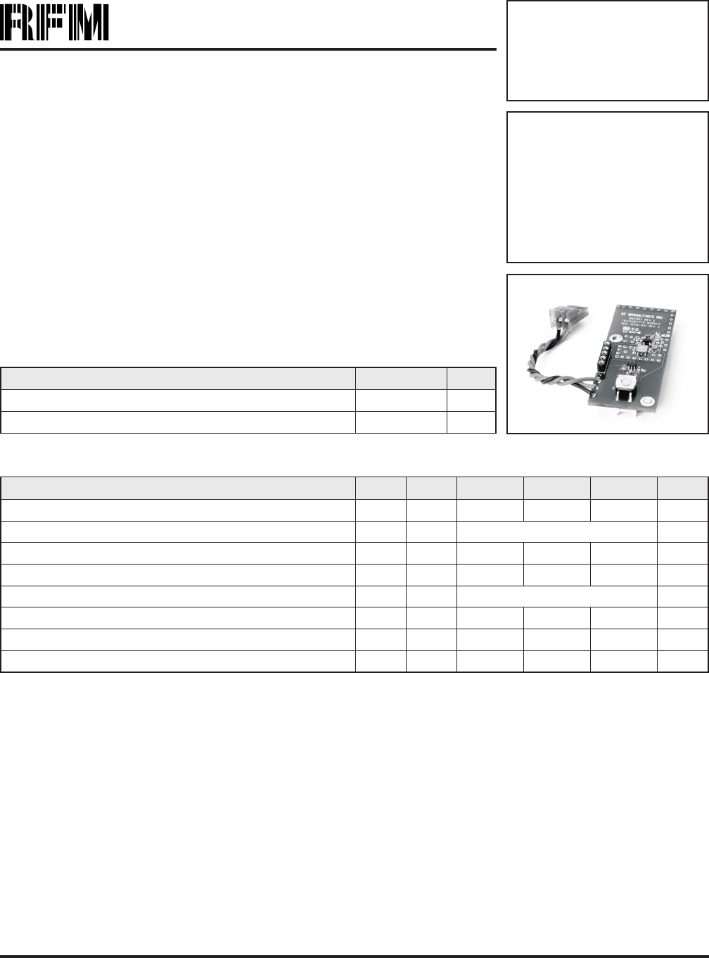
Transmitter
Module
The CM2201N is a 916.5 MHz transmitter module designed to monitor industrial alarm
sensors. Communication range in an “open field” environment is typically 100 meters.
The CM2201N combines RFM’s very low-current SAW resonator stabilized transmitter
technology with low-power microcontroller technology to achieve long battery life. The
module is compatible with RFM’s miniMESHTM network protocol, which provides add-on
“plug-and-play” multicast mesh network routing. The CM2201N is certified for operation
under FCC 15.249 regulations.
•Integrated Sensor Interface
•Very Low Current Operation from a CR2032 Battery
•Compatible with RFM miniMESHTM Network Protocol
•Ready-to-Use Module
2
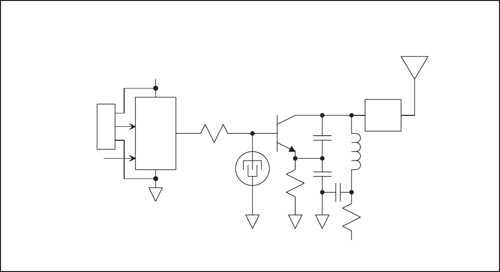
Theory of Operation
The major components of the CM2201N include an
RFM SAW resonator stabilized transmitter and a
Microchip PIC12F200 microcontroller. The transmitter
operates on a frequency of 916.5 MHz, at a nominal
output power of 0.5 mW. The microcontroller gener-
ates “heart beat” transmissions periodically, plus an
immediate transmission in the event of a sensor alarm
or test button activation. The CM2201N is powered by
a replaceable 3 V CR2032 lithium “coin cell” battery.
The CM2201N is compatible with RFM’s miniMESHTM
network protocol, which provides add-on “plug-and-
play” multicast mesh network routing to improve com-
munication range and robustness.
FCC Labels and Notices
This device complies with Part 15 of the FCC rules.
Operation is subject to the following two conditions:
(1) this device may not cause harmful interference,
and (2) this device must accept any interference re-
ceived, including interference that may cause unde-
sired operation.
A clearly visible label is required on the outside of the
user’s (OEM) enclosure stating that this product con-
tains a CM2205 radio module, FCC ID: TE6-
CM2201N.
WARNING: This device operates under Part 15 of the
FCC rules. Any modification to this device, not ex-
pressly authorized by RF Monolithics, Inc., may void
the user’s authority to operate this device.
+
+
Test Button
SAW
Resonator
M icrocontroller
C M 2201N Sensor Transm itter B lock D iagram
Pow er Supply is a 3 V
C R 2032 "C oin C ell"
B a tte ry
J2-2
J2-1
J2-3
SNR PW R
SENSOR
GND
Tuning
Figure 1

Pin Name Description
J2-1 SNR PWR This pad is the +3 V power supply for the external alarm sensor.
J2-2 SENSOR This pad is a logic input driven by the external alarm sensor.
J2-3 GND This pad is the ground return for the external alarm sensor.
J3-1 VPP This pad is used to program the microcontroller. No connection should be made to it in normal operation.
J3-2 VDD This pad is used to program the microcontroller. No connection should be made to it in normal operation.
J3-3 GND This pad is used to program the microcontroller. No connection should be made to it in normal operation.
J3-4 PGD This pad is used to program the microcontroller. No connection should be made to it in normal operation.
J3-5 PGC This pad is used to program the microcontroller. No connection should be made to it in normal operation.
3
Pin and Pad Descriptions
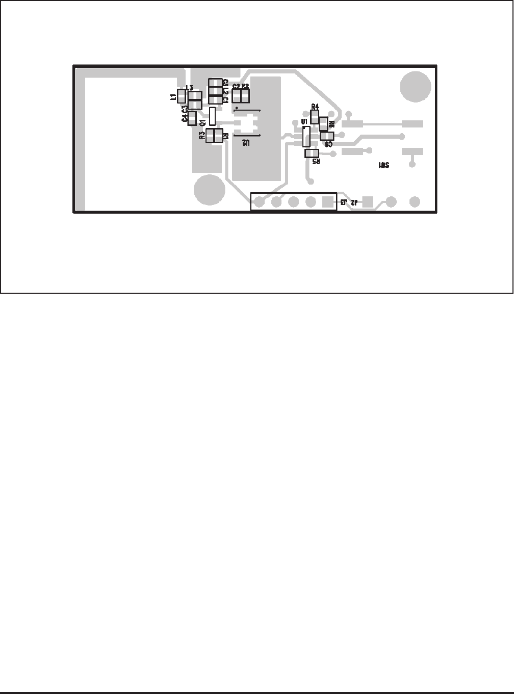
4
CM 2201 Top View
GND
SENSO R
SNR PW R
VPP
VDD
GND
PGD
PGC
J2J3
Figure 2
Note: Specifications subject to change without notice.
file: CM2201Nd.vp, 2005.10.18 rev