Murata Electronics North America CM2202N Remote Data Transmitter User Manual CM2202 vp
Murata Electronics North America Remote Data Transmitter CM2202 vp
User Manual
1
®CM2202N
Rating Value Units
All In put/Out put Pins -0.3 to +4.0 V
Non-Operating Am bi ent Tem per a ture Range -40 to +85 oC
Ab so lute Max i mum Rat ings
Cus tom
Elec tri cal Char ac ter is tics
Characteristic Sym Notes Minimum Typical Maximum Units
Op er ating Fre quency fO916.30 916.70 MHz
Mod u la tion Type OOK
En coded Data RF Trans mis sion Rate 4.8 kb/s
Peak Radiated Field Strength (FCC OP-1) EO20,000 µV/m
Bat tery BR1225
Dig i tal In put Logic High (Sen sor) .85 VDD VDD V
Dig i tal In put Logic Low (Sen sor) 0.15 VDD V
Op er ating Am bi ent Tem per a ture Range TA-20 +70 oC
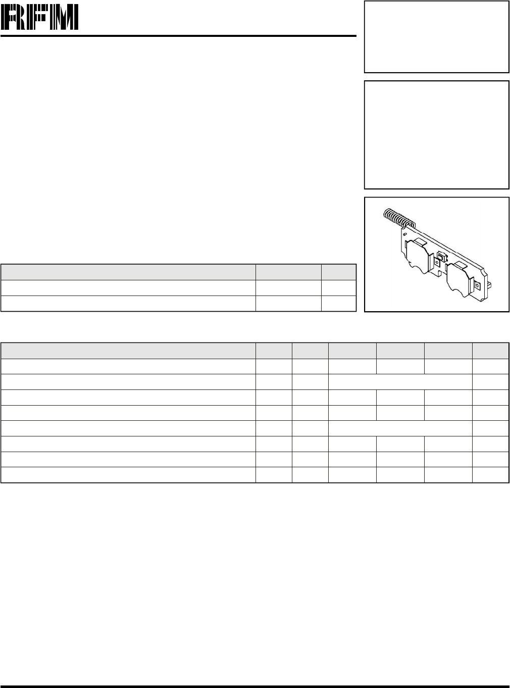
916.50 MHz
Transmitter
Module
The CM2202N is a 916.5 MHz trans mit ter mod ule de signed to mon i tor in dus trial alarm
sen sors. Com mu ni ca tion range in an “open field” en vi ron ment is typ i cally 100 me ters.
The CM2202N com bines RFM’s very low-cur rent SAW res o na tor sta bi lized trans mit ter
tech nol ogy with low-power microcontroller tech nol ogy to achieve long bat tery life. The
mod ule is com pat i ble with RFM’s miniMESHTM net work pro to col, which pro vides add-on
“plug-and-play” multicast mesh net work rout ing. The CM2202N is cer ti fied for op er a tion
un der FCC 15.249 reg u la tions.
•In te grated Sen sor In ter face
•Very Low Cur rent Op er a tion from 2 BR1225 Bat teries
•Com pat i ble with RFM miniMESHTM Net work Pro to col
•Ready-to-Use Mod ule
2
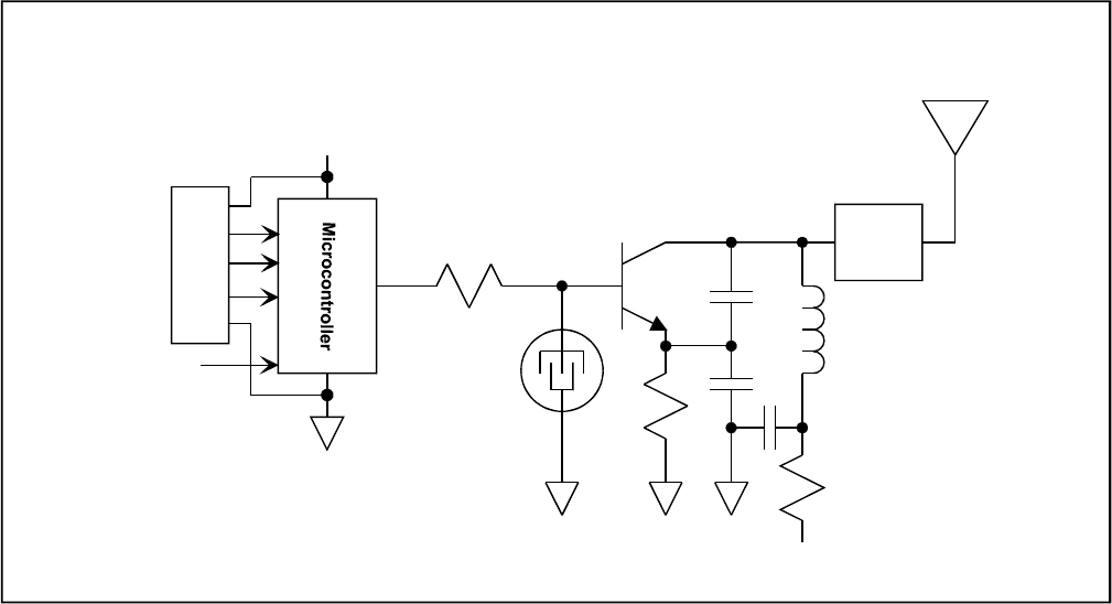
The ory of Op er a tion
The ma jor com po nents of the CM2202N in clude an
RFM SAW res o na tor sta bi lized trans mit ter and a
Micro chip PIC12F635 microcontroller. The trans mit ter
op er ates on a fre quency of 916.5 MHz, at a nom i nal
out put power of 0.5 mW. The microcontroller gen er
-
ates “heart beat” trans mis sions pe ri od i cally, plus an
im me di ate trans mis sion in the event of a sen sor alarm
or test but ton ac ti va tion. The CM2202N is pow ered by
2 re place able 3 V BR1225 lith ium “coin cell” bat tery.
The CM2202N is com pat i ble with RFM’s miniMESHTM
net work pro to col, which pro vides add-on “plug-and-
play” multicast mesh net work rout ing to im prove com
-
mu ni ca tion range and ro bust ness.
FCC La bels and No tices
This de vice com plies with Part 15 of the FCC rules.
Op er a tion is sub ject to the fol low ing two con di tions:
(1) this de vice may not cause harm ful in ter fer ence,
and (2) this de vice must ac cept any in ter fer ence re -
ceived, in clud ing in ter fer ence that may cause un de
-
sired op er a tion.
A clearly vis i ble la bel is re quired on the out side of the
user’s (OEM) en clo sure stat ing that this prod uct con
-
tains a CM2202N ra dio mod ule, FCC ID:
TE6-CM2202N.
WARNING: This de vice op er ates un der Part 15 of the
FCC rules. Any mod i fi ca tion to this de vice, not ex-
pressly au tho rized by RF Monolithics, Inc., may void
the user’s au thor ity to op er ate this de vice.
+
+
TestButton
SAW
Resonator
CM2202N Sensor Transmitter Block Diagram
Power Su pply is 2
3VBR1225 "CoinCell"
Batteries
Tuning
J2-2
J2-3
J2-1
J2-5
J2-4
Figure 1

Pin Name Description
J2-1 GND This pad is the ground return for the ex ter nal alarm sen sor.
J2-2 SENSOR This pad is a logic in put driven by the ex ter nal alarm sen sor.
J2-3 SNR Power This pad is the +3V power supply for the ex ter nal alarm sen sor.
J2-4 Pclk This pad is used to pro gram the microcontroller. No con nec tion should be made to it in nor mal op er a tion.
J2-5 VDD This pad is used to pro gram the microcontroller. No con nec tion should be made to it in nor mal op er a tion.
3
Pin and Pad De scrip tions
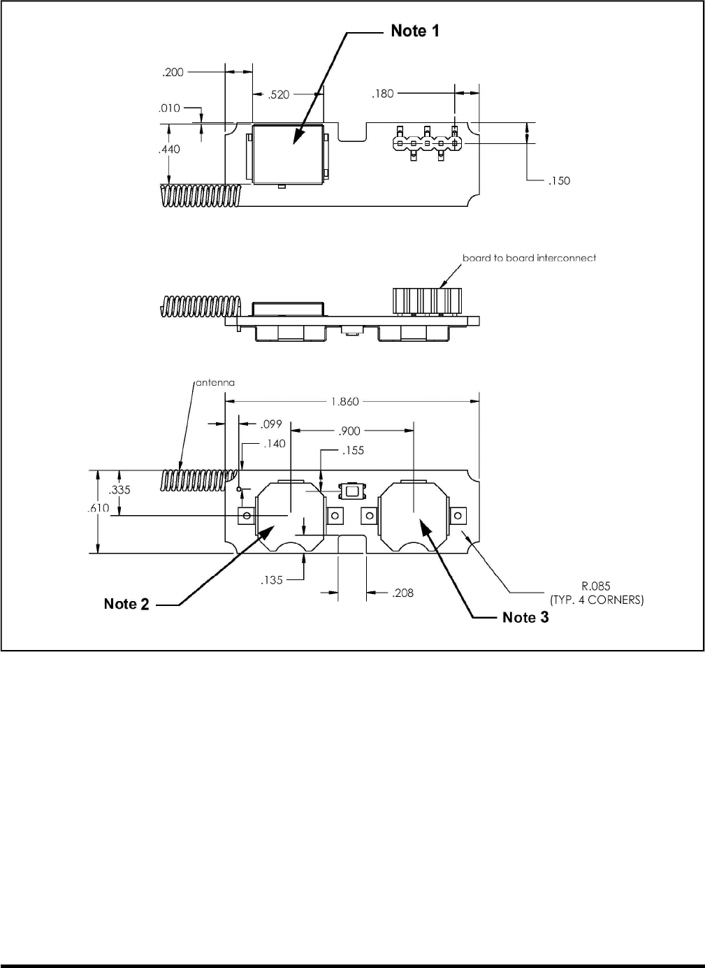
4
Figure 2
Note 1: La ser mark on shield top with FCC ID and made in Phil ip pines.
Note 2: Place la bel with bar code and al pha nu meric se rial num ber.
Note 3: Place la bel with bat tery ori en ta tion.
Note: Spec i fi ca tions sub ject to change with out no tice.
file: CM2202.vp, 031006 rev