Murata Electronics North America DNT500P DNT500 900 MHz Transceiver Module User Manual part 3
Murata Electronics North America DNT500 900 MHz Transceiver Module part 3
Contents
part 3 user manual
DNT500
2008 by RF Monolithics, Inc. 47 M-0500-0000 Rev D
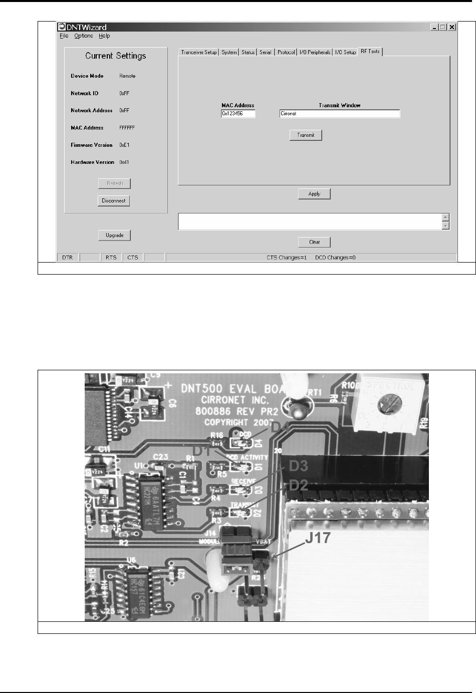
Figure 5.5.10
5.6 DNT500 Interface Board Features
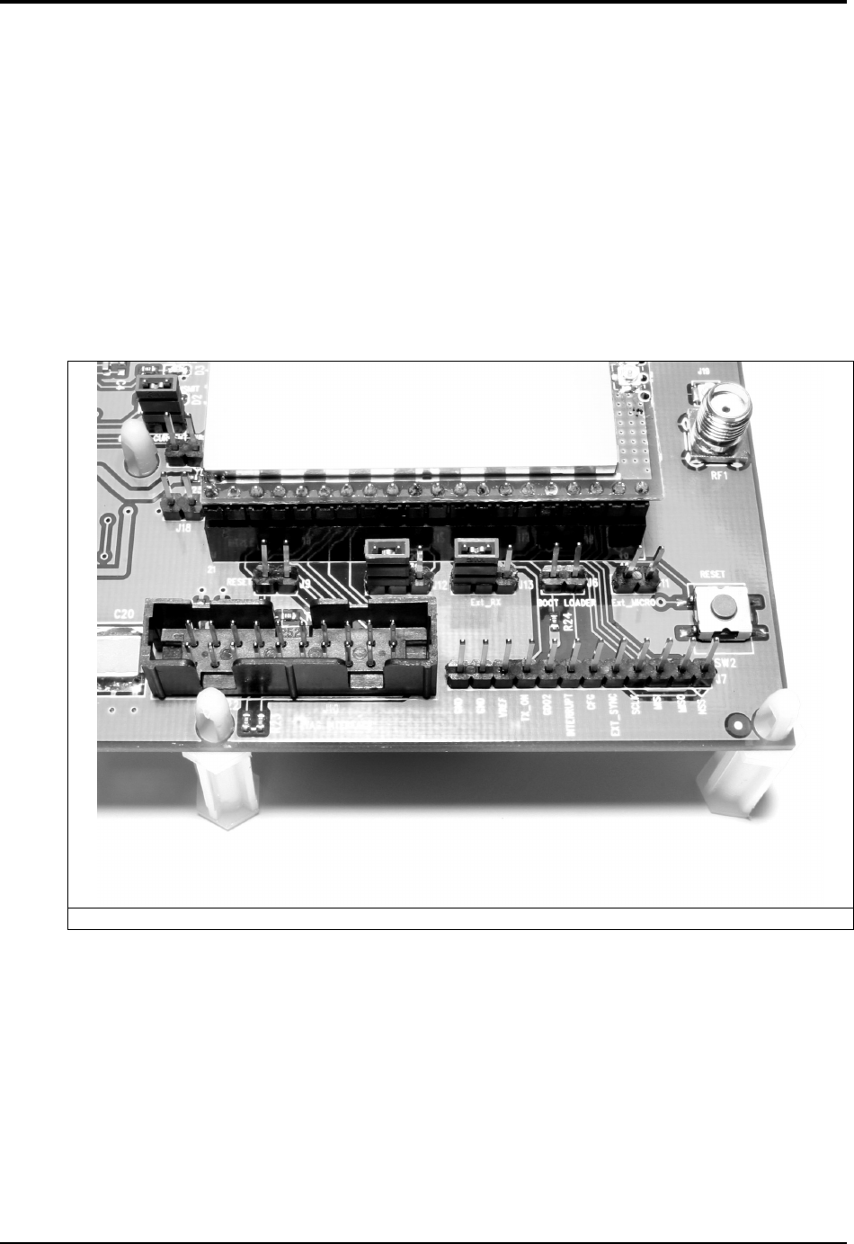
The location of LEDs D1 through D4 and jumper pin sets J14 and J17 are shown in Fig-
ure 5.6.1.
Figure 5.6.1
DNT500
2008 by RF Monolithics, Inc. 48 M-0500-0000 Rev D
Amber DCD LED D4 illuminates on a remote to indicate it is registered with the base
station and can participate in RF communications. LED D4 illuminates on the base sta-
tion when one or more remotes are registered to it. Green Activity LED D1 illuminates
on a remote when transmitting data, and illuminates on a base when receiving data. Red
Receive LED D3 illuminates when sending received data through the serial port to the
PC. Green Transmit LED D2 illuminates when the PC sends data through the serial port
to be transmitted.
Jumper pin set J14 is provided to allow measurement of the DNT500P current. For nor-
mal operation J14 has a shorting plug installed. Jumper pin set J17 allows the DNT500P
CFG pin to be grounded by installing a shorting plug. This places the DNT500P in proto-
col mode.
Figure 5.6.2
Figure 5.6.2 shows the connectors to the right of the DNT500P mounting socket. Jumper
pin set J9 allow the DNT500P reset line to be routed to JTAG interface connector J10.
J18 allows the DNT500P reset line to be grounded. Note that the JTAG operation is usu-
ally limited to factory testing. For normal operation pin sets J9 and J18 should not have a
shorting block installed. Jumper pin sets J12 and J13 normally have shorting plugs in-
stalled as shown in Figure 5.6.2, which connects the DNT500P UART0_TXD and
UART0_RXD pins to the respective serial data lines on the evaluation board. It is possi-
ble to connect directly to UART0_TXD and UART0_RXD by moving the jumpers over.
In this case, J11-1 is the input for transmitted data and J11-2 is the output for received
data. Note this a 3 V logic interface. Placing a shorting plug on jumper pin set J6 allows
DNT500
2008 by RF Monolithics, Inc. 49 M-0500-0000 Rev D
the DNT500P to be powered up in boot loader mode. This is used for factory code loads
and functional testing. The DNT500 has its own boot loader utility that allows the proto-
col firmware to be installed with a terminal program that supports YMODEM. Pin strip
J7 provides access to various DNT500 pins as shown on the silkscreen. Pressing switch
SW2 will reset the DNT500P.
Figure 5.6.3
Figure 5.6.3 shows the connectors to the left of the DNT500P mounting socket. Pressing
switch SW2 switches GPIO0 from logic high to logic low. Pin strip J8 provides access to
various DNT500 pins as shown on the silkscreen. The wiper of pot R10 drives the input
of ADC1. Clockwise rotation of the pot wiper increases the voltage. Thermistor RT1 is
part of a voltage divider that drives ADC0. LED D5 illuminates when GPIO1 is set as a
logic high output. LED D10 illuminates when GPIO3 is set as a logic high. The
DNT500P interface board includes a 5 V regulator to regulate the input from the 9 V wall
transformer power supply. Note: do not attempt to use the 9 V wall transformer power
supply to power the DNT500P directly. The maximum allowed voltage input to the
DNT500P is 5.5 V.

DNT500
2008 by RF Monolithics, Inc. 50 M-0500-0000 Rev D
6. Demonstration Procedure
The procedure below provides a quick demonstration of the DNT500 using a
DNT500DK development kit:
1. Confirm that each DNT500P is installed correctly in an interface board, and that
the U.FL jumpers between the DNT500P radios and the interface boards are in-
stalled. Also confirm that a dipole antenna is installed on each interface board,
and that J14 has a jumper block installed on each interface board. See Figures
5.4.1, 5.4.2 and 5.4.3 above.
2. Attach each transceiver/interface board to a computer with the DNT500 Wizard
utility program installed. Place the transceivers at least 3 feet (one meter) apart.
3. Start the DNT500 Wizard utility program on both computers.
4. On each computer, press the Connect button on the Wizard window. This will
open a serial port setup dialog box. Set the baud rate to 115.2 kb/s and select the
COM port the DNT500 is connected to. Parameter values on the left of the Wiz-
ard main window and on the Transceiver Setup tab will fill in.
5. Select the RF Test tab on the Wizard. A message placed in the Transmit Window
is sent to the specified MAC address each time the Apply button is pressed. Mes-
sages received are displayed in the lower text box. The receive message text box
can be cleared with the Clear button.

DNT500
2008 by RF Monolithics, Inc. 51 M-0500-0000 Rev D
7. Troubleshooting
DNT500 not responding:
Make sure DTR is asserted (logic low) to bring the radio out of sleep mode.
Cannot enter protocol mode:
Make sure the host data rate is correct. The DNT500 defaults to 115.2 kb/s. If using the
escape sequence command, make sure a pause of at least 20 ms precedes the escape se-
quence.
A remote never detects carrier (DCD):
Check that the base station is running, and that the remote InitialNwkID parameter is the
same as the base station, or is set to 0xFF. Also check that remote is receiving an ade-
quate signal from the base station.
Carrier is detected, but no data appears to be received:
Make sure that RTS is asserted to enable receive character flow. Make sure the RF
transmit power is not on a high settings if the nodes are close together.
The DNT500 is interfering with other nearby circuits:
It is possible for the RF energy from the DNT500 to be rectified by nearby circuits that
are not shielded for RF, manifesting as a lower frequency pulse noise signal. If possible,
place the antenna at least 1 foot away from the transceiver module, and 3 feet from other
system circuit boards. Place sensitive circuits in a grounded metal casing to keep out RFI.
Range is extremely limited:
This is usually a sign of a poor antenna connection or the wrong antenna. Check that the
antenna is firmly connected. If possible, remove any obstructions in the near field of the
antenna (nominal 3 ft radius).
Transmitting terminal flashes (drops) CTS occasionally:
This indicates that the transmitter is unable to reliably get its data across. This may be the
result of an interfering signal, but most often is caused by overloading of the network.
Adjusting the protocol parameters may increase the network efficiency.
Receiving terminal drops characters periodically:
Set the number of retries to a high number and send a few characters. Check that the
transmitted data can get through under these conditions. Sometimes this symptom is
caused by an application that is explicitly dependent on the timing of the received data
stream. The nature of the RF channel imposes a degree of unpredictability in the end-to-
end transmission delay.

DNT500
2008 by RF Monolithics, Inc. 52 M-0500-0000 Rev D
8. APPENDICES
8.1 Ordering Information
DNT500 OEM Transceiver Module (solder pad mounting)
DNT500P OEM Transceiver Module (pin-socket mounting)
8.2 Technical Support
For DNT500 technical support call RFM at (678) 684-2000 between the hours of
8:30AM and 5:30PM Eastern Time.
DNT500
2008 Cirronet
Inc 53 M-0500-0000 Rev B
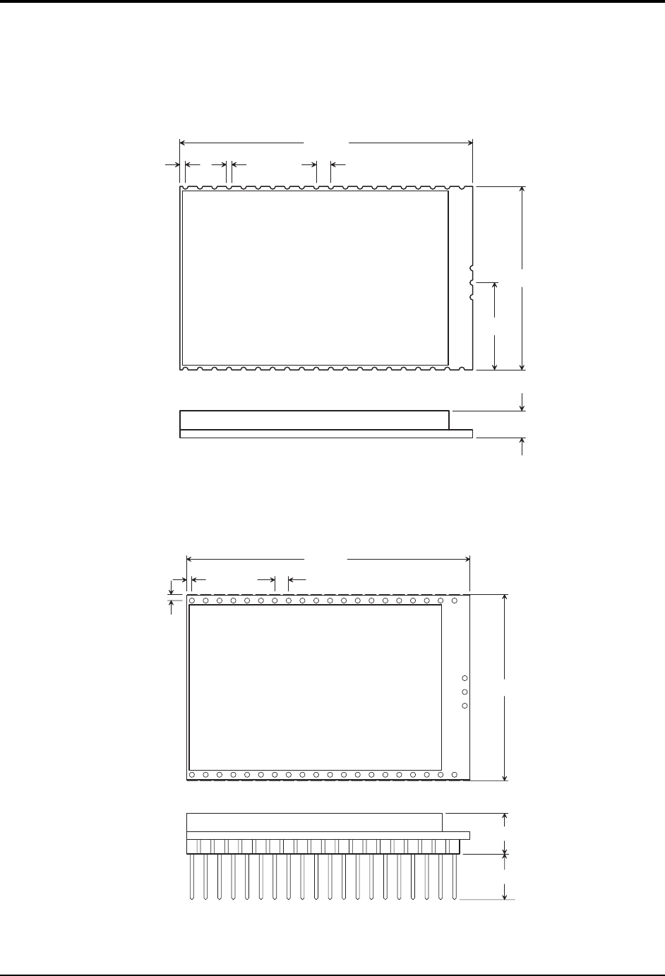
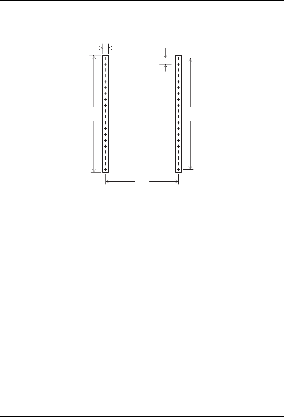
8.3 DNT500 Mechanical Specifications
D N T 5 0 0 O u t l i n e a n d M o u n t i n g D i m e n s i o n s
D i m e n s i o n s i n i n c h e s
2 . 0 1 0
1 . 2 6 0
0 . 5 9 5
0 . 1 8 0
0 . 0 4 0 0 . 0 4 0 0 . 1 0 0
1
4 0
4 2
D N T 5 0 0 P O u t l i n e a n d M o u n t i n g D i m e n s i o n s
D i m e n s i o n s i n i n c h e s
2 . 0 5 0
0 . 2 8 5
0 . 0 4 0 0 . 1 0 0
0 . 3 3 3
0 . 0 5 0
1 . 3 6 0
1
4 0
DNT500
2008 Cirronet
Inc 54 M-0500-0000 Rev B
1 . 9
( 4 8 . 3 )
2 . 0
( 5 0 . 8 )
0 . 1
( 2 . 5 )
D N T 5 0 0 P I n t e r f a c e C o n n e c t o r
P C B L a y o u t D e t a i l
0 . 1
( 2 . 5 )
C o n n e c t o r s a r e F C I E l e c t r o n i c s 7 5 9 1 5 - 4 2 0 L F o r e q u i v a l e n t
D i m e n s i o n s i n i n c h e s a n d ( m m )
1 . 2 6
M i n i m u m p l a t e d P C B
h o l e d i a m e t e r 0 . 0 3 ( 0 . 7 5 )

DNT500
2008 Cirronet
Inc 55 M-0500-0000 Rev B
9. Warranty
Seller warrants solely to Buyer that the goods delivered hereunder shall be free from de-
fects in materials and workmanship, when given normal, proper and intended usage, for
twelve (12) months from the date of delivery to Buyer. Seller agrees to repair or replace at
its option and without cost to Buyer all defective goods sold hereunder, provided that
Buyer has given Seller written notice of such warranty claim within such warranty period.
All goods returned to Seller for repair or replacement must be sent freight prepaid to
Seller’s plant, provided that Buyer first obtain from Seller a Return Goods Authorization
before any such return. Seller shall have no obligation to make repairs or replacements
which are required by normal wear and tear, or which result, in whole or in part, from ca-
tastrophe, fault or negligence of Buyer, or from improper or unauthorized use of the
goods, or use of the goods in a manner for which they are not designed, or by causes ex-
ternal to the goods such as, but not limited to, power failure. No suit or action shall be
brought against Seller more than twelve (12) months after the related cause of action has
occurred. Buyer has not relied and shall not rely on any oral representation regarding the
goods sold hereunder, and any oral representation shall not bind Seller and shall not be a
part of any warranty.
THE PROVISIONS OF THE FOREGOING WARRANTY ARE IN LIEU OF ANY
OTHER WARRANTY, WHETHER EXPRESS OR IMPLIED, WRITTEN OR
ORAL (INCLUDING ANY WARRANTY OR MERCHANT ABILITY OR
FITNESS FOR A PARTICULAR PURPOSE). SELLER’S LIABILITY ARISING
OUT OF THE MANUFACTURE, SALE OR SUPPLYING OF THE GOODS OR
THEIR USE OR DISPOSITION, WHETHER BASED UPON WARRANTY,
CONTRACT, TORT OR OTHERWISE, SHALL NOT EXCEED THE ACTUAL
PURCHASE PRICE PAID BY BUYER FOR THE GOODS. IN NO EVENT
SHALL SELLER BE LIABLE TO BUYER OR ANY OTHER PERSON OR
ENTITY FOR SPECIAL, INCIDENTAL OR CONSEQUENTIAL DAMAGES,
INCLUDING, BUT NOT LIMITED TO, LOSS OF PROFITS, LOSS OF DATA OR
LOSS OF USE DAMAGES ARISING OUT OF THE MANUFACTURE, SALE OR
SUPPLYING OF THE GOODS. THE FOREGOING WARRANTY EXTENDS TO
BUYER ONLY AND SHALL NOT BE APPLICABLE TO ANY OTHER PERSON
OR ENTITY INCLUDING, WITHOUT LIMITATION, CUSTOMERS OF
BUYERS.