Murata Electronics North America XDM2140 Modular 2.4GHz Transceiver User Manual
Murata Electronics North America Modular 2.4GHz Transceiver Users Manual
Users Manual

5015 B.U. Bowman Drive Buford, GA 30518 USA Voice: 770-831-8048 Fax: 770-831-8598
Certification Exhibit
FCC ID: HSW-XDM2140
IC: 4492A-XDM2140
FCC Rule Part: 15.247
IC Radio Standards Specification: RSS-210
ACS Report Number: 08-0352 - 15C
Manufacturer: RFM / Cirronet Inc.
Model: XDM2140
Manual
www.RFM.com E-mail: info@rfm.com Technical support +1.800.704.6079 Page 1 of 36
©2008 by RF Monolithics, Inc. E-mail: tech_sup@rfm.com XDM2140 - 09/16/08
Intergration Guide
3079 Premiere Parkway, Suite 140
Duluth, GA 30097

www.RFM.com E-mail: info@rfm.com Technical support +1.800.704.6079 Page 2 of 36
©2008 by RF Monolithics, Inc. E-mail: tech_sup@rfm.com XDM2140 - 09/16/08
Important Regulatory Information
Cirronet DUST Network module
FCC ID: HSW-XDM2140
IC: 4492A-XDM2140
THIS DEVICE COMPLIES WITH PART 15 OF THE FCC RULES. OPERATION IS SUBJECT TO THE
FOLLOWING TWO CONDITIONS. (1) THIS DEVICE MAY NOT CAUSE HARMFUL INTERFERENCE,
AND (2) THIS DEVICE MUST ACCEPT ANY INTERFERENCE RECEIVED, INCLUDING
INTERFERENCE THAT MAY CAUSE UNDESIRED OPERATION.
This Class B digital apparatus complies with Canadian ICES-003.
Cet appareil numérique de la classe B est conforme à la norme NMB-003 du Canada.
FCC User Information
“NOTE: This equipment has been tested and found to comply with the limits for a Class B digital device,
pursuant to Part 15 of the FCC Rules. These limits are designed to provide reasonable protection
against harmful interference in a residential installation. This equipment generates, uses, and can radiate
radio frequency energy and, if not installed and used in accordance with the instructions, may cause
harmful interference to radio communications. However, there is no guarantee that interference will not
occur in a particular installation. If this equipment does cause harmful interference to radio or television
reception, which can be determined by turning the equipment off and on, the user is encouraged to try to
correct the interference by one or more of the following measures:
• Reorient or relocate the receiving antenna.
• Increase the separation between the equipment and receiver.
• Connect equipment to an outlet on a circuit different in which the receiver is connected.
• Consult the dealer or an experienced radio/TV technician for help.”
Warning: Changes or modifications to this device not expressly approved by RFM Inc.
could void the user’s authority to operate the equipment.
RF Exposure
In accordance with FCC requirements of human exposure to radiofrequency fields, the radiating element
shall be installed such that a minimum separation distance of 20cm shall be maintained from the user
and/or general population.
Industry Canada
This Class B digital apparatus meets all requirements of the Canadian Interference Causing Equipment
Regulations. Operation is subject to the following two conditions: (1) this device may not cause harmful
interference, and (2) this device must accept any interference received, including interference that may
cause undesired operation.
Cet appareillage numérique de la classe B répond à toutes les exigences de l'interférence canadienne
causant des règlements d'équipement. L'opération est sujette aux deux conditions suivantes: (1) ce
dispositif peut ne pas causer l'interférence nocive, et (2) ce dispositif doit accepter n'importe quelle
interférence reçue, y compris l'interférence qui peut causer l'opération peu désirée.

www.RFM.com E-mail: info@rfm.com Technical support +1.800.704.6079 Page 3 of 36
©2008 by RF Monolithics, Inc. E-mail: tech_sup@rfm.com XDM2140 - 09/16/08
“To reduce potential radio interference to other users, the antenna type and its gain should be so
chosen that the equivalent isotropically radiated power (e.i.r.p.) is not more than that permitted for
successful communication.”
“This device has been designed to operate with the antennas listed below, and having a maximum
gain of 12 dB. Antennas not included in this list or having a gain greater than 12 dB are strictly
prohibited for use with this device. The required antenna impedance is 50 ohms.”
RFM 12 dB Patch Antenna
RFM 9 dB Monopole Antenna
OEM Installation and Compliance Labeling
The XDM2140 module is labeled with its own FCC ID number, and, if the FCC ID is not visible when the module
is installed inside another device, then the outside of the device into which the module is installed must also display
a label referring to the enclosed transmitter module.
This exterior label can use wording such as the following:
“Contains Transmitter Module FCC ID: HSW-XDM2140” or
“Contains FCC ID: HSW-XDM2140”
Any similar wording that expresses the same meaning may be used. The Grantee may either provide such a label,
an example of which must be included in the application for equipment authorization, or, must provide adequate
instructions along with the module which explain this requirement. In the latter case, a copy of these instructions
must be included in the application for equipment authorization.
The antenna connections from the module to the certain antennas approved with this device are not unique and
require Professional installation.
www.RFM.com E-mail: info@rfm.com Technical support +1.800.704.6079 Page 4 of 36
©2008 by RF Monolithics, Inc. E-mail: tech_sup@rfm.com XDM2140 - 09/16/08
XDM2140
2.4 GHz
Ultra Low Power
Mesh
RF Transceiver
Module
Product Overview
Based on DUST Networks’ SmartMesh-XD™ technology, RFM’s XDM2140
module is designed to provide excellent communications reliability and long
battery life in a wide range of sensor network applications. The XDM2140’s
combination of an IEEE802.15.4 transceiver and Time Synchronized Mesh
Protocol (TSMP) blends the reliability of self-organizing and self-healing mesh
networking with synchronized power duty cycling to achieve very long battery
life operation. The XDM2140 is tailored for use in battery and line powered
wireless devices for applications that require proven performance and
scalability. The multifunctional interface of the XDM2140 gives it the flexibility
to be used in a wide variety of applications, from energy management to
building control to machine health monitoring. The XDM2140 requires no
embedded programming, greatly reducing the development time and cost of a
wireless sensor network application. The XDM2140 is certified for unlicensed
operation in the USA, Canada and Europe. The XDM2140 complies with
Directive 2002/95/EC (RoHS) Pb
Key Features
Ultra Low Power Consumption
• Innovative radio design consumes 80% less
power in receive mode than competing solutions
• Ultra-efficient power usage, enabled through
SmartMesh Intelligent Network management,
delivers over a decade of network operation on
two AA batteries
• Automatic network-wide coordination for
efficient power usage
Ultra Reliable Networking
• SmartMesh-XD™ protocol delivers greater
than 99.9% typical network reliability
• Frequency hopping provides interference
rejection and minimizes multipath fading
• Mesh networking provides built-in redundancy
• Every XDM2140 acts as both and endpoint and
a router, increasing network reliability with
mesh-to-the edge™
• Automatic self-organizing mesh networking
capability built in
Easy Integration
• XDM2140 provides all the module functionality
with no embedded programming or complex
configuration requirements
• XDM2140 interfaces is well designed and
multi-functional
• High-level Data Link Control (HDLC) serial
interface includes bi-directional flow control
• Industrial temperature range -40 to +85 °C
• XDM2140P version for plug in installation,
XDM2140C version for solder reflow
Applications
• Building Monitoring and Control
• Machine Health Monitoring
• Structural Integrity Monitoring
• Energy Management
• Asset Management
• Temperature Monitoring
• Urban Infrastructure Monitoring
• Agricultural/Forestry Sensor Networks
Table of Contents
1.0 XDM2140 Introduction............................................................................................................................4
2.0 Absolute Maximum Ratings....................................................................................................................6
3.0 Normal Operating Conditions .................................................................................................................6
3.1 Current Consumption........................................................................................................................6
4.0 Electrical Specifications..........................................................................................................................7
4.1 Device Load ......................................................................................................................................7
4.2 Digital I/O Type 1 ..............................................................................................................................7
4.3 Digital I/O Type 2 ..............................................................................................................................7
5.0 RF Specifications ...................................................................................................................................8
5.1 Radio Specifications .........................................................................................................................8
5.2 Antenna Specifications .....................................................................................................................8
6.0 Module Pinout ........................................................................................................................................9
7.0 Boot Sequence.....................................................................................................................................10
8.0 Hardware Interfaces .............................................................................................................................10
8.1 /RESET IN .....................................................................................................................................10
8.2 /TIME .............................................................................................................................................10
8.3 /LED ...............................................................................................................................................11
8.4 Settable I/O Modes ........................................................................................................................11
8.4.1 Mode1 - Three/Four/Five-signal Serial Interface (9600 b/s) ................................................11
8.4.2 Mode 3 - Five-signal Serial Interface (9600 b/s) ..................................................................12
8.4.3 UART Timing Values............................................................................................................13
9.0 Command Set ......................................................................................................................................15
9.1 Command Data Types....................................................................................................................15
9.2 Command Format...........................................................................................................................15
9.2.1 Command 0x80 - Serial Payload Sent to Serial Port ...........................................................16
9.2.2 Command 0x81 - Unacknowledged Serial Payload Received from Serial Port ..................16
9.2.3 Command 0x82 - Acknowledged Serial Payload Received from Serial Port.......................17
9.2.4 Command 0x84 - Time/State Packet ...................................................................................17
9.2.5 Commands 0x87 and 0x88 - Set Parameter Request/Response........................................ 18
9.2.6 Commands 0x89 and 0x8A - Get Parameter Request/Response ....................................... 18
9.2.7 Command 0x8C - XDM2140 Information .............................................................................19
9.2.8 Command 0x8D - Reset XDM2140......................................................................................19
9.2.9 Command 0x09 - Deep Sleep..............................................................................................19
9.3 Get/Set Command Parameters .....................................................................................................20
9.3.1 Error Codes ..........................................................................................................................21
9.3.2 Parameter Type 0x01 - Network ID......................................................................................21
9.3.3 Parameter Type 0x02 - XDM2140 State..............................................................................21
9.3.3.1 Configuration Change Flag (CCF) ..............................................................................23
9.3.4 Parameter Type 0x03 - Frame Length .................................................................................23
9.3.5 Parameter Type 0x04 - Join Key..........................................................................................23
9.3.6 Parameter Type 0x05 - Time/Status ....................................................................................24
9.3.7 Parameter Type 0x07 - XDM2140 Information ....................................................................24
9.3.8 Parameter Type 0x08 - Power Amplifier ..............................................................................25
9.3.9 Parameter Type 0x0A - Charge Consumption.....................................................................26
9.3.10 Parameter Type 0x0B - Power Source ..............................................................................27
9.4 HDLC Packet Examples .................................................................................................................28
10.0 XDM2140 Outline Drawings ...............................................................................................................31
10.1 XDM2140P Pinned Configuration.................................................................................................31
10.2 XDM2140C Castellated Pad Configuration ..................................................................................31
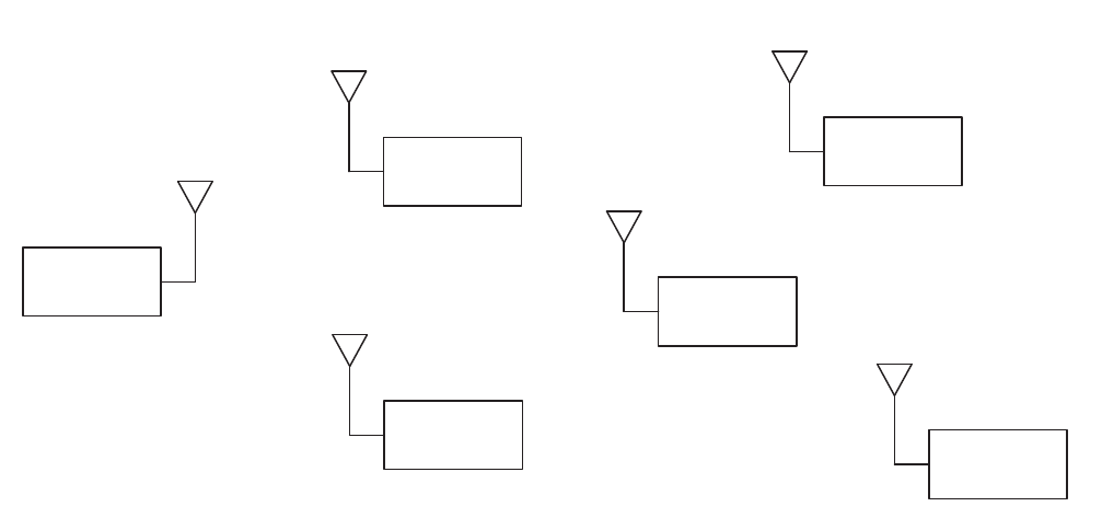
1.0 XDM2140 Introduction
RFM’s XDM2140 is a 2.4 GHz IEEE 802.15.4 radio module designed to provide excellent
communications reliability and long battery life in a wide range of sensor network applications. The
XDM2140 employs DUST Networks’ SmartMesh-XD™ technology which blends the reliability of self-
organizing and self-healing mesh networking with synchronized power duty cycling to achieve very long
battery life operation. The XDM2140 is certified for unlicensed operation in the USA, Canada and
Europe. An example XDM2140 network is shown in Figure 1. The network consists of a Gateway and up
to 250 XDM2140-based Sensor Nodes. The Gateway consists of a SmartMesh-XD™ radio and a single-
board Linux computer. The Gateway includes the XDM2140 network manager function and provides the
application interfaces. The Gateway includes an Ethernet port that supports XML-based network
commands, and two RS232 serial ports that support binary string network commands, diagnostics, etc.
X D M 2 1 4 0 N e t w o r k
N e t w o r k
G a t e w a y X D M 2 1 4 0
S e n s o r
N o d e 3
X D M 2 1 4 0
S e n s o r
N o d e 5
X D M 2 1 4 0
S e n s o r
N o d e 2
X D M 2 1 4 0
S e n s o r
N o d e 4
X D M 2 1 4 0
S e n s o r
N o d e 1
Figure 1
SmartMesh-XD™ traffic is organized in to TDMA frames consisting of 31.25 ms time slots. The Gateway
assigns time slots to each XDM2140 node in the network, and then maintains a precise report interval
(frame-to-frame period) to provide a highly synchronized network. Network operation also hops from
channel to channel in a pseudorandom pattern to mitigate the effects of multipath fading and narrowband
interference. The Gateway monitors performance on each channel and will temporarily discontinue the
use of a channel that is showing poor performance statistics.
Mesh networking allows traffic to be passed from sensor node to sensor node so that messages can be
delivered to and from sensor nodes that can not communicate directly with the Gateway. At least two
paths are maintained by the network for communication between each field node and the Gateway. As
needed, a new paths will be automatically established to replace a failing paths to maintain network
performance.
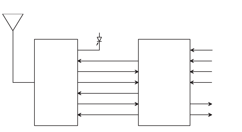
As shown in Figure 2, each sensor node in the network consists of an XDM2140 radio module and a
host microcontroller with sensor I/O electronics. The host microcontroller communicates with the
XDM2140 radio module on a serial interface using binary command and response strings as discussed
in Section 9 of this document.
X D M 2 1 4 0
H o s t
M i c r o c o n t r o l l e r
a n d
S e n s o r
I / O
R X
T X
/ M T _ R T S
/ S P _ C T S
/ M T _ C T S
/ T I M E
T y p i c a l X D M 2 1 4 0 A p p l i c a t i o n
+
/ L E D
A n a l o g
a n d / o r
D i g i t a l
I n p u t s
A n a l o g
a n d / o r
D i g i t a l
O u t p u t s
Figure 2
RFM’s XDM2140 delivers the exceptional network reliability and long battery life capabilities of
SmartMesh-XD™ technology in a fully functional, certified radio module that is easily interfaced to a wide
variety of sensor network applications.

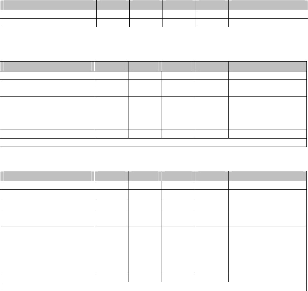
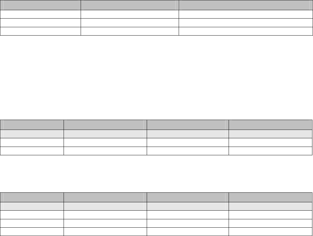
2.0 Absolute Maximum Ratings
The ratings below should not be exceeded under any circumstances. Damage can be caused by exceeding one or more of these
parameters.
Parameter Min Typ Max Units Comments
Supply voltage (V
DD
to V
SS
) -0.3 5.5 V
Voltage on any digital I/O pin -0.3 3.6 V
Input RF level 10 dBm Input power at antenna
connector
Storage temperature range -40 +85 °C
VSWR of antenna 3:1
ESD protection
Antenna pad ±250 V HBM
All other pads ±2 kV HBM
±200 V CDM
* All voltages are referenced to V
SS
.
Caution! This is an ESD sensitive device. Use proper ESD handling procedures when working with the device to prevent
permanent damage.
Table 1
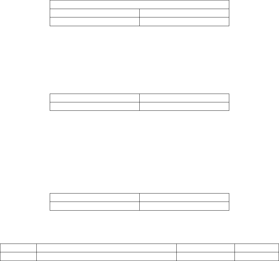
3.0 Normal Operating Conditions
Parameter Min Typ Max Units Comments
Operational supply voltage range
(between V
DD
and V
SS
)
3.3 3.6 5.5 V Including noise and load
regulation
Voltage supply noise 100 mV
p-p
50 Hz to 2 MHz
Operating temperature range -40 +85 °C
Maximum allowed ambient temperature
ramp during operation
8 °C/min -40 °C to +85 °C
Operating relative humidity 10 90 % RH Non-condensing
Unless otherwise noted, V
DD
is 3.6 V and temperature is -40 °C to +85 °C.
Table 2
3.1 Current Consumption
Parameter Min Typ Max Units Comments
Transmit 18 mA
Receive 6 mA
Sleep 8.5 µA
Table 3
4.0 Electrical Specifications
4.1 Device Load
Parameter Min Typ Max Units Comments
Total capacitance 0.5 µF
Total inductance 84 nH
Unless otherwise noted, V
DD
is 3.6 V and temperature is -40 °C to +85 °C.
Table 4
4.2 Digital I/O Type 1
Digital Signal Min Typ Max Units Comments
V
IL
(low-level input voltage) -0.3 0.6 V
V
IH
(high-level input voltage) 0.8 x V
DD
V
DD
+ 0.3 V
V
OL
(low-level output voltage) 0.4 V
V
OH
(high-level output voltage) 2.4 V
Digital current
*
Output source (single pin) 3.7 mA 25 °C
Output sink (single pin) 2.0 mA 25 °C
Input leakage current 50 nA
*
This current level guarantees that the output voltage meets V
OH
and V
OL
specifications above.
Table 5
4.3 Digital I/O Type 2
Digital Signal Min Typ Max Units Comments
V
IL
(low-level input voltage) -0.3 0.6 V
V
IH
(high-level input voltage) 0.8 x V
DD
V
DD
+ 0.3 V
V
OL
(low-level output voltage, multi-function
I/O configured as output)
0 0.6 V I
OL
< 0.6 mA, 85 °C
V
OH
low-level output voltage, multi-function
I/O configured as output)
V
DD
- 0.6 V
DD
V I
OH
> -0.4 mA, 85 °C
Digital current
*
Output source (single pin,
multifunction I/O configured as
output)
0.4 mA 25 °C
Output sink (single pin,
multifunction I/O configured as
output)
0.6 mA 25 °C
Input leakage current 50 nA
*
This current level guarantees that the output voltage meets V
OH
and V
OL
specifications above.
Table 6
5.0 RF Specifications
5.1 Radio Specifications
Parameter Min Typ Max Units Comments
Operating frequency 2.4000 2.4835 GHz
Number of channels 15
Channel separation 5 MHz
Occupied channel bandwidth 2.7 MHz at -20 dBc
Frequency accuracy -50 +50 kHz
Modulation IEEE 802.15.4 DSSS
Raw data rate 250 kb/s
Receiver operating maximum input level 0 dBm
Receiver sensitivity
-92.5 dBm At 50% PER, V
DD
= 3 V,
25 °C
-90 dBm At 1% PER, V
DD
= 3 V,
25 °C, (inferred from 50%
PER measurement)
Output power, conducted
+8 dBm V
DD
= 3 V, 25 °C
Table 7
5.2 Antenna Specifications
The antenna must meet specifications below. When the XDM2140 is placed inside an enclosure, the antenna should be mounted
such that the radiating portion of the antenna protrudes from the enclosure, and connected using a coaxial cable. For optimum
performance, allow the antenna to be positioned vertically when installed. The XDM2140 has been FCC certified as a module with
both a dipole antenna and a patch antenna. Any 2.4 GHz dipole antenna or 2.4 GHz patch antenna with a gain less than or equal
to 12 dBi may be used without the need for any FCC type acceptance testing. If a different antenna type or a higher gain dipole or
patch is to be used, please contact RFM Technical Support for more information.
Antenna Parameter Value
Frequency range 2.4000 - 2.4835 GHz
Impedance 50 ohms
Maximum VSWR 3:1
Table 8

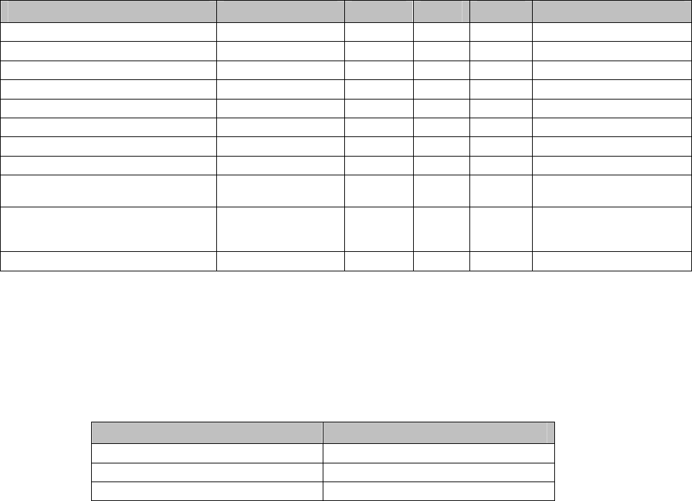
6.0 Module Pinout
Pin Number Pin Name Description
1 GND Connect to the host circuit board ground.
2 NC Leave unconnected.
3 NC Leave unconnected.
4 NC Leave unconnected.
5 UART_TX Serial data output from UART.
6 UART_RX Serial data input from UART.
7 /MT_RTS Active low output to the host signaling the XDM2140 has a packet to
deliver.
8 MODE Mode B input, normally grounded.
9 NC Leave unconnected.
10 /SP_CTS Active low input from the host signaling it is ready to receive a packet.
11 /TIME Active low input to trigger the XDM2140 to send a timestamp packet.
12 /MT_CTS Active low clear to send output from XDM2140 to the host.
13 NC Leave unconnected.
14 VBAT Power supply input, +3.3 to +5.5 Vdc
15 GND Connect to the host circuit board ground.
16 GND Connect to the host circuit board ground.
17 /RESET IN Active low XDM2140 reset input.
18 /LED Active low status LED driver ouput.
19 NC Leave unconnected.
20 NC Leave unconnected.
21 NC Leave unconnected.
22 NC Leave unconnected.
23 NC Leave unconnected.
24 NC Leave unconnected.
25 NC Leave unconnected.
26 NC Leave unconnected.
27 NC Leave unconnected.
28 GND Connect to the host circuit board ground.
29 NC Leave unconnected.
30 GND Connect to the host circuit board ground.
RF Connector U.FL coaxial antenna connector.
Table 9
7.0 Boot Sequence
Following the active low assertion of /RESET IN, the XDM2140 completes its boot-up process by loading
and decrypting the application image and loading the operating parameters. During the boot process, the
modules output signals are not actively driven and the input signals are ignored. The duration of the boot
process is defined in Table 10.
Boot Parameter Min Typ Max Units Comments
t
boot_delay
6 s The time between power up and
serial interface availability
Table 10
8.0 Hardware Interfaces
8.1 /RESET IN
When this signal is asserted low, the XDM2140 is hardware reset until the signal is de-asserted. Note
that the XDM2140 may also be reset using the mote serial command. If a system is designed to assert
/RESET IN after the XDM2140 has completed its boot process, it is recommended the module be placed
into deep sleep prior to assertion of the /RESET IN signal.
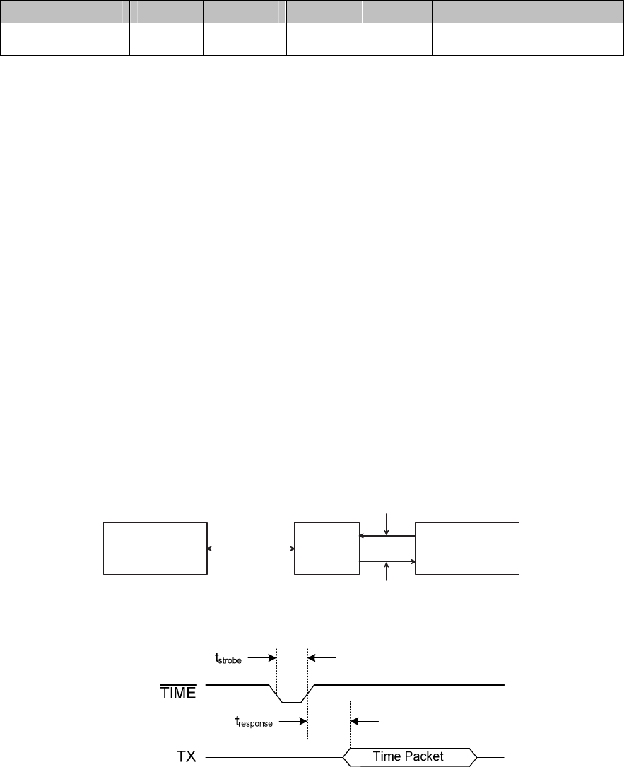
8.2 /TIME
The XDM2140 has the ability to deliver network-wide synchronized timestamps. The XDM2140 sends a
time packet through its serial interface when one of the following occurs:
• HDLC Get Parameter request for time/state is received.
• Active-low /TIME signal is asserted.
Use of the /TIME input is optional but has the advantage of being more accurate. The value of the
timestamp is taken within approximately 1 ms of receiving a /TIME signal assertion. The XDM2140 will
send the time packet ot the local host microcontroller within 100 ms of the strobe. If the HDLC request is
used, due to packet processing the value of the timestamp may be captured several milliseconds after
receipt of the packet. The real time delivered to the sensor processor is relative to the real-time clock on
the Gateway, which serves as the Network Real Time Clock (NRTC). The time stamp skew across the
network is guaranteed to be within ±250 ms of the NRTC.
H o s t
M i c r o c o n t r o l l e r
X D M 2 1 4 0
N e t w o r k
G a t e w a y
/ T I M E P i n o r
H D L C C o m m a n d
T i m e
P a c k e t
R F
N e t w o r k
Figure 3
Figure 4
/TIME Parameters Meaning Min Max Units
t
strobe
TIME strobe pulse width 125 µs
t
response
TIME strobe active low assertion to start of time packet 100 ms
Table 11
8.3 /LED
The XDM2140 provides an output to drive a status LED. This signal indicates network connectivity
information, which is useful during XDM2140 system installation. Alternatively, the XDM2140 status may
be polled using the serial Get Parameter request with the module state parameter.
/LED Signal Behavior Mote State
High Off, or in sleep mode
Single blink (750 ms low, 3 s high) On, and searching for potential network
Double blink (750 ms low, 750 ms high, 750 ms low, 3 s high) On, and attempting to join the network
Triple blink (750 ms low, 750 ms high, 750 ms low, 750 ms high, 750 ms
low, 3 s high)
On, and attempting to establish redundant links
Low On, fully configured into network with redundant parents
Table 12
8.4 Settable I/O Modes
The XDM2140 offers a choice of two I/O modes. The functionality of the interface will be determined by
the setting MODE input.
MODE Pin Setting Mode 1 Mode 3
Setting Externally tied low Externally tied high
Table 13
Both modes provide a means of transmitting and receiving serial data through the wireless network, and
a command interface that provides synchronized time stamping, local configuration and diagnostics.
Mode 1 implements an 8-bit, no parity, 9600 baud, three, four or five-signal serial interface with
bidirectional packet-level flow control operating at 9600 b/s. In certain designs, one or two of the serial
handshake signals may be optional for reduced pin count. Please refer to detailed descriptions of
signals. Mode 3 implements an 8-bit, no parity, 9,600 baud, five-signal serial interface with bidirectional
packet-level flow control and byte-level flow control in the XDM2140-to-microcontroller direction only.
8.4.1 Mode 1 - Three/Four/Five-signal Serial Interface (9600 b/s)
XDM2140 Mode 1 provides a three, four, or five-signal serial interface optimized for low-powered
embedded applications, and in certain designs may provide a lower pin count serial solution. The Mode 1
serial interface comprises the data pins UART_TX and UART_RX, with handshake pins /MT_RTS,
/MT_CTS, /SP_CTS used for bidirectional flow control. The /MT_RTS signal is ideal for designs where
the host microcontroller requires extra time to prepare to receive a packet. For example, when the host
microcontroller sleeps periodically and requires a wake-up signal prior to receiving a packet. Refer to
Table14 for information on each pin, including details on which pins are optional.

Mode 1 Pin Usage
Pin I/O Usage
RX Input Serial data moving from the microcontroller to the XDM2140.
TX Output Serial data moving from the XDM2140 to the microcontroller.
/MT_RTS Output /MT_RTS provides a mechanism to wake up the microcontroller in order to receive a packet. This signal
is asserted when the XDM2140 is ready to send a serial packet. The signal stays low until the /SP_CTS
signal from the microcontroller is detected low by the XDM2140 (indicating readiness to receive a
packet) or the timeout defined in Section 8.4.3 expires. /MT_RTS may be ignored by the microcontroller
only if /SP_CTS always stays low.
/SP_CTS Input /SP_CTS provides packet level flow control for packets transferred from the XDM2140 to the
microcontroller. When the microcontroller is capable of receiving a packet it should assert the /SP_CTS
signal. /SP_CTS may be externally tied low (reducing pin count) only if the microcontroller is always
ready to receive a serial packet.
/MT_CTS Output /MT_CTS provides packet level flow control for packets transferred from the microcontroller to the
XDM2140 that are destined for transfer over the network. Upon reset, following boot the XDM2140 will
negate /MT_CTS until the XDM2140 establishes a wireless network connection. During operation, the
XDM2140 will negate /MT_CTS if the XDM2140 does not have sufficient buffering to accept another
packet. /MT_CST will also remain high if the XDM2140 is not part of the network. The microcontroller
must check that the /MT_CTS pin is low before initiating each serial packet for wireless transmission.
Note that the XDM2140 may receive local serial packets at any time regardless of the /MT_CTS state.
/TIME Input The /TIME pin can be used for triggering a timestamp packet. Its usage is optional.
Table 14
8.4.2 Mode 3 - Five-signal Serial Interface (9600 b/s)
XDM2140 Mode 3 provides a five-signal serial interface with byte-level flow control on transfers from the
XDM2140 to the microcontroller. The Mode 3 serial interface is comprised of the data pins UART_TX
and UART_RX, with handshake pins /MT_RTS, /MT_CTS and /SP_CTS used for bidirectional flow
control. The /MT_RTS signal is ideal for designs where the microcontroller requires extra time to prepare
to receive a packet. For example, the host microcontroller sleeps periodically and requires a wake-up
signal prior to receiving a packet). Refer to Table 15 for information on each handshake pin, including
details on which of those pins are optional.
Mode 3 Pin Usage
Pin I/O Usage
RX Input Serial data moving from the microcontroller to the XDM2140.
TX Output Serial data moving from the XDM2140 to the microcontroller.
/MT_RTS Output /MT_RTS provides a mechanism to wake up the microcontroller in order to receive a packet. This signal
is asserted when the XDM2140 is ready to send a serial packet. The signal stays low until the /SP_CTS
signal from the microcontroller is detected low by the XDM2140 (indicating readiness to receive a
packet) or the t
ack_delay
timeout defined in Section 8.4.3 expires.
/SP_CTS Input /SP_CTS provides both packet and byte level flow control for packets transferred from the XDM2140 to
the microcontroller. When the microcontroller is capable of receiving a packet it should assert the
/SP_CTS signal. In Mode 3, byte-level flow control is achieved by having the microcontroller negate and
then reassert the /SP_CTS signal following the receipt of each byte. The XDM2140 will begin
transmission of the next byte after detecting the reassertion of /SP_CTS.
/MT_CTS Output /MT_CTS provides packet level flow control for packets transferred from the microcontroller to the
XDM2140 that are destined for transfer over the network. Upon reset, following boot the XDM2140 will
negate /MT_CTS until the XDM2140 establishes a wireless network connection. During operation, the
XDM2140 will negate /MT_CTS if the XDM2140 does not have sufficient buffering to accept another
packet. /MT_CTS will also remain high if the XDM2140 is not part of the network. The microcontroller
must check that the /MT_CTS pin is low before initiating each serial packet for wireless transmission.
Note that the XDM2140 may receive local serial packets at any time regardless of the /MT_CTS state.
/TIME Input The /TIME pin can be used for triggering a timestamp packet. Its usage is optional.
Table 15
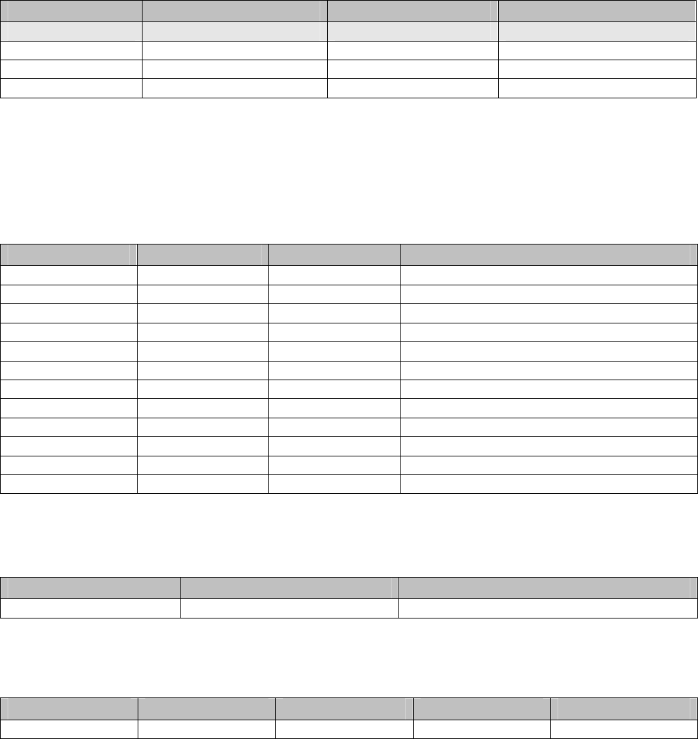
8.4.3 UART Timing Values
Variable Meaning Min Max Units
t
RX_BAUD
Deviation from baud rate -2 +2 %
t
RX_STOP
Number of stop bits 1 bit period
t
TX_BAUD
Deviation from baud rate -1 +1 %
t
TX_STOP
Number of stop bits 1 bit period
t
SP_CTS to MT_RTS
Assertion of /SP_CTS to negation of /MT_RTS 0 10 ms
t
MT_RTS to SP_CTS
Assertion of /MT_RTS to assertion of /SP_CTS 500 ms
t
SP_CTS to TX
Assertion of /SP_CTS to start of byte 0 10 ms
t
TX to SP_CTS
Start of byte to negation of /SP_CTS 1 bit period
t
SP_CTS ack PW
Negation pulse width of /SP_CTS 500 ns
t
diag_ack_timeout
The XDM2140 responds to all requests within this time. 125 ms
t
min_strobe_length
The minimum length of the strobe signals, /TIME and /SP_CTS 500 ns
t
interbyte_timeout
Falling edge of TX to falling edge of /SP_CTS (Mode 3 only) 8 ms
t
interpacket_delay
The sender of an HDLC packet must wait at least this amount of time
before sending another packet
20 ms
t
ack_delay
The max time delay between the /MT-RTS and the receiver’s
acknowledge, /SP_CTS
1 500 ms
t
time_ack_timeout
The XDM2140 responds to all /TIME pin activation requests within this
time
100 ms
Table 16
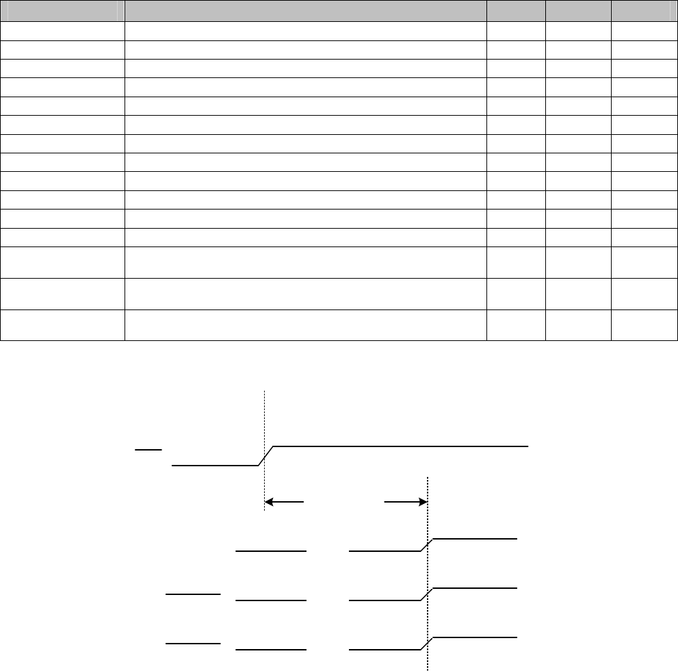
Power-on Sequence
TX HIGH-Z
HIGH-Z
HIGH-Z
tboot_delay
RST
MT_RTS
MT_CTS
Figure 5
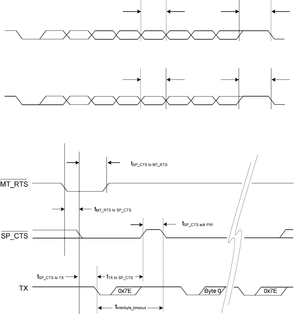
Byte-level Timing
LSB MSB STOP
RX
TX LSB MSB STOP
tRX_BAUD tRX_STOP
tTX_BAUD tTX_STOP
Figure 6
Flow Control Timing
Figure 7
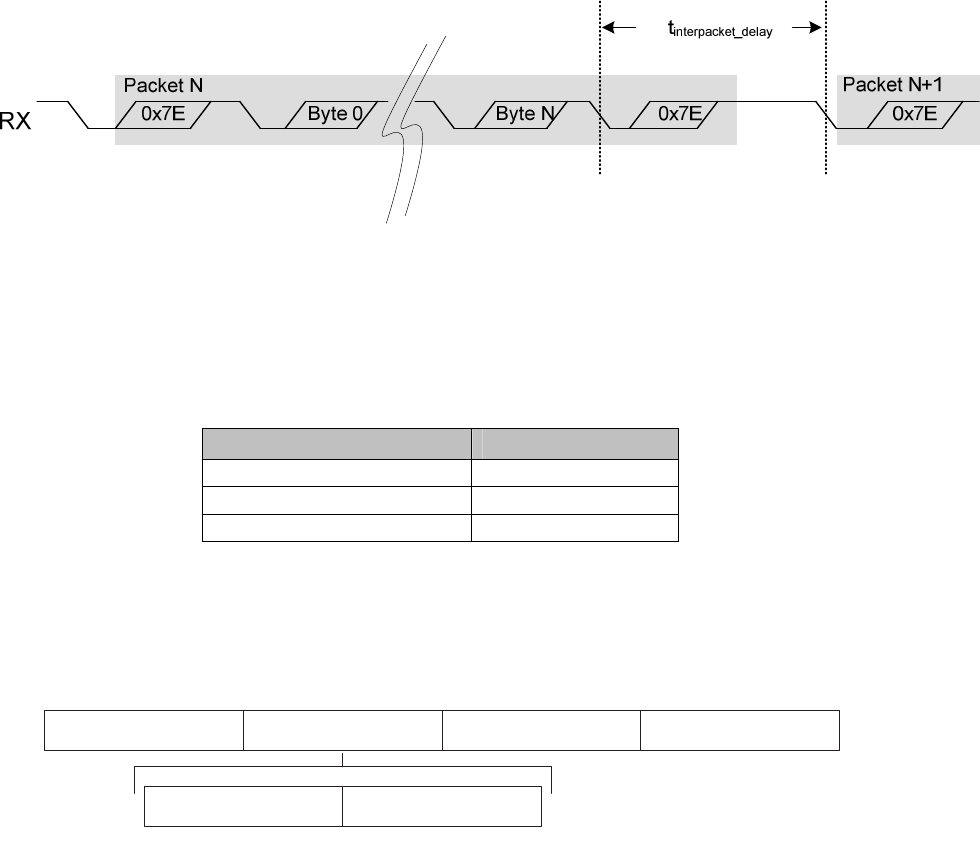
Packet Timing
Figure 8
9.0 Command Set
9.1 Command Data Types
Table 17 below defines the data types used in the commands:
Command Data Types Length
unsigned long 4 bytes
unsigned short 2 bytes
unsigned char 1 bytes
Table 17
9.2 Command Format
X D M 2 1 4 0 C o m m a n d F o r m a t
0 x 7 E 0 x 7 EH D L C C o n t e n t 1 6 - b i t F C S
C o m m a n d T y p e M e s s a g e P a y l o a d
F r a m e S t a r t D e l i m i t e r
( B y t e 0 )
F r a m e D a t a
( B y t e 1 t o B y t e n )
F r a m e C h e c k S e q u e n c e
( B y t e s n + 1 , n + 2 )
F r a m e E n d D e l i m i t e r
( B y t e n + 3 )
C o m m a n d
( B y t e 1 )
P a y l o a d
( B y t e 2 t o B y t e n )
Figure 9
HDLC Packet Structure
The command type indicates which API message is contained in the message payload. The message
payload for each command type is described within the following sections. The length of the message
payload is 80 bytes (excluding byte-stuffing bytes).
The frame checksum (FCS) is calculated based on the 16-bit FCS computation method (FCS-16, RFC
1662). The XDM2140 checks the FCS and drops packets that have FCS errors. All numerical fields in a
packet are in big-endian order (MSB first), unless otherwise noted. Section 9.4 provides an example of
HDLC packet construction and HDLC packet decoding.
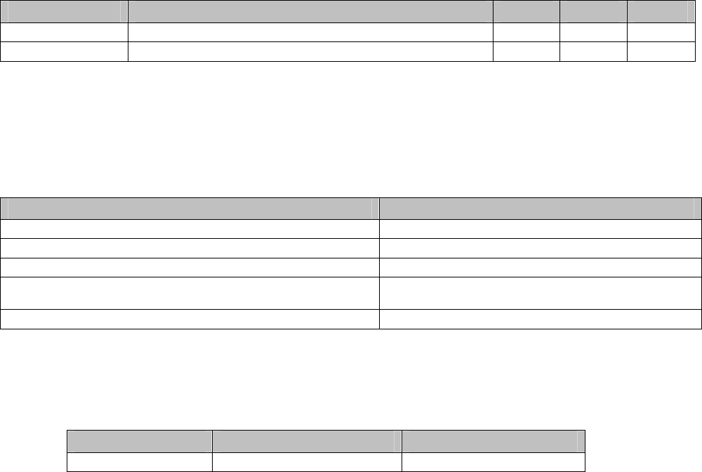
Table 18 provides a summary of XDM2140 commands, which are described in detail in the following
sections. For error handling, all other packet types should be ignored. The Destination column indicates
whether the packet is sent (or received) through the network or processed locally by the XDM2140.

XDM2140 Command Summary
Command Type (HEX) Direction Destination Description
0x80 Microcontroller to XDM2140 Network Packet destined for the network
0x81 XDM2140 to microcontroller Network Unacknowledged packet received from the
network and destined for microcontroller
0x82 XDM2140 to microcontroller Network Acknowledged packet received from the network
and destined for microcontroller
0x83 — — Reserved
0x84 XDM2140 to microcontroller Local Time and XDM2140 state information
0x85 — — Reserved
0x86 — — Reserved
0x87 Microcontroller to XDM2140 Local Set Parameter request
0x88 XDM2140 to microcontroller Local Set Parameter response
0x89 Microcontroller to XDM2140 Local Get Parameter request
0x8A XDM2140 to microcontroller Local Get Parameter response
0x8C XDM2140 to microcontroller Local XDM2140 information
0x8D Microcontroller to XDM2140 Local Reset XDM2140
0x09 Microcontroller to XDM2140 Local Deep sleep
0x0B Microcontroller to XDM2140 Local Test radio transmission
0x0C Microcontroller to XDM2140 Local Test radio reception
0x02 Microcontroller to XDM2140 Local Get radio reception test statistics
Table 18
9.2.1 Command 0x80 - Serial Payload Sent to Serial Port
Serial Data Packets going into the XDM2140 serial port use the command type 0x80. Upon receiving the
packet, the XDM2140 forwards it to the network. The format of the serial packet payload is transparent to
the XDM2140. There is no response by the XDM2140 upon reception of this command.
Command 0x80 Format Details
Message Byte Description Data Type Request (Sent to XDM2140)
1 Command type unsigned char 0x80
2 (Transparent to XDM2140) First byte of data
...2+n (Transparent to XDM2140) Up to n–1 additional bytes of data
Table 19
9.2.2 Command 0x81 - Unacknowledged Serial Payload Received from Serial Port
Unacknowledged serial data packets going out of the XDM2140 serial port use command type 0x81. The
network uses this command to send data out through the XDM2140 serial interface. Upon receiving this
packet from the network, the XDM2140 forwards it to the microcontroller without sending
acknowledgement to the Gateway. The format of the serial packet payload is transparent to the
XDM2140. The maximum length of the message payload is defined in Section 9.2.

Command 0x81 Format Details
Message Byte Description Data Type Value
1 Command type unsigned char 0x81
2 (Transparent to XDM2140) First byte of data
...2+n (Transparent to XDM2140) Up to n–1 additional bytes of data
Table 19
9.2.3 Command 0x82 - Acknowledged Serial Payload Received from Serial Port
Acknowledged serial data packets going out of the XDM2140 use command type 0x82. The network
uses this command to send data out through the XDM2140 serial interface. Upon receiving this packet
from the network, the XDM2140 forwards it to the microcontroller and sends an acknowledgement back
to the Gateway. The format of the serial packet payload is transparent to the XDM2140. The maximum
length of the message payload is defined in Section 9.2. The microcontroller receives exactly one copy
of the message that was sent through the network.
Command 0x82 Format Details
Message Byte Description Data Type Value
1 Command type unsigned char 0x82
2 (Transparent to XDM2140) First byte of data
...2+n (Transparent to XDM2140) Up to n–1 additional bytes of data
Table 20
9.2.4 Command 0x84 - Time/State Packet
Time data packets use the command type 0x84. The time packet includes the network time and the
current real time relative to the Gateway. The XDM2140 sends this response when the /TIME pin is
strobed high to low for minimum of t
min_strobe_length
, as defined in Section 8.4.3. The data returned is
identical to that returned in response to the Get parameter request with time as the parameter.
Command 0x84 Format Details
Message Byte Description Data Type Value
1 Command type unsigned char 0x84
2-5 The sequential number of the
frame
unsigned long Cycle
6-9 The offset from start of frame unsigned long Offset (µs)
10-11 Frame length unsigned short Frame length (slots)
12-15 UTC time unsigned long Real time part 1 (s)
16-19 UTC time unsigned long Real time part 2 (µs)
20-23 Time from the last XDM2140 reset
unsigned long XDM2140 uptime (s)
24 XDM2140 state unsigned char XDM2140 state
25 XDM2140 diagnostics status unsigned char XDM2140 diagnostics status
Table 21

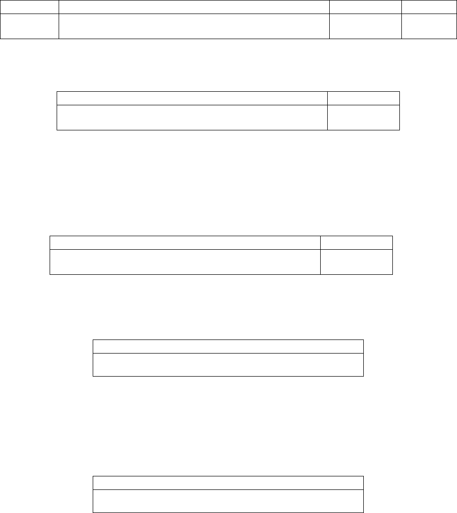
9.2.5 Commands 0x87 and 0x88 - Set Parameter Request/Response
The Set Parameter command allows the setting of a number of configuration parameters in the
XDM2140. When the Set Parameter Request command is sent, the response to the request is sent
within the diag_ack_timeout . The command structure for individual Parameter Types and can be found
in Section 9.3. The length of payload (n) is dependant on the Parameter type.
Command 0x87 Format Details
Message Byte Description Data Type Value
1 Command type unsigned char 0x87
2 Parameter type unsigned char Parameter type (see Section 9.3)
3 Data First byte of data
...3+n Data Up to n-1 additional bytes of data
Table 22
Response 0x88 Format Details
Message Byte Description Data Type Value
1 Command type unsigned char 0x88
2 Parameter type unsigned char
Parameter type (see Section 9.3)
3 Error code unsigned char Error code
4 Data length unsigned char 0x00
Table 23
9.2.6 Commands 0x89 and 0x8A - Get Parameter Request/Response
The Get Parameter command allows a number of configuration parameters in the XDM2140 to be read
by the serial port. When a Get Parameter Request command is sent, the response to the request is sent
within the diag_ack_timeout. The command structure for individual parameter types can be found in
Section 9.3. The length of payload (n) depends on the parameter type. If the error code is not equal to
zero, no data is returned in the response. Error codes are described in Table 38.
Command 0x89 Format Details
Message Byte Description Data Type Value
1 Command type unsigned char 0x89
2 Parameter type unsigned char Parameter type (see Section 9.3)
3 Data First byte of data
...3+n Data Up to n-1 additional bytes of data
Table 24
Response 0x8A Format Details
Message Byte Description Data Type Value
1 Command type unsigned char 0x8A
2 Parameter type unsigned char Parameter type (see Section 9.3)
3 Error code unsigned char Error code (see Table 38)
4 Data length unsigned char n
5 Data First byte of data
...5+n Data Up to n-1 additional bytes of data
Table 25

9.2.7 Command 0x8C - XDM2140 Information
The XDM2140 sends this packet after boot_delaly following a power-up reset to supply information about
the XDM2140 properties.
Command 0x8C Format Details
Message Byte Description Data Type Value
1 Command type unsigned char 0x8C
2-4 HW model Array of 3 unsigned char Byte 1 = 0x41
Byte 2 = 0x05 to 0x0F
Byte 3 = 0x01
5-6 HW revision Array of 2 unsigned char HW revision
7-10 SW revision Array of 4 unsigned char SW revision
11-18 MAC address Array of 8 unsigned char MAC addr
19 Networking type unsigned char 0x04
20-21 Network ID unsigned short Network ID
22-29 Datasheet ID Array of 8 unsigned char 000_0002
30-31 XDM2140 ID unsigned short XDM2140 ID
32 Reserved
33 XDM2140 diagnostics status unsigned char XDM2140 diagnostics status
Table 26
9.2.8 Command 0x8D - Reset XDM2140
Upon receiving this command, the XDM2140 notifies its neighbors about an upcoming reset, and then
proceeds to reset itself. The delay to the actual reset depends on the network configuration.
Command 0x8D Format Details
Message Byte Description Data Type Value
1 Command type unsigned char 0x8D
Table 27
9.2.9 Command 0x09 - Deep Sleep
The Deep Sleep command will put the XDM2140 into a non-functional, lowest-power consumption state
with current draw on the order of a few microamps. Deep sleep is ideal when the XDM2140 is connected
to its power source, but must be stored for extended periods. The XDM2140 will enter deep sleep within
2 seconds after receiving the Deep Sleep command. The XDM2140 will wake from deep sleep when
either the /RESET IN pin is asserted and then de-asserted, or the XDM2140 is power cycled.
Command 0x09 Format Details
Message Byte Description Data Type Value
1 Command type unsigned char 0x09
2 Payload length unsigned char 0x00
3 Flags unsigned char 0x00 (request packet)
Table 28
Response 0x09 Format Details
Message Byte Description Data Type Value
1 Command type unsigned char 0x09
2 Payload length unsigned char 0x00
3 Flags unsigned char 0x01 (response packet)
4 Response code unsigned char 0x00 (OK)
Table 29
9.3 Get/Set Command Parameters
This section specifies the parameters that may be used with the Get and Set Commands. Table 35
provides an overview of these parameters.
Get/Set Command Parameters
Parameter Type Set Parameter Get Parameter Description
0x01 X Set the XDM2140’s network ID
0x02 X Get the XDM2140’s current network connection state
0x03 X Get the network frame length
0x04 X Set the network join key on the XDM2140
0x05 X Get the network time and XDM2140 state information
0x06 Reserved
0x07 X Get the XDM2140’s properties
0x08 X X Set/get the power amplifier mode
0x09 Reserved
0x0A X Get the XDM2140’s charge consumption
0x0B X X Set/get the XDM2140 power source value
0x0C X X Put XDM2140 into RF testing mode
Table 30
All requests have the following structure.
Request Structure for Parameter Data Packets
Command Type Parameter Type Data (Optional)
1 byte 1 byte Up to 33 bytes
Table 31
All replies have the following structure.
Reply Structure for Parameter Data Packets
Command Type Parameter Type Error Code Data Length Data (Optional)
1 byte 1 byte 1 byte 1 byte Up to 31 bytes
Table 32
Command Types, Parameter types, and error codes are discussed in the following sections. Data length
is the number of bytes of following data, set to 0 in case of non-zero error code.
9.3.1 Error Codes
Error Codes are listed in Table 38 below.
Error Code Details
Number Error Description
0 DIAG_NO_ERR No command-specific errors
1 DIAG_EXE_ERR XDM2140 unable to execute command
2 DIAG_PARAM_ERR Illegal parameter in the request
Table 33
9.3.2 Parameter Type 0x01 - Network ID
The network ID is the identification number used to distinguish different wireless networks. In order to
join a specific network, the XDM2140 must have the same network ID as the network Gateway. This
parameter is only valid for the Set Parameter command. Upon receiving this request, the XDM2140
stores the new network ID in its persistent storage area, but continues to use the existing network ID.
The XDM2140 must be reset in order to begin using the new network ID.
Parameter Type 0x01 Set Request Details
Message Byte Description Data Type Value
1 Command type unsigned char 0x87
2 Parameter type unsigned char 0x01
3-4 Network ID unsigned char Network ID
Table 34
The following packet is sent in response to a request to set the network ID.
Parameter Type 0x01 Set Response Details
Message Byte Description Data Type Value
1 Command type unsigned char 0x88
2 Parameter type unsigned char 0x01
3 Error code unsigned char Error code
4 Data length unsigned char 0x00
Table 35
9.3.3 Parameter Type 0x02 - XDM2140 State
This parameter is only valid for the Get Parameter command and is used to retrieve the XDM2140’s
current network connection state.

Parameter Type 0x02 Get Request Details
Message Byte Description Data Type Value
1 Command type unsigned char 0x89
2 Parameter type unsigned char 0x02
Table 36
The following packet is sent in response to a request to retrieve the XDM2140’s current network
connection state.
Parameter Type 0x02 Get Response Details
Message Byte Description Data Type Value
1 Command type unsigned char 0x8A
2 Parameter type unsigned char 0x02
3 Error code unsigned char Error code
4 Data length unsigned char 0x02
5 XDM2140 state unsigned char XDM2140 state
6 XDM2140 diagnostics status unsigned char XDM2140 diagnostics status
Table 37
XDM2140 States
State Number Description Details
1 ACTIVE The XDM2140 has joined the network and is waiting to be
configured.
2 JOINING The XDM2140 has sent a join request and is waiting to be
activated.
3 ACT SEARCH The XDM2140 is actively searching for neighbors.
4-5 PASS SEARCH The XDM2140 is passively searching for neighbors.
6 SYNCHRONIZED The XDM2140 is synchronized to a network, listening in
active search.
7-8 RESETTING The XDM2140 is going through the reset process.
9 ONLINE1 The XDM2140 has joined a network and is fully
configured, but has only one parent. The XDM2140 is
ready to transmit data to the network.
10 ONLINE2 The XDM2140 has joined a network, is fully configured,
and has multiple parents. The XDM2140 is ready to
transmit data to the network.
Table 38
Diagnostics Status
Bit Description Details
7 — Reserved
6 — Reserved
5 — Reserved
4 — Reserved
3 — Reserved
2 — Reserved
1 CCF Configuration change flag (see Section 9.3.3.1)
0 NV_ERR Non-volatile memory error
Table 39

9.3.3.1 Configuration Change Flag (CCF)
The Configuration Change Flag (CCF) bit is set high when the network ID is changed. Note that when
the network ID is changed over the air (using the XML-API), the entire network synchronously changes
over to the new network ID. There is no delay between when the XML-API command is received and
when XDM2140 changes over to the new network ID. The CCF bit is set high when the new network ID
becomes active. The CCF bit is cleared when the XDM2140 receives a XDM2140 Information Get
request (Command 0x07), a getParameter Time command, a getParameter XDM2140 State command,
or the XDM2140 is reset.
9.3.4 Parameter Type 0x03 - Frame Length
This parameter is only valid for the Get Parameter command and is used to retrieve the frame length of
the specified frame ID.
Parameter Type 0x03 Get Request Details
Message Byte Description Data Type Value
1 Command type unsigned char 0x89
2 Parameter type unsigned char 0x03
3 Frame ID unsigned char Frame ID
Table 40
The following packet is sent in response to a request to retrieve the frame length.
Parameter Type 0x03 Get Response Details
Message Byte Description Data Type Value
1 Command type unsigned char 0x8A
2 Parameter type unsigned char 0x03
3 Error code unsigned char Error code
4 Data length unsigned char 0x05
5 Frame ID unsigned char Frame ID
6-9 Frame length unsigned long Frame length (µs)
Table 41
9.3.5 Parameter Type 0x04 - Join Key
The join key is needed to allow a XDM2140 on the network. The join key is specific for the network and
used for data encryption. This parameter is only valid for a Set Parameter command. Upon receiving this
request, the XDM2140 stores the new join key in its persistent storage. The XDM2140 must be reset in
order to begin using the new join key.
Parameter Type 0x04 Set Request Details
Message Byte Description Data Type Value
1 Command type unsigned char 0x87
2 Parameter type unsigned char 0x04
3-18 New join key Array of 16 unsigned char New join key
Table 42
The following packet is sent in response to a request to set the join key.

Parameter Type 0x04 Set Response Details
Message Byte Description Data Type Value
1 Command type unsigned char 0x88
2 Parameter type unsigned char 0x04
3 Error code unsigned char Error code
4 Data length unsigned char 0x00
Table 43
9.3.6 Parameter Type 0x05 - Time/State
This parameter is only valid for the Get Parameter command and is used to request the network time
and XDM2140 state information. The response to this command returns the same information as
Command 0x84 (Time/State Packet), with the only difference being that this command can be solicited
using the Get command, rather than a hardware pin.
Parameter Type 0x05 Get Request Details
Message Byte Description Data Type Value
1 Command type unsigned char 0x89
2 Parameter type unsigned char 0x05
Table 44
The following packet is sent in response to a request for the network time and XDM2140 state
information.
Parameter Type 0x05 Get Response Details
Message Byte Description Data Type Value
1 Command type unsigned char 0x8A
2 Parameter type unsigned char 0x05
3 Error code unsigned char Error code (see 0)
4 Data length unsigned char 0x18
5-8
The sequential number of frame
unsigned long Cycle
9-12 The offset from start of frame unsigned long Offset (µs)
13-14 Frame length unsigned short Frame length (slots)
15-18 UTC time unsigned long Real time part 1 (s)
19-22 UTC time unsigned long Real time part 2 (µs)
23-26 Time from the last XDM2140 reset unsigned long XDM2140 uptime (s)
27 XDM2140 state unsigned char XDM2140 state
28 XDM2140 diagnostics status unsigned char XDM2140 diagnostics status
Table 45
9.3.7 Parameter Type 0x07 - XDM2140 Information
This parameter is only valid for the Get Parameter command. It is a local request (a packet that is not
sent through the network) that retrieves information about the XDM2140’s properties.
Parameter Type 0x07 Get Request Details
Message Byte Description Data Type Value
1 Command type unsigned char 0x89
2 Parameter type unsigned char 0x07
Table 46

The following packet is sent in response to a request for information about XDM2140 properties
Parameter Type 0x07 Get Response Details
Message Byte Description Data Type Value
1 Command type unsigned char 140 (0x8A)
2 Parameter type unsigned char 0x07
3 Error code unsigned char Error code
4 Data length unsigned char Data length (0x20)
5-7 HW model Array of 3 unsigned char Byte 1 = 0x41
Byte 2 = 0x05 to 0x0F
Byte 3 = 0x01
8-9 HW revision Array of 2 unsigned char HW revision
10-13 SW revision Array of 4 unsigned char SW revision
14-21 MAC address Array of 8 unsigned char MAC address
22 Networking type unsigned char 0x04
23-24 Network ID unsigned short Network ID
25-32 Datasheet ID Array of 8 unsigned char 000_0002
33-34 XDM2140 ID unsigned short XDM2140 ID
35 Reserved
36 XDM2140 diagnostics status unsigned char XDM2140 diagnostics status
Table 47
9.3.8 Parameter Type 0x08 Power Amplifier
This parameter is valid for both the Set Parameter and Get Parameter commands. As a Set Parameter, it
sets the power amplifier mode (on/off) on the XDM2140. As a Get Parameter, it retrieves the current
power amplifier mode on the XDM2140.
Parameter Type 0x08 Set Request Details
Message Byte Description Data Type Value
1 Command type unsigned char 0x87
2 Parameter type unsigned char 0x08
3 Power amplifier mode unsigned char 0x00 = Turns off power amplifier
0x01 = Turns on power amplifier
Table 48
Parameter Type 0x08 Set Response Details
Message Byte Description Data Type Value
1 Command type unsigned char 0x88
2 Parameter type unsigned char 0x08
3 Error code unsigned char 0x00 = No error
0x01 = Execution error
0x02 = Command format error
Table 49

Parameter Type 0x08 Get Request Details
Message Byte Description Data Type Value
1 Command type unsigned char 0x89
2 Parameter type unsigned char 0x08
Table 50
Parameter Type 0x08 Get Response Details
Message Byte Description Data Type Value
1 Command type unsigned char 0x8A
2 Parameter type unsigned char 0x08
3 Error code unsigned char 0x00 = No error
0x01 = Execution error
0x02 = Command format error
4 Data length unsigned char 0x01
5 Power amplifier mode unsigned char 0x00 = Power amplifier is off
0x01 = Power amplifier is on
Table 51
9.3.9 Parameter Type 0x0A - Charge Consumption
This parameter is only valid for the Get Parameter command. It retrieves the charge the XDM2140 has
consumed since the last reset, the XDM2140 uptime, and XDM2140 temperature.
Parameter Type 0x0A Get Request Details
Message Byte Description Data Type Value
1 Command type unsigned char 0x89
2 Parameter type unsigned char 0x0A
Table 52
The following packet is sent in response to a request for information about the XDM2140 charge
consumption, XDM2140 uptime, and XDM2140 temperature.
Parameter Type 0x0A Get Response Details
Message Byte Description Data Type Value
1 Command type unsigned char 140 (0x8A)
2 Parameter type unsigned char 0x0A
3 Error code unsigned char Error code
4 Data length unsigned char Data length (0x0E)
5-8 Charge since last reset unsigned long Charge (mC)
9-12 Uptime since last reset unsigned long Uptime (s)
13-14 Temperature unsigned short Temperature (°C)
15-18 Reserved unsigned long Reserved
Table 53

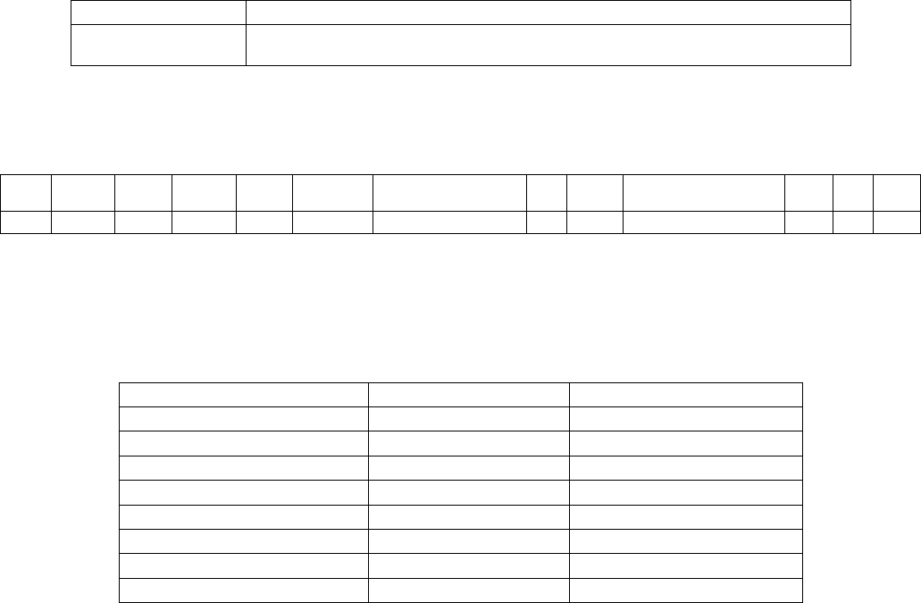
9.3.10 Parameter Type 0x0B - Power Source
This command allows the user to set and get the power source configuration of the XDM2140. These
values are sent to the Gateway and are taken in consideration during link allocation. When a XDM2140
is designated as low power, the XDM2140 will operate in an ultra low-power state. When in this state, the
XDM2140 will not advertise for neighbors, and the Gateway will not assign children to the XDM2140.
This parameter is valid for both the Set Parameter and Get Parameter commands. Upon receiving this
request, the XDM2140 stores the new setting in its persistent storage. The XDM2140 must be reset in
order to begin using the new setting.
Parameter Type 0x0B Set Request Details
Message Byte Description Data Type Value
1 Command type unsigned char 0x87
2 Parameter type unsigned char 0x0B
3 Power source unsigned char 0x00 = powered
0x01 = AA L91
0x03 = low power
0x0F = unknown
Table 54
Parameter Type 0x0B Set Response Details
Message Byte Description Data Type Value
1 Command type unsigned char 0x88
2 Parameter type unsigned char 0x0B
3 Error code unsigned char Error code
4 Data length unsigned char 0x00
Table 55
Parameter Type 0x0B Power Source Get Request Details
Message Byte Description Data Type Value
1 Command type unsigned char 0x89
2 Parameter type unsigned char 0x0B
Table 56
Parameter Type 0x0B Get Response Details
Message Byte Description Data Type Value
1 Command type unsigned char 0x8A
2 Parameter type unsigned char 0x0B
3 Error code unsigned char Error code
4 Data length unsigned char 0x01
5 Power source unsigned char 0x00 = powered
0x01 = AA L91
0x03 = low power
0x0F = unknown
Table 57
9.4 HDLC Packet Examples
Example 1: Constructing an HDLC packet to send to the XDM2140
This example demonstrates how you would construct an HDLC packet to set the network ID value to 00
7D. (All values are in hexadecimal.)
Step 1 Define HDLC packet payload:
Command type => 87
Parameter => 01
Network ID => 00 7D
HDLC Packet Payload
Command Type Message Content
87 01 00 7D
Table 58
Step 2 Calculate FCS:
• Calculate the FCS using FCS-16 algorithm (RFC 1662) on the hexadecimal sequence '87
01 00 7D'.
The FCS (including 1's complement) is 74 2F.
• Append FCS to payload, FCS is sent least significant byte first (RFC 1662):
HDLC Packet Payload FCS
87 01 00 7D 2F 74
Table 59
Step 3 Perform byte stuffing:
To perform byte stuffing, check the HDLC Packet Payload and FCS for instances of “7D” or
“7E” and replace as follows:
7D => 7D 5D
7E => 7D 5E
Note that the additional control bytes do not count against the message payload limit defined
in Section 9.2.
HDLC Packet Payload (stuffed) FCS (stuffed)
87 01 00 7D 5D 2F 74
Table 60
Step 4 Add start and stop delimiters:
Enclose the above in start/stop flags (RFC 1662).
Start Byte HDLC Packet Payload (stuffed) FCS (stuffed) Stop Byte
7E 87 01 00 7D 5D 2F 74 7E
Table 61
Or simply, the hexadecimal sequence:
7E 87 01 00 7D 5D 2F 74 7E
Example 2: Decoding an HDLC packet received from the XDM2140
To understand how to decode an HDLC packet sent from the XDM2140, let us assume that
the XDM2140 received a Get command with a parameter of XDM2140 information (see
Section 9.3.7), and replied with the following HDLC Packet. (All values are in hexadecimal.)
Start Byte HDLC Packet Payload (stuffed) FCS (stuffed) Stop Byte
7E 8A 07 00 20 00 00 5B 00 01 01 06 00 3C 00 00 00 00 00 00 7D 5E C3
02 00 08 30 30 30 5F 45 56 30 31 00 13 00 00
3E 30
7E
Table 62
Step 1 (HDLC layer) strip off delimiters:
HDLC Packet Payload (stuffed) FCS (stuffed)
8A 07 00 20 00 00 5B 00 01 01 06 00 3C 00 00 00 00 00 00 7D 5E C3
02 00 08 30 30 30 5F 45 56 30 31 00 13 00 00
3E 30
Table 63
Step 2 Remove byte stuffing:
To remove byte stuffing, check for instances of “7D 5D” or “7D 5E” and replace as follows:
7D 5D => 7D
7D 5E => 7E
HDLC Packet Payload FCS
8A 07 00 20 00 00 5B 00 01 01 06 00 3C 00 00 00 00 00 00 7E C3 02 00
08 30 30 30 5F 45 56 30 31 00 13 00 00
3E 30
Table 64
Step 3 Confirm FCS:
Calculate the checksum for the HDLC payload.
HDLC Packet Payload
8A 07 00 20 00 00 5B 00 01 01 06 00 3C 00 00 00 00 00 00 7E C3 02 00
08 30 30 30 5F 45 56 30 31 00 13 00 00
Table 65
Confirm that the FCS matches the FCS sent with the packet. Because the packet encodes
FCS least significant byte first, in this example the calculated FCS should match “30 3E”.
Step 4 (Application layer) parse HDLC payload content:
The resulting packet payload is as follows:
HDLC Packet Payload
8A 07 00 20 00 00 5B 00 01 01 06 00 3C 00 00 00 00 00 00 7E C3 02 00
08 30 30 30 5F 45 56 30 31 00 13 00 00
Table 66
or
Command Type Message Content
8A 07 00 20 00 00 5B 00 01 01 06 00 3C 00 00 00 00 00 00 7E C3 02 00 08 30 30 30 5F 45 56
30 31 00 13 00 00
Table 67
As described in Section 9.3.7, an 0x8A command with parameter type 0x07 has the
following message content structure:
Param
Error
Code
Length HW
Model
HW Rev
SW Rev MAC HW
Type
Net ID Datasheet ID HW ID
Rsvd
Status
07 00 20 00 00 5B
00 01 01 06 00 3C
00 00 00 00 00 00 7E C3 02 00 08
30 30 30 5F 45 56 30 31
00 13 00 00
Table 68
This is a XDM2140 information response with no errors. and a payload length of 32 bytes.
The XDM2140 information is as follows (this is an example; actual values will vary, see
Section 9.3.7).
HW Model 00091 (00 00 5B)
HW Revision 001 (00 01)
SW Revision 1.6.60 (01 06 00 3C)
MAC Address 00 00 00 00 00 00 7E 3C
HW (XDM2140) Type 02 = 2.4 GHz (02)
Network ID 8 (00 08)
Datasheet ID 000_EV01 (30 30 30 5F 45 56 30 31)
HW (XDM2140) ID 19 (00 13)
XDM2140 Diagnostics Status 0 (00)
Table 69
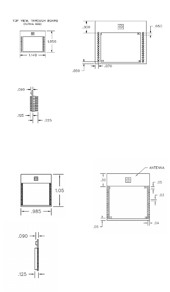
10.0 XDM2140 Outline Drawings
10.1 XDM2140P Pinned Configuration
Figure 9
10.2 XDM2140C Castellated Pad Configuration
Figure 10
SmartMesh-XD™ and mesh-to-the-edge™ are trademarks of DUST Networks, Inc.