Murata Electronics North America ZN241 NETWORK RADIO LINK User Manual USERS MANUAL
Murata Electronics North America NETWORK RADIO LINK USERS MANUAL
USERS MANUAL

5015 B.U. Bowman Drive Buford, GA 30518 USA Voice: 770-831-8048 Fax: 770-831-8598
FCC Part 15.247 Certification
Test Report
FCC ID: HSW-ZN241
FCC Rule Part: 15.247
ACS Report Number: 05-0173-15C
Manufacturer: Cirronet Inc.
Model: ZN241
Manual / Installation Guide
5373 Oakbrook Pkwy
Norcross, GA 30093
(678) 684-2000 main
(678) 684-2001 fax
www.cirronet.com
ZN-241
Base/Remote
Radio Network
Product Manual
for
Installers
Important Regulatory Information
Cirronet Product FCC ID: HSW-ZN241
IC 4492A-ZN241
Note: This unit has been tested and found to comply with the limits for a Class A digital
device, pursuant to part 15 of the FCC Rules. These limits are designed to provide
reasonable protection against harmful interference when the equipment is operated in a
commercial environment. This equipment generates, uses, and can radiate radio
frequency energy and, if not installed and used in accordance with the instruction manual,
may cause harmful interference to radio communications. Operation of this equipment in
a residential area is likely to cause harmful interference in which case the user will be
required to correct the interference at their expense.
Information to user/installer regarding FCC s Maximum Permissible Exposure (MPE)
limits.
NOTE: THE MANUFACTURER IS NOT RESPONSIBLE FOR ANY RADIO OR TV INTERFERENCE
CAUSED BY UNAUTHORIZED MODIFICATIONS TO THIS EQUIPMENT. SUCH MODIFICATIONS
COULD VOID THE USER’S AUTHORITY TO OPERATE THE EQUIPMENT.
FCC s MPE Requirements
Information to user/installer regarding FCC s Maximum Permissible Exposure (MPE) limits.
Notice to users/installers using the following mobile antennas, with Cirronet RF products:
ZN241 5 dBi and 2 dBi Omni Antennas
The field strength radiated by any one of these antennas, when connected to Cirronet RF
products, may exceed FCC mandated RF exposure limits. FCC rules require professional
installation of these antennas in such a way that the general public will not be closer than
20 cm from the radiating aperture of any of these antennas. End users of these systems
must also be informed that RF exposure limits may be exceeded if personnel come closer
than 20 cm to the apertures of any of these antennas.
Getting Started
The ZN241 Radio network is designed for Point of Service (POS) transactions. The
network consists of a server (ZN241-S) and many clients (ZN241-C). Both models use
the same hardware with different software. One option for the server is two antenna
outputs provided by a 2-way splitter with each output 3 dBm lower in RF power.
The ZN241 utilizes a Zigbee standard hardware module. The software is Cirronet’s
networking POS system.
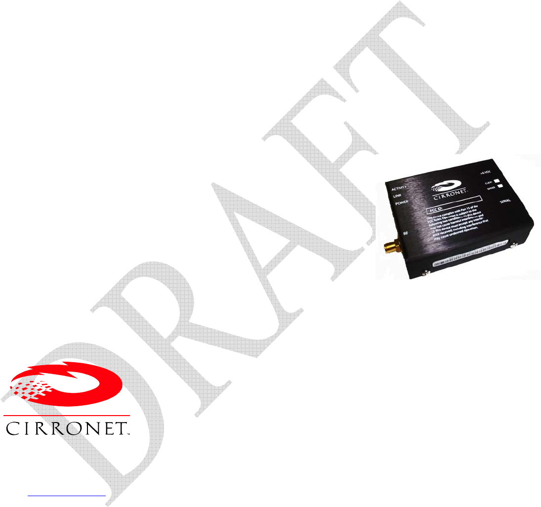
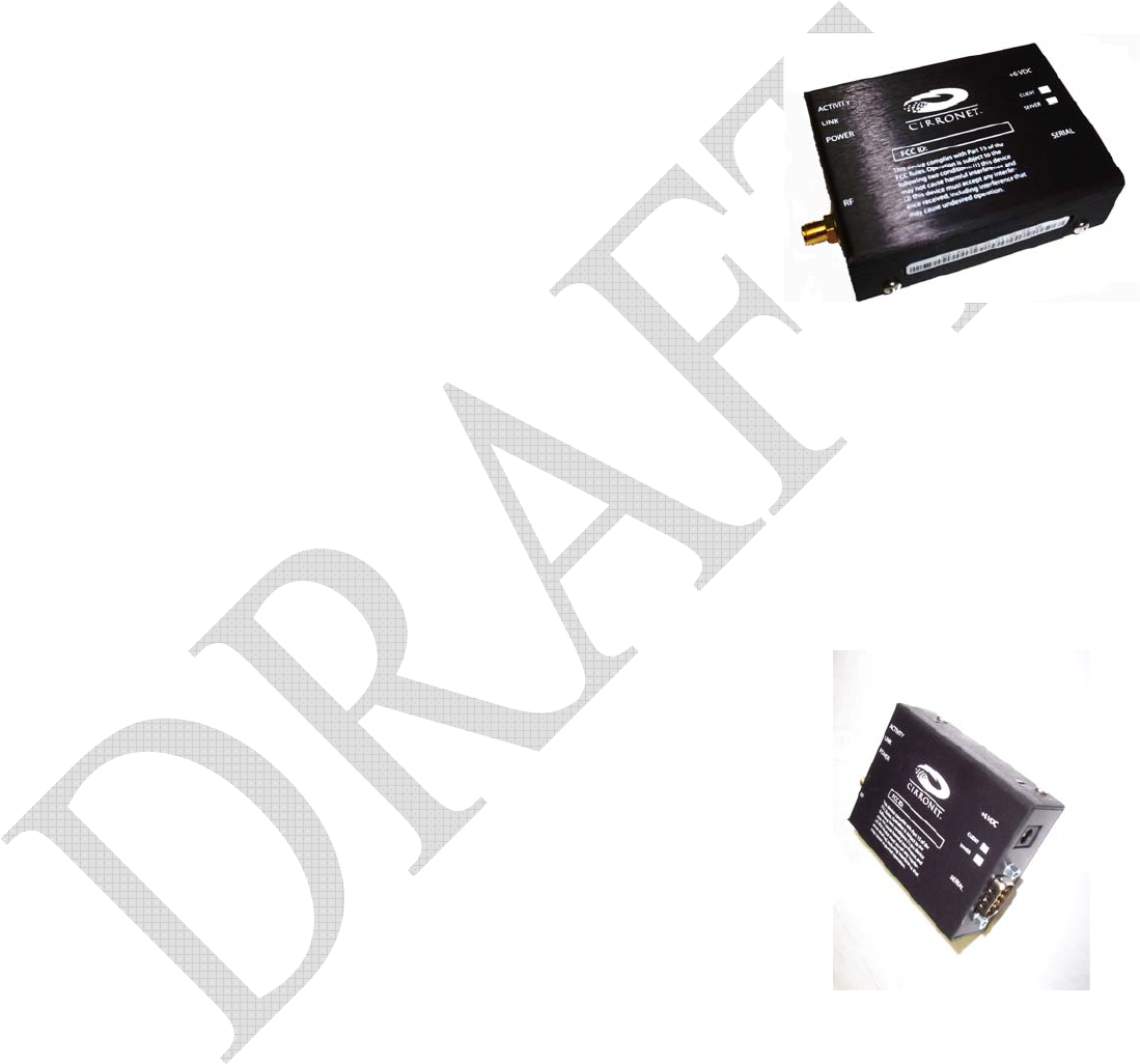
The ZN241 has the following connections:
The antenna connector (RF) is located on the left side of the case, as shown above.
The RS232 and 6 Volt DC connection is on the right side of the case.
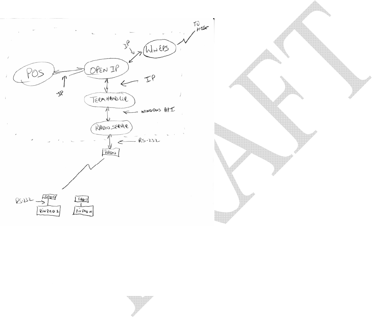
Figure 1 -- ZN241/Hypercom System Block Diagram
Frequency Selection
The ZMN2400 is not frequency agile during run-time, but it can select an
unoccupied portion of the spectrum at startup from among the choices
programmed into the Channel Mask. We believe the most likely source of
interference would be from nearby 802.11b access points, which typically
default to one of the following three channels:
802.11 Channel Center Frequency (MHz)
Nominal Occupied BW
1 2412
2401-2423
6 2437
2426-2448
11 2462
2451-2473
ZigBee defines channel centers from 2405 to 2480 with 5 MHz spacing.
Our strategy is to balance between keeping the number of possible
channels as few as possible (to minimize variation from power-up to
power-up) and to avoid possible 802.11b interferers. With this in mind,
we can select three channels, one at 2480, completely above the three most
common 802.11b channels, and two at the nulls between channels at 2425
and 2480:
ZigBee Channel Center Frequency (MHz)
Nominal Occupied BW
15 2425
2422.5-2427.5
20 2450
2447.5-2452.5
26 2480
2477.5-2482.5
The channels in the 2.4 GHz band span from 11 to 26. Only these
channels are supported by the ZMN2400.
Hardware Specifications
Radio Specifications
Operating Band 2400-2483.5 MHz
Radio Type Direct Sequence (DTS), IEEE
802.15.4 PHY layer
Channel Bit Rate 250 Kbps
Channel Chipping Rate 2 Mcps
Modulation MSK with Raised Cosine
Filtering
Certification Type DTS device per FCC 15.247 and
ETS 300-328
RF power +17 dBm typical, +15 dBm
minimum
Receiver Sensitivity -98 dBm typical, -95 dBm minimum
Link Margin 110 dB (approximately 3 Km
Line of Sight propagation)
Adjacent Ch. Rejection >39 dB with jammer @ 5 MHz
offset
Spurious Output Per FCC 15.247 and ETS 300-328
General
Input Voltage 5.5 volts minimum, 6 volts nominal,
15 volts maximum
Current Consumption 70 mA typical operating, 180 mA peak
(transmit)
Operating Temp Range -40 C to + 70 C
Humidity 95% Non-condensing
RF Connector Reverse SMA
Host Connector Male DB-9 (Amp 747840-3)
Power Connector CUI Stack PJ-002A
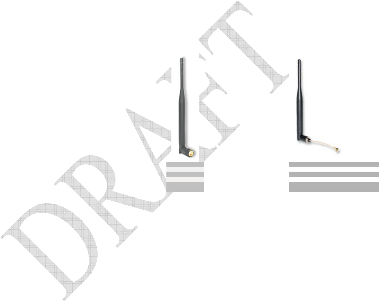
Approved Antennas
5 dBi Collinear – Nearson Antennas
Colinear
Nearson
Server
<<<<<
S-151AH-2450S
Client
>>>>>
S-151FL-36-AH-2450
Colinear
5 dBi 5 dBi
7" 7"
SMA SMA
R/A
Swivel
Right Angle Straight
Swivel