Murata ABF wifi module User Manual SD8787 User Guide
Murata Manufacturing Co., Ltd. wifi module SD8787 User Guide
Murata >
Manual

CMWC1ZZABF EVK User Guide
Author: Kenichi Shibano
Version: 1.0
Release Date: July 13, 2012
CMWC1ZZAAF/ABF
User Guide
CMWC1ZZABF EVK User Guide
CHANGE HISTORY
Version
Date
Remarks
Name
1.0
2012-7-13
Release V1.0;
Shibano
CMWC1ZZABF EVK User Guide
This document explains how to control Murata CMWC1ZZAAF.
1. Module introduction
CMWC1ZZAAF, CMWC1ZZABF is a hostless wifi module which integrate wifi drvier and
TCP/IP stack.
The operation temperature is -20~+75degree.
2. Operation Manual
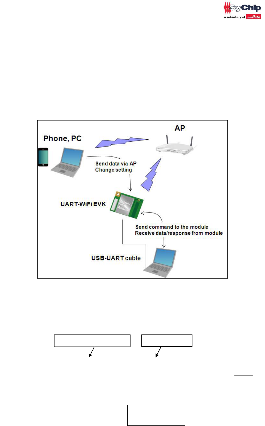
EVK set up is shown in figure1.
Figure1
<Set up>
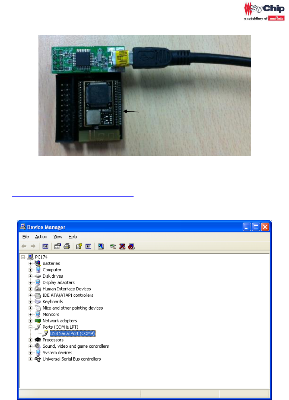
1. Connect EVK and PC through USB cable
Type AAF
UART WiFi module
UART-USB converter board
USB cable to PC
PC
CMWC1ZZABF EVK User Guide
2. Install USB-UART converter driver (FTDI D2xx driver). Customer can download from below
website.
http://www.ftdichip.com/Drivers/D2XX.htm
3. Please open device manager. Customer can see USB Serial Port if driver install is succeeded.
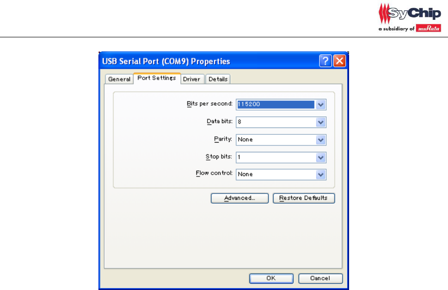
4. Please open properties of USB serial port and change port setting as below.
CMWC1ZZABF EVK User Guide
CMWC1ZZABF EVK User Guide
Page 6 of 17
5. Please open UART communication tool on PC such as hyper terminal. And use same port
setting as 4.
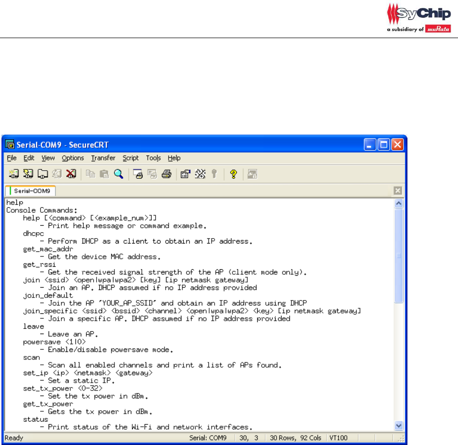
After connection is done, enter “help”, then module responds console command list. Customer can
refer to command list and change setting by themselves.
CMWC1ZZABF EVK User Guide
Page 7 of 17
<Sample application 1> Module control by console mode and webpage
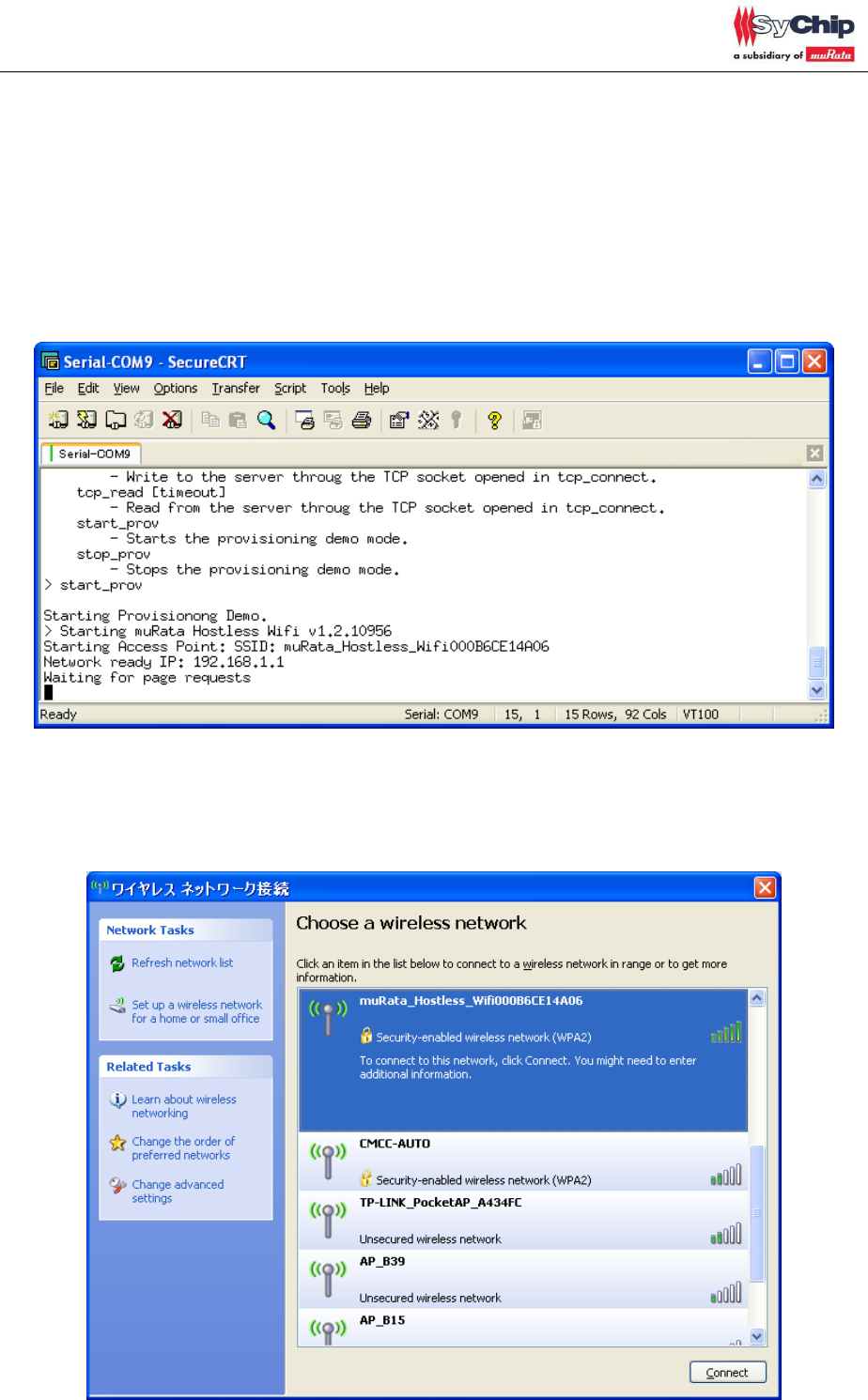
1. If customer enters “start_prov”, EVK starts default access point(AP) mode setting.
SSID: muRata_Hostless_Wifixxxxxxxxxxxx, xxxxxxxxxxxx is EVK mac address
Security: none
DHCP: available
IP address: 192.168.1.1
If customer wants to change setting by themselves, pls enter “stop_prov”.
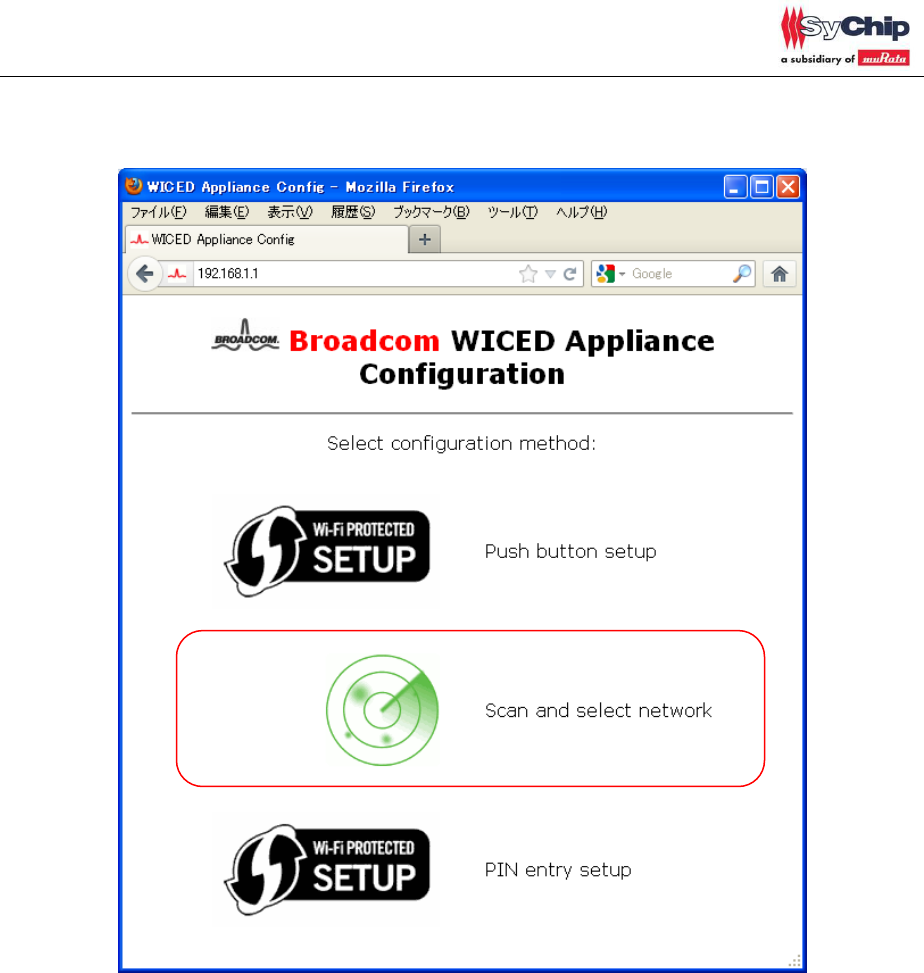
2. Customer can connect EVK from WiFi client(PC or smartphone, etc). Password is 12345678.
CMWC1ZZABF EVK User Guide
Page 8 of 17
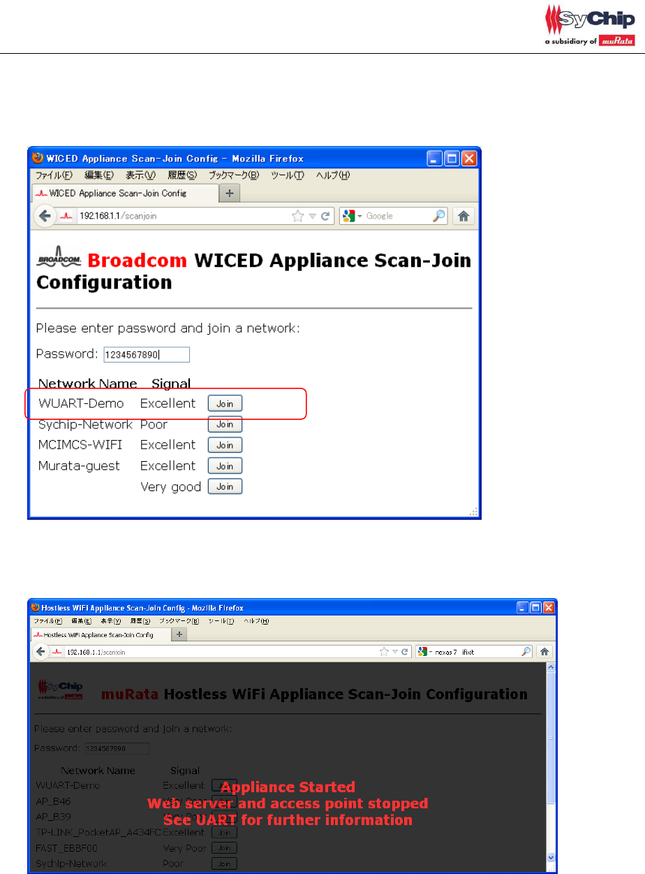
3. Customer can access webpage inside EVK. And change EVK setting to connect with other AP.
URL: 192.168.1.1
Click “Scan and select network”.
CMWC1ZZABF EVK User Guide
Page 9 of 17
4. Join AP network. Join “WUART-Demo” in this document, password is “1234567890”
First, please enter AP password then click “join”. In actual case, customer can select any AP.
After you joined WiFi network, EVK is not in AP mode and changed to client, so EVK and WiFi
client will be disconnected.
CMWC1ZZABF EVK User Guide
Page 10 of 17
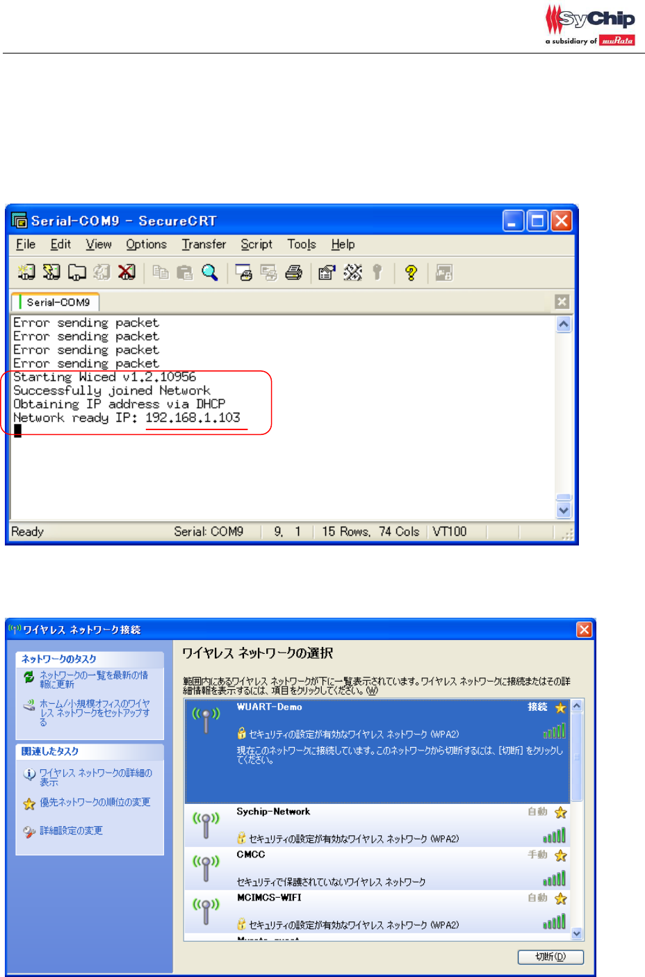
5. You will see attached message from UART port after joined network after joined AP.
EVK connects to AP now then EVK becomes client mode.
EVK owns IP: 192.168.1.103 in this document. (Different IP address may be assigned in actual
case, please confirm IP address.)
Customer can check IP address at EVK through AP’s setting webpage too.
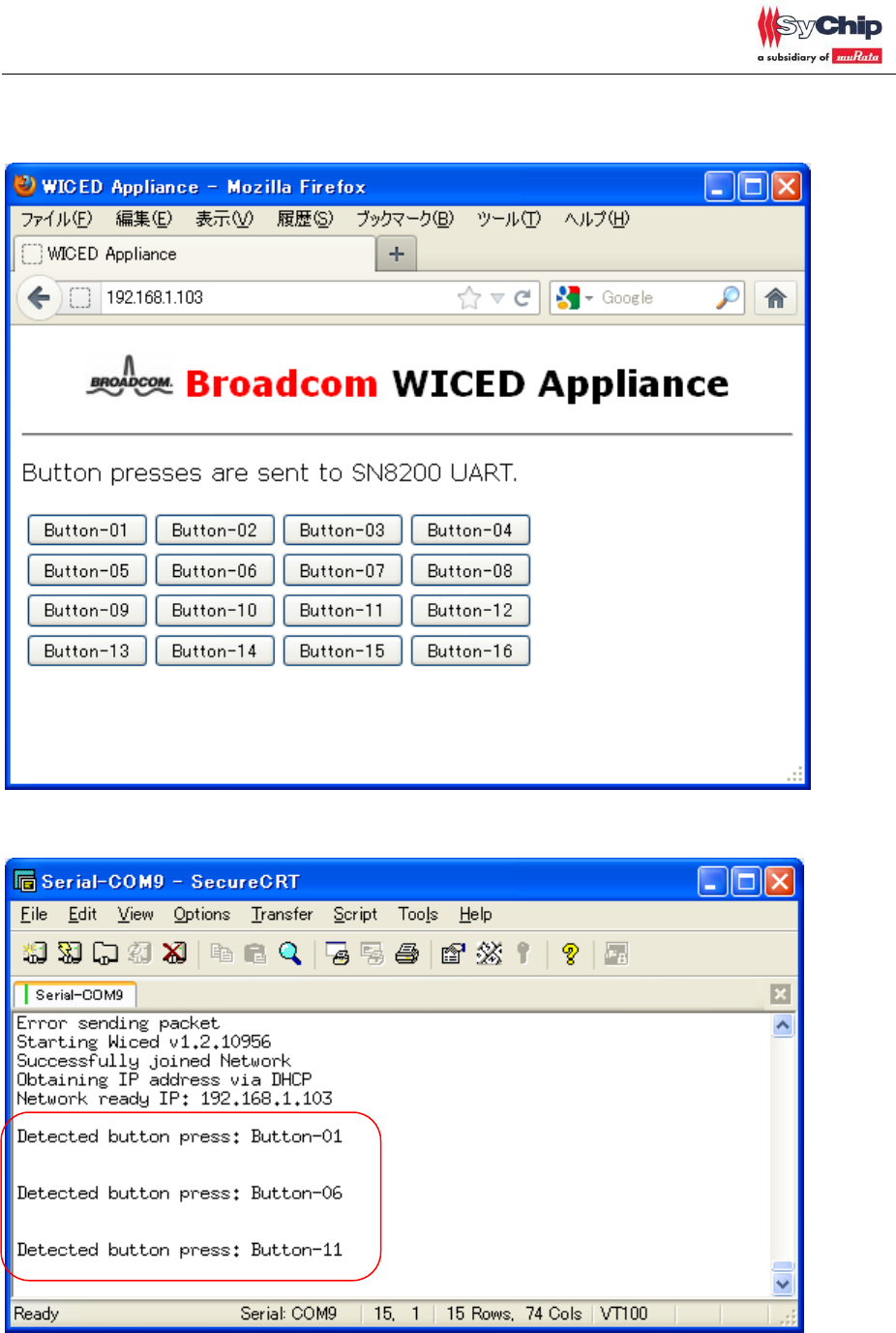
6. Connect to same AP with EVK(WUART-Demo) from other client(ex. PC),
CMWC1ZZABF EVK User Guide
Page 11 of 17
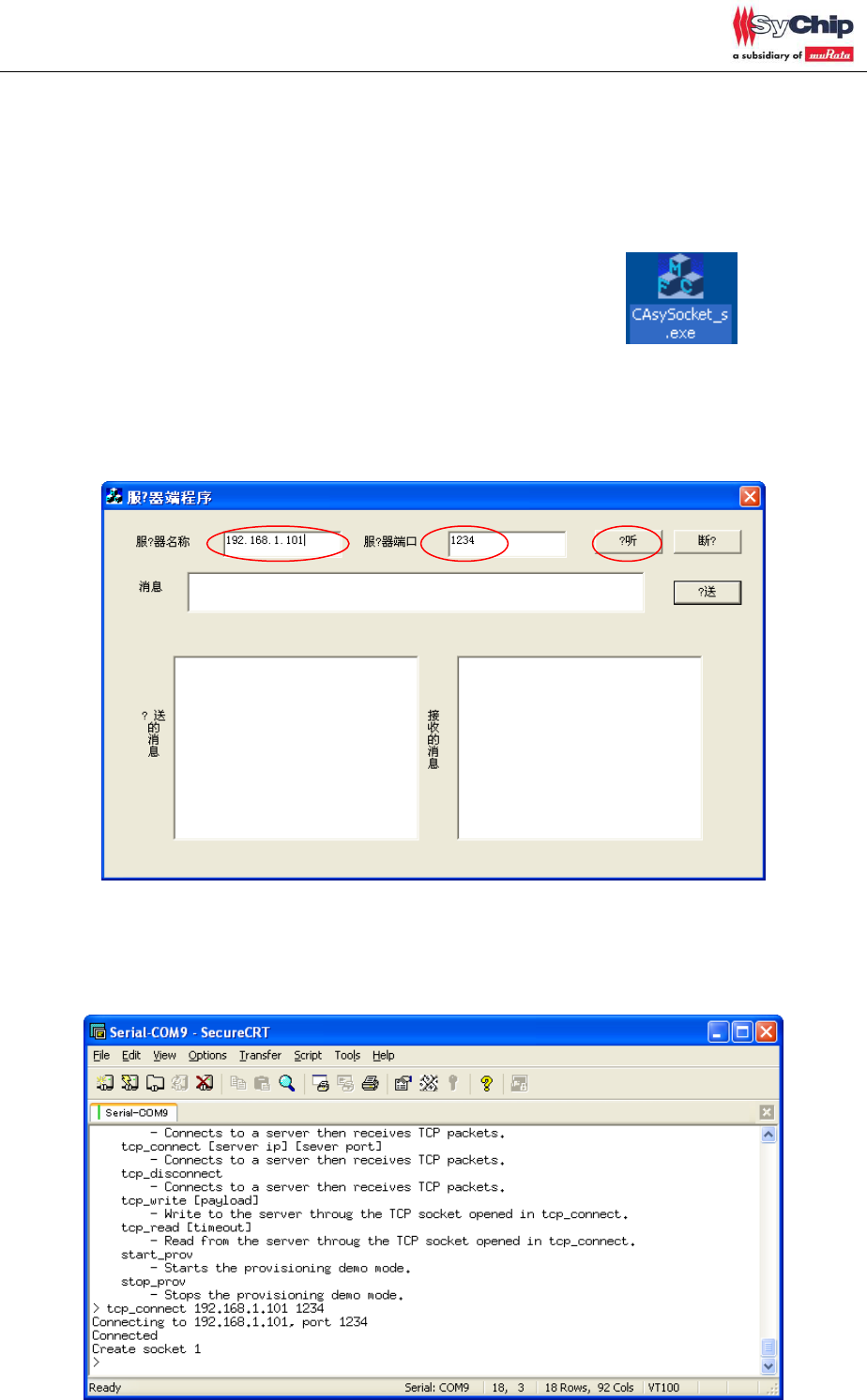
7. Access 192.168.1.103 and you will see attached web page.
Click any button then you will see received message from UART.
CMWC1ZZABF EVK User Guide
Page 12 of 17
<Sample application 2> TCP Server – Client demo
0. Please follow same procedure as <sample application 1>,
8. Connect to same AP with EVK(WUART-Demo) from other client(ex. PC),
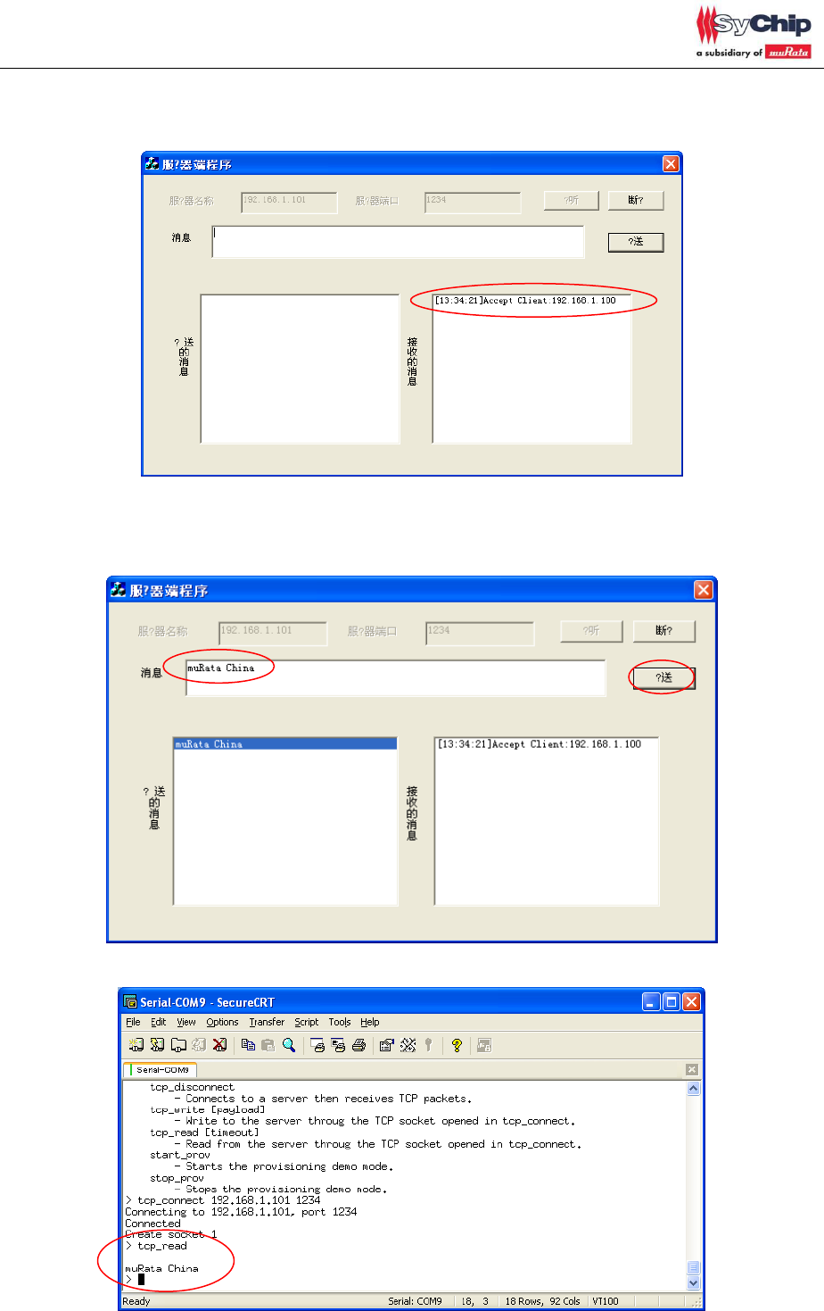
1. Murata provides TCP server-client demo tool. (CAsySocket_s.exe)
Please open the .exe file and you will see below GUI.
2. Please enter PC side IP address, it’s 192.168.1.101 in this document and please input server
port number in random(1234 in this document). And click 接听
3. Please send tcp_connect to EVK.
tcp_connect [server ip] [sever port],
server ip and server port should be same as the one which you enter into CAsySocket_s.
CMWC1ZZABF EVK User Guide
Page 13 of 17
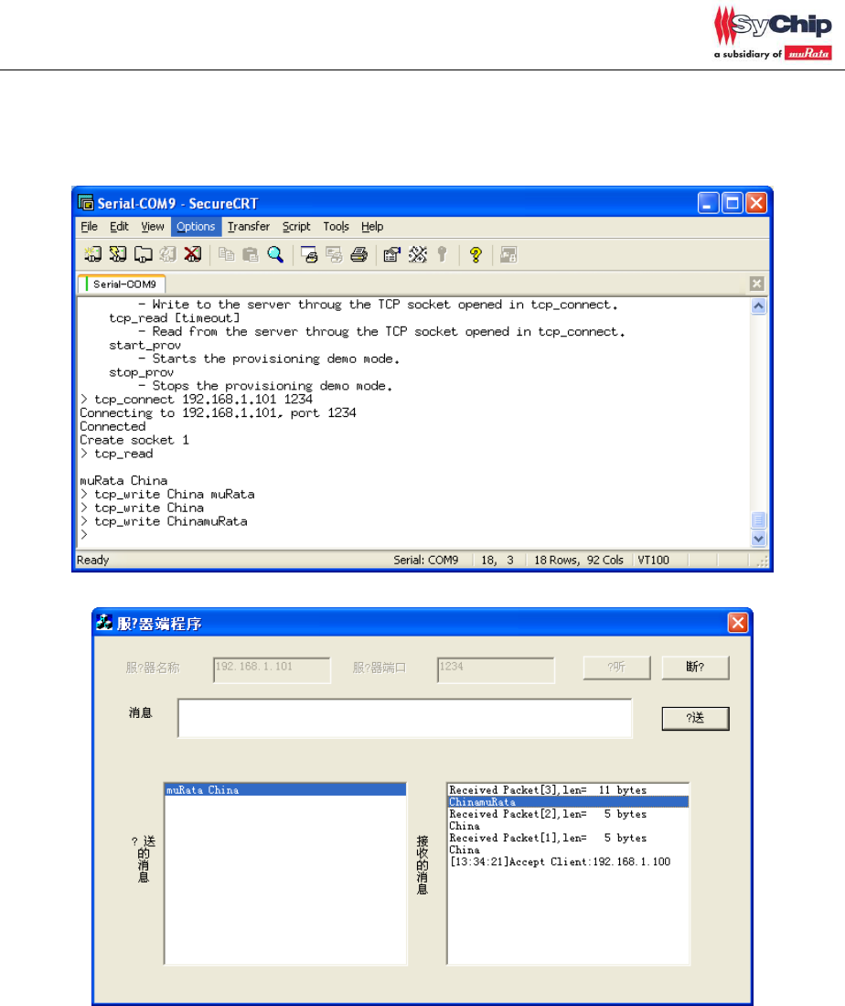
4. After connection success, CAsySocket_s receives the packet from EVK via WiFi AP.
5. Customer can receive packet from server to EVK via AP.
This case, enter “muRata China” then click 发送 button in CAsySocket_s.
Then customer can check EVK received packed by “tcp_read”
CMWC1ZZABF EVK User Guide
Page 14 of 17
6. Customer can send packet from EVK to server.

CMWC1ZZABF EVK User Guide
Page 15 of 17
<Appendix>
Console Commands:
help [<command> [<example_num>]]
- Print help message or command example.
dhcpc
- Perform DHCP as a client to obtain an IP address.
get_mac_addr
- Get the device MAC address.
get_rssi
- Get the received signal strength of the AP (client mode only).
join <ssid> <open|wpa|wpa2> [key] [ip netmask gateway]
- Join an AP. DHCP assumed if no IP address provided
join_default
- Join the AP 'YOUR_AP_SSID' and obtain an IP address using DHCP
join_specific <ssid> <bssid> <channel> <open|wpa|wpa2> <key> [ip netmask gateway]
- Join a specific AP. DHCP assumed if no IP address provided
leave
- Leave an AP.
powersave <1|0>
- Enable/disable powersave mode.
scan
- Scan all enabled channels and print a list of APs found.
set_ip <ip> <netmask> <gateway>
- Set a static IP.
set_tx_power <0-32>
- Set the tx power in dBm.
get_tx_power
- Gets the tx power in dBm.
status
- Print status of the Wi-Fi and network interfaces.
start_ap <ssid> <open|wpa|wpa2> <key> <channel>
- Start AP mode.
stop_ap
- Stop AP mode.
wifi_on
- Turn Wi-Fi device on.
wifi_off
- Turn Wi-Fi device off.
wifi_reset
- Reset the Wi-Fi device.
antenna <0|1|3>
- Antenna selection. 3 = Auto
set_country <country code>

CMWC1ZZABF EVK User Guide
Page 16 of 17
- Set country.
ping <destination>
- Pings the specified IP or Host.
start_dhcpd
- Starts a DHCP daemon.
stop_dhcpd
- Stops the DHCP daemon.
get_random
- Get a random number.
join_wps <pbc|pin> [pin] [<ip> <netmask> <gateway>]
- Join an AP using WPS
tcp_test_tx_server
- Waits for connection then sends TCP packets.
tcp_test_rx_server
- Waits for connection then receives TCP packets.
tcp_test_tx_client [server ip]
- Connects to a server then sends TCP packets.
tcp_test_rx_client [server ip]
- Connects to a server then receives TCP packets.
tcp_connect [server ip] [sever port]
- Connects to a server then receives TCP packets.
tcp_disconnect
- Connects to a server then receives TCP packets.
tcp_write [payload]
- Write to the server throug the TCP socket opened in tcp_connect.
tcp_read [timeout]
- Read from the server throug the TCP socket opened in tcp_connect.
start_prov
- Starts the provisioning demo mode.
stop_prov
- Stops the provisioning demo mode.
Statement
This equipment has been tested and found to comply with the limits for a Class B digital
device, pursuant to Part 15 of the FCC Rules. These limits are designed to provide
reasonable protection against harmful interference in a residential installation. This
equipment generates, uses and can radiate radio frequency energy and, if not installed
and used in accordance with the instructions, may cause harmful interference to radio
communications. However, there is no guarantee that interference will not occur in a
particular installation. If this equipment does cause harmful interference to radio or
television reception, which can be determined by turning the equipment off and on, the

CMWC1ZZABF EVK User Guide
Page 17 of 17
user is encouraged to try to correct the interference by one or more of the following
measures: Reorient or relocate the receiving antenna; Increase the separation
between the equipment and receiver; Connect the equipment into an outlet on a circuit
different from that to which the receiver is connected; Consult the dealer or an
experienced radio/TV technician for help.
In accordance with FCC Part 15C, this module is listed as a Limited Modular
Transmitter device.
Therefore, the final host product must be submitted to [Sychip] for confirmation that the
installation of the module into the host is in compliance with the regulations of FCC and
IC Canada. Specifically, if an antenna other than the model documented in the Filing is
used, a Class 2 Permissive Change must be filed with the FCC.
Changes or modifications not expressly approved by the manufacturer could void the
user’s authority to operate the equipment.
FCC Label Instructions
The outside of final products that contains this module device must display a label
referring to the enclosed module. This exterior label can use wording such as the
following: “Contains Transmitter Module FCC ID: [VPYABF]” or “Contains FCC ID:
[VPYABF].” Any similar wording that expresses the same meaning may be used.
To satisfy FCC RF Exposure requirements for mobile and base station transmission
devices, a separation distance of 20 cm or more should be maintained between the
antenna of this device and persons during operation. To ensure compliance,
operation at closer than this distance is not recommended. The antenna(s) used for
this transmitter must not be co-located or operating in conjunction with any other
antenna or transmitter.
For final installation :
Only the antenna shown in the filing may be used
If the final device is made available to non-professional users, then the antenna must
either be inside the host device enclosure, or changing the antenna must be made
impossible by using a glue which will make it necessary to break the antenna connector
when trying to remove it.
End of document