Murata LB1EN Communication Module User Manual
Murata Manufacturing Co., Ltd. Communication Module
Murata >
Contents
User manual

Dell Edge Gateway
5000 Series
Installation and Operation Manual
Computer Model: Dell Edge Gateway 5000
Regulatory Model: N01G
Regulatory Type: N01G001

Notes, cautions, and warnings
NOTE: A NOTE indicates important information that helps you make better
use of your computer.
CAUTION: A CAUTION indicates either potential damage to hardware or loss
of data and tells you how to avoid the problem.
WARNING: A WARNING indicates a potential for property damage, personal
injury, or death.
Copyright © 2015 Dell Inc. All rights reserved. This product is protected by U.S. and
international copyright and intellectual property laws. Dell™ and the Dell logo are trademarks
of Dell Inc. in the United States and/or other jurisdictions. All other marks and names
mentioned herein may be trademarks of their respective companies.
2015 - 11
Rev. A00
Contents
Overview....................................................................................... 4
System Features........................................................................... 5
System LED Lights..............................................................................................7
Setting up your Dell Edge Gateway..........................................9
Professional installation instructions.................................................................9
Instructions d'installation professionnelles.....................................................10
Federal Communication Commission Interference Statement.....................10
Industry Canada Statement..............................................................................11
Powering on the system.................................................................................. 13
Inserting a micro-SIM card..............................................................................14
Removing the micro-SIM card........................................................................ 15
Setting up your operating system.......................................... 16
Windows 10......................................................................................................16
Ubuntu..............................................................................................................16
Wind River Linux...............................................................................................16
Specifications............................................................................. 17
Contacting Dell..........................................................................20
3

Overview
The Dell Edge Gateway 5000 series allows you to connect (wired or wireless)
to network enabled devices and manage them remotely in your existing
network ecosystem. The system can be either mounted on the wall using the
Dell approved VESA wall mount kit or mounted into your existing rack
infrastructure using the Rail mount. The system is running on Windows 10,
Ubuntu, and Wind River Linux operating systems.
4

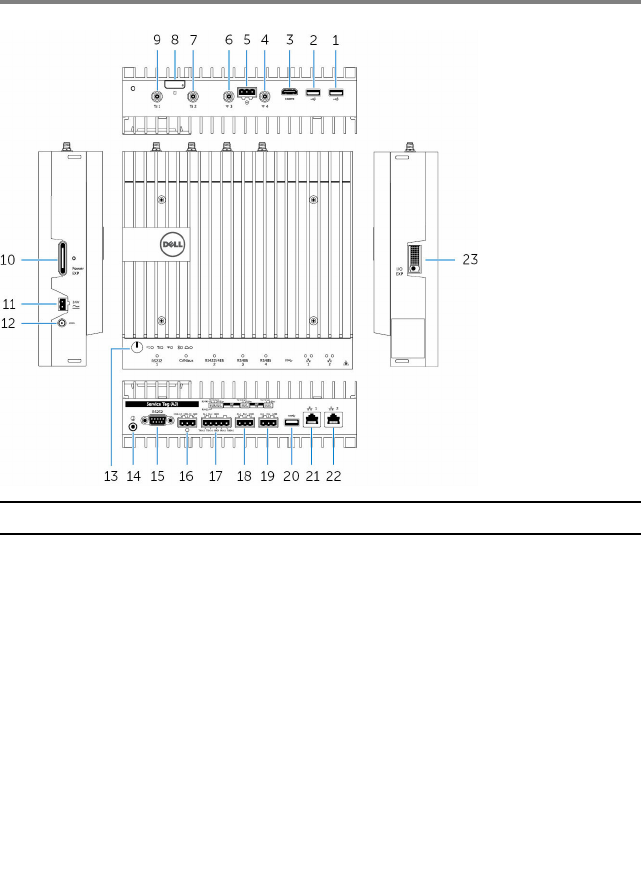
System Features
Feature
1. USB 2.0 port Connect peripherals such as storage
devices, printers, displays and so on.
Provides data transfer speeds up to 480
Mbps.
2. USB 2.0 port Connect peripherals such as storage
devices, printers, displays and so on.
Provides data transfer speeds up to 480
Mbps.
3. HDMI port Connect a Monitor or another HDMI‑in
enabled device. Provides video and
audio output.
4. Wireless antenna port Connect a antenna to increase the
range and strength of the wireless
signals.
5

Feature
5. Intrusion detection connector Connect a TPB based security device to
detect any intrusion into the system.
6. Wireless antenna port Connect a wireless antenna to increase
the range and strength of the wireless
signals.
7. Mobile broadband antenna
port
Connect a antenna to increase the
range and strength of the mobile
broadband signals.
8. Micro-SIM card slot Insert a micro-SIM card to connect to a
mobile broadband network.
9. Mobile broadband antenna
port
Connect a antenna to increase the
range and strength of the mobile
broadband signals.
10. Power module expansion port Connect an external power module for
increased power options.
11. +24V AC/DC power Phoenix
connector
Connect a +24V AC/DC power Phoenix
connector to provide power to your
system
12. +19.5 VDC power adapter
port
Connect a +19.5 VDC power adapter
connector to provide power to your
system
13. Power button Press and hold for 2 seconds to turn on
the system if it is turned off.
14. Earth ground Connect the grounding cable to the
system
15. Serial port Connect to a serial port enabled device
like printers and so on.
16. CANbus port Connect to a CANbus port enabled
device or dongles.
17. RS422/485 port Connect a RS422/485 cable to
configure the system.
18. RS485 port Connect a RS422 cable to configure
the system.
19. RS485 port Connect a RS485 cable to configure
the system.
6

Feature
20. USB 3.0 port Connect peripherals such as storage
devices, printers, displays and so on.
Provides data transfer speeds up to 5
Gbps.
21. Network port Connect an Ethernet (RJ45) cable from
a router or a broadband modem for
network or internet access.
22. Network port Connect an Ethernet (RJ45) cable from
a router or a broadband modem for
network or internet access.
23. I/O expansion port Connect an external expansion module
for additional I/O ports.
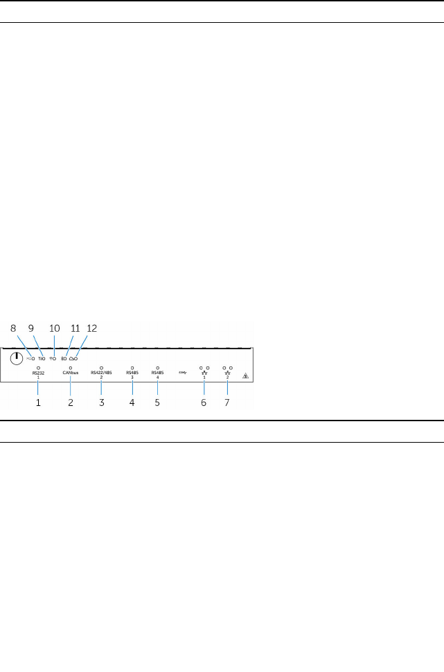
System LED Lights
Feature
1. Serial port status light Provide the status of the serial port
connection
2. CANbus port status light Provide the status of the CANbus port
connection
3. RS422/485 port status light Provide the status of the RS422/485
port connections
4. RS485 port status light Provide the status of the RS485 port
connections
5. RS485 port status light Provide the status of the RS485 port
connections
6. Network status light Indicates the connectivity status and
network activity.
7

Feature
7. Network status light Indicates the connectivity status and
network activity.
8. Power status light Indicates the power‑state of the
system.
9. Mobile broadband status light Indicates the mobile broadband status
and network activity.
10. Wireless status light Indicates the wireless connectivity
status and network activity.
11. Blutooth status light Indicates the blutooth status and
activity.
12. Cloud connection status light Indicates the could connection status.
8

Setting up your Dell Edge
Gateway
WARNING: Before you begin any of the procedures in this section,
read the safety information that shipped with your system. For
additional best practices information, go to www.dell.com/
regulatory_compliance.
WARNING: To ensure the protection provided by Dell Edge Gateway is
not impaired, do not use or install the system in any manner other
than that which is specified in this manual.
WARNING: Use cable appropriate for the load currents: 3-core cable
rated 5 A at 90 °C (194 °F) minimum, which conform to either IEC
60227 or IEC 60245. The system accept;s cables from 0.8 to 2.5 mm
(18 to 14 AWG).
WARNING: Use only the power adapter provided with DELL. The
system should be operated only with power source of the same kind as
indicated on the Power adapter rating plate. The power adapter
provided is a limited power source or SELV/limited energy circuit or
class 2 power source, rated output +19.5 VDC 65W, maximum
operating temperature 50 °C, and it is compliant to national standards
of the specific country where the system is used. Do not use different
type of power source.
Professional installation instructions
Installation personnel
This product is designed for specific applications and needs to be installed by
qualified personnel with RF and regulatory related knowledge. The general
user shall not attempt to install or change the setting.
Installation location
The product shall be installed at a location where the radiating antenna is kept
20 cm from nearby persons in its normal operation condition in order to meet
regulatory RF exposure requirements.
External antenna
Use only the antenna(s) which have been approved by the applicant. Non-
approved antenna(s) may produce unwanted spurious or excessive RF
transmitting power which may lead to a violation of FCC/IC limits and is
prohibited.
9

Installation procedure
Please refer to user’s manual for the detail.
WARNING: Please carefully select the installation position and make
sure that the final output power does not exceed the limits set forth in
relevant rules. The violation of these rules could possibly lead to
serious federal penalties.
Instructions d'installation professionnelles
Le personnel d'installation
Ce produit est conçu pour des applications spécifiques et doit être installé par
un personnel qualifié avec RF et connaissances connexes réglementaire .
L'utilisateur ne doit pas tenter générale d'installer ou de modifier le réglage.
Lieu d'installation
Le produit doit être installé à un endroit où l'antenne de rayonnement est
maintenue à 20 cm de personnes à proximité dans son état de
fonctionnement normal , afin de répondre aux exigences réglementaires
d'exposition aux radiofréquences .
Antenne externe
Utilisez uniquement l'antenne (s ) qui ont été approuvés par le demandeur .
Antenne ( s) peuvent produire de l'énergie RF parasite indésirable ou excessive
transmission qui peut conduire à une violation des normes de la FCC / IC est
interdite et non - approuvé.
Procédure d'installation
Please refer to user’s manual for the detail.
ATTENTION: S'il vous plaît choisir avec soin la position d'installation et
assurez-vous que la puissance de sortie final ne dépasse pas les limites
fixées dans les règles pertinentes . La violation de ces règles pourrait
conduire à des sanctions fédérales graves .
Federal Communication Commission
Interference Statement
This device complies with Part 15 of the FCC Rules. Operation is subject to
the following two conditions: (1) This device may not cause harmful
interference, and (2) this device must accept any interference received,
including interference that may cause undesired operation.
10

This equipment has been tested and found to comply with the limits for a
Class B digital device, pursuant to Part 15 of the FCC Rules. These limits are
designed to provide reasonable protection against harmful interference in a
residential installation. This equipment generates, uses and can radiate radio
frequency energy and, if not installed and used in accordance with the
instructions, may cause harmful interference to radio communications.
However, there is no guarantee that interference will not occur in a particular
installation. If this equipment does cause harmful interference to radio or
television reception, which can be determined by turning the equipment off
and on, the user is encouraged to try to correct the interference by one of the
following measures:
• Reorient or relocate the receiving antenna.
• Increase the separation between the equipment and receiver.
• Connect the equipment into an outlet on a circuit different from that to
which the receiver is connected.
• Consult the dealer or an experienced radio/TV technician for help.
FCC Caution:
• Any changes or modifications not expressly approved by the party
responsible for compliance could void the user's authority to operate this
equipment.
• This transmitter must not be co-located or operating in conjunction with
any other antenna or transmitter.
Radiation Exposure Statement:
This equipment complies with FCC radiation exposure limits set forth for an
uncontrolled environment. This equipment should be installed and operated
with minimum distance 20cm between the radiator & your body.
NOTE: Note: The country code selection is for non-US model only and
is not available to all US model. Per FCC regulation, all WiFi product
marketed in US must fixed to US operation channels only.
Industry Canada Statement
This device complies with Industry Canada license-exempt RSS standard(s).
Operation is subject to the following two conditions:
1 this device may not cause interference, and
2 this device must accept any interference, including interference that may
cause undesired operation of the device.
11
Le présent appareil est conforme aux CNR d'Industrie Canada applicables aux
appareils radio exempts de licence. L'exploitation est autorisée aux deux
conditions suivantes:
1 l'appareil ne doit pas produire de brouillage, et
2 l'utilisateur de l'appareil doit accepter tout brouillage radioélectrique subi,
même si le brouillage est susceptible d'en compromettre le
fonctionnement.
This Class B digital apparatus complies with Canadian ICES-003.
Cet appareil numérique de la classe B est conforme à la norme NMB-003 du
Canada.
This device complies with RSS-310 of Industry Canada. Operation is subject
to the condition that this device does not cause harmful interference.
Cet appareil est conforme à la norme RSS-310 d'Industrie Canada. L'opération
est soumise à la condition que cet appareil ne provoque aucune interférence
nuisible.
This device and its antenna(s) must not be co-located or operating in
conjunction with any other antenna or transmitter, except tested built-in
radios.
Cet appareil et son antenne ne doivent pas être situés ou fonctionner en
conjonction avec une autre antenne ou un autre émetteur, exception faites
des radios intégrées qui ont été testées.
The County Code Selection feature is disabled for products marketed in the
US/ Canada.
La fonction de sélection de l'indicatif du pays est désactivée pour les produits
commercialisés aux États-Unis et au Canada.
Radiation Exposure Statement: This equipment complies with IC radiation
exposure limits set forth for an uncontrolled environment. This equipment
should be installed and operated with minimum distance 20cm between the
radiator & your body.
Déclaration d'exposition aux radiations: Cet équipement est conforme aux
limites d'exposition aux rayonnements IC établies pour un environnement
non contrôlé. Cet équipement doit être installé et utilisé avec un minimum de
20 cm de distance entre la source de rayonnement et votre corps.
Caution:
1 The device for operation in the band 5150-5250 MHz is only for indoor
use to reduce the potential for harmful interference to co-channel
mobile satellite systems;
12
2 The maximum antenna gain permitted for devices in the bands
5250-5350 MHz and 5470-5725 MHz shall comply with the eirp limit;
and
3 The maximum antenna gain permitted for devices in the band 5725-5825
MHz shall comply with the eirp limits specified for point-to-point and
non point-to-point operation as appropriate.
4 The worst-case tilt angle(s) necessary to remain compliant with the eirp
elevation mask requirement set forth in Section 6.2.2(3) shall be clearly
indicated.
5 Users should also be advised that high-power radars are allocated as
primary users (i.e. priority users) of the bands 5250-5350 MHz and
5650-5850 MHz and that these radars could cause interference and/or
damage to LE-LAN devices.
Avertissement:
1 les dispositifs fonctionnant dans la bande 5150-5250 MHz sont réservés
uniquement pour une utilisation à l’intérieur afin de réduire les risques de
brouillage préjudiciable aux systèmes de satellites mobiles utilisant les
mêmes canaux;
2 le gain maximal d’antenne permis pour les dispositifs utilisant les bandes
5250-5350 MHz et 5470-5725 MHz doit se conformer à la limite de
p.i.r.e.;
3 le gain maximal d’antenne permis (pour les dispositifs utilisant la bande
5725-5825 MHz) doit se conformer à la limite de p.i.r.e. spécifiée pour
l’exploitation point à point et non point à point, selon le cas.
4 les pires angles d’inclinaison nécessaires pour rester conforme à
l’exigence de la p.i.r.e. applicable au masque d’élévation, et énoncée à la
section 6.2.2 3), doivent être clairement indiqués.
5 De plus, les utilisateurs devraient aussi être avisés que les utilisateurs de
radars de haute puissance sont désignés utilisateurs principaux (c.-à-d.,
qu’ils ont la priorité) pour les bandes 5250-5350 MHz et 5650-5850 MHz
et que ces radars pourraient causer du brouillage et/ou des dommages
aux dispositifs LAN-EL.
Powering on the system
1 Install the Dell Edge Gateway on the wall mount using the Dell approved
VESA mounting kit.
or
Install the Dell Edge Gateway on the rack infrastructure using the Dell
approved rail mounting kit.
13

2 Connect the network cable.
or
Install the wireless antenna to enable the wireless connections
3 Connect a display to the system.
4 Connect a keyboard and mouse if accessing the system directly.
5 Connect a SELV/limited energy circuit power source to the Dell Edge
Gateway.
6 Connect a grounding cable to the system if required.
7 Press the power button to power on the computer.
8 Is setting up the system for the first time, complete the operating system
setup.
NOTE: The Dell Edge Gateway is shipped with either Windows 10,
Ubunttu, or Wind River Linux operating systems.
9 Connect and configure to devices using the RS422/RS485 ports.
NOTE: Turn on the corresponding dip switches to enable the
corresponding RS422/R485 ports.
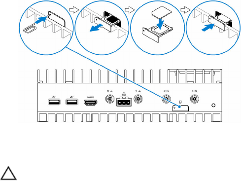
Inserting a micro-SIM card
CAUTION: It is recommended to insert the micro-SIM card before
powering on the Dell Edge Gateway.
1 Locate the micro-SIM card slot.
2 Using a paper clip or SIM eject tool eject the micro-SIM card tray.
3 Place the micro-SIM card on the tray.
CAUTION: Ensure that the micro-SIM card is aligned as shown in
the image.
14

4 Close the micro-SIM card tray.
Removing the micro-SIM card
CAUTION: Removing the micro-SIM card while it is in use may cause
data loss or result in application errors.
1 Using a paper clip or SIM eject tool eject the micro-SIM card tray.
2 Remove the micro-SIM card out of the micro-SIM card tray.
3 Replace the micro-SIM card tray into the system.
15

Setting up your operating
system
Windows 10
NOTE: For more information on setting up your Windows 10 operating
system, see www.dell.com/support/windows.
1 Power on the system.
The Windows configuration screen appears.
2 Setup the wireless connection for your system.
3 Create a local or Microsoft account.
The Windows 10 setup is complete.
Ubuntu
NOTE: For more information on setting up your Ubuntu operating
system, see www.ubuntu.com/support.
1 Power on the system.
The Ubuntu configuration screen appears.
2 Setup the wireless connection for your system.
3 Enter your login and password.
The Ubuntu operating system is setup.
Wind River Linux
NOTE: For more information on setting up your Wind River operating
system, see http://www.windriver.com/support.
1 Power on the system.
The Wind River splash screen is displayed after the Dell Edge Gateway
boots completes POST.
2 The operating system will take around twenty seconds to complete the
loading process. Enter the login information.
3 Activate your Wind River operating system installation.
The Wind River operating system is setup.
16

Specifications
System information
Product Name Industrial control equipment
Processor 6th Generation Intel Core i7
Operating system • Windows 10
• Ubuntu
• Wind river linux with Moon Island
3.0 stack
RAM LPDDR3
Storage • 32 GB SSD
• 64 GB SSD
Memory
Type LPDDR3
Speed 1600 MHz
Configurations supported 2 GB, 4 GB, and 8 GB
Ports and connectors
Audio/video One HDMI port
microSD card One microSD-card slot
Network • Two RJ45 ports
• Two wireless antenna ports
• Two mobile broadband antenna
ports
• One CANbus port
• One RS422/485 combo port
• Two RS485 port
USB • One USB 3.0 port
17

Ports and connectors
• Two USB 2.0 ports
Serial port One Serial port
Communications
Wi-Fi Dual-band 802.11b/g/n/ac
Bluetooth Bluetooth 4.1 LE
Power requirements
Phoenix connector input voltage/
current
24 VAC or 24 VDC / 4A
Power adapter input voltage/current 19.5 VDC / 3.33A
Phoenix connector Input frequency 50 Hz–60 Hz
Temperature range:
Operating 0°C to 50°C (32°F to 122°F)
Storage –40°C to 70 °C (–40°F to 158°F)
Environmental requirements
Temperature range:
Operating 0°C to 50°C (32°F to 122°F)
Non-operating -40°C to 65 °C (-40°F to 149 °F)
Relative humidity (maximum):
Operating 10% to 90% (non-condensing)
Non-operating 5% to 95% (non-condensing)
Altitude (maximum, unpressurized):
Operating -15.20 m to 3048 m (-50 ft to 10,000
ft)
Storage -15.20 m to 10,668 m (-50 ft to
35,000 ft)
18
19

Contacting Dell
To contact Dell for sales, technical assistance, or customer service issues:
1 Go to www.dell.com/contactdell.
2 Verify your country or region in the Choose a Country/Region drop-
down list at the bottom of the page.
3 Select the appropriate service or support link based on your requirement
or choose the method of contacting Dell that is convenient for you.
Dell provides several online and telephone-based support and service
options. Availability varies by country and product, and some services
may not be available in your area.
NOTE: If you do not have an active internet connection, you can
find contact information on your purchase invoice, packing slip, bill,
or Dell product catalog.
20