Murray 42583X9A User Manual LAWN MOWER 16.5 H.P. 42 Manuals And Guides L0104221
MURRAY Lawn, Tractor Manual L0104221 MURRAY Lawn, Tractor Owner's Manual, MURRAY Lawn, Tractor installation guides
User Manual: Murray 42583X9A 42583X9A MURRAY MURRAY LAWN MOWER 16.5 H.P. 42 - Manuals and Guides View the owners manual for your MURRAY MURRAY LAWN MOWER 16.5 H.P. 42 #42583X9A. Home:Lawn & Garden Parts:Murray Parts:Murray MURRAY LAWN MOWER 16.5 H.P. 42 Manual
Open the PDF directly: View PDF ![]() .
.
Page Count: 36

This Instruction Book Contains Information
For Several Models. Read And Keep This Book For
Future Reference. This Book Contains Important Information On:
SAFETY;,ASSEMBLY, OPERATION AND MAINTENANCE.
PRODUCT INFORMATION
The owner must be certain that all the product Information Is Included with this unit.
This Information Includes the INSTRUCTION BOOKS, the REPLACEMENT PARTS
and the WARRANTIES. This Information must be Included to make
sure state laws and other laws are followed.
Model
42583x9A
iiiiii
Record The Following Information About Your Unit. This Information
Is Necessary When Ordering Parts Or In Case Of Loss Or Theft,
WHERE PURCHASED:
DATE PURCHASED: Month Day Year
MODEL NO.: DATE OF MANUFACTURE:
BUILT IN THE
I.-IfA
F- 98889
TABLE OF CONTENTS
WARRANTY ......................................... 2
RESPONSIBILITY OF THE OWNER .................... 3
SAFETY RULES ..................................... 3
ASSEMBLY .......................................... 9
PARTS BAG ÷ CONTENTS ................................ 9
CHECK THE TIRES ...................................... 9
CHECK THE LEVEL OF THE MOWER HOUSING ............ 9
HOW TO INSTALL THE SEAT .............................. 10
HOW TO ASSEMBLE THE STEERING WHEEL .............. 10
HOW TO ASSEMBLE THE GAUGE WHEELS ................ 10
MAINTENANCE FREE BATTERY .......................... 11
HOW TO PREPARE THE ENGINE .......................... 11
IMPORTANT! BEFORE YOU START MOWING .............. 11
OPERATION ......................................... 12
LOCATION OF CONTROLS ............................... 12
A'I-rACH MENTS .......................................... 13
HOW TO USE THE THROTTLE CONTROL .................. 13
HOW TO USE THE BLADE ROTATION CONTROL ........... 13
HOW TO USE THE SPEED CONTROL PEDAL ............... 14
HOW TO DISCONNECT THE TRANSMISSION ............... 14
HOW TO SET THE PARKING BRAKE ....................... 15
HOW TO CHARGE THE CUTTING HEIGHT .................. 18
HOW TO STOP THE UNIT ................................. 15
HOW TO TRANSPORT THE UNIT .......................... 15
HOW TO OPERATE WITH THE MOWER HOUSING ........... 16
HOW TO OPERATE THE UNIT ON HILLS ................... 16
BEFORE STARTING THE ENGINE ......................... 17
HOW TO START THE ENGINE ............................. 17
OPERATING TIPS ........................................ 18
MOWING AND BAGGING TIPS ............................ 18
HOW TO CHANGE THE MDLCHER PLATE .................. 19
MAINTENANCE ...................................... 20
MAINTENANCE CHART .................................. 20
HOW TO CHECK THE MUFFLER .......................... 20
HOW TO REMOVE AND INSTALL THE BLADE .............. 21
HOW TO SHARPEN THE BLADE .......................... 21
HOW TO ADJUST THE BLADE ROTATION CONTROL ........ 22
HOW TO CHECK AND ADJUST THE DRIVE BRAKE ......... 23
HOW TO CHECK AND ADJUST THE MOTION DRIVE BELT . . .23
HOW TO ADJUST THE SPEED CONTROL PEDAL ........... 24
MAINTENANCE FREE BAI-flERY .......................... _1
HOW TO CHARGE THE BATTERY ......................... 24
WHERE TO LUBRICATE .................................. 25
HOW TO CHECK THE FUEL FILTER ....................... 25
CHECK THE TIRES ...................................... 25
HOW TO REMOVE THE MOWER HOUSING ................. 26
HOW TO INSTALL THE MOWER HOUSING ................. 26
HOW TO LEVEL THE MOWER HOUSING ................... 27
HOW TO REPLACE THE MOTION DRIVE BELT .............. 28
HOW TO REPLACE THE MOWER DRIVE BELT .............. 29
HOW TO REPLACE THE FUSE ............................ 30
HOW TO REPLACE THE LIGHT BULB ...................... 30
HOW TO CLEAR THE MOWER HOUSING ................... 30
STORAGE (OVER 30 DAYS) ............................... 30
TROUBLE SHOOTING CHART ........................ 31
SLOPE GUIDE ....................................... 32
INDEX .............................................. 35
LAWN TRACTOR ACCESSORIES ...................... 36
MURRAY, INC. Two Year Limited Warranty
Murray, Inc. warrants to the original purchaser that this unitshall be flee from defects in material and workmanship under normal
use and service for a period of Two (2) Years from the date of purchase; however, this warranty does not cover engines,
accessories (such as snow blowers, snow blades, grass baggers and plows), transmissions, batteries and Normal Wear Parts
(except as noted below) ortransaxles as the companies that manufacture these items furnish their own warranties and provide
service through their authorized field service facilities. For additional information, see the warranties covering these particular
parts, If you are uncertain whether your unit contains or is equipped with one or more of these parts, consult your dealer prior
to purchase. Subject to the terms and conditions noted inthis Limited Warranty, we shall, at our option, repair or replace at no
cost to the original purchaser any part covered by this Limited Warranty during the applicable warranty period.
In the event the battery proves defective within ninety (90) days from the date of purchase, we willreplace it without charge, If
the battery proves defective after (90) days but within one hundred twenty (120) days from the date of purchase, we willreplace
itfor a charge of one half (1/2) of the retail price of the battery in effect at the time of return.
Normal Wear Parts are defined as belts, blades, blade adapters, pneumatic tires, headlights and seat covers, These parts are
warranted to be free from defects in material and workmanship as delivered with the product. Any claim for repair or replacement
of Normal Wear Parts must be made within thirty (30) days of the date of purchase. No claims invoMng damage caused from
material use, abuse or misuse will be honored.
This Murray, Inc. Two (2) Year Limited Warranty is your exclusive remedy; however, this warranty is void or does not app|y
to any unit that has been tampered with, altered, misused, abused or used for rental or other commercial and/or professional
(non- homeowner) uses. Yourwarranty does not cover minor mechanical adjustments which are not due to any defect in material
or workmanship, For assistance in making such adjustments, consult your Instruction Book.
To make a claim under this Murray, Inc. Two (2) Year Limited Warranty, return the unit (or if authorized in advance, the defective
part) along with your proof of purchase to an Authorized Service Center near you. To locate the nearest Authorized Service
Center, call the Central Pads Distributor for your area shown in the list provided with your unit or check the Yellow Page listings
in your local telephone directory. If you return the entire unit, we will repair the unit. Ifwe authorize the return of the defective
part only, we will either replace or repair the part. In the case of a defect in a transmission or differential (as distinguished from
atransaxle), the entire transmission or differential must be returned since they do not include user serviceable parts.
This Murray, Inc. Two (2) Year Limited Warranty gives you specific legal rights, and you may also have other rights which vary
from state to state. This Limited Warranty is given in lieu of all other expressed and implied warranties including the
implied warranty of merchantability and warranty of fitness for a particular purpose. If you need additional information
on this written warranty or assistance in obtaining service, write or call: MURRAY, INC., Outdoor Power Equipment, Customer
Service Department, P.O. Box 268, Brentwood, Tennessee 37027. (t- 800- 251- 8007)
F-98889 2
OWNER'S INFORMATION
This instructionbookisforseveraldifferentmodels.Theinstructions
are writtenfor a personwithsomemechanicalability.Likemostser-
vicebooks,notallthestepsare described.Stepsonhowtoloosenor
tightenfastenersarestepsanyonecanfollowwith somemechanical
ability.Readandfollowtheseinstructionsbeforeyouusethe unit.
Knowyourproduct:lfyou understandthe unitand howthe unitoper-
afas,youwillget the best performance.As you readthis manual, com-
pare the illustrationsto the unit.Learn the location and the functionof
the controls•To help prevent an accident, followthe operating instruc-
tions andthe safety rules, Keep this manual for future reference.
IMPORTANT: Many unitsare not assembledand are sold incar-
tons.It istheresponsibilityofthe ownerto makesurethe assembly
instructionsinthismanualare exactlyfollowed. Otherunitsarepur-
chased inan assembled condition. On assembled units, it is the re-
sponsibility of the owner to make sure the unit is correctly
assembled. The owner must carefully check the unit according to
the instructions in this manual before it is first used.
RESPONSIBILITY OF THE OWNER
11rerns_nsibility of the owneris to follow the instructions below.
1. Carefullyreadand follow the rulesfor safe operation•
2. Followallthe assemblyinstructions.
3. Inspectthe unit.
4. Make surethatthe operatorof the unitknowshowto correctly
use allstandardand accessoryequipment.
5. Operate the unitonly withguards, shields,and othersafety
items inplaceand workingcorrectly.
6. Correctlyadjustthe unit.
7. Servicethe unitonlywithauthorizedorapprovedreplacement
parts.
8. Completeallmaintenanceon the unit.
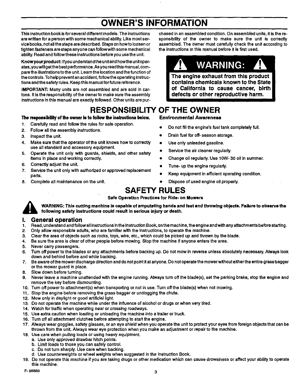
Environmental Awareness
• Do not fill the engine's fuel tank completely full.
• Drain fuel for off- season storage.
• Use only unleaded gasoline.
•Service the air cleaner regularly.
•Change oil regularly, Use 10W- 30 oil in summer.
•Tune- up the engine regulady.
•Keep equipment in efficient operating condition.
•Dispose of used engine oil properly.
A
SAFETY RULES
Safe Operation Practices for Ride- on Mowers
WARNING: This cutting machine is capable of amputating hands and feet and throwing objects. Failure to observe the
following safety instructions could result in serious injury or death.
I. General operation
1. Read, understand and follow allinstructions inthe InstructionBook, onthe machine, the engine and withany attachments before starting.
2. Only allow responsible adults, who are familiar with the instructions,to operate the machine.
3. Clear the area of objects such as rocks, toys, wire, etc., which could be picked up and thrown by the blade.
4. Be sure the area is clear of other people before mowing. Stop the machine if anyone enters the area.
5. Never carry passengers.
6. Turn off power to the blades or any attachments before backing up. Do not mow in reverse unless absolutely necessary. Always look
clown and behind before and while backing.
7. Be aware ofthe mower discharge direction and do notpoint itat anyone. Do not operate the mower without either the entiregrass bagger
or the mower guard in place.
8. Slow down before turning.
9. Never leave a machine unattended with the engine running. Always turn off the blade(s), set the parking brake, stop the engine and
remove the key before dismounting.
10. Turn off power to attachment(s) when transporting or not in use. Turn offthe blade(s) when not mowing.
11. Stop the engine before removing the grass bagger or unclogging the chute.
12. Mow only in daylight or good artificial light.
13. Do not operate the machine while under the influence of alcohol or drugs or when very tired.
14. Watch for traffic when operating near or crossing roadways.
15. Use extra caution when loading or unloading the machine into a trailer or truck.
16. Turn off all attachment clutches before attempting to start the engine.
17. Always wear goggles, safety glasses, or an eye shield when you operate the unitto protect your eyes from foreign objects that can be
thrown from the unit.Always wear eye protection when you make an adjustment or repair to the machine.
18. Use care when pulling loads or using heavy equipment.
a. Use only approved drawbar hitoh points.
b. Limit loads to those you can safely control.
c. Do not turn sharply. Use care when backing.
d. Use counterweights or wheel weights when suggested in the Instruction Book.
t9. Do not operate this machine if you are taking drugs or other medication which can cause drowsiness or affect your ability to operate
this machine.
F- 98889
OWNER'S INFORMATION
20. Do not use this machine ifyou are mentally or physically unable to operate this machine safely.
II. Slope operation
Slopes and rough terrain are major factors related to loss- of- control and tip- over accidents, which can result in severe injury
or death. ALL slopes require extra caution. If you cannot back up the slope or if you feel uneasy on the slope, do not mow it. See
the =Slope Guide" in the back of this book to check for safe operation.
DO
1. Mow up and down slopes, not across.
2. Remove obstacles such as rocks, limbs, etc.,.
3. Watch for holes, ruts or bumps. Uneven terrain could overturn the machine. Tall grass can hide obstacles.
4. Use slow speed on slopes. Do not make sudden speed changes.
5. Follow the manufacturer's recommendations for wheel weights or counterweights to improve stability.
6. Use extra care with grass baggers or other attachments, they can change the stability ofthe machine.
7. Keep all movement on the slopes slow and gradual. Do not make sudden changes in speed or direction.
8. Avoid starting or stopping on aslope. Iftires lose traction, turn off the blades and proceed slowly straight down the slope.
DO NOT
1. Do not turn on slopes unless absolutely necessary, then only turn slowly and gradually downhill, ifpossible.
2. Do not mow drop. offs, ditches or embankments. A wheel over the edge or an edge caving in could cause a sudden overturn and an
injury or death.
3. Do not mow on wet grass. Reduced traction could cause sliding.
4. Do not try to stabilize the machine by putting your foot on the ground.
5. Do not use a grass bagger or other rear mounted accessories on steep slopes (greater than 10 degrees).
II1. Children
Tragic accidents can occur it the operator is not alert to the presence of children. Children are often attracted to the machine and
the mowing activity. NEVER assume that children will remain where you last saw them.
t. Keep children out of the mowing area and in the watchful care of another responsible adult.
2. Be alert and turn the engine off ifchildren enter the area.
3. Before and when backing, look behind and down for small children.
4. Never carry children or any passengers, even with the blades off. They may fall off and be seriously injured or interfere with the safe
operation of the machine.
5. Never allow children to operate the machine. Instruct children in the potential dangers of the machine.
6, Use extra care when approaching blind corners, shrubs, trees or other objects that may obscure vision.
IV. Service
1, Use extra care when handling gasoline and other fuels. Fuels are flammable and the vapors are explosive.
a. Use only an approved container.
b. Never remove the gas cap or add fuel with the engine running. Allow the engine to cool for several minutes before refueling. Do
not smoke.
c. Never refuel the machine indoors.
d. Never store the machine with fuel in the tank or fuel container inside where there is an open flame, such as a water heater.
2. Never start or runthe engine inside a closed area.
3. Keep all nuts and bolts, especiany the blade attachment nuts tight. Frequently check the blade(s) for wear or damage such as cracks
and nicks. A blade that is bent or damaged must be immediately replaced with an original equipment blade from an authorized service
dealer. For safety, replace the blade every two years. Keep the equipment in good condition.
4, Never tamper with the safety devices. Check their proper operation regularly.
5, To reduce fire hazards, keep the machine free of grass, leaves or other debris build- up. Clean up oil or fuel spills.Allow the machine
to cool before storing.
6. Stop and inspect the equipment if you strike an object. Repair, ifnecessary, before restarting.
7. Never make adjustments or repairs with the engine running. The carburetor can be adjusted with the engine running. Do not change
the engine governor settings or over- speed the engine.
8. Grass bagger components are subject to wear, damage and deterioration, which could expose moving parts or allow objects to be
thrown. For storage, always make sure the grass bag is empty. Frequently check components and replace with manufacturer's recom-
mended parts when necessary.
9. Mower blade(s)are sharp and can cut.Wrapthe blade(s)or wear gloves and use extra caution when servicing them ortha blade housing
area.
10. Check the brake operation frequently. Adjust and service as required.
11. Wait for all movement to stop before servicing any part of the unit.
,_ Look for this symbol to indicate important safety
precautions. This symbol indicates: "Attention!
Become Alert! Your Safety Is At Risk."
F- 98889 4
Eachpersonthatoperatespower
equipmentmustlearntousecorrectand
safemowingprocedures.Tohelpyou
learn,carefully read the following
pages. Most of the time the operator was
not correctly shown or did not read the
instructions on the unit or in the Instruction
Book before using the unit. Also, some
operators do not have enough experience.
The result is unsafe use, endangering the
operator, bystanders and the equipment.
Another result can be a poor appearance
of the area mowed.
Read this book, Read the instructions on
the unit. Operate the mower according to
the Safe Mowing Guide. Follow all safety
rules, cautions or warnings in this book
and on the unit. Make sure anyone that
uses the unit reads the instructions and is
told how to safely operate the mower.
The mower will give you good service and
durability, if operated in normal conditions.
Ifthe mower is not correctly serviced or is
used where the terrain is rough or
unsuitable, product performance and
safety wi}lbe decreased.
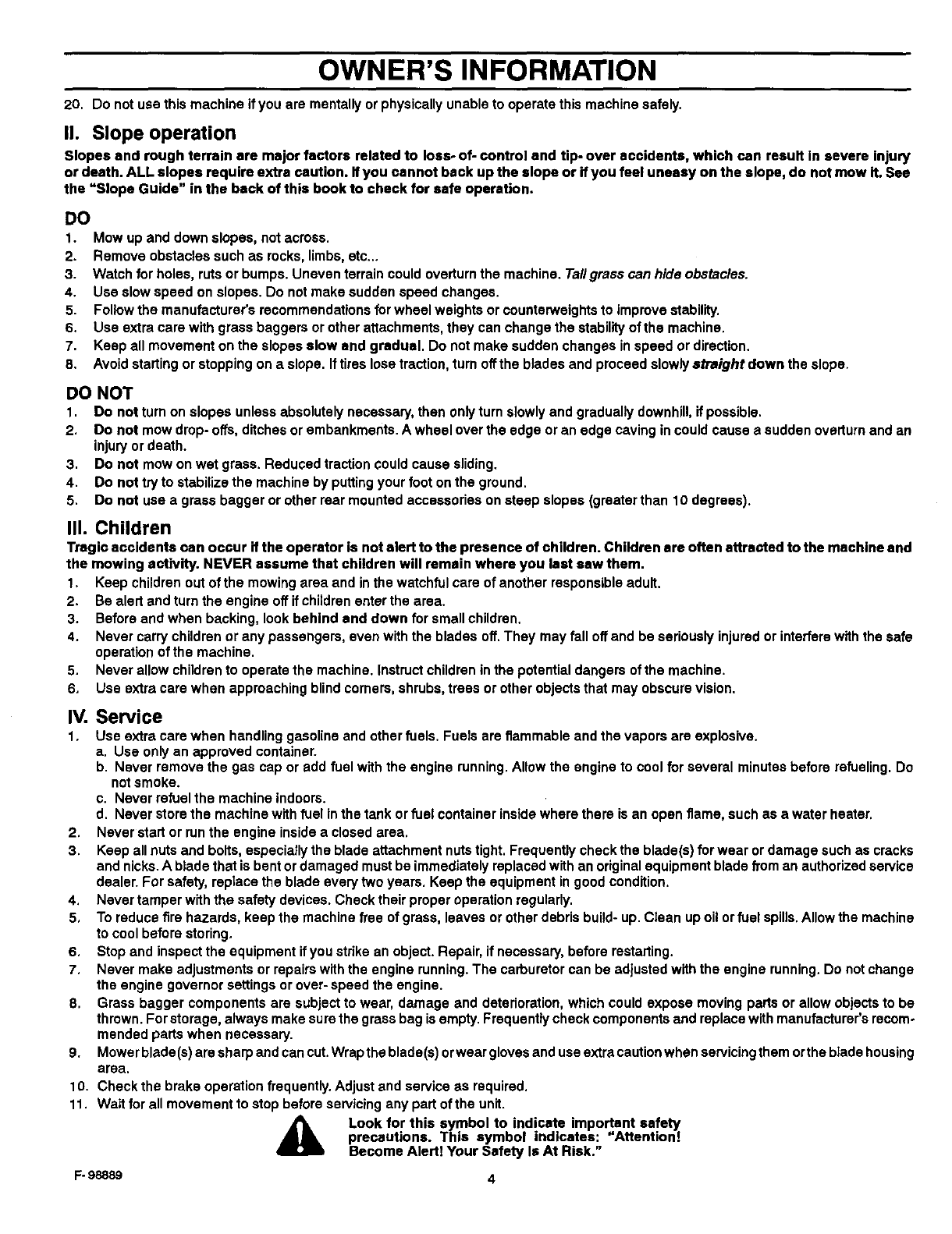
Correct clothing is an important part of safe
mowing. Safety glasses will protect the
eyes from objects discharged by the
mower. Safety shoes with steel plates can
protect a foot from injury by the blade. For
protection from objects discharged from
the mower, wear clothing that will cover the
arms and legs.
Before you stad cutting the grass, practice
using the mower in a large open and level
area. Learn the location of the controls on
the mower. Know the purpose of the
F- 98889
SAFE MOWING GUIDE
controls and how they work. In an
emergency, how fast you can stop the
blade is important. Learn how to control
the mower at all times.
Many enginesare startedby hand.When
you use apullstartor ropestart,place
your feet apartand awayh'omthe blade(s).
Holdthe rope handletight.Neverwrapthe
rope aroundyour armorfingersfor a
=bettergrip'.Tostartthe engine,followthe
instructionsonthe mower,inthisbookand
inthe engineoperatinginstructions.
For electric start engines, sit inthe seat to
start the engine. The battery can be
dangerous. Follow the instructions on the
battery, the acid container, and in this book
when working with the battery, Even small
batteries have enough voltage to cause an
injury.Always be careful.
The mower is designed to be operated by
one person. Never let another person dde
with you on the unit or on any accessories.
A passenger will make the unit harder to
control, block the visibility or distract the
operator and is dangerous to the operator,
the passenger and the equipment. Without
apassenger seat, the passenger can fall
from the mower or contact dangerous
parts. A mower is not a toy for showing off
or for giving rides.
Never cut a wet lawn. Wet grass can
cause an accident, affect mower
performance and can cause problems with
future lawn growth and appearance. Wet
grass is slippery and can cause the mower
to slip. Someone can get injured by
touching the blade(s). Wet grass tends to
clog the mower, causing poor discharge.
Cut wet grass will collect on the lawn,
retarding the growth of the grass. Also,
getting the mower wet will cause parts to
rust and decrease the life of the unit.
When you look over the lawn, remember
obstacles that cannot be removed, like
pipes, stumps or rocks. Keep away from
these obstacles that can cause damage to
the mower or injury to the operator or a
person near the mower. Clear the area of
rocks, toys, wire or other loose objects.
These items can damage the mower or
can be discharged by the mower blade.
The blade of a power mower rotates very
fast. It can discharge rocks and other
objects over a long distance which can be
dangerous. The force of the objects can
break windows, cause injuries or even put
an eye out. Most of the time the injury is to
a person, like a child. Keep every person
completely away from the area to be
mowed. Make sure the grass is not
discharged toward anyone. Planning your
mowing pattern has a double advantage. It
can decrease the possibility of an injury
and make the clean up after mowing
easier.
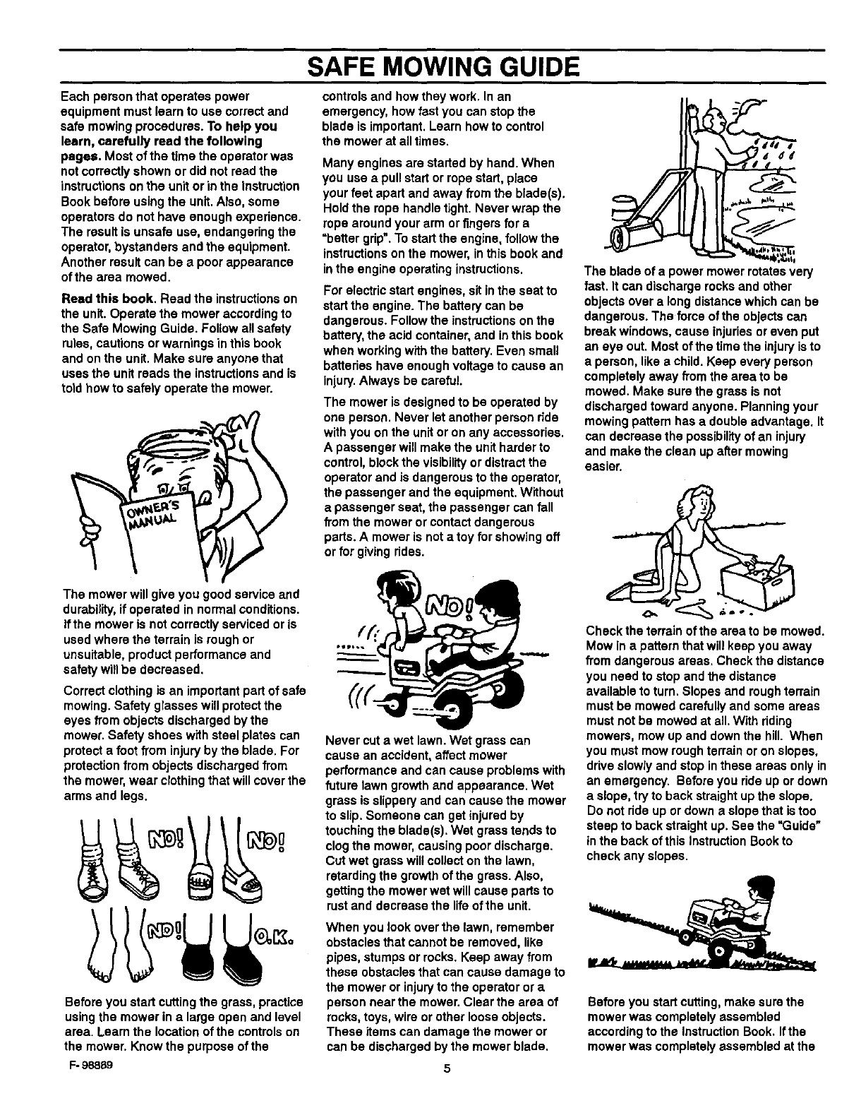
Check the terrain of the area to be mowed.
Mow in a pattern that will keep you away
from dangerous areas. Check the distance
you need to stop and the distance
available to turn. Slopes and rough terrain
must be mowed carefully and some areas
must not be mowed at all. With riding
mowers, mow up and down the hill. When
you must mow rough terrain or on slopes,
drive slowiy and stop inthese areas only in
an emergency. Before you ride up or down
a slope, try to back straight up the slope.
Do not ride up or down a slope that istoo
steep to back straight up. See the "Guide"
Inthe back of this Instruction Book to
check any slopes.
Before you start cutting, make sure the
mower was completely assembled
according to the Instruction Book. Ifthe
mower was completely assembled at the
store,youmuststillcheckthemower
accordingtotheassemblyinstructions.
Makesurethemoweriscorrectly
assembledandthatallfastenersaretight.
Makesuretheenginehasthecorrect
amountofoil.Checktheseitemsoften
duringthelifeofthemower.
Yourmowerhasagasolineengine.
Gasolineisadangerousfuel.Keep
gasolineonlyinanapprovedsafety
gasolinecontainer.Donotkeeplarge
amounts of gasoline. When you add
gasoline to the fuel tank, do not smoke.
Store the gasoline container and the
mower in an area that has good ventilation.
Also, keep the gasoline away from any
flames like the pilot lightof a furnace or
any other source of ignition, if the mower is
to be stored for more than a few weeks,
remove the gasoline from the fuel tank.
When inside an enclosure, do not add
gasoline to the fuel tank. Before you add
gasoline, move the mower outside and add
gasoline carefully. Before you start the
engine, remove any gasoline from the
outside of the fuel tank or from the mower.
Warm gasoline will expand. Leave some
space in the fuel tank for the gasoline to
expand. Also, the fuel cap has a vent hole
for fuel vapors. Always use the correct fuel
cap. Failure to follow safety rules about
gasoline will cause fires and explosions,
injuryto you and damage to the equipment
and other property.
If you add gasoline to an engine that is
running or hot, the result can be an
explosion. Before you add gasoline, stop
the engine and let the engine cool for
several minutes. Remove dry grass and
other debris from the mower. Keep the
mower clean to improve the performance,
help the engine and transmission run
cooler, extend the life of moving parts, and
decrease the danger of a fire.
Fires and explosions are not the only
dangers when working around a mower.
The engine, transmission, and the muffler
will get hot in several minutes when the
engine is running. Do not touch these parts
of the mower. Stop the engine. Let the
F- 98889
SAFE MOWING GUIDE
engine and transmission cool before
servicing the mower. Remember, exhaust
fumes are dangerous. Never operate the
engine inside a building.
When you get a new mower, it can be a
new experience for the family. Tell each
person how a mower can be dangerous.
Remember, a mower is not a toy. A mower
is not to be used by children or anyone not
old enough, strong enough or that does not
have experience.
Ifthe mower is not correctly assembled,
not operated correctly, or not regularly
serviced, the mower can be dangerous.
The most important rule to follow is always
use good judgement and common sense.
Mow safely and carefully.
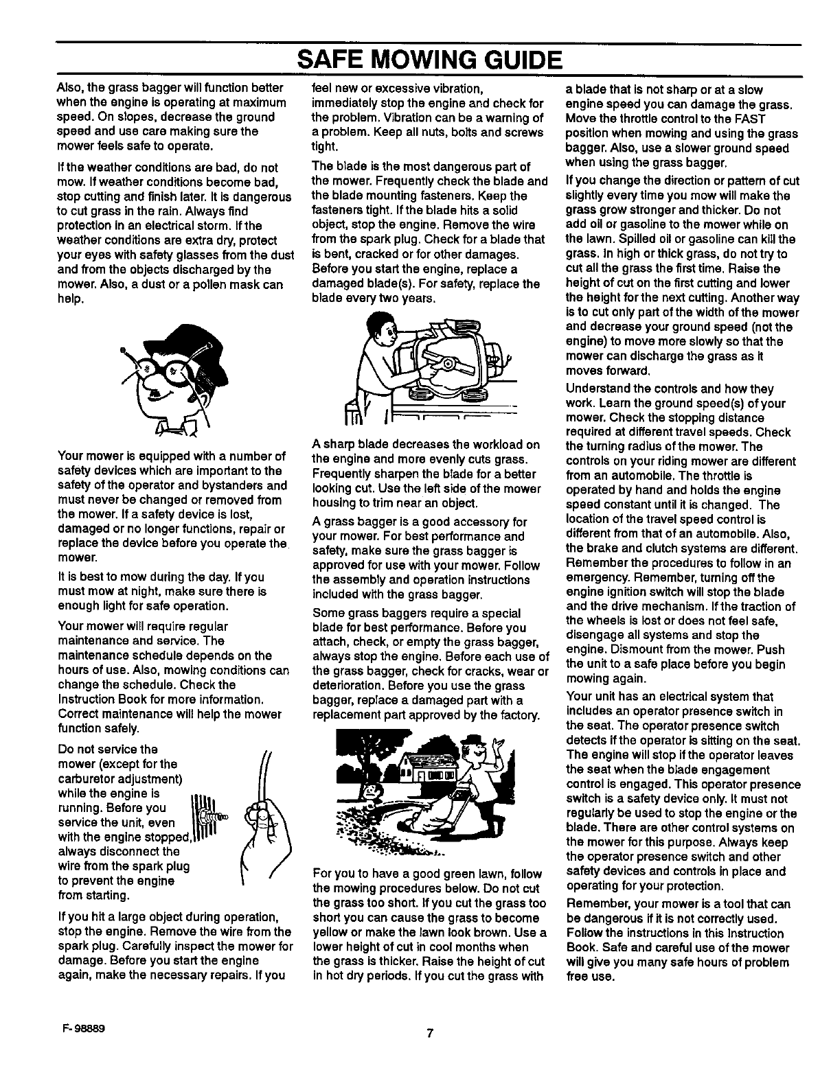
Your mower will easily cut thick grass.
Fingers, feet and other parts can also be
cut by the blade. Injuries occur when the
operator does not think and reaches into
the chute opening. Always operate the
mower as ifthe blade is rotating. Do not
service or make an adjustment, except to
the carburetor, while the engine is running.
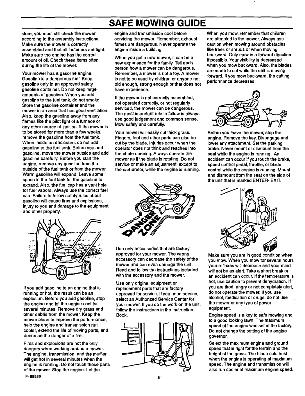
When you mow, remember that children
are attracted to the mower. Always use
caution when mowing around obstacles
like trees or shrubs or when moving
backward. Only mow in a forward direction
if possible. Your visibility is decreased
when you mow backward. Also, the blades
are made to cut while the unit is moving
forward. If you mow backward, the cutting
performance decreases.
Before you leave the mower, stop the
engine. Remove the key. Disengage and
lower any attachment. Set the parking
brake. Never mount or dismount from the
seat while the engine is running. An
accident can occur if you touch the brake,
speed control pedal, throttle, or blade
controlwhile the engine is running. Mount
and dismount from the seat on the side of
the unit that is marked ENTER- EXIT.
Use only accessories that are factory
approved for your mower. The wrong
accessory can decrease the safety of the
mower and can even damage the unit.
Read and follow the instructions included
with the accessory and the mower.
Use only original equipment or
replacement parts that are factory
approved for service. Ifyou need service,
select an Authorized Service Center for
your mower. If you do the work on the unit,
follow the instructions inthe Instruction
Book.
Make sure you are in good condition when
you mow. When you mow for several hours
your reflexes will decrease and your mind
will not be as aTert.Take a short break or
an accident can occur, if the temperature is
hot, use caution to prevent dehydration. If
you are tired, angry or not completely alert,
do not operate the mower. If you use
alcohol, medication or drugs, do not use
the mower or any type of power
equipment.
Engine speed is a key to safe mowing and
to a good looking lawn. The maximum
speed of the engine was set at the factory.
Do not change the setting of the engine
governor.
Select the maximum engine and ground
speed that is right for the terrain and the
height of the grass. The blade cuts best
when the engine is operating at maximum
speed. The engine and transmission will
also run cooler at maximum engine speed.
6
SAFE MOWING GUIDE
Also, the grass bagger will function better
when the engine is operating at maximum
speed. On slopes, decrease the ground
speed and use care making sure the
mower feels safe to operate.
Ifthe weather conditions are bad, do not
mow. If weather conditions become bad,
stop cutting and finish later. It is dangerous
to cut grass in the rain. Always find
protection in an electrical storm. If the
weather conditions am extra dry, protect
your eyes with safety glasses from the dust
and from the objects discharged by the
mower. Also, a dust or apollen mask can
help.
Your mower is equipped with a number of
safety devices which are important to the
safety of the operator and bystanders and
must never be changed or removed from
the mower. If asafety device is lost,
damaged or no longer functions, repair or
replace the device before you operate the
mower.
It is best to mow during the day. Ifyou
must mow at night, make sure there is
enough light for safe operation.
Your mower will require regular
maintenance and service. The
maintenance schedule depends on the
hours of use. Also, mowing conditions can
change the schedule. Check the
Instruction Book for more information.
Correct maintenance will help the mower
function safely.
Do not service the
mower (except for the
carburetor adjustment)
while the engine is
running. Before you I_ l
service the unit, even _l_l_'l'_
with the engine stopped,tiP'"
always disconnect the
wire from the spark plug
to prevent the engine
from starting.
If you hit a large object during operation,
stop the engine. Remove the wire from the
spark plug. Carefully inspect the mower for
damage. Before you start the engine
again, make the necessary repairs. Ifyou
feel new or excessive vibration,
immediately stop the engine and check for
the problem. Vibration can be a warning of
a problem. Keep all nuts, bolts and screws
tight.
The blade is the most dangerous part of
the mower. Frequently check the blade and
the blade mounting fasteners. Keep the
fasteners tight. If the blade hits a solid
object, stop the engine. Remove the wire
from the spark plug. Check for a blade that
is bent, cracked or for other damages.
Before you start the engine, replace a
damaged blade(s). For safety, replace the
blade every two years.
A sharp blade decreases the workload on
the engine and more evenly cuts grass.
Frequently sharpen the blade for a better
looking cut. Use the left side of the mower
housing to trim near an object.
A grass bagger is a good accessory for
your mower. For best performance and
safety, make sure the grass bagger is
approved for use with your mower. Follow
the assembly and operation instructions
included with the grass bagger.
Some grass baggers require a special
blade for best performance. Before you
attach, check, or empty the grass bagger,
always stop the engine. Before each use of
the grass bagger, check for cracks, wear or
deterioration. Before you use the grass
bagger, replace a damaged part with a
replacement part approved by the factory.
For you to have a good green lawn, follow
the mowing procedures below. Do not cut
the grass too short. If you cut the grass too
short you can cause the grass to become
yellow or make the lawn look brown. Use a
lower height of cut in cool months when
the grass isthicker. Raise the height of cut
in hot dry periods. Ifyou cut the grass with
a blade that is not sharp or at aslow
engine speed you can damage the grass.
Move the throttle control to the FAST
position when mowing and using the grass
bagger. Also, use a slower ground speed
when using the grass bagger.
Ifyou change the direction or pattern of cut
slightly every time you mow will make the
grass grow stronger and thicker. Do not
add oil or gasoline to the mower while on
the lawn. Spilled oil or gasoline can killthe
grass. In high or thick grass, do not try to
cut all the grass the firsttime. Raise the
height of cut on the first cutting and lower
the height for the next cutting.Another way
is to cut only part of the width of the mower
and decrease your ground speed (notthe
engine) to move more slowly so that the
mower can discharge the grass as it
moves forward.
Understand the controls and how they
work. Learn the ground speed(s) of your
mower. Check the stopping distance
required at different travel speeds. Check
the turning radius of the mower. The
controls on your riding mower are different
from an automobile. The throttle is
operated by hand and holds the engine
speed constant until it is changed. The
location of the travel speed control is
different from that of an automobile. Also,
the brake and clutch systems are different.
Remember the procedures to follow in an
emergency. Remember, turning off the
engine ignitionswitch will stop the blade
and the drive mechanism. If the traction of
the wheals is lost or does not feel safe,
disengage all systems and stop the
engine. Dismount from the mower. Push
the unit to a safe place before you begin
mowing again.
Your unit has an electrical system that
includes an operator presence switch in
the seat. The operator presence switch
detects ifthe operator is sittingon the seat.
The engine will stop ifthe operator leaves
the seat when the blade engagement
control is engaged. This operator presence
switch is a safety device only. It must not
regularly be used to stop the engine or the
blade. There are other control systems on
the mower for this purpose. Always keep
the operator presence switch and other
safety devices and controls in place and
operating for your protection.
Remember, your mower is a tool that can
be dangerous if it is not correctly used.
Follow the instructions inthis Instruction
Book. Safe and careful use of the mower
will give you many safe hours of problem
free use.
F- 98889 7
STEPS TO FOLLOW
BEFORE MOWING
• Be sure to dress correctly.Wear hard shoes, not sandals or tennis shoes.
•Examine the blade. A blade that is bent, cracked, or damaged must be replaced with a factory replacement blade.
•Fill the fuel tank outside. Clean off spUled fuel.
•Read and follow the Owner's Manual, the instructions with the engine, and the instructions with any attachments. Owner's Manual
instructions are for your safety and the safety of others.
•Exhaust fumes are dangerous. Start the engine outside.
• Make sure all safety devices are in place and working correctly.
•Operation of the mower is only for a person that has experience.
•Wet grass can be dangerous. Let the grass dry.
•Instruct children and others to keep away from the work area.
•Never cut the grass without good light.
•Pick up loose objects. Remove them from the mowing area.
WHILE MOWING
•Watch for fixed objects and avoid them. They can damage the mower or cause injury.
•A hot engine, muffler, and transmission will cause a burn. Do not touch.
•_nc__nesands__pesmustbecarefui_ym_wed_Se_the_Guide_intheback_fthisb__kt_checkas__pe_
•Lack of daylight or good artificial light is cause to stop mowing.
•Examine the mower, the blade, and other parts for damage after hitting aforeign object or ifthe unit vibrates excessively.
•Do not make adjustments or repairs without stopping the engine. Disconnect the spark plug wira.
•On or near roads, watch out for traffic. Direct discharge away from roads.
•When mowing, avoid areas where traction is unsure. Look back before changing direction of travel.
•In heavy grass, raise the cutting height. Cut slower. Stop the engine to remove clogged grass from the mower.
•Never remove any safety related parts.
•Do not pour gasoline into a engine that is hot or running.
AFTER MOWING
•Always let the mower cool before storing in an enclosed area.
•Foreign material on the mower is dangerous. Clean off grass, leaves, grease and oil before storing.
•Tighten all loose nuts, bolts and screws before you use the unit.
•Empty and clean any grass catcher or other accessory.
•Remove the key or disconnect the spark plug wire to prevent unauthorized use.
•Make sure the mower is not kept near a source of ignition. Gas fumes can cause an explosion.
•Only original parts or factory approved substitutes can be used to service the mower.
•When storing the mower for an extended period, remove the fuel from the fuel tank.
•Instruct children to leave the mower alone. It is not a toy.
•Never keep gasoline near a source of ignition. Always use an approved container. Keep gasoline away from children.
•Lubricate according to the Instruction Book. See =Lubrication'.
IMPORTANT-- Read the Instruction Book. Keep this book for future use and reference.
,_ WARNING: Look for this symbol to point out important
safety precautions. It means: "Attention! Become Alert!
Your Safety Is Involved."
F- 98889 8
ASSEMBLY
ASSEMBLY
This instruction book is for several models. Some parts oraccesso-
ries are not included on all models. Read and follow the assembly
and adjustment instructions for your mower. All fasteners are inthe
parts bag, Do not discard any parts or material until the unit is
assembled.
A WARNING: Before doing any assembly or mainte-
nance to the mower, remove the wire from the spark
plug.
NOTE: In this instruction book, left and right describe the loca-
tion of a part with the operator on the seat.
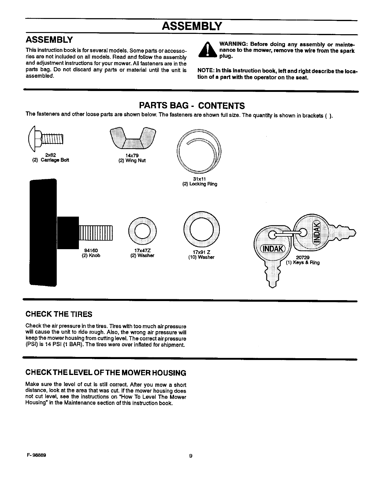
PARTS BAG - CONTENTS
The fasteners and other loose parts are shown below. The fasteners are shown full size. The quantity is shown in brackets ().
2x82
(2) CarriageBolt
9416O
(2) Knob
14x79
(2)Wing Nut
17x47Z
(2)Washer
31xll
(2)LockingRing
17x91Z
(lO)Washer
(1) Keys & Ring
CHECK THE TIRES
Check the air pressure in the tires. Tires with too much air pressure
will cause the unit to ride rough. Also, the wrong air pressure will
keep the mower housing from cutting level. The correct air pressure
(PSI) is 14 PSI (t BAR). The tires were over inflated for shipment.
CHECK THE LEVEL OFTHE MOWER HOUSING
Make sure the level of cut is still correct. After you mow a short
distance, look at the area that was cut. If the mower housing does
not cut level, see the instructions on =How To Level The Mower
Housing" in the Maintenance section of this instruction book.
F- 98889 9
ASSEMBLY
3.
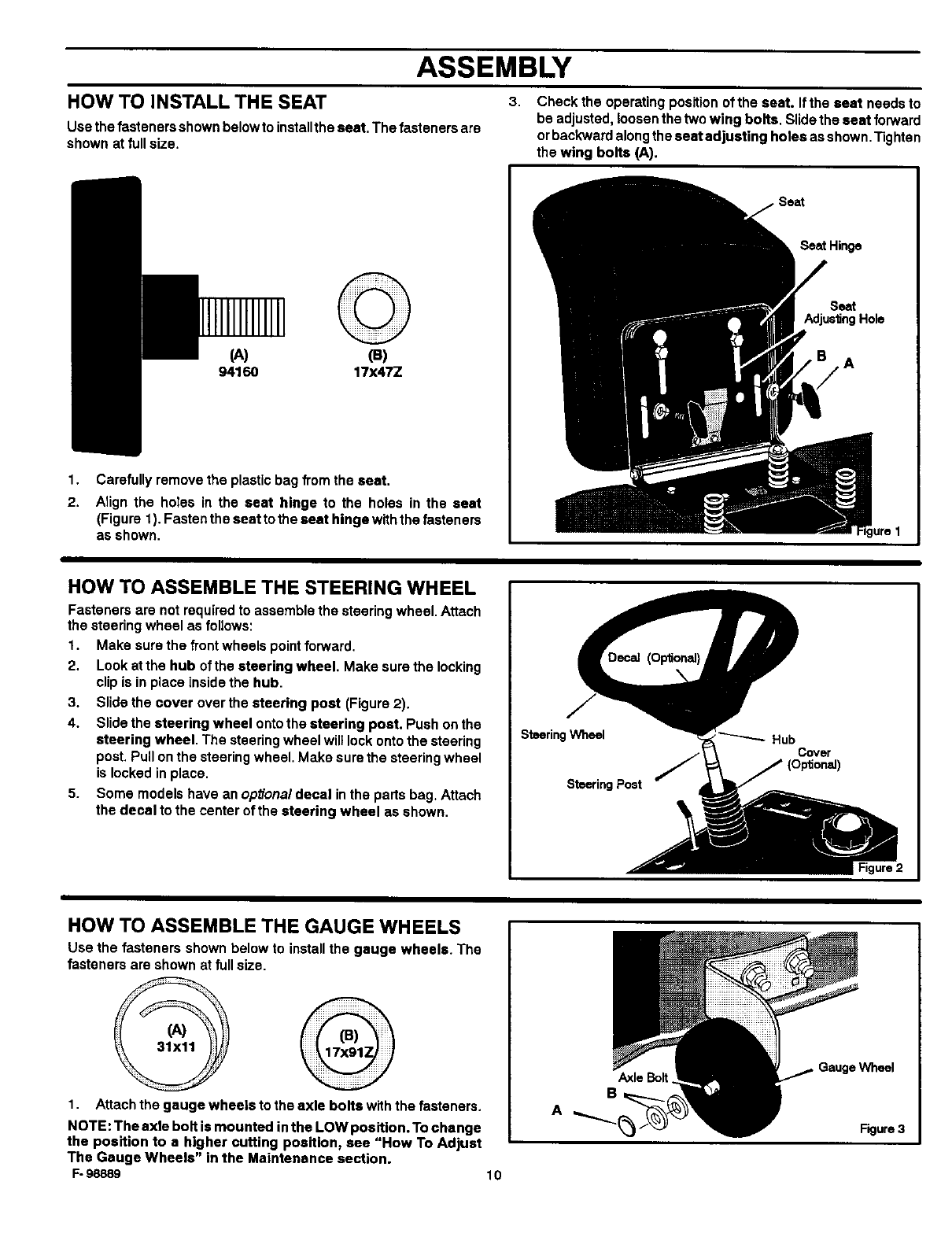
HOW TO INSTALL THE SEAT
Usa the fasteners shown below to installthe seat. The fasteners are
shown at full size.
Check the operating position of the seat. If the seat needs to
be adjusted, loosen the two wing bolts. Slide the seat forward
orbackward along the seat adjusting holes as shown. Tighten
the wing bolts (A).
1.
2.
(A) (a)
94160 17x47Z
Carefully remove the plastic bag from the seat.
Align the holes in the seat hinge to the holes in the seat
(Figure 1). Fasten the seat to the seat hinge withthe fasteners
as shown.
Seat Hinge
Seat
Adjus_ngHole
A
HOW TO ASSEMBLE THE STEERING WHEEL
Fasteners are not required to assemble the steering wheel. Attach
the steering wheel as follows:
1. Make sure the front wheels point forward.
2. Look at the hub of the steering wheel. Make sure the locking
clip is in place Inside the hub.
3. Slide the cover over the steering post (Figure 2).
4. Slide the steering wheel onto the steering post. Push on the
steering wheel. The steering wheel will lock onto the steering
post. Pull onthe steering wheel. Make sure the steering wheel
is locked in place.
5. Some models have an optiona/decal in the parts bag, Attach
the decal to the center of the steering wheel as shown.
SteeringWheel
SteeringPost
Hub Cover
iFigure 2
HOW TO ASSEMBLE THE GAUGE WHEELS
Use the fasteners shown below to install the gauge wheels. The
fasteners are shown at full size.
1. Attach the gauge wheels to the axle bolts with the fasteners.
NOTE: The axle bolt is mounted inthe LOW position. To change
the position to a higher cutting position, see "How To Adjust
The Gauge Wheels" in the Maintenance section.
1=-98889 10
Axle Bolt
B
AFigure 3
ASSEMBLY
MAINTENANCE FREE BATTERY HOW TO CHARGE THE MAINTENANCEFREE BATTERY
IMPORTANT: Before you attach the battery cables to the A
battery, check the battery date. The battery date tells if the &JL
battery must be charged.
1. Check the top of the battery for the location of the battery date 1.
(Figure 4).
2. If the battery is put into service before the battery date, the 2.
battery cables can be attached without charging the battery. 3.
See "How To Install The Battery Cables'.
3. If the battery is put into service after the battery date, the
battery must be charged. See =How To Charge The 4.
Maintenance Free Battery".
WARNING: When you charge the battery, do not
smoke. Keep the battery away from any sparks. The
fumes from the battery acid can cause an explosion.
Remove the battery and battery tray.
Remove the protective caps from the battery terminals.
Use a 12 volt battery charger to charge the battery. Charge at
a rate of 6 amperes for one hour. If you do not have abattery
charger, have en authorized service center charge the battery.
Installthe battery end battery tray. Make sure the positive (+)
terminal is on the left side.
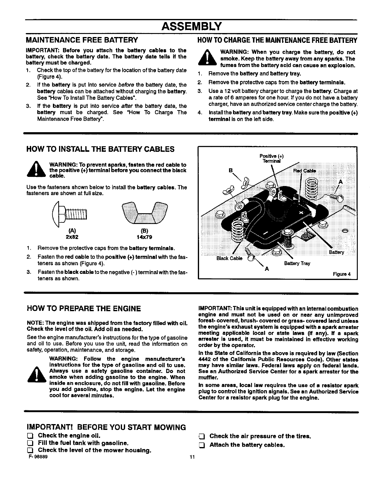
HOW TO INSTALL THE BATTERY CABLES
A WARNING: To prevent sparks, fasten the red cable to
the positive (+) terminal before you connect the black
cable.
Use the fastenersshownbelowto installthe battery cables. The
fastenersare shownatfullsize.
(A)
2X82
1,
2.
3,
(13)
14x79
Remove the protective caps from the battery terminals.
Fasten the red cable to the positive (+) terminal with the fas-
teners as shown (Figure 4),
Fasten the black cable to the negative (-) terminalwith the fas-
teners as shown.
I
B\
Black Cable
PosilJve +)
Term nal
ABatteryTray
I
Figure4
HOW TO PREPARE THE ENGINE
NOTE: The engine was shipped from the factory filled with oil.
Check the level of the oil. Add oil as needed.
See the enginemanufacturer'sinstructionsforthe typeof gasoline
and oilto use. Beforeyou use the unit,read the informationon
safety,operation,maintenance,andstorage,
WARNING: Follow the engine manufacturer's
instructions for the type of gasoline and oil to use.
A lways use a safety gasoline container. Do not
smoke when adding gasoline to the engine. When
inside an enclosure, do not fill with gasoline. Before
you add gasoline, stop the engine. Let the engine
cool for several minutes.
IMPORTANT: This unit is equipped with an internal combustion
engine and must not be used on or near any unimproved
forest- covered, brush- covered or grass- covered land unless
the engine's exhaust system is equipped with a spark arrester
meeting applicable local or state laws (if any). If a spark
arrester is used, it must be maintained in effective working
order by the operator.
In the State of CalIfornia the above is required by law (Section
4442 of the California Public Resources Code). Other states
may have similar laws. Federal laws apply on federal lands.
See an Authorized Service Center for a spark arrester for the
muffler.
In some areas, local law requires the use of a resistor spark
plug to control the ignition signals. See an Authorized Service
Center for a resistor spark plug for the engine.
IMPORTANT! BEFORE YOU START MOWING
[] Checkthe engine oil.
[] Fill the fuel tank with gasoline.
[_ Check the level of the mower housing.
F-98889
Check the air pressure of the tires.
[_ Attach the battery cables.
11
OPERATION
ThrottleConlrol
Lever
Blade Rota_on
Cor_ol
Brake Pedal
U
Lever
Figure 5
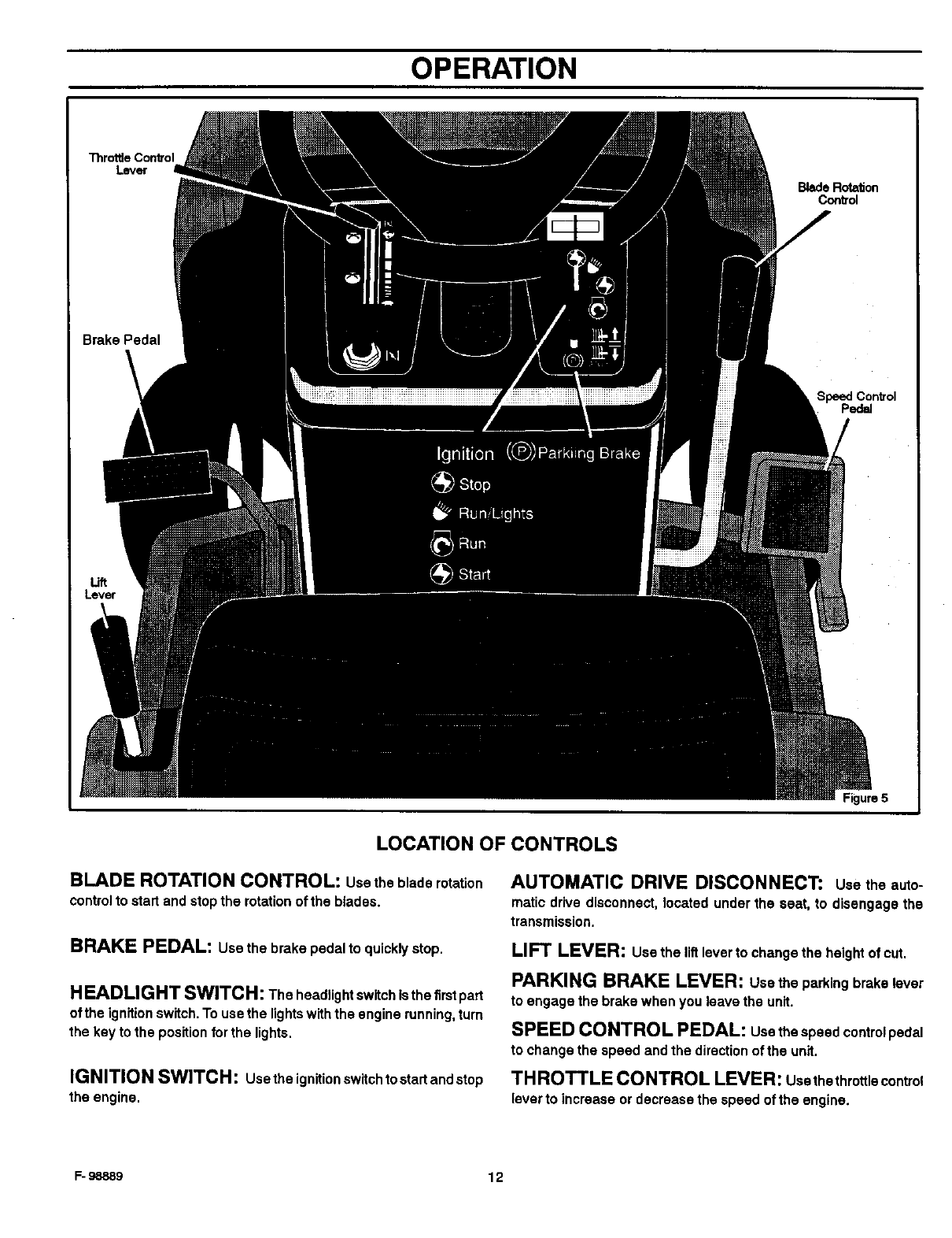
LOCATION OF CONTROLS
BLADE ROTATION CONTROL: usethebladerotation
control to start and stop the rotation of the blades.
BRAKE PEDAL: Use the brake pedal to quickly stop.
H EADLIG HT SWlTCH: The headlight switch is the firstpart
of the ignition switch. To use the lightswith the engine running, tum
the key to the position for the lights.
IGNITION SWITCH: Usetheignitionswitchtostartandstop
the engine.
AUTOMATIC DRIVE DISCONNECT: usetheauto-
maticdrive disconnect, located under the seat, to disengage the
transmission.
LIFT LEVER: use the lift lever to change the height of cut.
PARKING BRAKE LEVER: usatheparkingbrake lever
to engage the brake when you leave the unit.
SPEED CONTROL PEDAL: usethe speed control pedal
to change the speed and the direction of the unit.
THROTTLE CONTROL LEVER: Usethethrottlecontrol
lever to increase or decrease the speed of the engine.
F- 98889 12
OPERATION
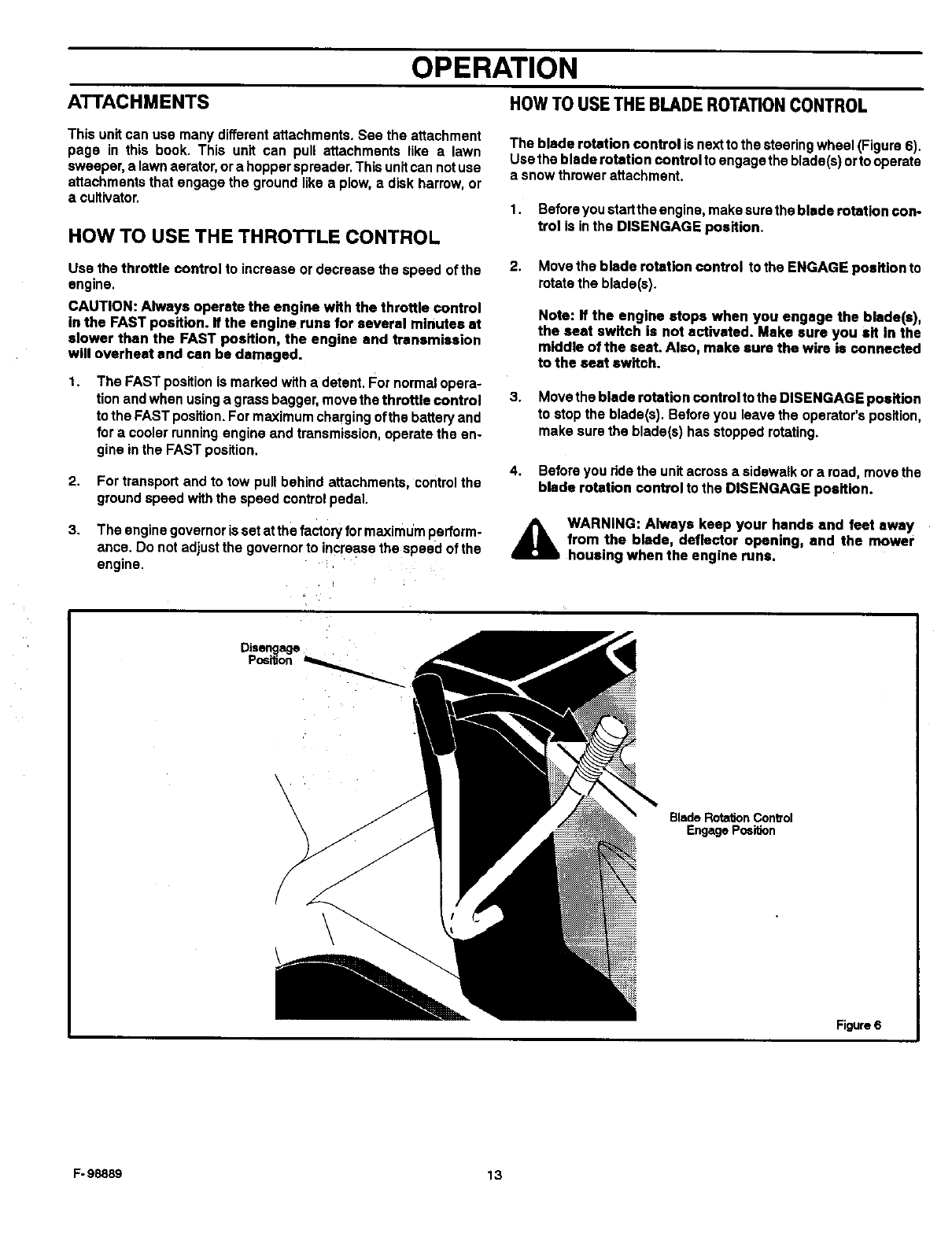
ATTACHMENTS HOWTO USETHE BLADE ROTATIONCONTROL
This unit can use many different attachments. See the attachment
page in this book. This unit can pull attachments like alawn
sweeper, a lawn aerator, ora hopper spreader. This unitcan not use
attachments that engage the ground like a plow, a disk harrow, or
a cultivator.
HOW TO USE THE THROTTLE CONTROL
The blade rotation control is next to the steering wheel (Figure 6).
Use the blade rotation control to engage the blade(s) or to operate
a snow thrower attachment.
1. Before you startthe engine, make sure the blade rotation con-
trol is in the DISENGAGE position.
Use the throttle control to increase or decrease the speed of the
engine.
CAUTION: Always operate the engine with the throttle control
in the FAST position. If the engine runs for several minutes at
slower than the FAST position, the engine and transmission
will overheat and can be damaged.
t, The FAST position is marked with a detent. For normal opera-
tion and when using a grass bagger, move the throttle control
to the FAST position, For maximum charging of the battery and
for a cooler running engine and transmission, operate the en-
gine in the FAST position.
2.
3,
For transport and to tow pull behind attachments, control the
ground speed with the speed control pedal.
The engine governor is set at the factory for maximum pedorm-
ance. Do not adjust the governor to increase the speed of the
engine.
2. Move the blade rotation control to the ENGAGE position to
rotate the blade(s).
Note: If the engine stops when you engage the blade(s),
the seat switch is not activated. Make sure you sit In the
middle of the seat. Also, make sure the wire is connected
to the seat switch.
3. Move the blade rotation control to the DISENGAGE position
to stop the blade(s). Before you leave the operator's position,
make sure the blade(s) has stopped rotating.
4. Before you ride the unit across asidewalk or aroad, move the
blade rotation control to the DISENGAGE position.
_lb WARNING: Always keep your hands and feet away
from the blade, deflector opening, and the mower
housingwhen the engine runs,
Disengage
Position
\
BladeRota_onCon_'ol
EngagePosiOon
Figure 6
F- 98889 13
OPERATION
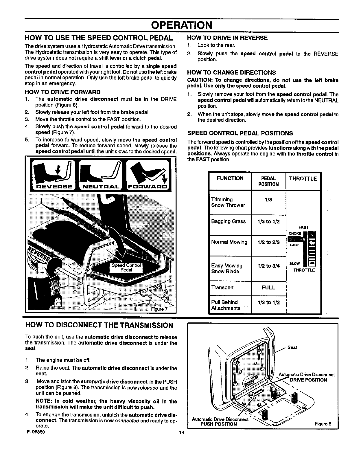
HOW TO USE THE SPEED CONTROL PEDAL
The drive system uses a Hydrostatic Automatic Drive transmission.
The Hydrostatic transmission is very easy to operate. This type of
dr'Ne system does not require a shift lever or a clutch pedal.
The speed and direction of travel is controlled by a single speed
control pedal operated withyour rightfoot, Do not usethe leftbrake
pedal in normal operation. Only use the left brake pedal to quickly
stop in an emergency.
HOW TO DRIVE FORWARD
1. The automatic drive disconnect must be in the DRIVE
position (Figure 8).
2. Slowly release your leftfoot from the brake pedal.
3. Move the throttle controlto the FAST position.
4. Slowly push the speed control pedal forward to the desired
speed (Figure 7).
5. To increase forward speed, slowly move the speed control
pedal forward. To reduce forward speed, slowly release the
speed control pedal until the unit slows to the desired speed.
HOW TO DRIVE IN REVERSE
1. Lookto the rear.
2. Slowly push the speed control pedal to the REVERSE
position.
HOW TO CHANGE DIRECTIONS
CAUTION: To change directions, do not use the left brake
pedal. Use only the speed control pedal.
1. Slowly remove your foot from the speed control pedal. The
speed control pedal will automatically returnto the NEUTRAL
position.
2. When the unit stops, slowly move the speed control pedal to
the desired direction.
SPEED CONTROL PEDAL POSITIONS
The forward speed is controlled bythe position ofthe speed control
pedal. The following chart provides functions along with the pedal
positions. Always operate the engine with the throttle control in
the FAST position.
FUNCTION
Trimming
Snow Thrower
Bagging Grass
Normal Mowing
Easy Mowing
Snow Blade
Transport
PEDAL THRO'I-I'LE
POSITION
1/3
1/3 to 1/2
FAST
,/2to 3 l
1/2 to 3/4 SLOW_ ____
THROTTLE
FULL
1/3 to 1/2
Pull Behind
:igure7 Attachments
HOW TO DISCONNECT THE TRANSMISSION
To push the unit, use the automatic drive disconnect to release
the transmission. The automatic drive disconnect is under the
seat.
1. The engine must be off.
2. Raise the seat. The automatic drive disconnect is under the
seat.
3. Move and latchthe automatic drive disconnect inthe PUSH
position (Figure 8). The transmission is now released and the
unit can be pushed.
NOTE: In cold weather, the heavy viscosity oil in the
transmission will make the unit difficult to push.
4. To engage the transmission, unlatch the automatic drive dis-
connect. The transmission is now connected and ready to op-
erate.
F- 98889 14
Automatic Drive Disconnect
PUSH POSITION Figure 8
OPERATION
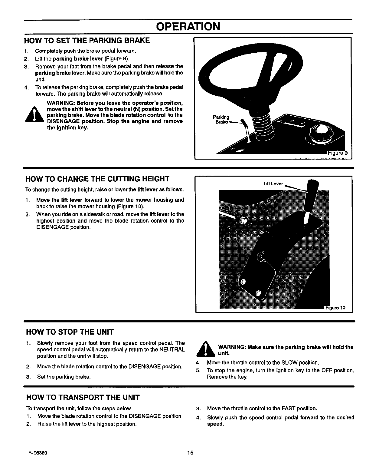
HOW TO SET THE PARKING BRAKE
1. Completely push the brake pedal forward.
2. Lift the parking brake lever (Figure 9).
3, Remove your foot from the brake pedal and then release the
parking brake lever. Make sure the parking brake will holdthe
unit.
4. To release the parking brake, completely push the brake pedal
forward. The parking brake will automatically release.
WARNING: Before you leave the operator's position,
l& move the shHt lever to the neutral _1) position. Set the
parking brake. Move the blade rotation control to the
DISENGAGE position. Stop the engine and remove
the ignition key.
Parking
HOW TO CHANGE THE CUTTING HEIGHT
To change the cutting height, raise or lower the lift lever as follows.
1. Move the lift lever forwardto lowerthe mowerhousingand
backto raisethe mowerhousing(Figure10).
2. When yourideona sidewalkorroad,movethe liftleverto the
highestpositionand move the blade rotationcontrolto the
DISENGAGE position.
LiftLever
HOW TO STOP THE UNIT
1. Slowly remove your foot from the speed control pedal, The
speed control pedal will automatically return to the NEUTRAL
position and the unit will stop.
2. Move the blade rotation control to the DISENGAGE position,
3, Set the parking brake,
_hb ARNING: Make sure the parking brake will hold the
unit.
4. Movethe throttlecontrolto the SLOWposition.
5. Tostopthe engine,turnthe ignitionkey to the OFF position.
Removethe key.
HOW TO TRANSPORT THE UNIT
To transport the unit,follow the steps below.
1. Move the blade rotation control to the DISENGAGE position
2. Raise the lift lever to the highest position,
3. Move the throttle control to the FAST position.
4. Slowly push the speed control pedal forward to the desired
speed.
F- 98889 15
OPERATION
HOW TO OPERATEWITH THE MOWER HOUSING
A
1,
2.
3.
WARNING: The deflector is a safety device. Do not re-
move the deflector. The deflector forces the dis-
charged material toward the ground. Always keep the
deflector in the down position. If the deflector is dam-
aged, replace the deflector with an original equipment
part from an authorized service center.
Start the engine.
Release the parking brake.
Move the lift lever to a height of cut position. In high or thick
grass, cut the grass inthe highest position first and then lower
the mower housing to a lower position.
4. Move the throttle control to the SLOW position.
5. Move the blade rotation control to the ENGAGE position.
6. Move the throttle control to the FAST position.
7. Slowly push the speed control pedal to the desired speed.
NOTE: When you mow in heavy grass or mow with a grass
bagger, use a slow forward speed.
8. Make sure the level of cut set at the factory is stillcorrect. After
you mow a short distance, look at the area that was cut. Ifthe
mower housing does not cut level, see the instructionson "How
To Level The Mower Housing" in the Maintenance section.
CAUTION: Do not operate with the mower housing in the
LEVEL ADJUSTMENT position. If you operate In the A4_
LEVEL ADJUSTMENT position, the mower housing and all
blades can be damaged.
WARNING: For better control of the unit, always
select a safe speed.
HOW TO OPERATE THE UNIT ON HILLS
AWARNING: Do not ride up or down slopes that are too 2.
steep to back straight up, Never ride the unit across
a slope. See the "Slope Guide" in the back of this 3.
book for information on how to check slopes.
HOW TO OPERATE ON A HILL
1. Controlthe speed only withthe speed controlpedal. Do not use
the brake pedal on a hill.
2. To help prevent an accident, slowly move the speed control
pedal Avoid sudden turns or changes in speed.
3. To reduce forward speed when going down a hill,slowly release
the speed control pedal until the unit slows to the desired
speed.
HOW TO STOP ON A HILL
1. Avoid stopping on a hill. If you must quickly stop inan emergen-
cy, remove your right foot from the speed control pedal and
quickly depress the left brake pedal.
Set the parking brake.
Before you dismount fromthe seat, move the throttle control to
SLOW position, move the blade rotation controlto the DISEN-
GAGED position, turn offtha engine and sat the parking brake.
HOW TO START OPERATION ON A HILL
1. Start the engine
2. Move the blade rotation control to the ENGAGED position.
3. Move the throttle control to the FAST position.
4. Depress the brake pedal and release the parking brake. As you
release the parking brake, push the speed controlpedal to the
desired speed.
A WARNING: Slowly push the speed control pedal as
you release the parking brake. The parking brake
must be disengaged before the speed control pedal
is able to engage the transmission.
F- 98889 16
OPERATION
BEFORE STARTING THE ENGINE
CHECK THE OIL
NOTE: The engine was shipped from the factory filled with oil.
Check the level of the oil. Add oil as needed. See the engine
manufacturer's instructions for the type of gasoline and oil to
use.
1. Make sure the unit is level.
NOTE: Do not check the level of the oil while the engine
rune.
CAUTION: A mixture of alcohol (ethanol or methanol) end
gasoline (called gasohol), will attract moisture and cause acid
deposits during storage. While the unit is in storage,the acids
inthe fuel can damage the fuel system.
To preventengine problemswiththe fuelsystem, emptythe fuel
systembeforestorageof30 days orlongeras follows.
1. Drain the fuel tank.
2. Start the engine. Let the engine run until the fuel lines and the
carburetor are empty.
2. Check the oil. Follow the procedure inthe engine manufactur- 3. After storage, make sure you use fresh fuel. See the storage
er's instructions, instructionsfor additional information.
3. If necessary, add oil until the oil reaches the FULL mark on the
dipstick. The quantity of oil needed from ADD to FULL is shown
on the dipstick. Do not add too much oil.
4. Neveruseenginecleanerorcarburetorcleanerinthefuel tank
orpermanentdamage can occur.
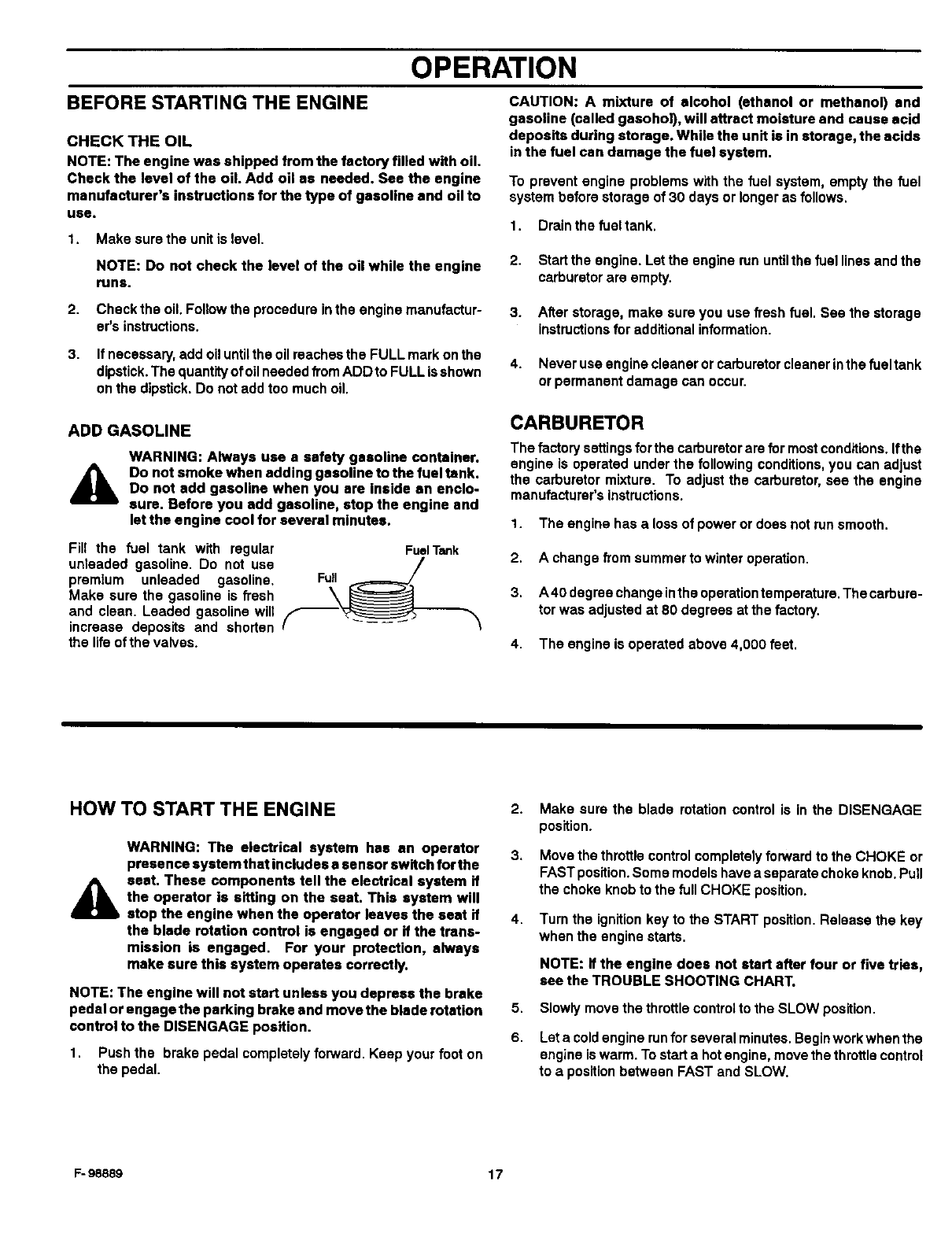
ADD GASOLINE
AWARNING: Always use a safety gasoline container.
Do not smoke when adding gasoline to the fuel tank.
Do not add gasoline when you are inside an enclo-
sure. Before you add gasoline, stop the engine and
let the engine cool for several minutes.
Fill the fuel tank with regular
unteaded gasoline. Do not use
premium unleaded gasoline,
Make sure the gasoline is fresh
and clean. Leaded gasoline will
increase deposits and shorten
the life of the valves.
Full
Fuel Tank
CARBURETOR
The factory settings for the carburetor are for most conditions. Ifthe
engine Is operated under the following conditions, you can adjust
the carburetor mixture. To adjust the carburetor, see the engine
manufacturer's instructions.
1. The engine has a loss of power or does not run smooth.
2. A change from summer to winter operation.
3. A40 degrae change inthe operation temperature. The carbure-
tor was adjusted at 80 degrees at the factory.
4. The engine is operated above 4,000 feet.
HOW TO START THE ENGINE
A
WARNING: The electrical system has an operator
presence system that includes a sensor switch for the
seat. These components tell the electrical system if
the operator is sitting on the seat. This system will
stop the engine when the operator leaves the seat if
the blade rotation control is engaged or if the trans-
mission is engaged. For your protection, always
make sure this system operates correctly.
2.
3.
4.
NOTE: The engine will not start unless you depress the brake
pedal or engage the parking brake and move the blade rotation 5.
control to the DISENGAGE position. 6.
1. Push the brake pedal completely forward. Keep your foot on
the pedal.
Make sure the blade rotationcontrolis inthe DISENGAGE
position.
Move the throttle control completely forward to the CHOKE or
FAST position. Some models have a separate choke knob. Pull
the choke knob to the full CHOKE position.
Turn the ignition key to the START position. Release the key
when the engine starts.
NOTE: if the engine does not start after four or five tries,
see the TROUBLE SNOOTING CHART.
Slowly move the throttle control to the SLOW position.
Let a cold engine run for several minutes. Beginwork when the
engine is warm. To start a hot engine, move the throttle control
to a position between FAST and SLOW.
F- 98889 17
OPERATION
OPERATING TIPS
1.
2.
3.
4.
Checkthe bladerotationcontrolfor correctadjustment.Forthe
blade(s)to disengagecorrectly,the adjustment must be cor-
rect.
Before you use the unit, check the oil inthe engine and add oil
if necessary.
If the enginewillnotstart,firstmakesurethe wire is attached
to the sparkplug.
Make sureallthe beltsare insideallthe beltguides.See the in-
structionson howto removeand installthe motiondriveand
mower drive belts.
5.
6.
7.
8.
Before you make an inspection, adjustment (except for the car-
buretor) or repair, make sure the wire from the spark plug is dis-
connected.
For longer lifeof the battery on electric start models, charge the
battery every three months.
Use the speedcontrolpedalto changethe groundspeed,not
the throttlecontrol.
Belt noise can occur when the blade is engaged. This noise is
normal and does not affect the operation of the unit.
MOWING AND BAGGING TIPS
1. For a lawn to look better, check the cutting level of the mower
housing. See =How To Level The Mower Housing" in the Main-
tenance section.
2.
3.
4.
For the mower housing to cut level, make sure the tires have
the correct amount of air pressure.
Every time you use the unit,check the blade. Ifthe blade is bent
or damaged, immediately replace the blade. Also, make sure
the nut for the blade is tight.
Keepthe blade(s)sharpened.Wornbladeswillcausetheends
of the grassto turnbrown.
5.
6.
7.
8.
9.
Do not cut orbag grass that iswet. Wet grass will not discharge
correctly. Let the grass dry before cutting.
Use the left side of the mower housing to trim near an object.
Dischargethe cutgrassontothe mowedarea.The resultisa
moreeven dischargeof cutgrass.
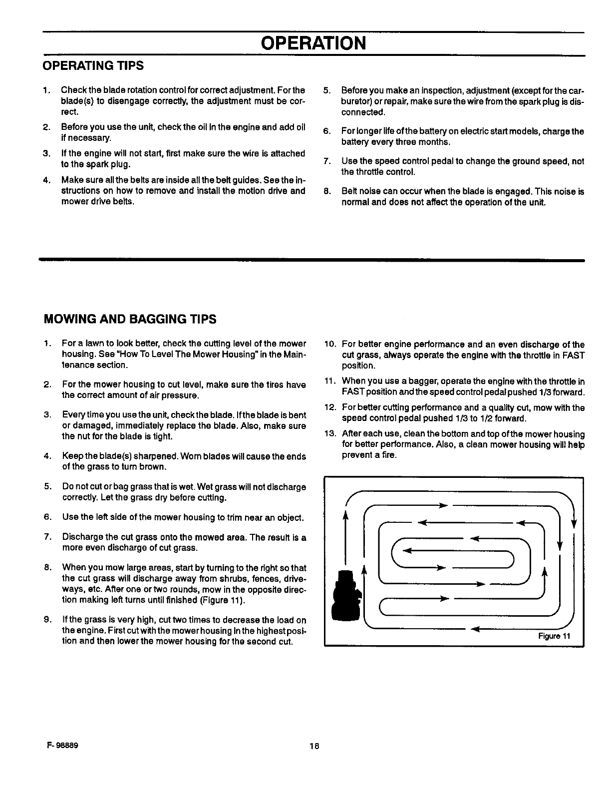
When you mow large areas, start by turning to the rightso that
the cut grass will discharge away from shrubs, fences, drive-
ways, etc. After one ortwo rounds, mow in the opposite direc-
tion making leftturns until finished (Figure 11).
Ifthe grass is very high, cuttwo times to decrease the load on
the engine. First cutwiththe mower housing inthe highest posi-
tion and then lower the mower housing for the second cut.
10.
11.
12.
13.
For better engine performance and an even discharge of the
cut grass, always operate the engine with the throttle in FAST
position.
When you use a bagger, operate the engine with the throttle in
FAST position and the speed controlpedal pushed 1/3 forward.
For better cutting performance and a quality cut, mow with the
speed control pedal pushed 1/3 to 1/2 forward.
After each use, clean the bottom and top ofthe mower housing
for better performance. Also, aclean mower housing will help
prevent a fire.
(
J
Figure11
F- 98889 18
OPERATION
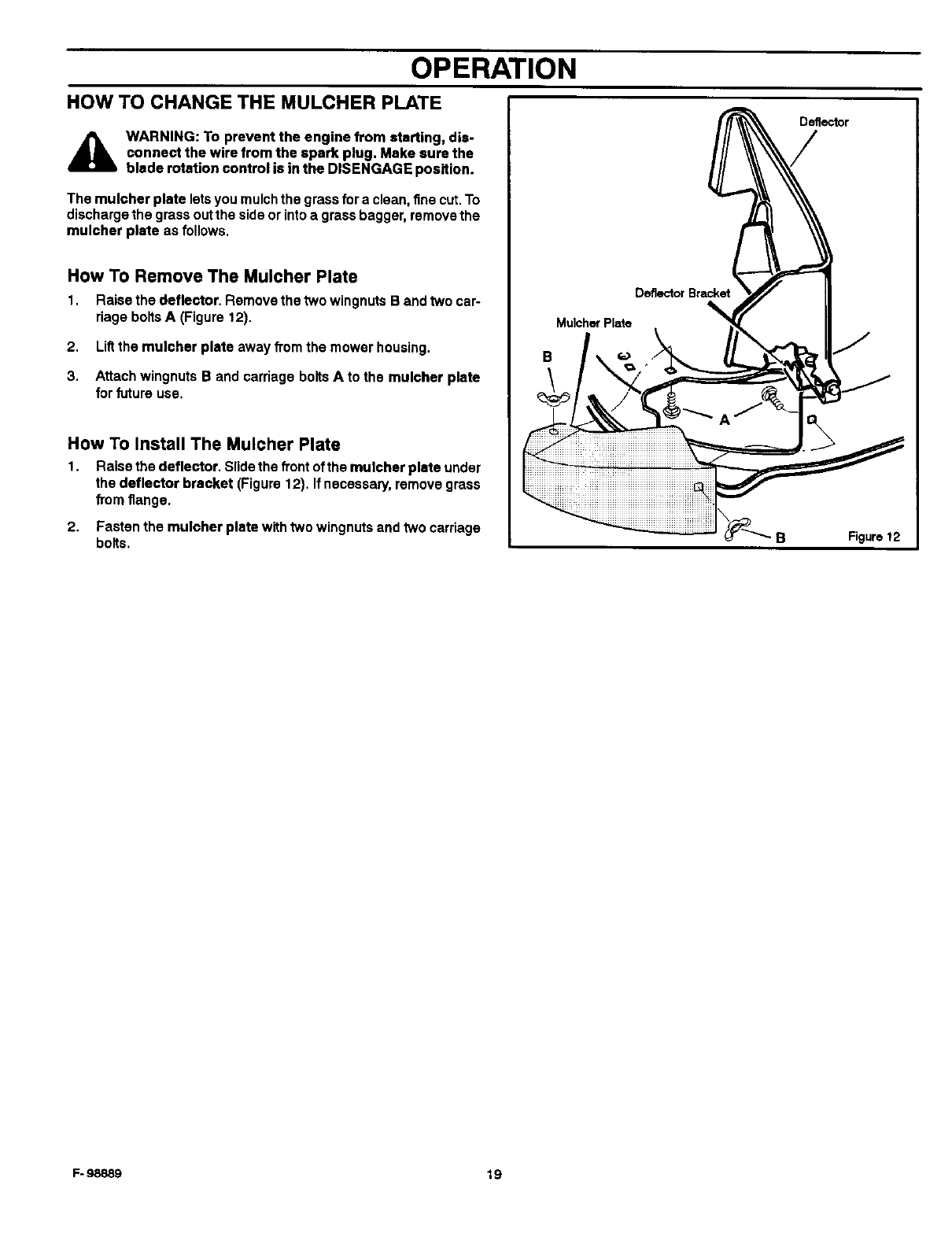
HOW TO CHANGE THE MULCHER PLATE
A WARNING: To prevent the engine from starting, dis-
connect the wire from the spark plug. Make sure the
blade rotation control is in the DISENGAGE position.
The mulcher plate lets you mulch the grass for a clean, fine cut. To
discharge the grass out the side or into a grass bagger, remove the
rnulcher plate as follows.
How To Remove The Mulcher Plate
1. Raise the deflector. Remove the two wingnuts B and two car-
riage bolts A (Figure t2).
2. Liftthe mulcher plate away from the mower housing.
3. Attach wingnuts B and carriage bolts A to the mulcher plate
for future use.
How To Install The Mulcher Plate
1. Raise the deflector. Slide the front of the mulcher plate under
the deflector bracket (Figure 12). Ifnecessary, remove grass
fTom flange.
2. Fasten the mulcher plate with two wingnuts and two carriage
bolts.
DeflectorBracket
Mulche_Plate
B
Deflector
B Figure 12
F- 98889 19
MAINTENANCE
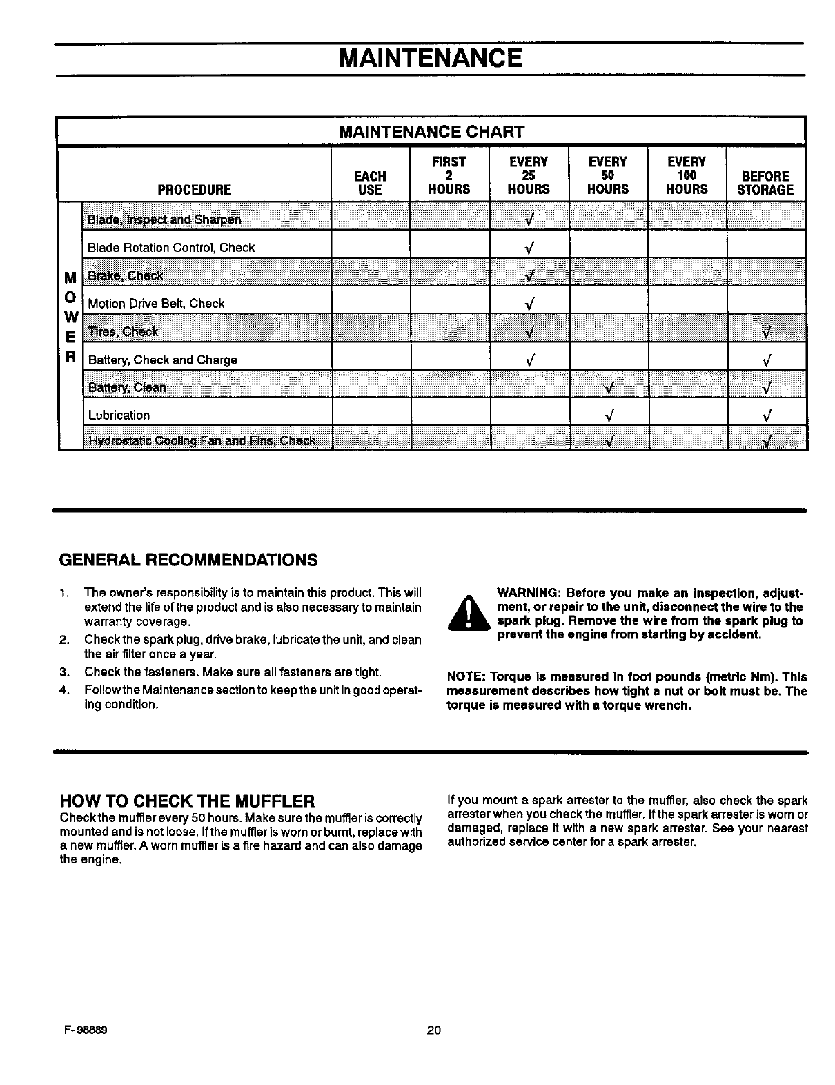
MAINTENANCE CHART
PROCEDURE
FIRST EVERY EVERY EVERY
EACH 2 2S 50 100
USE HOURS HOURS HOURS HOURS BEFORE
STORAGE
M
O
W
E
R
Blade Rotation Control, Check
Motion Drive Belt, Check
Battery, Check and Charge
¢
¢
Lubrication _/
¢
¢
GENERAL RECOMMENDATIONS
1. The owner's responsibility is to maintain this product. This will
extend the life of the product and is also necessary to maintain
warranty coverage.
2. Check the spark plug, drive brake, lubricate the unit,and clean
the air filter once a year.
3. Check the fasteners. Make sure all fasteners are tight.
4. Followthe Maintenance section to keep the unit ingood operat-
ing condition.
WARNING: Before you make an Inspection, adjust-
A ment, or repair to the unit, disconnect the wire to the
spark plug. Remove the wire from the spark plug to
prevent the engine from starting by accident.
NOTE: Torque Is measured in foot pounds (metric Nm). This
measurement describes how tight a nut or bolt must be. The
torque is measured with a torque wrench.
HOW TO CHECK THE MUFFLER
Check the mufflerevery 50 hours. Make sure the muffler is correctly
mounted and is not loose. Ifthe muffleris worn orburnt, replace with
anew muffler. A worn muffler is a fire hazard and can also damage
the engine.
If you mount aspark arrester to the muffler, also check the spark
arrester when you check the muffler. Ifthe spark arrester is worn or
damaged, replace it with anew spark arrester. See your nearest
authorized service center for a spark arrester.
F- 98889 20
MAINTENANCE
INSPECT BLADE
WARNING: Before you inspect or remove the blade,
A disconnect the wire to the spark plug. it the blade h_s
an object, stop the engine. Check the unit for dam-
age. The blade has sharp edges. When you hold the
blade, use gloves or cloth material to protect your
hands.
If you keep the blade sharp and inspect the blade for damage, the
blade will cut better and be more safe to operate. Frequently check
the blade for excessive wear, cracks, or other damage. Frequently
check the nut that holds the blade. Keep the nut tight. If the blade
hitsan object, stopthe engine. Disconnectthe wire tothe spark plug.
See if the blade is bent or damaged. Check the blade adapter for
damage. Before you operate the unit, replace damaged parts with
original equipment parts. See the authorized service center in your
area. Every three years, have an authorized service person inspect
the blade or replace the old blade with an original equipment part.
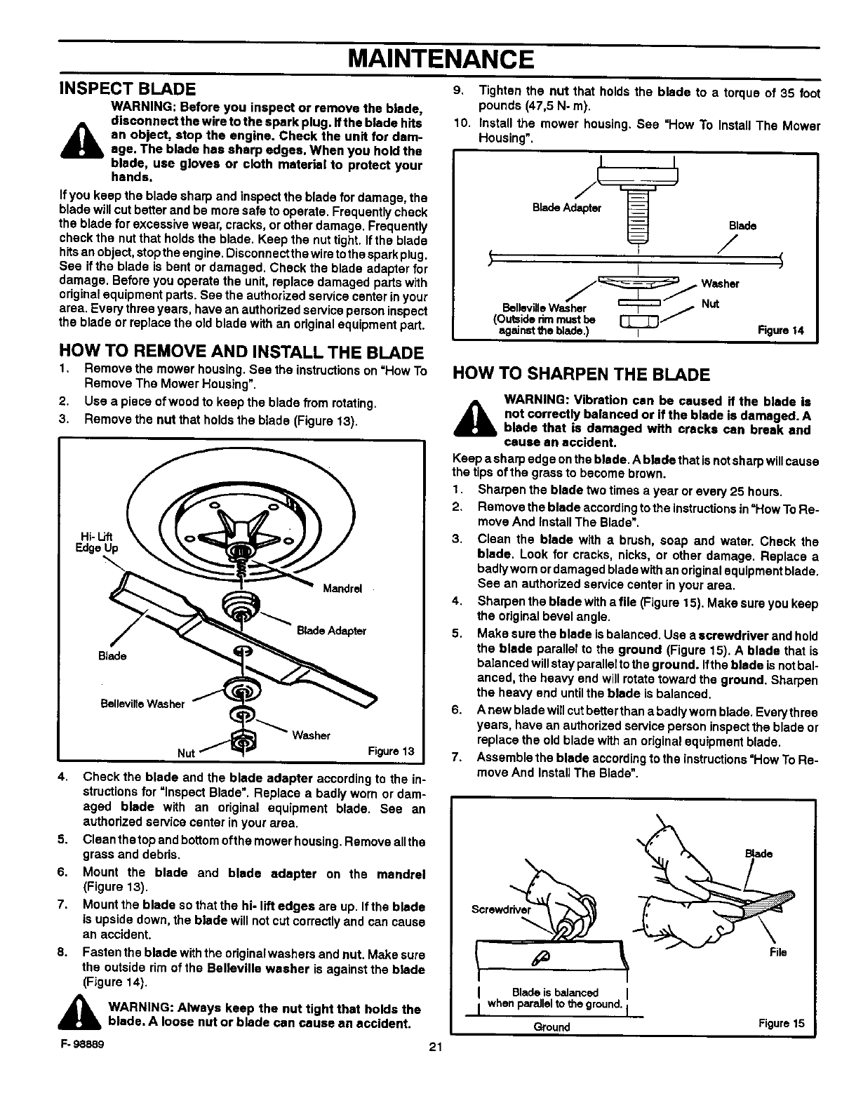
HOW TO REMOVE AND INSTALL THE BLADE
1. Remove the mower housing. See the instructions on =How To
Remove The Mower Housing".
2. Use a piece of wood to keep the blade from rotating.
3. Remove the nut that holds the blade (Figure 13).
Hi- Lift
Edge Up
Mandrel
EtellevillaWasher
Figure13
4. Check the blade and the blade adapter according to the in-
structions for =Inspect Blade'. Replace a badly worn or dam-
aged blade with an original equipment blade. See an
authorized service center in your area.
5. Clean thetop and bottom oftha mower housing. Remove allthe
grass and debris.
6. Mount the blade and blade adapter on the mandrel
(Figure 13).
7. Mount the blade so that the hi- lift edges are up. If the blade
is upside down, the blade will not cut correctly and can cause
an accident.
8. Fasten the blade with the originalwashers and nut. Make sure
the outside rim of the Belleville washer is against the blade
(Figure 14).
AWARNING: Always keep the nut tight that holds the
blade. A loose nut or blade can cause an accident.
9. Tighten the nut that holds the blade to a torque of 35 foot
pounds (47,5 N- m).
10. Install the mower housing. See =How To Install The Mower
Housing".
BladeAdapter
Blade
/
7Washer
BellavillaWasher t-..T--_ jNut
(Outsiderimmustbe [_
againstthe blade.) I Figure14
HOW TO SHARPEN THE BLADE
A WARNING: Vibration can be caused if the blade is
not correctly balanced or if the blade is damaged. A
blade that is damaged with cracks can break and
cause an accident.
Keep a sharp edge on the blade. A blade that isnot sharp will cause
the tips of the grass to become brown.
1. Sharpen the blade two times a year or every 25 hours.
2. Remove the blade according to the instructions in=How To Re-
move And Install The Blade".
3. Clean the blade with a brush, soap and water. Check the
blade. Look for cracks, nicks, or other damage. Replace a
badly worn or damaged blade withan originalequipment blade.
See an authorized service center in your area.
4. Sharpen the blade with a file (Figure t 5). Make sure you keep
the original bevel angle.
5. Make sure the blade is balanced. Use a screwdriver and hold
the blade parallel to the ground (Figure 15). A blade that is
balanced will stay parallel to the ground. Ifthe blade is not bal-
anced, the heavy end will rotate toward the ground. Sharpen
the heavy end until the blade is balanced.
6. A new blade willcut betterthan a badly worn blade. Everythree
years, have an authorized service person inspect the blade or
replace the old blade with an original equipment blade.
7. Assemble the blade according to the Instructions=How To Re-
move And Install The Blade".
Screwdriver
File
I Blade is balanced I
I when parallel to the ground. I
Ground Figure 15
F- 98889 21
MAINTENANCE
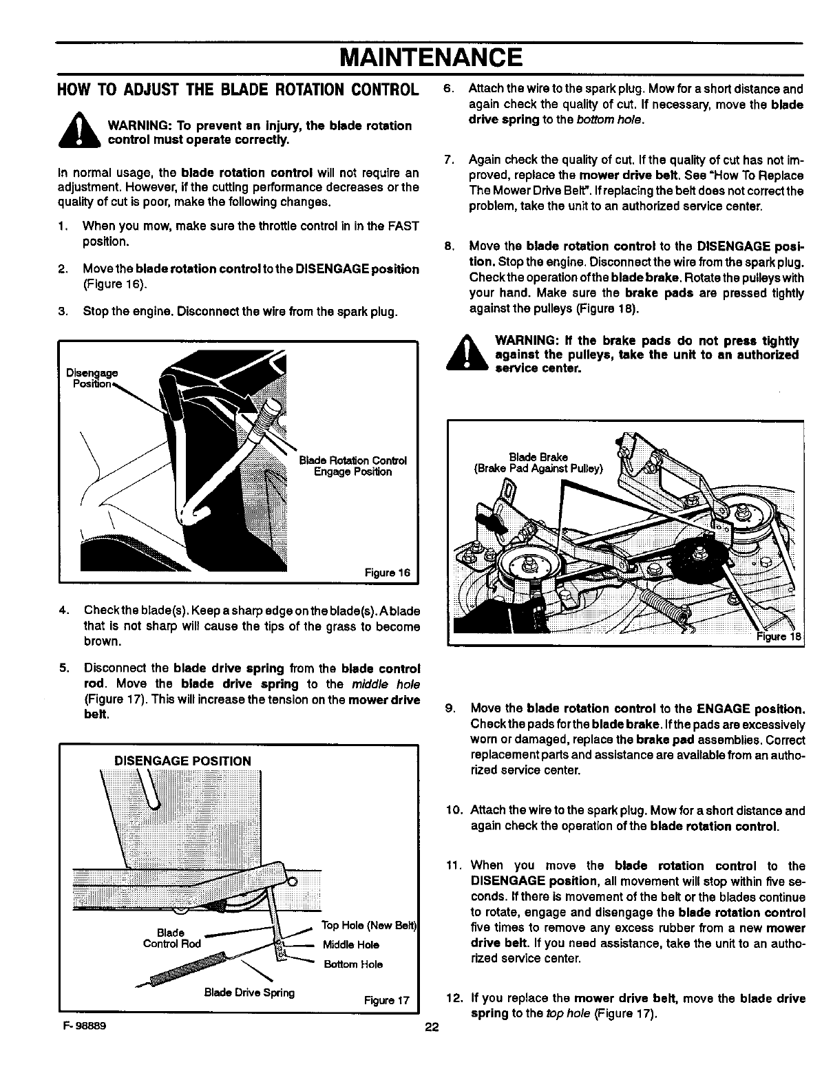
HOW TO ADJUST THE BLADE ROTATIONCONTROL
A ARNING: To prevent an injury, the blade rotation
control must operate correctly.
In normal usage, the blade rotation control will not require an
adjustment. However, if the cutting performance decreases or the
quality of cut is poor, make the following changes.
1. When you mow, make sure the throttle control in in the FAST
position.
2. Move the blade rotation control to the DISENGAGE position
(Figure 16).
3. Stop the engine. Disconnect the wire from the spark plug.
6. Attach the wire to the spark plug. Mow for a short distance and
again check the quality of cut. If necessary, move the blade
drive spring to the bottom hole.
7, Again check the quality of cut. If the quality of cut has not im-
proved, replace the mower drive belt. See =How To Replace
The Mower Drive Belt". If replacing the belt does not correctthe
problem, take the unit to an authorized service center.
8, Move the blade rotation control to the DISENGAGE posi-
tion. Stop the engine. Disconnect the wire from the spark plug.
Check the operation ofthe blade brake. Rotate the pulleys with
your hand. Make sure the brake pads are pressed tightly
against the pulleys (Figure 18).
Disengage
Engage Po6ition
Figure 16
4. Checkthe blade(s). Keep a sharp edge on the blade(s),Ablade
that is not sharp will cause the tips of the grass to become
brown.
A ARNING: If the brake pads do not press tightly
against the pulleys, take the unit to an authorized
service center.
Blade Brake
(Brake Pad Against Pulley)
5,
F- 98889
Disconnect the blade drive spring from the blade control
rod. Move the blade drive spring to the middle hole
(Figure 17). This will increase the tension onthe mower drive
belt.
DISENGAGE POSITION
Blade TopHole(NewBelt)
ControlRod MiddleHole
BladeDriveSp_ing Figure17
9,
10.
11.
12.
22
Move the blade rotation control to the ENGAGE position.
Check the pads forthe blade brake. Ifthe pads are excessively
worn or damaged, replace the brake pad assemblies. Correct
replacement parts and assistance are available from an autho-
rized service center.
Attach the wire to the spark plug. Mow for a short distance and
again check the operation of the blade rotation control.
When you move the blade rotation control to the
DISENGAGE position, all movement will stop within five se-
conds. If there is movement of the belt orthe blades continue
to rotate, engage and disengage the blade rotation control
five times to remove any excess rubber from a new mower
drive belt. If you need assistance, take the unit to an autho-
rized service center.
If you replace the mower drive belt, move the blade drive
spring to the top hole (Figure 17).
MAINTENANCE
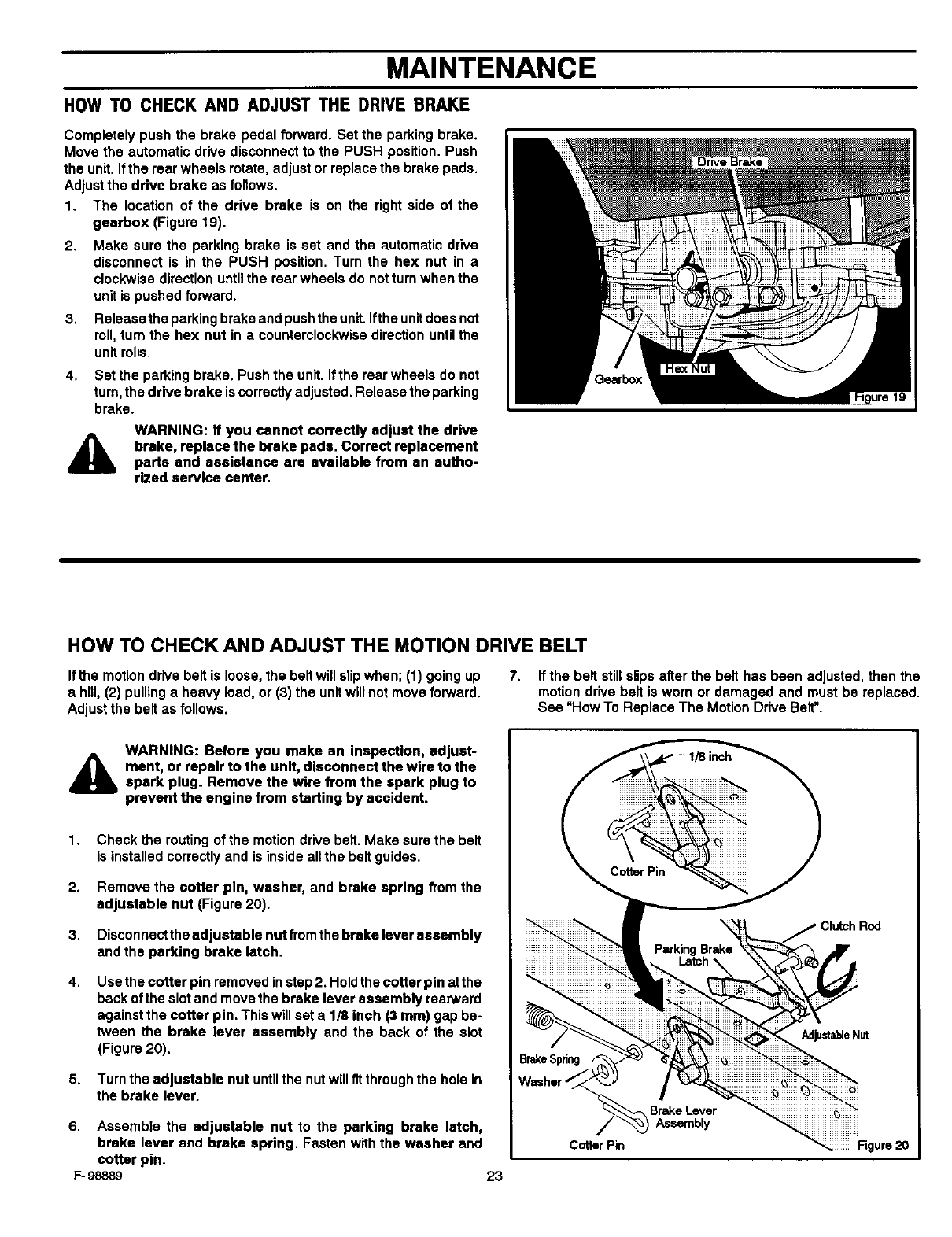
HOW TO CHECK AND ADJUST THE DRIVE BRAKE
Completely push the brake pedal forward. Set the parking brake.
Move the automatic drive disconnect to the PUSH position. Push
the unit. Ifthe rear wheels rotate, adjust or replace the brake pads.
Adjust the drive brake as follows.
1. The location of the drive brake is on the right side of the
gearbox (Figure 19).
2,
3.
4.
Make sure the parking brake is set and the automatic drive
disconnect is in the PUSH position. Turn the hex nut in a
clockwise direction until the rear wheels do not turn when the
unit is pushed forward.
Release the parking brake and push the unit. Ifthe unit does not
roll, turn the hex nut in a counterclockwise direction until the
unit rolls.
Set the parking brake. Push the unit. Ifthe rear wheels do not
turn, the drive brake is correctly adjusted. Release the parking
brake.
AWARNING: If you cannot correctly adjust the drive
brake, replace the brake pads. Correct replacement
parts and assistance are available from an autho-
rized service center.
HOW TO CHECK AND ADJUST THE MOTION DRIVE BELT
Ifthe motion drive belt is loose, the belt will slip when; (1) going up
ahill, (2) pulling a heavy load, or (3) the unit will not move forward.
Adjust the belt as follows.
7. Ifthe belt still slips after the belt has been adjusted, then the
motion drive belt is worn or damaged and must be replaced.
See "How To Replace The Motion Drive Belt".
AWARNING: Before you make an inspection, adjust-
ment, or repair to the unit, disconnect the wire to the
spark plug. Remove the wire from the spark plug to
prevent the engine from starting by accident.
1,
2.
3.
4.
5.
Check the routing of the motion drive belt. Make sure the belt
is installed correctly and is inside allthe belt guides.
Remove the cotter pin, washer, and brake spring from the
adjustable nut (Figure 20).
Disconnectthe adjustable nutfromthe brakeleverassembly
andthe parking brake latch.
Use the cotter pin removed instep 2. Hold the cotter pin at the
back of the slot and move the brake lever assembly rearward
against the cotter pin, This will set a 1/8 inch (3 mm) gap beo
tween the brake lever assembly and the back of the slot
(Figure 20),
Turn the adjustable nut until the nut will fit through the hole in
the brake lever.
6. Assemble the adjustable nut to the parking brake latch,
brake lever and brake spring, Fasten with the washer and
cotter pin.
F- 98889 23
BrakeSpnng
Cotter Pin
Clutch Rod
AdjustableNat
Brake Lever iiiiiiiiiiiiiiiiiiiiiiii_iiiiiii
Assembly
_iiiiiii Figure 20
MAINTENANCE
HOW TO ADJUST THE SPEED CONTROL PEDAL
If the unit will not go into REVERSE or if the unit moves very slowly
in REVERSE, adjust the speed control pedal as follows.
1. Stop the engine.
2. Set the parking brake.
3. Remove the hair pin from the adjuster nut (Figure 21). Dis-
connect the adjuster nut from the yoke assembly.
4. Rotate the adjuster nut one turn in the direction shown in
Figure 21.
NOTE: Too much adjustment will cause REVERSE speed
to be too fast and the FORWARD speed to be reduced.
5. Attach the adjuster nut to the yoke assembly withthe hair pin.
6. To chsckthe adjustment, drive the unit. If the adjustment is cor-
rect, the unit will now go into REVERSE.
IMPORTANT: If you need assistance, go to the nearest
Authorized Service Center. They have the equipment and
experience to make the adjustment.
_-YokeAssemb_
AdjusterNut
SpeedCor_ol Pedal
Figure 21
MAINTENANCE FREE BATTERY
HOW TO REMOVE THE BATTERY
Tochargeorcleanthe battery, removethe batteryfrom the unitas
follows.
AWARNING: To prevent sparks, disconnect the black
battery cable from the negative (-) terminal before you
disconnect the red cable.
WARNING: The battery contains sulfuric acid which is
harmful to the skin, eyes and clothing. If the acid gets
on the body or clothing, wash with water.
1. Disconnect the black cable from the negative (-) terminal
(Figure 22).
2. Disconnect the red ceble from the positive (+) terminal.
3. Lift the battery tray and the battery out of the unit.
HOW TO CLEAN THE BATTERY
1. Remove the battery.
2. Wash the battery with a solution of one gallon ofwater and four
tablespoons of baking soda (sodium bicarbonate). Make sure
the solution does not get into the battery cells.
3. Clean the terminals and the ends of the cables with a wire
brush.
4. Install the battery.
5. To prevent corrosion, apply grease to the battery terminals.
1. Before you charge the battery, remove the battery.
2. To charge the battery, use a 12 volt battery charger. Charge at
a rate of6 amperes for 1 hour.
3. Install the battery.
,_ WARNING: To prevent sparks, fasten the red cable to
the positive (+) terminal before you connect the black
cable.
4. Fasten the red cable to the positive (+) terminal with the fas-
teners as shown.
5. Fasten the black cable toths negative (-) terminalwith the fas-
teners as shown.
iPositive +)
Term nal I
HOW TO CHARGE THE BATTERY
_IL WARNING: When you charge the battery, do not
smoke. Keep the battery away from any sparks. The
fumes from the battery acid can cause an exploslon.
F- 98889 24
Battery Tray
Carriage Bolt Figure 22
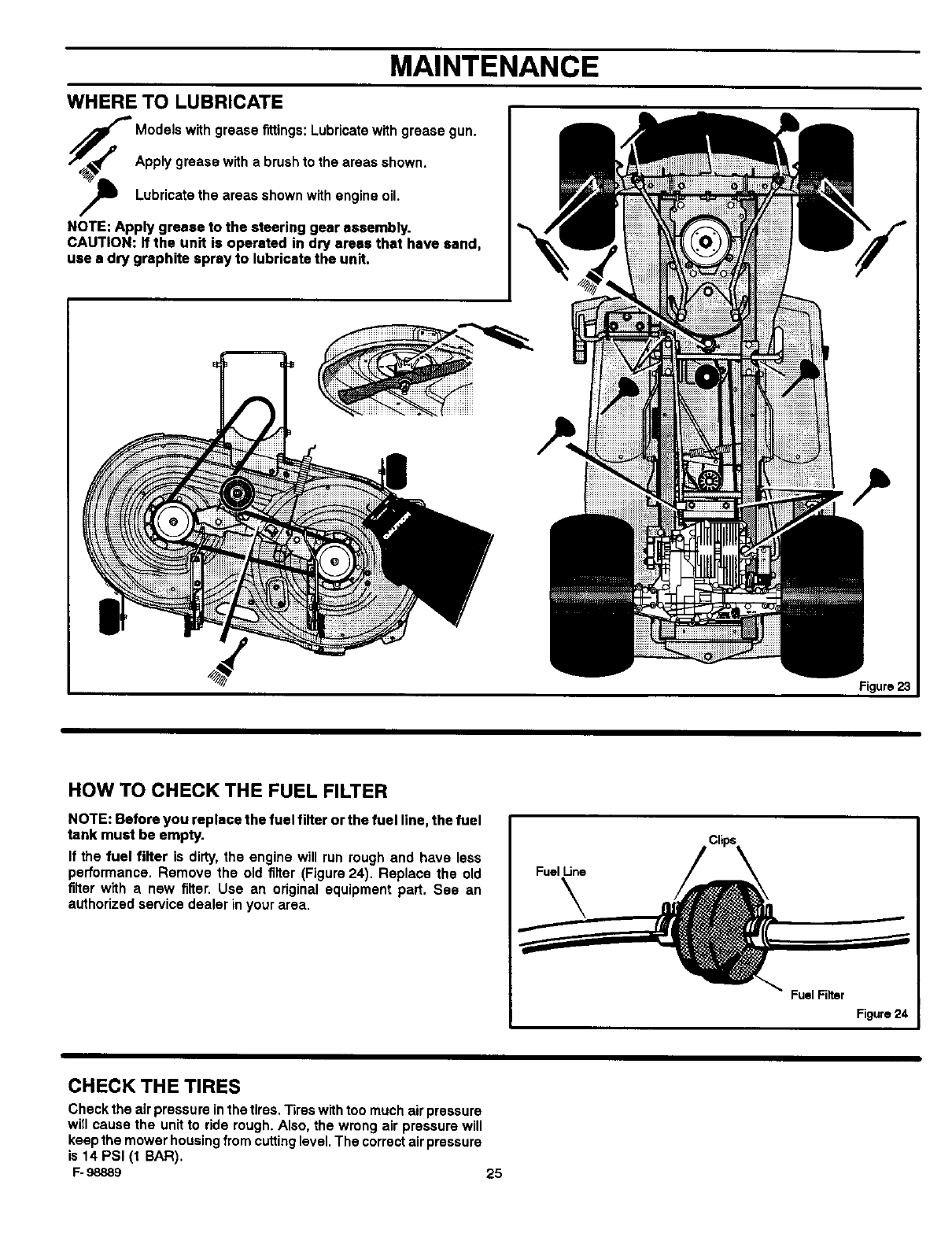
MAINTENANCE
WHERE TO LUBRICATE
_odels with grease fittings: Lubricate with grease gun.
Apply grease with a brush to the areas shown.
Lubricate the areas shown with engine oil.
NOTE: Apply grease to the steering gear assembly.
CAUTION: If the unit is operated in dry areas that have sand,
use • dry graphite spray to lubricate the unit.
Figure23
HOW TO CHECK THE FUEL FILTER
NOTE: Before you replace the fuel filter or the fuel line, the fuel
tank must be empty,
If the fuel filter is dirty, the engine will run rough and have less
performance. Remove the old filter (Figure 24). Replace the old
filter with a new filter. Use an original equipment part. See an
authorized service dealer in your area,
FuelLine
\
Fuel Filter
Figure 24
CHECK THE TIRES
Check the air pressure in the tires. "13reswith too much air pressure
win cause the unit to ride rough. Also, the wrong air pressure will
keep the mower housing from cutting level. The correct air pressure
is 14 PSI (t BAR).
F- 98889 25
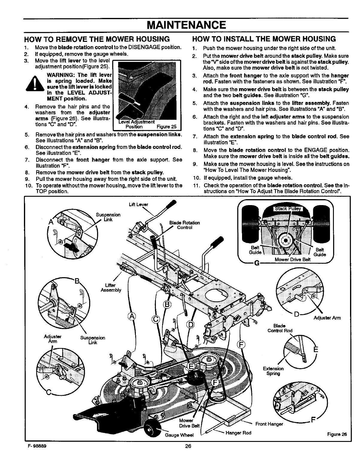
MAINTENANCE
HOW TO REMOVE THE MOWER HOUSING
1. Move the blade rotation control tothe DISENGAGE position.
2. If equipped, remove the gauge wheels.
3. Move the lift lever to the level
adjustment position(Figure 25).
WARNING: The lift lever
4_ia spring loaded. Makesurethe lift lever is locked
in the LEVEL ADJUST-
MENT position.
4. Remove the hair pins and the
washers from the adjuster
arms (Figure 26). See illustra-
tions =C" and _D'. us_nent Figure 25
5. Remove the hair pins and washers from the suspension links.
See illustrations =A" and =B".
6. Disconnect the extension spring from the blade control rod.
See illustration=E".
7. Disconnect the front hanger from the axle support. Sea
illustration=F".
8. Remove the mower drive belt from the stack pulley.
9. Pull the mower housing away from the right side of the unit.
10. To operate without the mower housing, move the littlever to the
TOP position.
HOW TO INSTALL THE MOWER HOUSING
1. Push the mower housing under the right side of the unit.
2. Put the mower drive belt around the stack pulley. Make sure
the _side ofth e mower drive belt is against the eta ek pulley.
Also, make sure the mower drive belt is not twisted.
3, Attach the front hanger to the axle support with the hanger
rod. Fasten with the fasteners as shown. See illustration=F".
4. Make sure the mower drive belt isbetween the stack pulley
and the two belt guides. See illustration"G'.
5. Attach the suspension links to the lifter assembly. Fasten
with the washers and hair pins. See illustrations"A" and =B'.
6. Attach the right and the left adjuster arms to the suspension
brackets. Fasten with the washers and hair pins. See illustra-
tions =C" and =D".
7. Attach the extension spring to the blade control rod. See
illustration=E'.
8. Move the blade rotation control to the ENGAGE position,
Make sure the mower drive belt is inside allthe belt guides.
9. Make sure the mower housing is level See the instructionson
=How To Level The Mower Housing'.
10. If equipped, install the gauge wheels.
11. Check the operation of the blade rotation control. See the In-
structions on "How To Adjust The Blade Rotation Control".
Lift Lever
Blade Rotation
Con_'ol
G, Mower Drive Belt
Lifter
Assembly
A_ster Suspension
Link
Adjuster Arm
Blade
Con_olRod
Extension_
Spnng
F- 98889
Mowof"
DriveBelt
GaugeWheel
26
Hanger Rod
Front Hanger
Figuro26
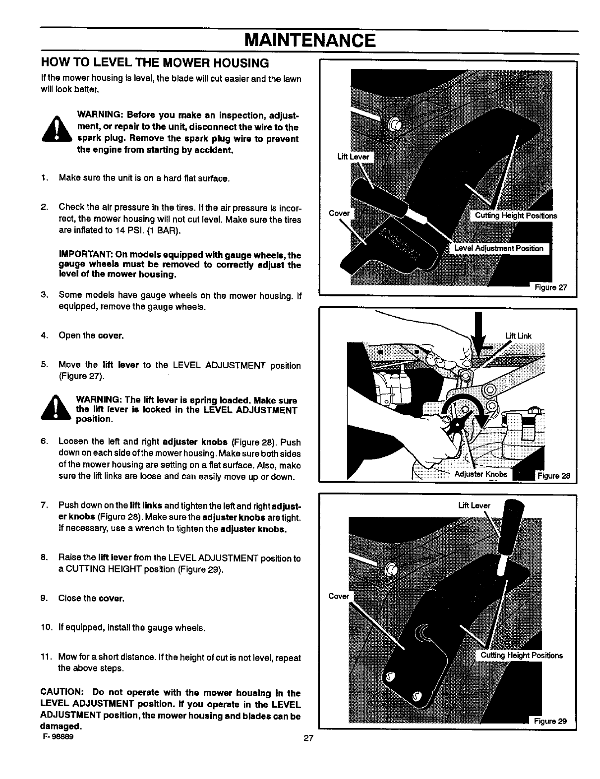
MAINTENANCE
HOW TO LEVEL THE MOWER HOUSING
Ifthe mower housing is level, the blade will cut easier and the lawn
will look better,
WARNING: Before you make an inspection, adjust-
Amant, or repair to the unit, disconnect the wire to the
spark plug. Remove the spark plug wire to prevent
the engine from starting by accident.
1, Make sure the unit is on a hard fiat surface.
2,
3,
Check the air pressure in the tires. If the air pressure is incor-
rect, the mower housing will not cut level. Make sure the tires
are inflated to 14 PSI. (1 BAR).
IMPORTANT: On models equipped with gauge wheels, the
gauge wheels must be removed to correctly adjust the
level of the mower housing.
Some models have gauge wheels on the mower housing. If
equipped, remove the gauge wheels.
LiftLever
Cutting Height Positions
Figure 27
4. Open the coven
5. Move the lift lever to the LEVEL ADJUSTMENT position
(Figure 27).
_lb WARNING: The lift lever is spring loaded. Make sure
the lift lever is locked in the LEVEL ADJUSTMENT
position.
6. Loosen the left and right adjuster knobs (Figure 28). Push
down on each side ofthe mower housing. Make sure both sides
of the mower housing are setting on a fiat surface. Also, make
sure the liftlinks are loose and can easily move up or down. Adjuster
LiftUnk
7. Push down on the lift links and tighten the leftand rightadjust-
er knobs (Figure 28), Make sure the adjuster knobs are tight.
if necessary, use a wrench to tighten the adjuster knobs.
8. Raise the lift lever from the LEVEL ADJUSTMENT position to
a CUTTING HEIGHT position (Figure 29).
9. Close the cover.
10. If equipped, installthe gauge wheels.
11. Mow for a short distance. Ifthe height of cut is not level, repeat
the above steps.
CAUTION: Do not operate with the mower housing in the
LEVEL ADJUSTMENT position. If you operate in the LEVEL
ADJUSTMENT position, the mower housing and blades can be
damaged.
F- 98889 27
LiftLever
Cutting Height Positions
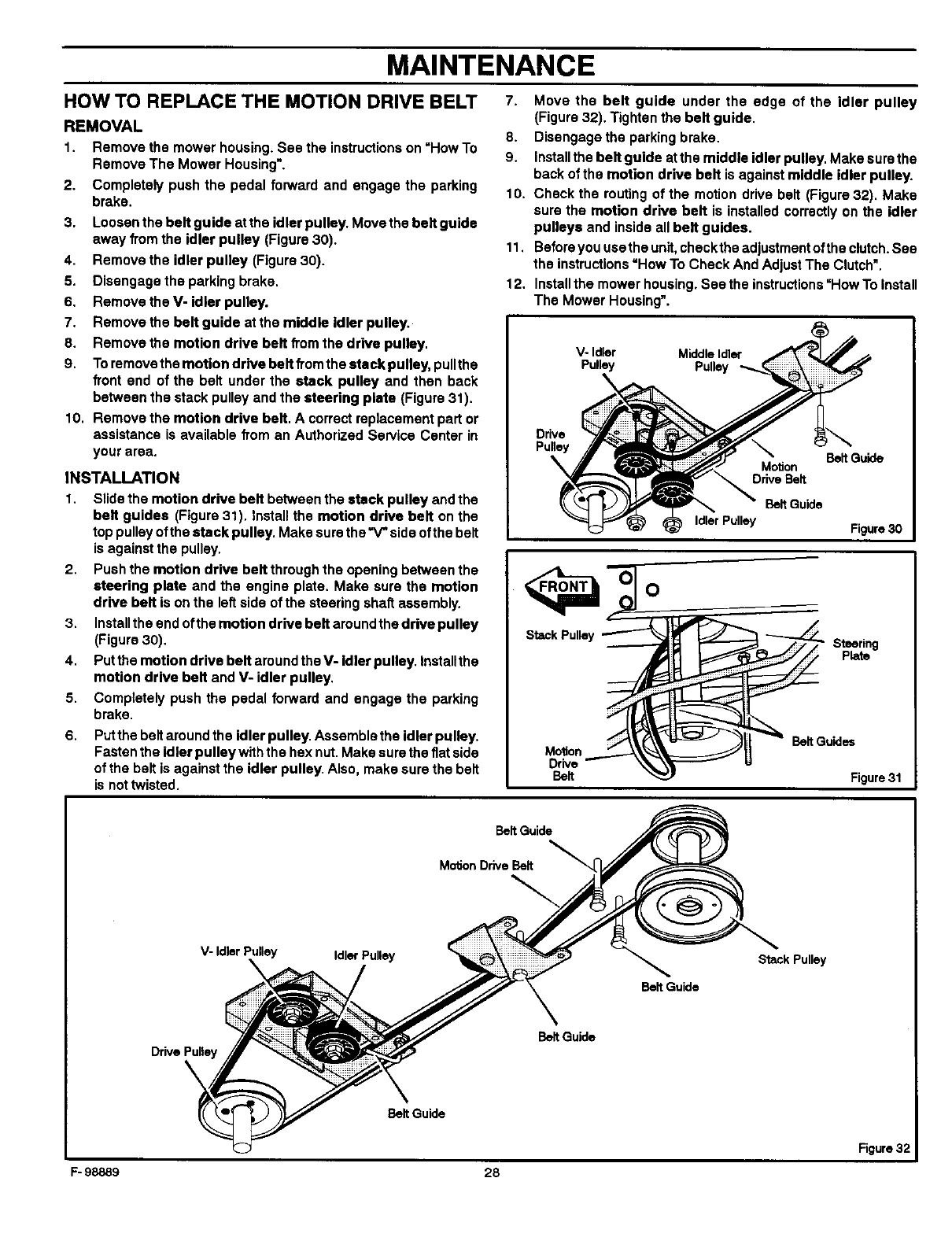
MAINTENANCE
HOW TO REPLACE THE MOTION DRIVE BELT 7.
REMOVAL 8.
1. Remove the mower housing. See the instructionson =How To
Remove The Mower Housing'. 9.
2. Completely push the pedal forward and engage the parking 10.
brake.
3. Loosen the belt guide at the idler pulley. Move the belt guide
away from the idler pulley (Figure 30).
4. Remove the idler pulley (Figure 30).
5. Disengage the parking brake.
6. Remove the V- idler pulley.
7. Remove the belt guide at the middle idler pulley.
8. Remove the motion drive belt from the drive pulley.
9. Toremove the motion drive belt from the stack pulley, pullthe
front end of the belt under the stack pulley and then back
between the stack pulley and the steering plate (Figure 31).
10. Remove the motion drive belt. A correct replecement part or
assistance is available from an Authorized Service Center in
your area.
INSTALLATION
1. Slide the motion drive belt between the stack pulley and the
belt guides (Figure 31). install the motion drive belt on the
top pulley ofthe stack pulley. Make sure the"V" side ofthe belt
is against the pulley.
2. Push the motion drive belt through the opening between the
steering plate and the engine plate. Make sure the motion
drive belt is on the left side of the steering shaft assembly.
3. Installthe end ofthe motion drive belt around the drive pulley
(Figure 30).
4, Put the motion drive belt around the V- idler pulley. Installthe
motion drive belt and V- idler pulley.
5. Completely push the pedal forward and engage the parking
brake.
6, Putthe belt around the idler pulley. Assemble the idler pulley.
Fasten the idler pulley withthe hex nut. Make sure the fiat side
of the belt is against the idler pulley. Also, make sure the belt
is not twisted.
11,
12,
Move the belt guide under the edge of the idler pulley
(Figure 32). Tighten the belt guide.
Disengage the parking brake.
Installthe belt guide atthe middle idler pulley. Make sure the
back of the motion drive belt is against middle idler pulley.
Check the routing of the motion drive belt (Figure 32). Make
sure the motion drive belt is installed correctly on the idler
pulleys and inside all belt guides.
Before you usethe unit, check the adjustment ofthe clutch. See
the instructions=How To Check And Adjust The Clutch".
Install the mower housing. See the instructions"How To install
The Mower Housing'.
Vo Idler Middle Idler
Pulley Pulley
Drive
Pulley
Molion
Drive Belt
Belt Guide
Idler Pulley Figure 30
BeltGuide_
Figure 31
Steering
Plate
Belt Guide
Motion Drive Belt
V- IdlerPulley
\Idler Pulley Stack Pulley
Drive Pulley
Belt Guide
Figure 3;
F- 98889 28
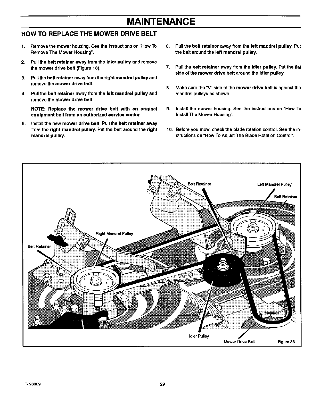
MAINTENANCE
HOW TO REPLACE THE MOWER DRIVE BELT
1.
2.
3,
4.
5_
Remove the mower housing. See the instructions on =How To
Remove The Mower Housing'.
Pull the belt retainer away from the idler pulley and remove
the mower drive belt (Figure 18).
Pull the belt retainer away from the right mandrel pulley and
remove the mower drive belt.
Pull the belt retainer away from the left mandrel pulley and
remove the mower drive belt.
NOTE: Replace the mower drive belt with en original
equipment belt from an authorized service center.
Install the new mower drive belt, Pull the belt retainer away
from the right mandrel pulley, Put the belt around the right
mandrel pulley.
6. Pull the belt retainer away from the left mandrel pulley. Put
the belt around the left mandrel pulley.
7. Pull the belt retainer away from the idler pulley. Put the flat
side of the mower drive belt around the idler pulley.
8. Make sure the _side of the mower drive belt is against the
mandrel pulleys as shown.
9. Install the mower housing. See the instructions on "How To
Install The Mower Housing".
10. Beforeyou mow,checkthe blade rotationcontrol.See the in-
structionson =HowToAdjustThe BladeRotationControl'.
Belt Retainer Left Mandrel Pulley
Belt Retainer
Belt Retainer
Idler Pulley
Mower Drive Belt Figure 33
F- 98889 29
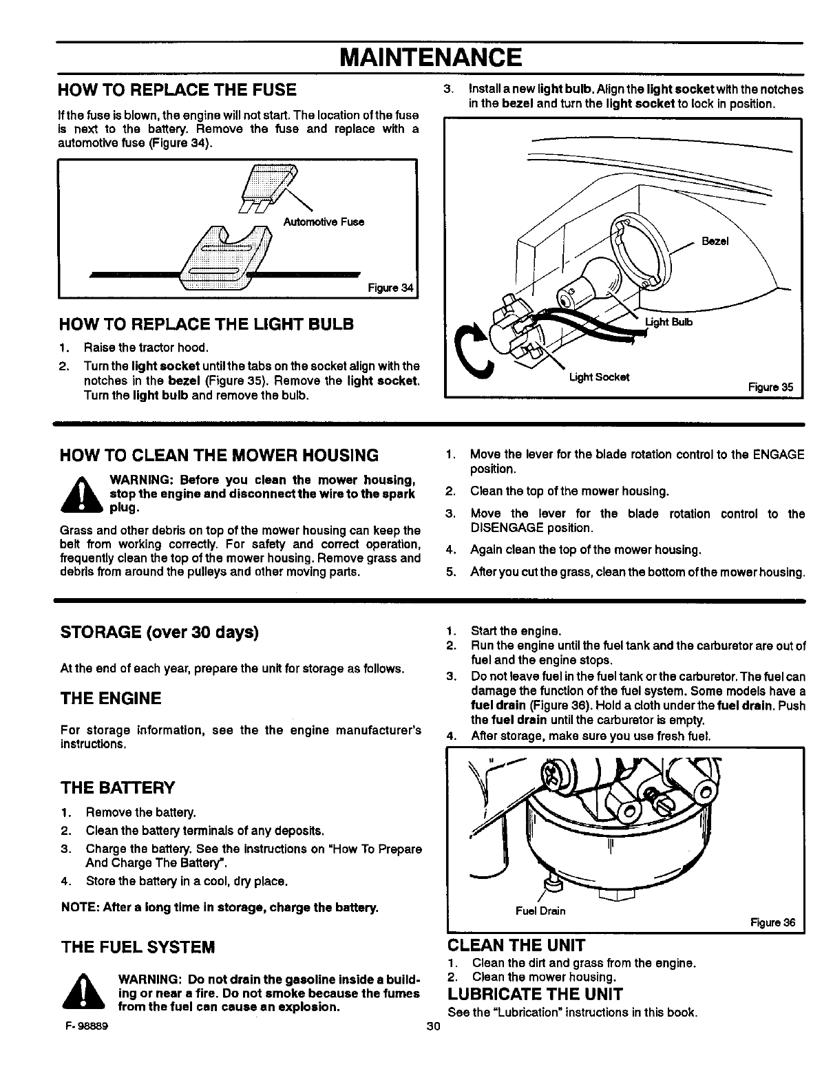
MAINTENANCE
HOW TO REPLACE THE FUSE
Ifthe fuse is blown, the engine will not start. The location of the fuse
is next to the battery. Remove the fuse and replace with a
automotive fuse (Figure 34).
Automotive Fuse
Figure 34
HOW TO REPLACE THE LIGHT BULB
1.
2.
Raise the tractor hood.
Turn the light socket untilthe tabs on the socket align withthe
notches in the bezel (Figure 35). Remove the light socket.
Turn the light bulb and remove the bulb.
3. Install a new light bulb. Alignthe light socket with the notches
in the bezel and turn the light socket to lock in position.
Light Socket Figure 35
HOW TO CLEAN THE MOWER HOUSING
A WARNING: Before you clean the mower housing,
stop the engine and disconnect the wire to the spark
plug.
Grass and other debris on top of the mower housing can keep the
belt from working correctly. For safety and correct operation,
frequently clean the top of the mower housing. Remove grass and
debris from around the pulleys and other moving parts.
1. Move the lever for the blade rotation control to the ENGAGE
position.
2. Clean the top of the mower housing.
3. Move the lever for the blade rotation control to the
DISENGAGE position.
4. Again clean the top of the mower housing.
5. After you cut the grass, clean the bottom oftha mower housing.
STORAGE (over 30 days)
At the end of each year, prepare the unit for storage as follows.
THE ENGINE
For storage information, see the the engine manufacturer's
instructions.
THE BATTERY
1. Remove the battery.
2. Clean the battery terminals of any deposits.
3. Charge the battery. Sea the instructions on =How To Prepare
And Charge The Battery'.
4. Store the battery in a cool, dry place.
NOTE: After a long time in storage, charge the battery.
THE FUEL SYSTEM
A
F- 98889
WARNING: Do not drain the gasoline inside a build-
ing or near a fire. Do not smoke because the fumes
from the fuel can cause an explosion.
3O
1. Start the engine.
2. Run the engine untilthe fuel tank and the carburetor are out of
fuel and the engine stops.
3. Do not leave fuel inthe fuel tank or the carburetor. The fuel can
damage the function of the fuel system. Some models have a
fuel drain (Figure 36). Hold a cloth under the fuel drain. Push
the fuel drain until the carburetor is empty.
4. After storage, make sure you use fresh fuel
Fuel Drain
CLEAN THE UNIT
1. Clean the dirt and grass from the engine.
2. Clean the mower housing.
LUBRICATE THE UNIT
See the =Lubrication" instructions inthis book.
Figure 36
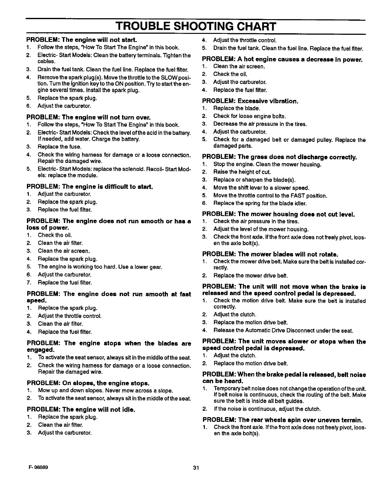
TROUBLE SHOOTING CHART
PROBLEM: The engine will not start.
1. Follow the steps, =How To Start The Engine" in this book.
2. Electric- Start Models: Clean the battery terminals. Tighten the
cables.
3. Drain the fuel tank. Clean the fuel line. Replace the fuel filter.
4. Remove the spark plug(s). Move the throttle to the SLOW posi-
tion. Turn the ignition key to the ON position. Try to start the en-
gine several times. Install the spark plug.
5. Replacethe sparkplug.
6. Adjust the carburetor.
PROBLEM: The engine will not turn over.
1. Follow the steps, =How To Start The Engine" in this book.
2. Electric- Start Models: Checkthe level ofthe acid inthe battery.
If needed, add water. Charge the battery.
3. Replace the fuse.
4. Check the wiflng harness for damage or a loose connection.
Repair the damaged wire.
5. Electric- Start Models: replace the solenoid. Recoil- Start Mod-
els: replace the module.
PROBLEM: The engine is difficult to start.
1. Adjust the carburetor.
2. Replace the spark plug.
3. Replace the fuel filter.
PROBLEM: The engine does not run smooth or has s
loss of power.
1. Check the oil.
2. Clean the air filter.
3. Clean the air screen.
4. Replace the spark plug.
5. The engine is working too hard. Use a lower gear.
6. Adjust the carburetor.
7. Replace the fuel filter.
PROBLEM: The engine does not run smooth st fast
speed.
1. Replacethe sparkplug.
2. Adjustthe throttlecontrol.
3. Clean the airfilter.
4. Replacethe fuelfilter.
PROBLEM: The engine stops when the blades are
engaged.
1. Toactivatethe seatsensor,always sitinthe middleoftheseat.
2. Checkthe wiringharnessfor damageor a looseconnection.
Repairthe damagedwire.
PROBLEM: On slopes, the engine stops.
1. Mow up and down slopes. Never mow across a slope.
2. To activate the seat sensor, always sit inthe middle of the seat.
PROBLEM: The engine will not idle.
1. Replace the spark plug.
2. Clean the air filter.
3. Adjust the carburetor.
4. Adjust the throttle control.
5. Drain the fuel tank. Clean the fuel line. Replace the fuel filter.
PROBLEM: A hot engine causes a decrease in power.
1. Clean the air screen.
2. Check the oil.
3. Adjust the carburetor.
4. Replace the fuel filter.
PROBLEM: Excessive vibration.
1. Replace the blade.
2. Check for loose engine bolts.
3. Decrease the air pressure in the tires.
4. Adjust the carburetor.
5. Check for a damaged belt or damaged pulley. Replace the
damaged parts.
PROBLEM: The grass does not discharge correctly.
1. Stop the engine. Clean the mower housing.
2. Raise the height of cut.
3. Replace or sharpen the blade(s).
4. Move the shift lever to a slower speed.
5. Move the throttle control to the FAST position.
6. Replace the spring for the blade idler.
PROBLEM: The mower housing does not cut level.
1. Check the air pressure in the tires.
2. Adjust the level of the mower housing.
3. Check the front axle. Ifthe front axle does not freely pivot, loos-
en the axle bolt(s).
PROBLEM: The mower blades will not rotate.
1. Check the mower drive belt. Make sure the belt isinstalled cor-
rectly.
2. Replace the mower drive belt.
PROBLEM: The unit will not move when the brake is
released and the speed control pedal Is depressed.
1. Check the motion drive belt. Make sure the belt is installed
correctly.
2. Adjust the clutch.
3. Replace the motion drive belt.
4. Release the Automatic Drive Disconnect under the seat.
PROBLEM: The unit moves slower or stops when the
speed control pedal is depressed.
1. Adjustthe clutch.
2. Replacethe motion drivebelt.
PROBLEM: When the brake pedal is released, belt noise
can be heard.
1. Temporary belt noise does not changethe operation ofthe unit.
If belt noise is continuous, check the routing of the belt. Make
sure the belt isinside all belt guides.
2. If the noise is continuous, adjust the clutch.
PROBLEM: The rear wheels spin over uneven terrain.
1. Check the front axle. Ifthe front axle does not freely pivot, loos-
en the axle bolt(s).
F.98889 31
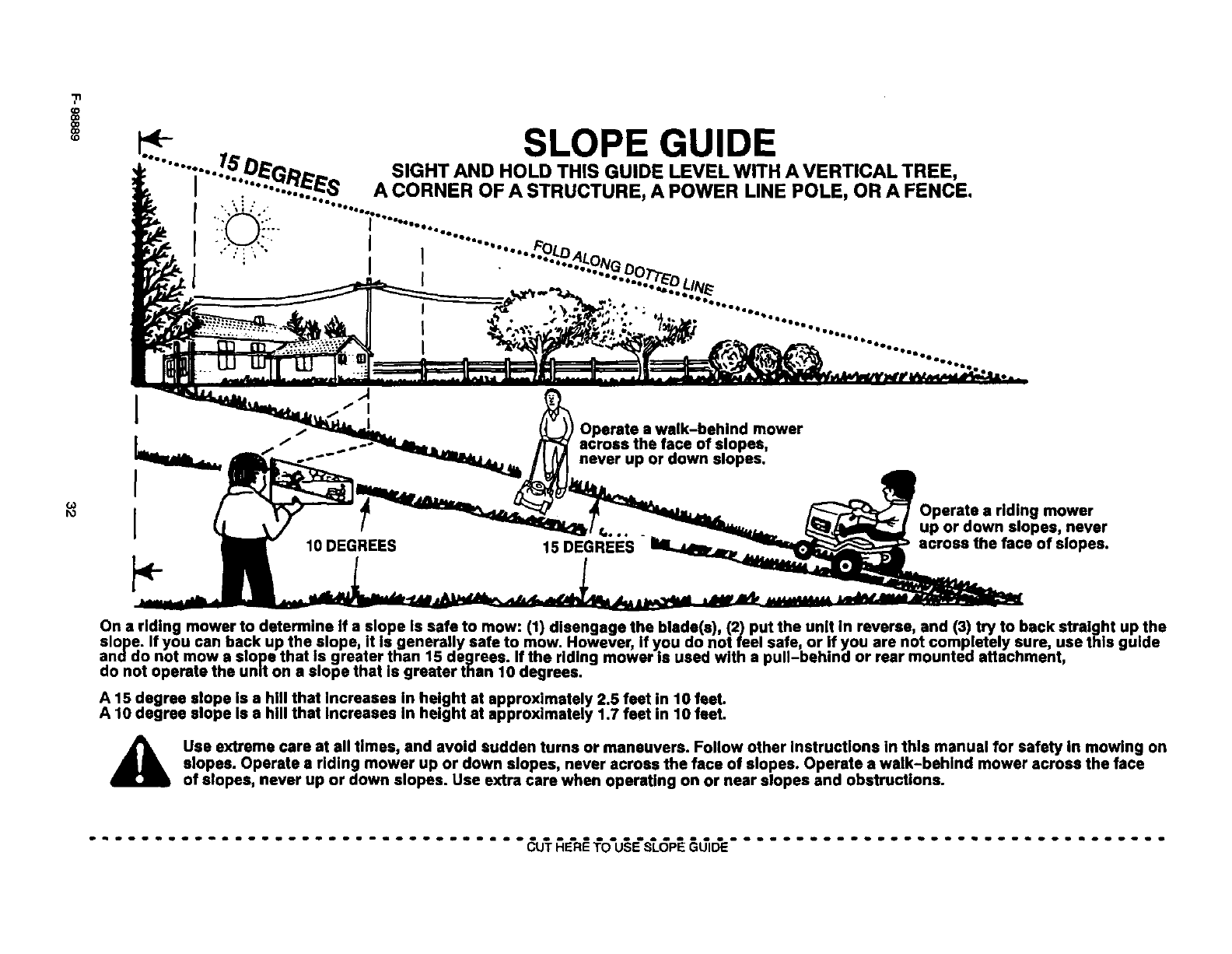
(D
co
D_
Operate a walk-behind mower
across the face of slopes,
never up or down slopes.
I10 DEGREES 15 DEGREES
mower
up or down slopes, never
across the face of slopes.
On a riding mower to determine If a slope Is safe to mow: (1) disengage the blade(s) (2) put the unit in reverse, and (3) try to back straight up the
slope. If you can back up the slope, It Is generally safe to mow. However, if you do not feel safe, or if you are not completely sure, use this guide
anddo not mow e slope that Is greater than 15 degrees. If the riding mower Is used with a pull-behind or rear mounted attachment,
do not operate the unit on a slope that is greater than 10 degrees.
A 15 degree slope Is a hill that Increases In height at approximately 2.5 feet in 10 feet.
A 10 degree slope Is a hill that Increases In height at approximately 1.7 feet in 10 feet.
A se extreme care at all times, and avoid sudden turns or maneuvers. Follow other Instructions in this manual for safety In mowing on
slopes. Operate a riding mower up or down slopes, never across the face of slopes. Operate a walk-behind mower across the face
of slopes, never up or down slopes. Use extra care when operating on or near slopes and obstructions.
................................. I'O'U§E'S'L P .................................

NOTES
F- 98889 33

NOTES
F- 98889 34

INDEX
Throttle Control, 13
A
Adjustments
Blade Rotation Control, 22
Clutch, 23
Drive Brake, 23
Mower Housing, Level, 27
Speed Control Pedal, 24
Attachments, 13, 36
Automatic Drive Disconnect,
Operation, 14
B
Battery
Charge, 24
Check, 11
Clean, 24
install, 11
Removal, 24
Storage, 30
Belt
Motion Drive
Adjust, 23
Replace, 28
Mower Drive
Adjust, 22
Replace, 29
Blade
Inspect, 21
Remove And Instalt, 21
Sharpen, 21
Blade Rotation Control
Adjust, 22
Location, 12
Operation, 13
Brake Pedal, Location, 12
C
Clutch
Adjust, 23
Check, 23
Controls, Location, 12
Cutting Height
Adjust, 27
Change, 15
D
Drive Brake
Adjust, 23
Check, 23
E
Engine
Fuel, 11, 17
Oil, 11,17
Preparation, 11
Spark Arroster, 11, 20
Starting, 17
Storage, 30
F- 98889
F
Filter, Fuel, 25
Fuel, Type, 17
Fuse, 30
H
Headlight, Replace Light Bulb, 30
Headlight Switch, Location, 12
I
Ignition Switch, Location, 12
L
Lift Lever
Location, 12
Operation, 15
Lubrication, Mower, 25
M
Maintenance
Battery
Charge, 24
Clean, 24
Belt
Motion Drive, 28
Mower Drive, 29
Blade, 21
Blade Rotation Control, 22
Clutch, 23
Drive Brake, 23
Filter, Fuel, 25
Fuse, 30
Headlight, 30
Lubrication, 25
Mower Housing
Clean, 30
Install, 26
Level, 27
Remove, 26
Muffler, 20
Speed Control Pedal, 24
Storage, 30
Maintenance Chart, 20
Motion Drive Belt
Adjust, 23
Replace, 28
Mower Drive Belt
Adjust, 22
Replace, 29
Mower Housing
Clean, 30
Cutting Height, 15
Install, 26
Level Adjustment, 27
Operation, 16
Remove, 26 35
Muffler, 20
Spark Arrester, 20
Mulcher
Install, 19
Remove, 19
O
Oil
Check, 17
Type, 17
Operation
Attachments, 13
Automatic Drive Disconnect, 14
Blade Rotation Control, 12, 13
Brake Pedal, 12
Headlight Switch, 12
Ignition Switch, 12
Lift Lever, 12, 15
Location Of Controls, 12
Mower Housing, 16
Mowing And Bagging, 18
Operate On Hills, 16
Parking Brake, 12, 15
Speed Control Pedal, 12, 14
Start The Engine, 17
Stop The Unit, 15
Throttle Control, 12, 13
Transport, 15
P
Parking Brake
Location, 12
Operation, 15
Parts Bag, 9
S
Safety Rules
AmericanNationalStandardInstitute,3-4
Safe Mowing Guide, 5-7
Seat, Install, 10
Seat Switch, Operation, 17
Slope Guide, 32
Spark Arrester, 11, 20
Speed Control Pedal
Adjust, 24
Location, 12
Operation, 14
Steering Wheel, 10
Storage, 30
T
Throttle Control
Location, 12
Operation, 13
Tire Pressure, 9, 25
Trouble Shooting Chart, 31
W
Warranty, 2
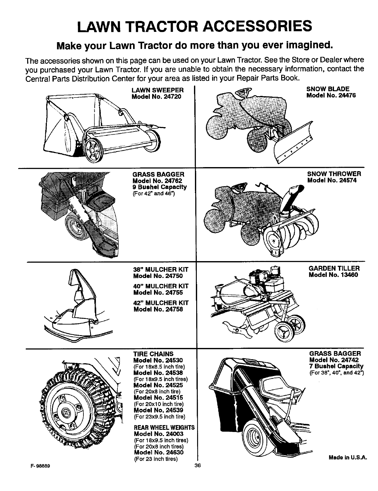
LAWN TRACTOR ACCESSORIES
Make your Lawn Tractor do more than you ever imagined.
The accessories shown on this page can be used on your Lawn Tractor. See the Store or Dealer where
you purchased your Lawn Tractor. If you are unable to obtain the necessary information, contact the
Central Parts Distribution Center for your area as listed in your Repair Parts Book.
LAWN SWEEPER
Model No. 24720
GRASS BAGGER
Model No. 24762
9 Bushel Capacity
(For 42" and 46")
38" MULCHER KIT
Model No. 24750
40" MULCHER KIT
Model No. 24755
42" MULCHER KIT
Model No. 24758
F- 98889
TIRE CHAINS
Model No, 24530
(For 18x8.5 inchtire)
Model No. 24538
(For18x9.5 inchtires)
Model No. 24525
(For20:<8inchtire)
Model No. 24515
(For20xl 0 inchtire)
Model No. 24539
(For23x9.5 inchtire)
REAR WHEEL WEIGHTS
Model No. 24003
(For 18x9.5 inch tires)
(For 20x8 inch tires)
Model No. 24630
(For 23 inch tires) 36
SNOW BLADE
Model No. 24476
SNOW THROWER
Model No. 24574
GARDEN TILLER
Model No. 13460
GRASS BAGGER
Model No. 24742
7 Bushel Capacity
(For 38", 40", and 42")
Made in U.S.A.
