Music Tribe Commercial MY Sdn Bhd PPA2000BT Portable PA System User Manual PPA2000BT Manual 2013 12 9
MUSIC Group Services PH Corp Portable PA System PPA2000BT Manual 2013 12 9
UserManual.wiki
>
Music Tribe Commercial MY Sdn Bhd
>
PPA2000BT User Manual
QWHPPA2000BT_users Manual_rev.1
Navigation menu
Upload a User Manual
Namespaces
Wiki Guide
HTML
PDF
Info
Views
User Manual
Discussion / Help
Navigation

![PAN knob positions each channel in the stereo field. LEVEL knob adjusts the volume of the individual channel in the overall mix. CLIP LED lights when the input signals overloads the channel. PROGRAM[PUSH] knob controls the effects settings. Rotate this knob to scroll through the effect patches, and push to select a patch. MULTI-FX PROCESSOR unit adds a selected sound effect to any channels which have their EFFECTS knob turned up. Effects include reverb, chorus, delay, and pitch shifter. FX[LEVEL] knob controls the amount of effects added to the main mix.](https://usermanual.wiki/Music-Tribe-Commercial-MY-Sdn-Bhd/PPA2000BT/User-Guide-2142723-Page-10.png)
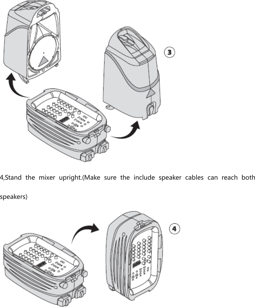
![Step 5: Adding Effects 1,Set the FX [LEVEL] knob on the DIGITAL EFFECTS PROCESSOR to approximately a 75% setting. 2, Scroll through the available effects by turning the PROGRAM [PUSH] knob. The number in the display will flash. 3, Press the PROGRAM [PUSH] knob to select the effect. The number will stop flashing. 4, While speaking, singing, or playing, turn the channel FX knob up to the desired level on each channel to which you wish to add effects.](https://usermanual.wiki/Music-Tribe-Commercial-MY-Sdn-Bhd/PPA2000BT/User-Guide-2142723-Page-19.png)
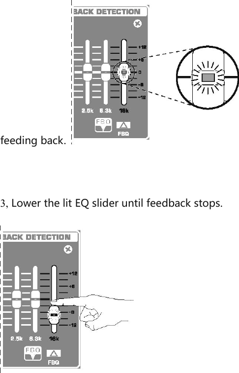
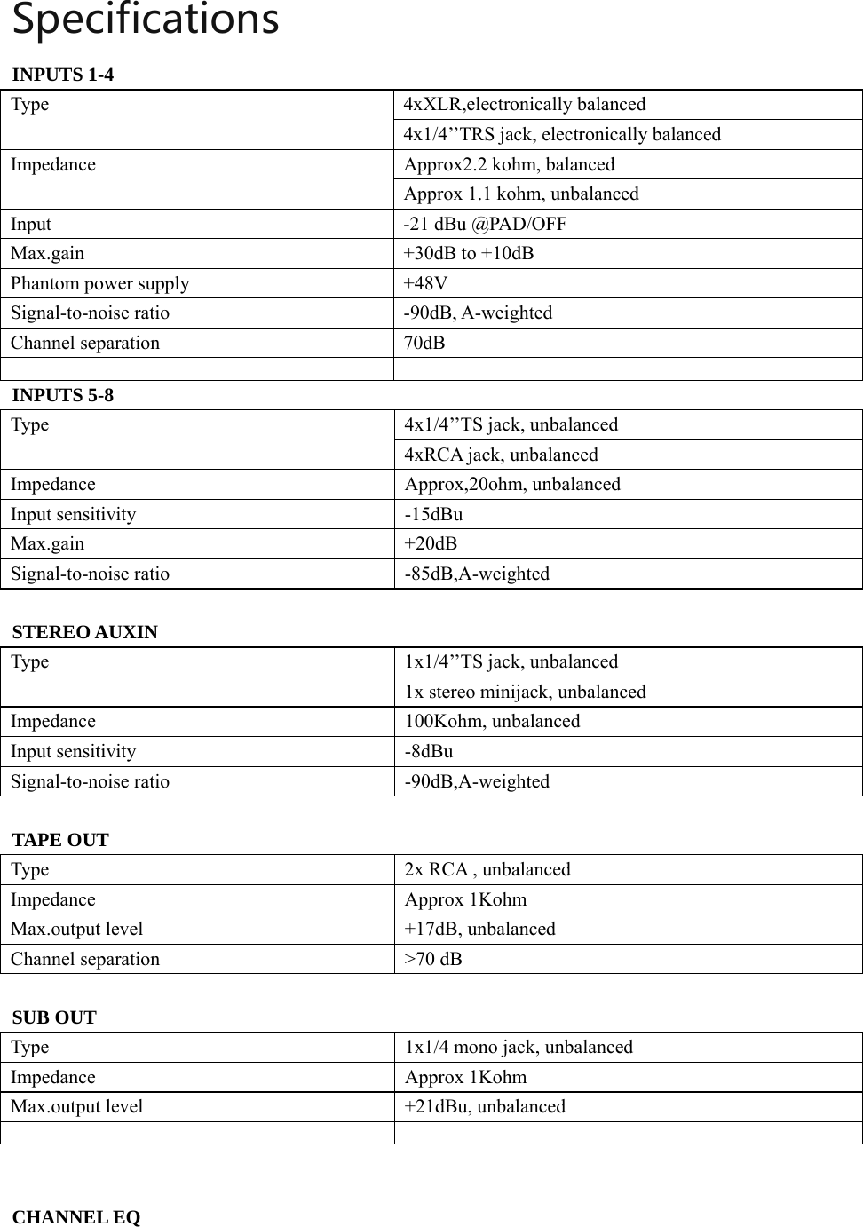
![5, Adjust the FX [LEVEL] knob on the DIGITAL EFFECTS PROCESSOR up or down from the initial 75% setting to achieve your desired overall effects level in the main mix. Step 6: Feedback Detection “Feedback” is the undesirable high-pitched sound created by sound waves looping between the speakers and the microphones. 1, If feedback occurs, press the EQ and FBQ ON buttons. 2, An LED will light on the EQ slider that corresponds with the specific sound frequency](https://usermanual.wiki/Music-Tribe-Commercial-MY-Sdn-Bhd/PPA2000BT/User-Guide-2142723-Page-20.png)