MyBinding Baum Flexifold Manual User
2013-06-04
User Manual: MyBinding Baum-Flexifold-Manual
Open the PDF directly: View PDF ![]() .
.
Page Count: 31

FLEXIFOLD
8 PAGE
INSTALLATION, OPERATION,
&
PARTS MANUAL
©Baumfolder Corp., 2003 Printed in U.S.A TP10432
BAUM

TP10432 PAGE 2
WARNING
• Do not operate this machine without all guarding in place.
• Do not make adjustments or perform maintenance on this machine with power on.
• Keep the machine and the work area clean and free of spills to prevent accidents.
• Be sure to replace any safety decals that may have been detached for any reason.
BAUMFOLDER reserves the right to make changes in design or to make additions or improvements
in its products without imposing any obligation upon itself to install them on its products previously
manufactured. It is recommended that modifications to this equipment not be made without the advice
and express written consent of BAUMFOLDER.
FOLDER IDENTIFICATION
MODEL NO: _______________________________ SERIAL NO: _____________________________
DEALER : __________________________________________________________________________
INSTALLED BY: _____________________________________________ DATE: ________________
PHONE NO: _______________________________
© 2003 Baumfolder Corporation
All Rights Reserved

PAGE 3 TP10432
TABLE OF CONTENTS
FUNDAMENTAL SAFETY INSTRUCTIONS ............................................................................... 5
1.0 INTRODUCTION ....................................................................................................................... 9
2.0 SPECIFICATIONS ..................................................................................................................... 9
3.0 INSTALLATION ......................................................................................................................... 9
3.1 Unpacking & Inspection ................................................................................................................ 9
4.0 ASSEMBLY................................................................................................................................ 10
4.1 Main Unit ..................................................................................................................................... 10
4.2 Transfer Table .............................................................................................................................. 10
4.3 Delivery Table .............................................................................................................................. 10
4.4 Cross Carrier Assembly Installation ............................................................................................ 10
4.5 Fold Plate Installation .................................................................................................................. 10
5.0 ELECTRICAL ACCESS ..........................................................................................................11
6.0 OPERATION ............................................................................................................................. 11
6.1 The Main Power/Reset Switch .................................................................................................... 11
6.2 Starting the Production Job .......................................................................................................... 11
6.3 Check Squareness of Fold............................................................................................................ 11
6.4 Use Of Handwheel....................................................................................................................... 12
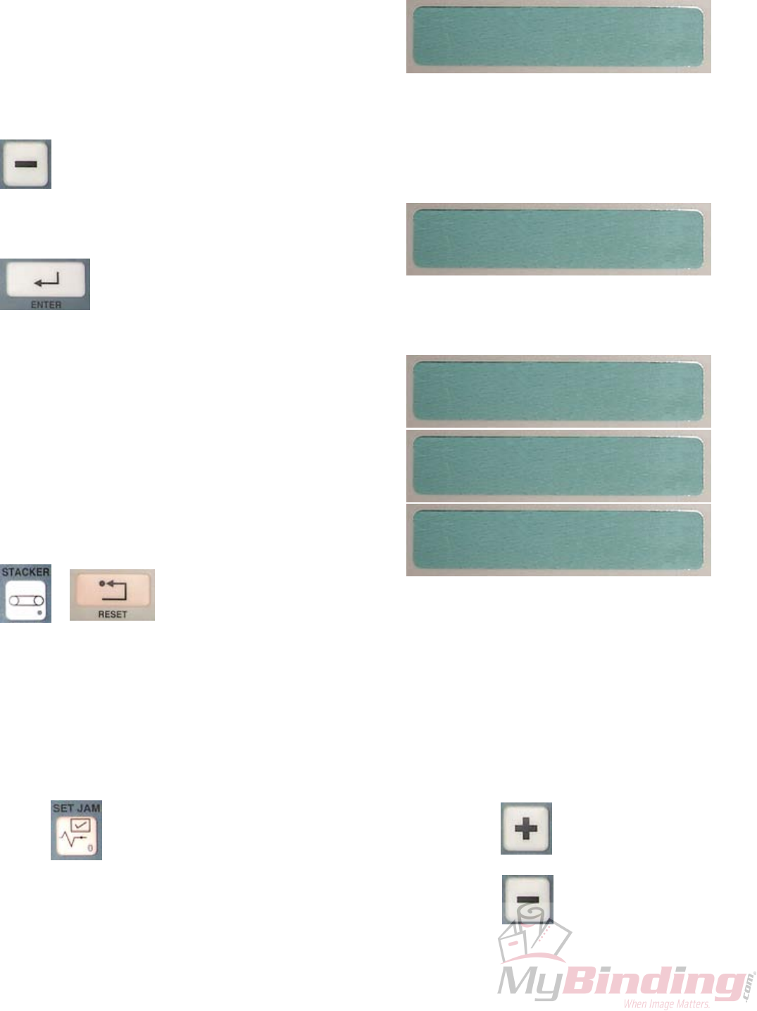
7.0 OPERATOR PANEL................................................................................................................. 12
7.1 Button Identification (2nd Function)........................................................................................... 12
8.0 START UP .................................................................................................................................. 13
9.0 SETUP ......................................................................................................................................... 13
9.1 Setup for a Standard Fold ............................................................................................................. 13
9.2 Setting Up a Special Fold ............................................................................................................. 15
9.2.1 To Save a Non-Standard Fold in a Memory Location ............................................................... 15
9.2.2 Recall a Fold Saved in Memory Location ................................................................................. 15
9.3 Starting the Production ................................................................................................................. 15

TP10432 PAGE 4
TABLE OF CONTENTS
10.0 COUNTER OPERATION ....................................................................................................... 16
10.1 Resetting the Total Count ........................................................................................................... 16
10.2 Rate ............................................................................................................................................. 16
11.0 FOLDER OPERATION ...........................................................................................................17
11.1 Time ............................................................................................................................................ 17
11.2 Start/Stop Button......................................................................................................................... 17
11.3 Speed........................................................................................................................................... 18
11.4 Fold Plates .................................................................................................................................. 18
11.5 Stacker Wheels ........................................................................................................................... 19
11.6 Paper Jams .................................................................................................................................. 20
11.7 Shutting Off Jam Detectors......................................................................................................... 20
12.0 PERFORATING, SCORING & SLITTING .......................................................................... 22
12.1 Perforating .................................................................................................................................. 22
12.2 Scoring........................................................................................................................................ 23
12.3 Slitting ........................................................................................................................................ 23
13.0 MAINTENANCE ..................................................................................................................... 24
13.1 Maintenance and Care of your Flexifold .................................................................................... 24
13.2 Cleaning of Fold Rolls................................................................................................................ 24
13.3 Cleaning Filters........................................................................................................................... 24
13.4 Photo Eyes .................................................................................................................................. 24
13.5 Cleaning The Fold Stop Guides.................................................................................................. 24
13.6 Replacement Parts ...................................................................................................................... 24
14.0 LANGUAGE SELECTION..................................................................................................... 25
15.0 DISPLAY MESSAGES ............................................................................................................ 26
16.0 MATERIAL SAFETY DATA SHEET .................................................................................... 27
17.0 BASIC THEORY OF BUCKLE FOLDING .......................................................................... 28
18.0 PARTS SECTION ........................................................................................................................

PAGE 5 TP10432
FUNDAMENTAL
SAFETY
INSTRUCTIONS!
The diagrams and descriptions used in these instructions are not necessarily
applicable to the specification of the machine supplied. Modifications, made
for reasons of technical or operational improvement, are embodied without
notice.

TP10432 PAGE 6
FUNDAMENTAL SAFETY
INSTRUCTIONS!
These operating instructions are designed to familiarize
the user with the machine and its designated use.
The instruction manual contains important information on
how to operate the machine safely, properly and most efficiently.
Observing these instructions helps to avoid danger, to reduce
repair costs and downtimes and to increase the reliability and life
of the machine.
In addition to the operating instructions and to the mandatory rules
and regulations for accident prevention and environmental
protection in the country and place of use of the machine, the
generally recognized technical rules for safe and proper working
must also be observed.
The following signs and designations are used in the
manual to designate instructions of particular importance.
Important
(refers to special information on how to use the
machine/plant most efficiently)
Attention
(refers to special information and/or orders and
prohibitions directed towards preventing
damage)
Danger
(refers to orders and prohibitions designed pre-
vent injury or extensive damage)
1.0
Basic operation and designated use of the machine/
plant
1.0.1
The machine has been built in accordance with
state-of-the art standards and the recognized safety rules.
Nevertheless, its use may constitute a risk to life and limb
of the user or of third parties, or cause damage to the
machine and to other material property.
1.0.2
The machine must only be used in technically perfect
condition in accordance with its designated use and the
instructions set out in the operating manual, and only by
safety-conscious persons who are fully aware of the risks
involved in operating the machine. Any functional
disorders, especially those affecting the safety of the
machine, should therefore be rectified immediately.
1.0.3
The machine/installation is designed exclusively for paper
finishing of minimum and maximum sheet sizes (see
corresponding operating instructions). Using the machine/
installation for purposes other than those mentioned above is
considered contrary to its designated use. The manufacturer/
supplier cannot be held liable for any damage or injury arising
from such misuse. The risk of such misuse lies entirely with the
user.
Operating the machine within the limits of its designated use also
involves observing the instructions set out in the operating manual
and complying with the inspection and maintenance directives.
The working temperature of the machine should range between 0°
and 55° C.
1.1 Organizational measures
1.1.1
The operating instructions must always be at hand at the place of
use of the machine, e.g. by stowing them in the tool compartment
or tool-box provided for such purpose.
1.1.2
Personnel entrusted with work on the machine must have read the
operating instructions and in particular the chapter on safety
before beginning work. Reading the instructions after work has
begun is too late. This applies especially to persons working only
occasionally on the machine, e.g. during setting up or
maintenance.
1.1.3
For reasons of security, long hair must be tied back or otherwise
secured, garments must be close-fitting and no jewelry - such as
rings - may be worn. Injury may result from being caught up in the
machinery or from rings catching on moving parts.
1.1.4
Observe all safety instructions and warnings attached to the
machine.
1.1.5
See to it that safety instructions and warnings attached to the
machine are always complete and perfectly legible.
1.1.6
In the event of safety-relevant modifications or changes in the
behaviour of the machine during operation, stop the machine
immediately and report the malfunction to the competent
authority/person.
1.1.7
Never make any modifications, additions or conversions which
might affect safety without the supplier’s approval. This also
applies to the installation and adjustment of safety devices and
valves as well as to welding work on load-bearing elements.
1.1.8
Spare parts must comply with the technical requirements specified
by the manufacturer. Spare parts from original equipment
manufacturers can be relied to do so.

PAGE 7 TP10432
1.1.9
Report any accident that occurs due to a malfunction of the machine
though all prescribed safety precautions were observed directly to
our agency or to the Baumfolderservice department.
1.2 Selection and qualification of personnel
- Basic responsibilities
1.2.1
Employ only trained or instructed staff and set out clearly the
individual responsibilities of the personnel for operation, set-up,
maintenance and repair.
1.2.2
Make sure that only authorized personnel works on or with the
machine.
1.2.3
Work on the electrical system and equipment of the machine must
be carried out only by a skilled electrician or by instructed persons
under the supervision and guidance of a skilled electrician and in
accordance with electrical engineering rules and regulations.
1.2.4
Work on gas fueled equipment (gas consumers) may be carried out
by specially trained personnel only.
1.3 Safety instructions governing specific
operational phases
1.3.1 Standard operation
1.3.1.1
Avoid any operational mode that might be prejudicial to safety.
1.3.1.2
Take the necessary precautions to ensure that the machine is used
only when in a safe and reliable state. Operate the machine only if
all protective and safety-oriented devices, such as removable safety
devices, emergency shut-off equipment, sound-proofing elements
and exhausters, are in place and fully functional.
1.3.1.3
Check the machine at least once per working shift for obvious
damage and defects. Report any changes (incl. changes in the
machine’s working behaviour) to the competent organization/person
immediately. If necessary, stop the machine immediately and lock it.
1.3.1.4
Before starting up or setting the machine in motion, make sure that
nobody is at risk.
1.3.2
Special work in conjunction with utilization of the machine and
maintenance and repairs during operation; disposal of parts and
consumables.
1.3.2.1
Always press the emergency (Not-Stop) button first, if you stop the
machine for adjustments or maintenance work which must not be
done while the machine is in operation.
1.3.2.2
For extensive maintenance or repair work, turn off the main power
supply.
1.3.2.3
After making adjustments or after doing maintenance or repair
work, always make sure that all tools or other objects are removed
from the machine. Otherwise they might fall into the machine,
causing severe damage or injuries.
1.3.2.4
Keep the floor around the entire machine clean. Immediately clean
any oil, grease or paint spills up off the floor. Remove tools,
cleaning cloths or paper scraps from all work areas.
1.3.2.5
Never operate a folding machine without buckle plates or deflectors
since these are protective as well.
1.3.2.6
Never clean moving parts of the machine (rollers, shafts) or remove
any test sheets, spoiled sheets or bits of paper in such areas.
1.3.2.7
Observe the adjusting, maintenance and inspection activities and
intervals set out in the operating instructions, including information
on the replacement of parts and equipment. These activities may be
executed by skilled personnel only.
1.3.2.8
Brief operating personnel before beginning special operations and
maintenance work, and appoint a person to supervise the activities.
1.3.2.9
If the machine is completely shut down for maintenance and repair
work, it must be secured against inadvertent starting by:
– locking the principal control elements and
removing the ignition key and/or
– attaching a warning sign to the main switch.
1.4.1 Electric energy
1.4.1.1
Use only original fuses with the specified current rating. Switch off
the machine/plant immediately if trouble occurs in the electrical
system.
1.4.1.2
If provided for in the regulations, the power supply to parts of
machines and plants, on which inspection, maintenance and repair
work is to be carried out must be cut off. Before starting any work,
check the de-energized parts for the presence of power and ground
or short-circuit them in addition to insulating adjacent live parts and
elements.

TP10432 PAGE 8
1.4.1.3
The electrical equipment of machines is to be inspected and checked
at regular intervals. Defects such as loose connections or scorched
cables must be rectified immediately.
1.4.1.4
Necessary work on live parts and elements must be carried out only
in the presence of a second person who can cut off the power supply
in case of danger by actuating the emergency shut-off or main power
switch. Secure the working area with a red-and-white safety chain
and a warning sign. Use insulated tools only.
1.4.1.5
Only unplug or plug electrical connectors if the main switch has
been disconnected.
1.4.1.6
Only connect the folding units and no machines of other brands to
the existing connectors. Any electrical connection of
BAUMFOLDER folding machines with other brands needs our
express consent.
1.4.1.7
For electrical connection, observe the prescribed admissible voltage
and frequency.
1.4.1.8
Keep switch cabinets closed.
1.4.2
Oil, grease and other chemical substances
1.4.2.1
When handling oil, grease and other chemical substances,
observe the product-related safety regulations.
1.5 Description and definition of the safety
labels and pictographs on the machine
Replace damaged pictographs by new ones. The corresponding
reference numbers are indicated.
Warning!
Folding rollers rotate in opposite directions.
Keep hands away from rollers while the
machine is running!
Warning!
To avoid bruising, keep hands away when
operating moving machine parts!
Warning!
Do not reach into moving belts!
Warning!
Be careful! Height adjustment devices
might cause bruising!
Warning!
Only operate machine when covers are closed.
1.6 Explanation of the pictographs used
in the operating instructions
Warning!
You might risk bruising when
moving the machine.

PAGE 9 TP10432
Minimum Sheet Size 3 x 5" (7.6 x 12.7 cm)
Maximum Sheet Size 14 x 20" (35.5 x 50.8 cm)
Minimum Size Fold 2 " (5.1 cm)
Maximum Paper Weight 65 lb. Cover
Fold Roll Speed Infinitely variable between
1900"/min. and 7200"/min.
(18,288 cm/min. or 182 m/min.)
Fold Plate Depth #1 Plate, 13.5" (34.3 cm)
#2 Plate, 13.5" (34.3 cm)
Fold Roll Width 14 1/8" (35.8 cm)
Fold Roll Diameter 1 1/2" (3.8 cm)
Overall Dimensions Height 53" (134.6 cm)
Length 64" (162.6 cm)
Width 28" (71.1 cm)
Operating Voltage 110 VAC/1PH/60Hz
Power Consumption (folder) 350 Watts
Amperage (total) 3.5 Amp
Supplied power 115VAC +/-10%
60HZ, 15AMP
Mating Connector NEMA 5-15R
NOTICE
Immediately upon unpacking, carefully inspect each of the above assemblies for shipping damage. If any damage is
found, be sure to contact the delivery freight carrier to file a damage claim. Save all packaging material for the claims
adjustor to inspect.
3.0 INSTALLATION
3.1 Unpacking & Inspection
The Flexifold Air Feed is packaged in three cartons,
crated together as one package. It is broken down into 8
major assemblies for shipment. These are:
A) Main Folder Assembly
B) Cross Carrier
C) Mobile Stand
D) Accessory Package
E) Transfer Table
F) Fold Pans (2)
G) Documentation Package
H) 1/2 Pint Surewash
1.0 INTRODUCTION
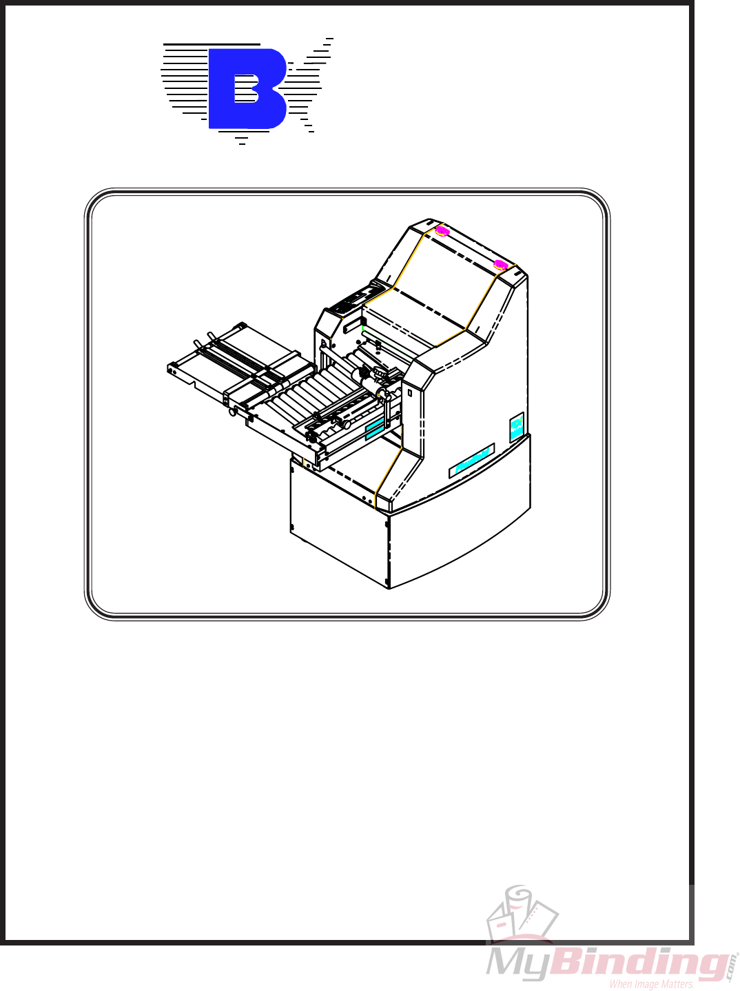
Your new Flexifold 8 Page Modular Folder has been designed to give you many years of useful service provided it is
installed, maintained, and operated according to the instructions in this manual.
Your Flexifold 8 Page is a unique and versatile paper folding machine, capable of folding paper measuring between 3 x
5 inches (7.6 x 12.7 cm) and 14 x 20 inches (35.5 x 50.8 cm), at speeds up to 27,600 sheets per hour of 8 1/2 x 11 (21.6 x
27.9 cm) and up to 41,000 sheets per hour of 3x5 (7.6x12.7 cm). The Flexifold can make four types of folds: single fold,
letter fold, fan fold, double-parallel fold, with the push of a button. (Note: There are also three (3) memory locations for
special folds that you may require).
2.0 SPECIFICATIONS
Model No Flexifold 8 Page
TP10432 PAGE 10
Figure 4.1-1
WARNING
Do not plug the power cord into an AC outlet until
the Flexifold 8 Page is fully assembled, adjusted and ready
to use. Unplug the Flexifold any time disassembly is
required.
4.0 ASSEMBLY
4.1 Main Unit
To assemble the Flexifold 8 Page unit, first remove
the four bolts holding it to the skid. Place the folder on the
stand (See Figure 4.1-1).
4.3 Delivery Table
To install the delivery table, insert the
delivery table with the drive wheel toward the fold rolls.
Slide the delivery table over both sets
of locating pins.
The first notch in the front part of the
delivery table should rest on the pins. Then drop the rear
notch down on the rear dowel pins.
Rotate the handwheel to check that the gears are
properly meshed.
Plug the delivery table into the table receptacle on
the input/output power assembly.
4.4 Cross Carrier Assembly Installation
Insert the Cross Carrier with the gears toward the
fold rolls. Slide the Cross Carrier table over both sets of
locating pins.
The first notch in the front part of theCross Carrier
should rest on the pins. Then drop the rear notch down on
the upper dowel pins.
Rotate the handwheel to check that the gears are
properly meshed.
4.5 Fold Plate Installation
WARNING
Unplug the AC power cord when installing or
removing fold plates.
The fold plates are interchangeable.
Each fold plate has an open end which faces toward
the fold rolls.
To install the fold plates, pivot the fold plate hold-
downs out of the way and slide the fold plate in position
so that the slots in the leading edge of the fold plate
engage the two locating pins in the side frames.
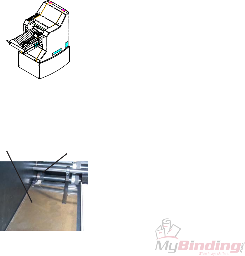
4.2 Transfer Table Mounting
Before mounting the transfer table into the first unit,
mount the 35T gear (FK0000824) from the accessory kit, on
the lower slitter shaft. Gear to be located with the hub against
the bearing race on the left hand side of the folder and
tighten the two set screws. (Guard removed for clarification)
See Figure 4.2-1.
Figure 4.2-1
Gear 35T
Transfer Table
PAGE 11 TP10432
The center notches should seat on the second set of
locating pins. Pivot the fold plate hold-downs back into
position to secure the fold plates.
Turn the handwheel to be sure that the fold plates
are properly installed and not rubbing on the fold rolls.
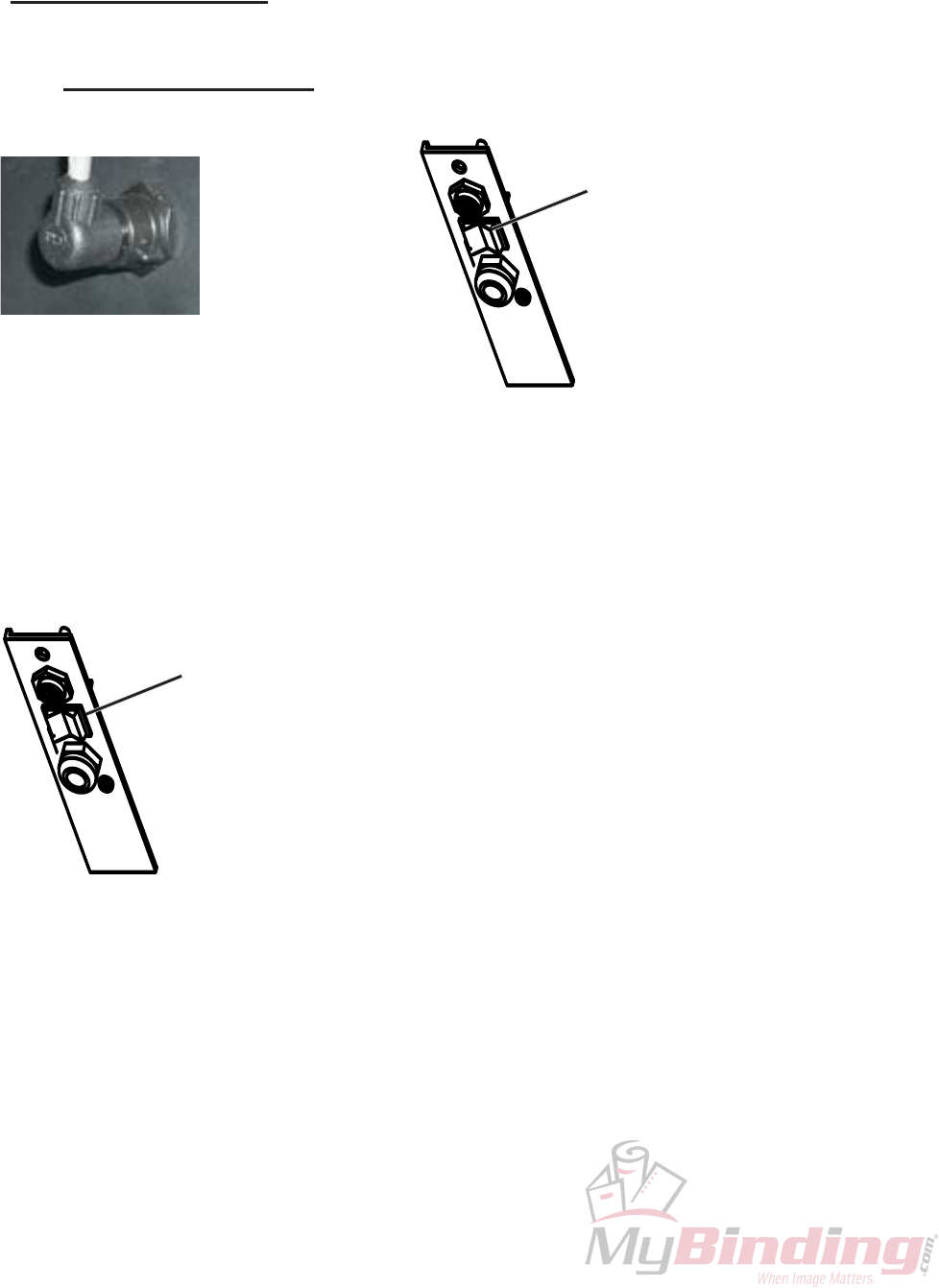
Plug the fold pan connectors into the side frame.
(See figure 4.5-1)
5.0 ELECTRICAL ACCESS
WARNING
Turn off the main power switch(See figure 5.0-1).
Unplug the AC power cord before attempting any
electrical repair.
The electrical controls are located in the left-hand
side cover. The handwheel must be removed for access to
these controls.
The cover can be removed by taking out the four
screws located on the inside of the frame.
Figure 4.5-1
Figure 5.0-1
Main Power/Reset
Switch
6.0 OPERATION
6.1 The Main Power/Reset Switch
The main power/reset switch (Figure 6.1-1) will
completely shut off all power to the operating system. This
will stop everything immediately.
Main Power/Reset
Switch
Figure 6.1-1
6.2 Starting the Production Job
The production job may be started after preparing the
folder by:
Setting the sheet size
Loading the feed table
Selecting the fold type
Setting Cross Carrier Side Guide
Folding may be stopped by pressing the “SHEET
START” button a 2nd time on the Parallel Unit.
6.3 Check Squareness of Fold
Examine the folded sheets on the stacker to make sure
that you are getting an even and square fold.
There is a skew adjustment on each plate to adjust for a
square fold on paper that is not cut square (See figure 6.3-1).
TP10432 PAGE 12
Figure 7.4-1
Fold Stop Guide
6.4 Use of Handwheel
The handwheel is used to help clear jams and for setup.
To use the handwheel, shut off the folder, pull out the
handwheel and turn it in either direction.
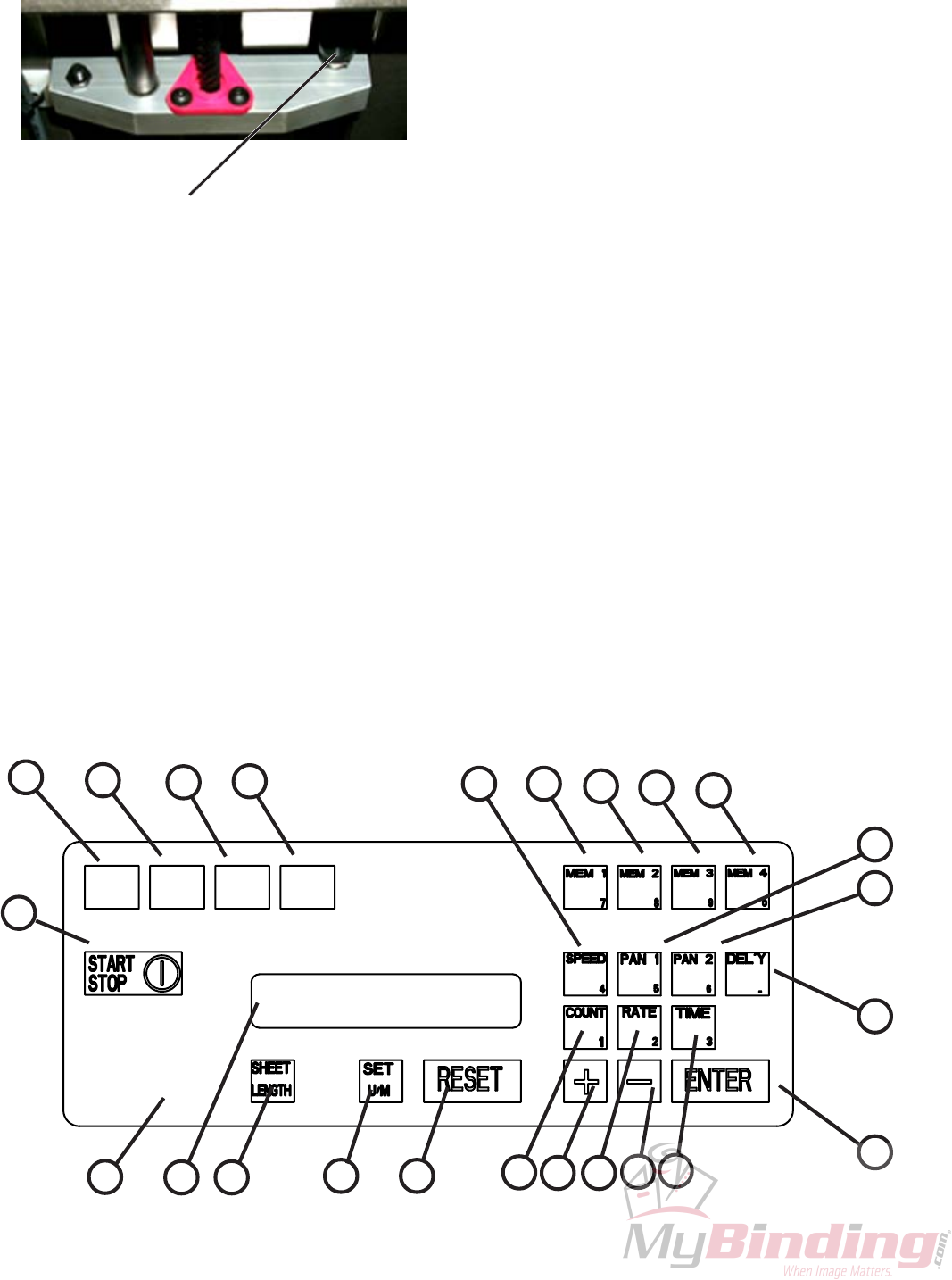
7.1 Button Identification (2nd function)
01) Count Select, (#1)
02) Rate Select, (#2)
03) Time Select, (#3)
04) Speed Adjust, (#4)
05) Plate #1 Adjust, (#5)
06) Plate #2 Adjust, (#6)
07) Memory 1 Set, (#7)
08) Memory 2 Set, (#8)
09) Memory 3 Set, (#9)
10) Sheet Jam Select, (#0)
11) Stacker Adjust
13) Data Enter
14) Decrement
15) Increment
16) Function Reset
17) Inches/Metric Unit Select
19) Sheet Mode Select
20) Alphanumeric Display
23) Folder Drive Start/Stop
24) Letter Fold Select
25) Z-fold Select
26) Double Half-fold Select
27) Half-fold Select
30) Operator Control Panel
7.0 OPERATOR PANEL
01 02 03
04
05
06
07 08 09 10
11
13
1415
1617
19
20
23
24 26 27
30
25

PAGE 13 TP10432
8.0 START UP
When power is applied, the system will first test all
LEDs, memory and display characters for 3 seconds.
After the self diagnostic phase, the display will show
the version number for 3 seconds.
If there are no error messages the display will go to the
jam detector screen if one of the jam detectors is disabled.
If none are disabled or after depressing enter, the display
will go to the initialization screen.
The initialization screen will remain for 10 seconds. If
the “+” button is not pressed during this time no initializa-
tion will occur. The display will go to the count screen.
If there is any question about folding accuracy, re-
initialize the system by turning off the power,then turn it
back on.
LEDs in the memory, or the fold type buttons will light
to indicate the last setting.
9.0 SETUP
Important note:
The operator control panel contains a numerical
keypad, which is automatically activated when a function
requires numerical data. The operator panel is color coded
to show this relationship. Numerical data is required for
Sheet length
Two pieces of information are required to setup a job,
assuming that initialization has previously been
accomplished; sheet length and fold type. Either order may
be used. Select the fold type first or the sheet length first
Note: When entering sheet length data use the length of
paper as it enters the 8 Page Unit.
9.1 Setup for a standard fold
Method 1: Picking fold type first:
To setup for a new fold, press a fold type button. For
example, to set a “Z” fold, press the ”Z” fold button. The
display will show the last job sheet length. If the sheet
length is not correct, you will have 5 seconds to begin keying
in the new sheet length and press the “ENTER” button (see
figure 1). If the sheet length is correct, you may press the
“ENTER” button and not wait 5 seconds before proceeding.
814MF
VERSION ****
FEEDER JAM DISABLED
INITIALIZATION
(+) YES (-) NO
TOTAL COUNT #######
I I I I I I I I I I I I I I I I I
I I I I I I I I I I I I I I I I I
SELECT FOLD
SHEET LENGTH ##.##
TP10432 PAGE 14
When the “ENTER” button is pressed, the fold plates
and stacker will move to their new position. While the fold
plate motor(s) are running, a PLEASE WAIT message will
be displayed.
When the motors have stopped, one of two screens will
be displayed.
If the sheet length data was changed, the single sheet
mode screen is displayed.
If the sheet length data was not changed, the count
screen will be displayed.
Method 2: Entering Sheet Length first:
Setup a new job by pressing the “SHEET MODE”
button. The Sheet Length screen will be displayed showing
the last set sheet length. You have the following options:
· 1.) Enter a new sheet length.
Note: Pressing the enter button will accept the
new data and eliminate any waiting time
before moving to the next function.
After 5 seconds the data will be accepted and the last
fold type indicator will start flashing. Select the desired fold
type by pressing the appropriate “FOLD TYPE” button.
After 5 seconds the selection will be accepted and the fold
plate stops will move to their new position. During this
period the “PLEASE WAIT” screen will be displayed.
When the folder has completed its movement, the count
screen will be displayed.
If the count screen is not displayed press the “SHEET
MODE” button to return to the production mode. The
count screen will be displayed.
·
PLEASE WAIT
SHEET LENGTH ##.##
PLEASE WAIT
TOTAL COUNT #######
Accept the displayed sheet length by pressing the “ENTER”
button.
2.) Do nothing.
After 5 seconds, the count screen will be displayed.
TOTAL COUNT #######
TOTAL COUNT #######
PAGE 15 TP10432
RECALL
(N) - (Y) ENTER
RECALL
(N) - (Y) ENTER
STORAGE
(N) - (Y) ENTER
9.2 Setting up a special fold.
This machine has 3 memory locations that can be used
to store special fold settings. These will store the plate
settings, the stacker wheel location, and the speed setting for
a fold.
9.2.1 To save a nonstandard fold in a memory
location 3
Set up the fold as you normally would. Once the speed
and folds are set the way you want, press a “MEMORY
SET” button. Recall will appear in the display. Press the
(-) button to get to the STORAGE screen.
9.2.2 Recall a fold saved in memory location.
Press the “MEMORY SET” button that corresponds
to the memory location you wish to recall. RECALL will
appear. Press the ENTER button.
9.3 Starting Production:
After the sheet length and the fold type has been
selected, production is started by:
Starting the main drive (press “DRIVE”),
·
The 8 Page Drive must be started first then the Parallel
unit. The Parallel Unit will not start if the 8 Page Unit is
not running.
·
Notes:
If the wrong “FOLD TYPE” button is pressed, you
can either press the “RESET” button instead of the
9.3 Continued
“ENTER” button or press the correct “FOLD TYPE” button,
then the “ENTER” button.
After every new set up the machine speed will always be
reset to 60%.
The fold type status LED, when lit constantly, indicates
that the fold plates are set for this type of fold.
Any time the folder is running and a change is made that
causes the fold plate stops to move; the main drive will stop.

TP10432 PAGE 16
TOTAL COUNT #######
RESET
TOTAL COUNT #######
10.0 COUNTER OPERATION
During normal operation, the display should show the
total count (maximum count 9,999,999), This display is
known as the count screen.
10.1Resetting the total count
To reset the total count press the “RESET” button,
then press the “COUNT” button.
10.2 Rate
The “RATE” button is used to display the average
pieces per hour, both current and average since the last total
counter reset.
Pressing the “RATE” button will change the display
to the rate screen consisting of two lines. The top line is the
current rate. It will have a 5 digit display, and will refresh
every 6 seconds. The second line will show the average
pieces per hour since the last total counter reset. This line
will also have a 5 digit display, and refresh every 30
seconds.
The display will stay in this mode until another mode
button is pressed. The “ENTER” and “RESET” buttons
will have no affect in this mode.
NOTE: Every time the total count is reset the
average rate per hour will also be reset.
NOTE: If a button is not pressed within 2 minutes the
machine will return to the operating mode.
CURRENT RATE #####
AVERAGE RATE #####

PAGE 17 TP10432
NOTE: If a button is not pressed within 2
minutes the machine will return
to the operating mode.
11.0 FOLDER OPERATION
11.1 Time
The “TIME” button will display the time since the
last total count reset and the total hours that the main drive
has been on, the customer can not reset this meter.
Both hour meters will increment only when the folder
is running. The main power will have no affect on these
meters.
NOTE: Every time the total count is reset the
job run time should also be reset.
Pressing the “TIME” button will change the display
to the time mode. In this mode the first line of the display
will show job run time and have a 4 digit capability to show
the number of hours since last reset. The second line will
show total hours and have a 6 digit capability to show the
total hours on the machine.
The “COUNT” button can be used to go back into the
count screen from the rate or time screen.
11.2 START/STOP button
In the normal operating mode pressing the “START/
STOP” button will activate the main drive motor and the
LED in the button will come on. Pressing the “START/
STOP” button again will deactivate the main drive motor
and turn off the LED.
JOB RUN TIME ####
TOTAL HOURS ######
TOTAL COUNT #######
TP10432 PAGE 18
NOTE: If a button is not pressed within
2 minutes the machine will return
to the operating mode.
11.3 Speed
The speed of the machine can be changed by pressing
the “SPEED” button while the main drive motor is running
or stopped.
Using the “+” and “-” buttons, to adjust the speed.
The “+” button will increase the speed gradually, as
long as the button is depressed. Once the folder reaches it's
maximum speed a message will be displayed until the
ENTER button is pressed.
The “-” button will decrease the speed gradually, as
long as the button is depressed.
Once the folder reaches it's minimum speed a message
will be displayed until the “ENTER” button is pressed.
Full speed range travel of the motor takes 10 seconds.
Press the “ENTER” button to return to normal operation.
11.4 Fold Plates
The fold plate can be set at any time from the operat-
ing mode by pressing the “PLATE” button that corresponds
to the fold plate which needs to be adjusted.
For example if you need to make an adjustment to the
number 2 fold plate you would press the “PLATE 2”
button.
Next use the “+” and “-” buttons to move the stop into
position. Once either button is pressed the display will
change to display the actual location of the plate stop.
SPEED 60%
CHANGE WITH +/-
MAXIMUM SPEED
CHANGE WITH +/-
MINIMUM SPEED
CHANGE WITH +/-
TOTAL COUNT #######
PAN 2 STOP 05.00 IN
CHANGE WITH +/-
PAGE 19 TP10432
Pressing the “+” button once will increment the plate
stop .010". Holding it down for more than 2 seconds will
increment the plate stop continuously at slow speed. Holding
the “+” button down for more than 5 seconds will increment
the plate stop continuously at high speed until you release
the button or the plate stop hits the home position switch.
Pressing the “-” button once will decrement the plate
stop position .010". Holding it down for more than 2
seconds will decrement the plate stop position at slow speed.
Holding the “-” button down for more than 5 seconds will
decrement the plate stop position at high speed until you
release the button, or the plate stop hits the deflect position
switch.
Pressing the “ENTER” button will return you to
normal operation.
11.5 Stacker wheels
The stacker wheels can be set at any time from the
operating mode by pressing the “STACKER” button.
For example if you need to make an adjustment to the
stacker wheels, press the “STACKER” button during
operation.
Next use the “+” and “-” buttons to move the stacker
wheels into position.
Pressing the “+” button will increment the stacker
wheels continuously at slow speed. Holding the “+” button
down for more than 2 seconds will increment the stacker
wheels continuously at high speed until you release the
button, or the stacker wheels reach their outer limit. The
system will track the stacker wheel location and if they reach
the stop, the drive will be disabled and a message will be
displayed for 5 seconds after the “+” is released.
NOTE: To change from English to Metric, press the
“U/M” button. Now all the dimensions will
be in metric. Thesetting will remain until this
procedure is repeated.
NOTE: If a button is not pressed within
2 minutes the machine will return
to the operating mode.
TOTAL COUNT #######
DELIVERY 04.00 IN
CHANGE WITH +/-
STACKER WHEELS
AT MAXIMUM LIMIT
DEFLECT POSITION
TP10432 PAGE 20
Pressing the “-” button will decrement the stacker
wheels position at slow speed. Holding the “-” button down
for more than 2 seconds will decrement the stacker wheels
position at high speed until you release the button or the
stacker wheels hit the home position. Once the stacker
wheels have reached the home switch the drive is disabled
and a message will be displayed for 5 seconds after the “-”
is released.
After the stacker wheels are in position press the
“ENTER” button. This will return you to the operating
mode.
11.6 Paper Jams
Should a jam-up occur, the machine will shut off and
display will indicate where the jam occurred. Anytime a jam
indication is showing in the display you can press the
“STACKER” button and the stacker wheels will move to
the end of the table to make clearing any paper jammed in
the machine easier. Try to determine the cause of the jam
and correct it before pressing the “RESET” button. Pressing
the “RESET” button will clear the jam message, return the
stacker wheels to there original position and re-enable the
drive.
STACKER WHEELS
AT MINIMUM LIMIT
TOTAL COUNT #######
FEEDER JAM
DELIVERY JAM
11.7 Shutting Off Jam Detectors
1) To enter jam detector mode, depress the “SET JAM” button:
NOTE: Use the “+” button to toggle between
enable and disable of the specific jam
detector.
Use “-” button to make no change.
CLEARED. PRESS RESET
PAGE 21 TP10432
Display shows:
OR
2) When the “+” or “-” button is depressed,
Display shows:
3) When the “+” or “-” button is depressed,
Display shows:
FEEDER JAM ENABLED
DISABLE ? (+) YES (-) NO
EXIT JAM ENABLED
DISABLE ? (+) YES (-) NO EXIT JAM DISABLED
ENABLE ? (+) YES (-) NO
TOTAL COUNT #######
FEEDER JAM DISABLED
ENABLE ? (+) YES (-) NO
OR
TP10432 PAGE 22
Figure 12.1-2)
Slide the perforator collar and blade holder to the
desired position on the slitter shaft. Re-install the pullout tire
assemblies on the right end of the upper and lower shafts.
Lock the slitter shafts in place by pushing in the knob
as you align the slitter shafts with the slitter shaft journal
assembly. Tighten the knurled knob. Then lock the blade
holder and perforator collar into position with the brass-
tipped set screw. (Item 4, Figure 12.1-2) Lock the pullout
tire assemblies in place by tightening the brass tipped set
screws. (Item 1, Figure 12.1-2)
The perforator stripper fits onto spreader bar above
the slitter shaft assembly and next to the perforating blade.
(See Figure 12.1-3) This strips the paper off for delivery
and prevents it from wrapping around the perforator blade.
12.0 PERFORATING, SCORING &
SLITTING
In addition to folding, your Flexifold 8 Page can perfo-
rate, score and slit. WARNING
Unplug power supply before working on equipment.
Be careful when handling perforator and slitting
blades. They are extremely sharp.
12.1 Perforating
The Flexifold can be used to perforate either the
folded sheet (to assist in making a right-angle fold) or to
perforate sheets delivered flat. BAUMFOLDER supplies
one standard 41-tooth perforator blade. Additional perfora-
tor blades are available through the BAUMFOLDER Parts
Department.
On the operator side of the folder there is a knurled
knob beside the hand wheel. (See figure 12.1-1) This knob
holds the slitter shaft assembly in place. Loosen the knob by
turning counter-clockwise approximately 6 full turns.
Pull the knob toward you, leaveing about 1 5/8” gap at
the right end of the slitter shafts. This gap permits the
removal and installation of the slitter shaft accessories.
Loosen the setscrews (Item 1, Figure 12.1-2) in the
pullout tire assemblies on the right end of the upper and
lower shafts and remove the pullout tire assemblies.
The perforator blade, sharp surface down, should be
mounted loosely to the blade holder collar.(Item 2 & 3,
Figure 12.1-2) Always be sure that the flat side of the blade
is against the blade holder. Loosen the brass-tipped set
screws (Item 4, Figure 12.1-2) in the blade holder before
attempting to place them on the slitter shafts.
The perforating blade holder assembly is then slid
onto the upper slitter shaft. Tighten the screws (Item 5,
Figure 12.1-2) holding the perforator blade to the blade
holder, aligning the blade to the holder. This allows for free
horizontal movement on the shaft.
Slide the grooved perforator collar onto the lower
slitter shaft. The flat side of the perforator blade should just
touch the side of the groove in the perforator collar. (Item 6,
Figure 12.1-1
Slitter Shaft Knob
Figure 12.1-2
1
2
3
4
5
6
Figure 12.1-3
PAGE 23 TP10432
Figure 12.2-1
For a wide, well-rounded score, use the two steel
scoring collars. (See Figure 12.2-1) Sharpness and the depth
of the score can be controlled by regulating the distance the
collars are placed away from the scoring blade.
The scoring collars can also be placed on either side
of the rubber scoring collar. The two collars can be com-
pressed against the rubber collar, causing the rubber to bulge
up for a deeper score. (See Figure 12.2-2)
Figure 12.2-2
Figure 12.3.-1
12.2 Scoring
The Flexifold can be used to score a sheet and
deliver it flat, or to score a sheet after a fold or folds have
been made.
To ensure accuracy in making right-angle folds,
always score the sheet where the fold is to be made. This
applies in all instances when a perforator cannot be used.
Access and installation to the slitter shaft assembly is
the same proceedure as described in the previous section
on slitting.
Attach the scoring blade loosely to the blade holder
for mounting on the slitter shaft. Scoring blades can be
mounted on either the upper or lower slitter shaft. Once on
the shaft, tighten the screws, aligning both the blade and
the collar. This allows free horizontal movement on the
shaft. Scoring blades should be placed so that the fold will
be made with rather than against the scoring, or, in a
continuing direction to the pressure of the crease that has
been applied by the scoring blade.
12.3 Slitting
NOTE: Slitting accessories are optional on your
Flexifold and can be ordered from your BAUMFOLDER
Parts Department.
The Flexifold can be used to cut folded or flat sheets
apart. The general setup for blades and collars is shown in
(Figure 12.3.1). Two or more cuts may be made if duplicate
sets of cutters are used.
Use care in mounting slitter blades to the collars in
order to avoid ragged edges during slitting operations.
Ragged edges can be caused by two conditions:
1) Nicks or burrs on the collars or blades. Remove
carefully by filing or using a fine piece of emery cloth.
2) Incorrect mounting of blades caused by tightening
with the wrong type of screw. Always use flat head screws
on the side of the blade and blade holder collar, which are
countersunk.
Before tightening the blade to the collar, slide the
blade with the collar loosely attached on the end of the shaft.
Then tighten securely, thus aligning both the blade and
collar, allowing free horizontal movement along the shaft.
Place the blade, mounted on the collar, on the upper
shaft in the proper position where the cut is to be made.
Then move the blade and collar on the lower shaft so that
the two flat edges of the blades are pressed snugly together.
Too much space between the blades will produce a ragged
cut.
Space the rubber pull-out tires to support the sheet.

TP10432 PAGE 24
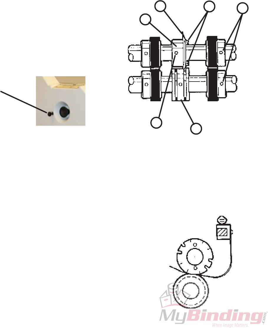
13.4 Photo Eyes
Occasionally wipe off both photo eyes with a dry
cloth.
13.5 Cleaning The Fold Stop Guides
The fold stop guides should be cleaned once a week
with a dry cloth to keep the plate moving properly.
13.6 Replacement Parts
To order replacement parts for your Flexifold Air
Feed, contact BAUMFOLDER Parts Department toll free,
800-543-6107.
Always be sure to give the model number and serial
number of your Flexifold to ensure receiving the proper
parts.
13.0 MAINTENANCE
13.1 Maintenance and Care of your 814MF
The Flexifold Air Feed has been designed to give you
years of useful service, provided you maintain it according
to these instructions.
13.2 Cleaning of Fold Rolls
Periodically wipe off the rubber surface of the fold
rolls using an approved solvent such as Surewash or its
equivalent. Surewash is available from BAUMFOLDER in
1-quart (P/N 24108-001) and 1-gallon (P/N 24108-002)
containers. A complementary bottle of Surewash is included
with your machine.
13.3 Cleaning Filters
The filters on the pump should be checked periodi-
cally and cleaned as needed. The filters can be reached by
unscrewing the filter jars.
PAGE 25 TP10432
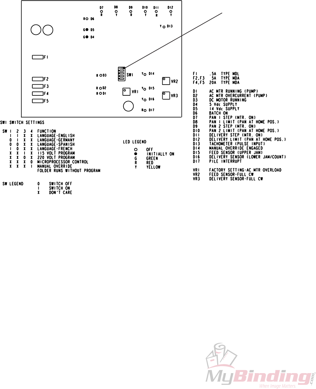
14.0 LANGUAGE SELECTION
Switch location, on the electronic board, for lan-
guage and voltage selection settings.
Settings Switch

TP10432 PAGE 26
15.0 DISPLAY MESSAGES
The following are other display messages that may
appear.
HOME NOT REACHED
PRESS RESET
NO TACH. CHECK
MOTOR, BELTS, ENCODER
OUT OF RANGE
CHANGE +/-
KEYBOARD MISSING
PAPER SIZE INCORRECT
PRESS RESET
INSTALL DELIVERY
OR PRESS RESET
INSTALL PLATE NO.1
OR PRESS RESET
INSTALL PLATE NO.2
OR PRESS RESET
FOLDER OVERLOAD
PRESS RESET
BAD KEYBOARD
PAN 1 STOP 05.00 IN
CHANGE WITH +/-
PLATE NO.

PAGE 27 TP10432
SUREWASH
16.0 MATERIAL SAFETY DATA
SHEET
NOTICE: Surewash is a product of RBP
Chemical Corporation, 150 S. 118th St., P.O. Box
14069, Milwaukee, Wisconsin 53214-0069. Tel. 414/
258-0911, 800/558-0747.
Inhalation of high concentrations may cause
respiratory tract irritation and may affect central
nervous system. May cause skin irritation. Chronic
over-exposure to many petroleum hydrocarbons
may cause liver or kidney injury. May cause eye
irritation.
Emergency & First Aid Prodedures:
Skin Contact: Wash affected area with soap
and water. Remove contaminated clothing.
Eye contact: Flush eyes with water for at least
15 minutes. Consult a physician.
Inhalation: Remove to fresh air. Restore
breathing if required. Get medical attention.
Ingestion: DO NOT induce vomiting. Get medi-
cal attention.
Carcinogenicity: None of the ingredients in this
product are listed by IARC, NTP, or OSHA as car-
cinogenic.
Signs and Symptoms of Over-exposure: Head-
ache, dizziness, nausea, irritation of the mucous
membranes, respiratory tract irritation or mild nar-
cosis at high concentrations.
Medical Conditions Aggravated by Exposure:
May aggravate an existing dermatitis.
PRECAUTIONS FOR USE AND DISPOSAL
Spills: Small spills can be soaked up with suit-
able absorbent. For large spills, dike the spill and
pump to salvage tank.
Waste Disposal: Incineration or absorbent dis-
posal according to local, state, or federal regulations.
Special Storage/Handling Precautions: None
CONTROL MEASURES
Respiratory Protection: Organic vapor respira-
tor for concentrations above the TLV.
Ventilation: Mechanical
Eye Protection: Recommended
Gloves: Recommended, butyl, rubber or neo-
prene.
Other: Eye bath or safety shower should be
located in the work place when working with chemi-
cals.
*ND = No data found or not determined.
The information contained herein is furnished
without warranty of any kind. Users should con-
sider this data a supplement to other information
gathered by them and are responsible for complete-
ness of information to assure proper use of these
materials and the safety and health of their employ-
ees.
H M I S RATING
Health: 1
Flammability: 2
Reactivity: 0
Personal Protection: 8
HAZARDOUS INGREDIENTS
Name: Medium Aliphatic Solvent Naptha
(Syn: 140 HF Mineral Spirits)
CAS#: 64742-88-7
ACGIH TLV: 100ppm
OSHA PEL: 500ppm
%: <95
PHYSICAL/CHEMICAL CHARACTERISTICS
Boiling Point: ND
Solubility in Water: Insoluble
% Volatiles (by vol.): 95
Specific Gravity: 0.786
Appearance and Odor: Clear, light blue liquid
with pleasant odor.
FIRE AND EXPLOSION HAZARD DATA
Flash Point: 140' F
Extinguishing Media: CO2, Dry chemical,
Foam
Special Fire Fighting Procedures: Wear self-
contained breathing apparatus for any fire
involving chemicals.
Unusual Fire and Explosion Hazards: None
REACTIVITY DATA
Stability: Stable
Incompatibility: Strong oxidizers
Hazardous Decomposition By-products: Car-
bon dioxide/monoxide
Hazardous Polymerization: Will not occur
Conditions to Avoid: Heat, Sparks, and Open
Flames
HEALTH HAZARD DATA
Routes of Entry: Inhalation, Primary; Skin,
Secondary; Ingestion, Unlikely
Health Hazards Acute and Chronic: Chronic
To order Surewash call toll free, 800/543-6107
Part numbers: 24108-001 (quart) & 24108-002
(gallon)
TP10432 PAGE 28
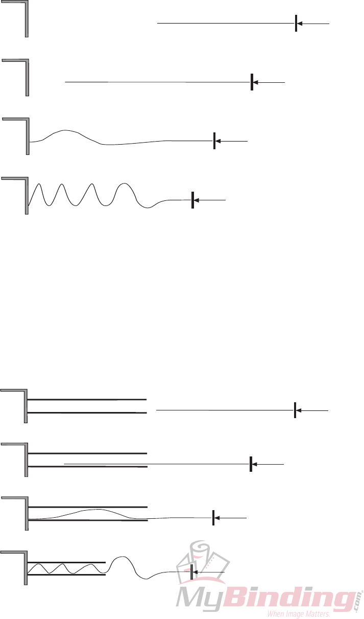
17.0 BASIC THEORY OF BUCKLE
FOLDING
If a sheet of paper is laid on a flat surface and driven into
a stationary object, a buckle or series of buckles will form
along the surface of the sheet.
If the sheet of paper is pushed into a narrow channel
before butting up against the stationary object, the buckles that
form within the channel will be of a much smaller size than
free-forming buckles. At the end of the channel, however,
larger buckles will again start to form.
PAGE 29 TP10432
If the channel is angled to produce a downward pressure,
and two folding rollers, spinning as indicated, are placed close
to the end of the channel, the larger buckles that start forming
there will always be formed downward and be pulled into the
rollers, compressing into a fold.
1
2
MAIN
DRIVE
FOLD PAN
1
2
MAIN
DRIVE
FOLD PAN
1
2
MAIN
DRIVE
FOLD PAN
TP10432 PAGE 30
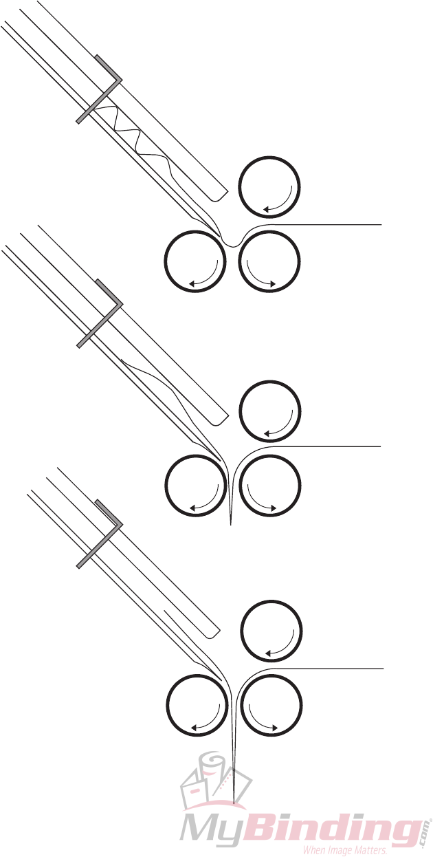
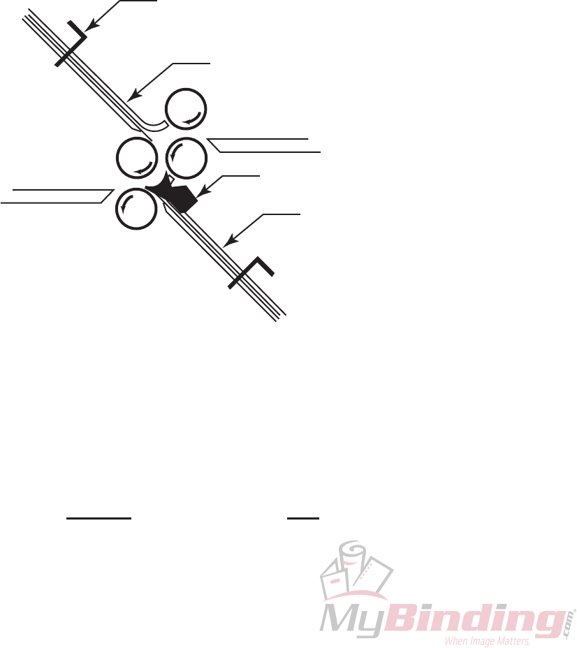
On a buckle folder, the sheet is laid flat on a feed table
and then enters the fold plate assembly where it comes to a
stop against the stationary sheet stop. A series of buckles
then forms throughout the sheet. The buckles whithin the
fold plate are kept very small by the narrow channel design.
The buckles at the end of the fold plate, however, will be
larger. The fold plates and fold rollers are configured such
that the large buckle will always form downward, where it
can be grabbed by the fold rollers and compressed into a
fold.
FIGURE 1
Fold Pan Fold
#1 UP
#2 DOWN
1
2
3
MAIN
DRIVE
SHEET STOP
FOLD PLATE #1
DEFLECTOR
FOLD PLATE #2
FEED TABLE
DELIVERY
Look at figure 1. You can see that fold plate #1 is
angled upwards. Because of this and the configuration of
the fold rollers, sheets fed into the #1 plate will always be
folded up (i.e. so that the “up” surface of the sheet is folded
into contact with itself).
Likewise, because fold plate #2 is angled down, sheets
fed into it will be down-folds; the “down” surface of the
sheet will be folded into contact with itself. The picture
shows the plate #2 deflector in position. The sheet does not
enter plate #2, deflected, producing a single fold.
