MyBinding Duplo 915 920 Service Manual User
2013-06-04
User Manual: MyBinding Duplo-915-920-Service-Manual
Open the PDF directly: View PDF ![]() .
.
Page Count: 96


PAPER FOLDER
DF-920/915
MAINTENANCE MANUAL

12H-M12M0-0309-0
TABLE OF CONTENTS
CHAPTER 1 MECHANISM
1. Outline of Machine ..........................................1-2
2. Outline of Mechanisms and Adjustments........1-6
3. Periodic Inspections ........................................1-50
4. Troubleshooting Guide
(Mechanical Causes) ...................................... 1-52
CHAPTER 2 ELECTRICAL
COMPONENTS
1. Block Diagram of Structure and Outline of
Each Block ......................................................2-2
2. Errors and Causes ..........................................2-10
3. Maintenance Mode .........................................2-15
4. Backup Data Form ..........................................2-28
5. Initializing the Memory .................................... 2-30
6. Precautions on Replacing the MC Unit ...........2-31
7. Upgrading the Program Version .....................2-32
8. Overall Schematic Diagram (DF-920) ............. 2-33
9. Overall Schematic Diagram (DF-915) ............. 2-34
10. Wiring Diagram 1/2 (DF-920) .......................... 2-35
11. Wiring Diagram 2/2 (DF-920) .......................... 2-36
12. Wiring Diagram 1/2 (DF-915) .......................... 2-37
13. Wiring Diagram 2/2 (DF-915) .......................... 2-38
About This Manual
This maintenance manual is intended for those familiar with maintenance work of the Duplo paper folder DF-500
series. Sections found in the maintenance manual of the DF-520N have been omitted. Refer to the maintenance
manual for DF-520N for these sections.
Precautions on Maintenance
Disconnect the power cord from the outlet to ensure safety when implementing maintenance work.
Use a non-flammable type air spray. Read the instructions on use carefully and be sure to observe them.
Notify users who have remodeled this unit that they are required to ensure safety at their own responsibility.
Consumables Used for Maintenance (Grease, etc.)
This manual lists the standard products and specifications for consumables used in maintenance such as grease, etc.
If these products are not available, use products that comply with the specifications indicated.
“MOLY KOTE” is either the trademark or registered trademark of U.S. Dow Corning Corporation, “Loctite” that of U.S. Henkel Loctite Corporation,
“NITOFLON” that of Japan NITTO DENKO Corporation, and “Three Bond” that of Japan Three Bond Co., Ltd. Other company and product names
in the manual may be the trademark or registered trademark of their respective countries.

1-1
12H-M12M0-0309-0
CHAPTER 1
MECHANISM
1. Outline of Machine ......................................... 1-2
1-1. Names of Parts ....................................... 1-2
1-2. Layout of Folding Plates and
Folded Size by Folding Mode ................. 1-4
2. Outline of Mechanisms and Adjustments ... 1-6
2-1.
Folding Section and Drive Mechanism ....
1-6
2-2. Paper Feed Tray ..................................... 1-15
2-3. Separating Mechanism ........................... 1-23
2-4. Paper Feed Inlet ..................................... 1-24
2-5. Paper Ejection Mechanism ..................... 1-26
2-6. Folding Plates .........................................1-29
2-7. Exterior and Detection Switches ............. 1-47
3. Periodic Inspections ......................................1-50
3-1. Inspection Points and Procedure ............ 1-50
3-2. Other General Precautions ..................... 1-50
4. Troubleshooting Guide
(Mechanical Causes) ..................................... 1-52
4-1. When Paper is Conveyed Skewed ......... 1-52
4-2. When Paper Wrinkles ............................. 1-52
4-3. When Abnormal Sounds (Metal Sliding
Sounds) are Produced During Rotation
of Folding Rollers .................................... 1-52
4-4. When Stacker Belt Rotates Heavily ........ 1-52
4-5. Stopping Position of Paper Lead Edge
Does Not Stabilize During Paper Feed,
and Paper Jams Near Paper Feed Inlet
Sensor .................................................... 1-53
4-6. When Paper Slips Frequently ................. 1-53
4-7. When Continuous-feed Occurs
Frequently with Small Paper
(B7, INV, etc.) .........................................1-53
4-8. When Stacker Belt Slips ......................... 1-53
4-9. When Folding Stopper Moves
Abnormally Slow ..................................... 1-53
4-10. When Folding Misalignment Along
Vertical Length of Paper is Large ........... 1-54
4-11. When Folding Misalignment Along
Sides of Paper is Large .......................... 1-54
4-12. Paper Jams at Folding Unit or
Flattening of Folded Line Occurs During
Single Folding and When Thick Paper is
Used, or Folding Wrinkle Line is Formed
at Folded Line with Thin Paper ............... 1-54
4-13. Paper Jams at Folding Unit or
Flattening of Folded Line Occurs
During Folding Modes Other Than
Single Folding and When Thick Paper
is Used .................................................... 1-54
4-14. When Motor Lock of Folding Plate 2
Occurs .................................................... 1-54
1-2
12H-M12M0-0309-0
1. OUTLINE OF MACHINE
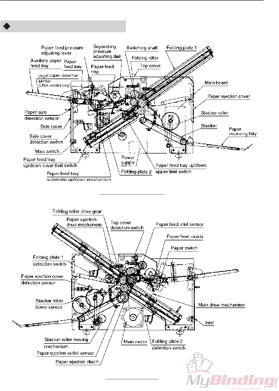
1-1. Names of Parts
DF-920
Front view (Operating side)
Rear view (Drive side)
1-3
12H-M12M0-0309-0
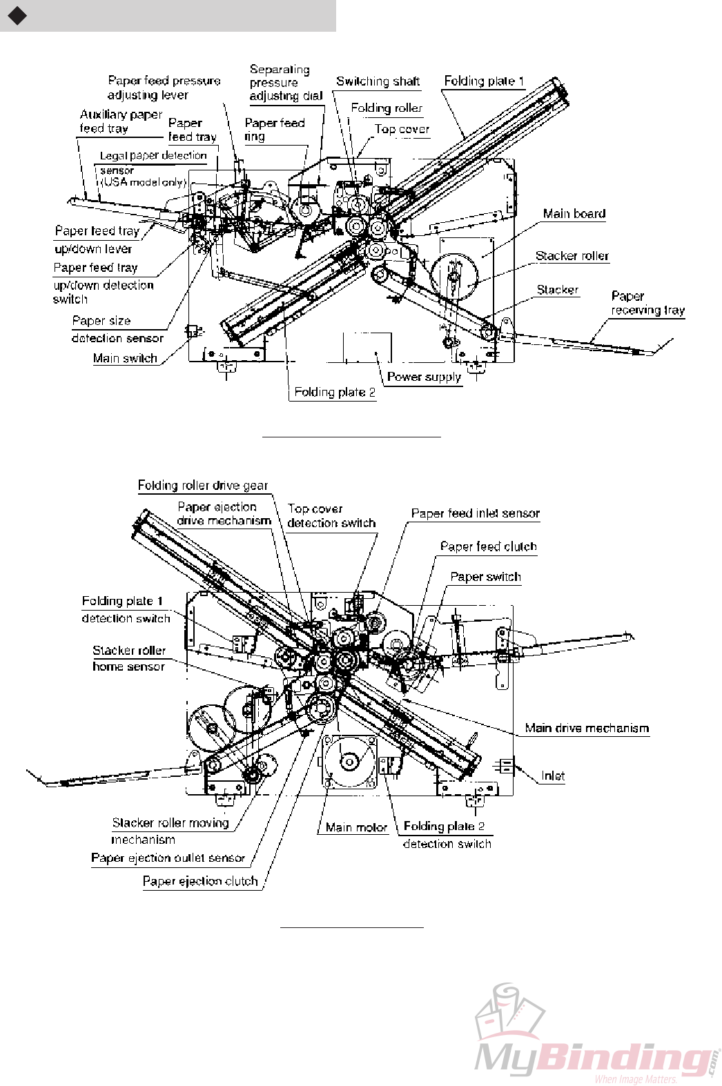
DF-915
Front view (Operating side)
Rear view (Drive side)
1-4
12H-M12M0-0309-0
1
23
4
A
A
B
B
Paper
ejection
section
Folding stopper
Folding rollers 1 to 4
Paper feed ring
Paper feed tray
Folding plate 1
Stacker roller
Folding stopper
Folding plate 2
Flow of paper
1-2. Layout of Folding Plates and Folded Size by Folding Mode
The DF-900 series is equipped with folding plates to ensure smooth paper conveyance from paper feed to ejection.
This section describes the layout of folding plates and folded size by folding plates 1 and 2 in each folding mode.
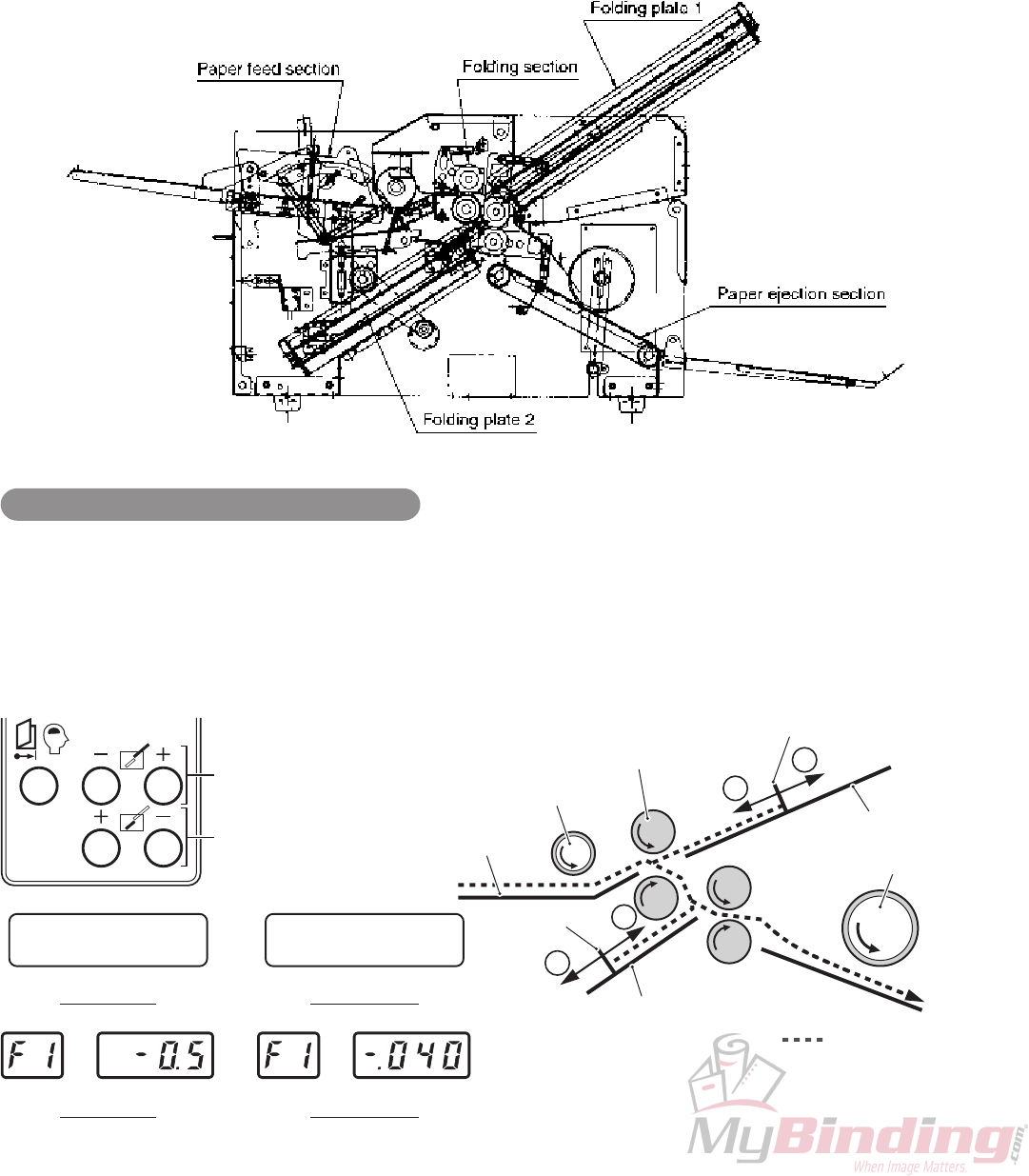
1-2-1. Layout of folding plates
As seen from the control panel side, the paper feed section is located at the top left, folding plate 1 at the top right,
folding plate 2 at the bottom left, and paper ejection section at the bottom right.
This layout subjects paper to the least stress from paper feed to ejection. However, because folding plate 2 is located
at the lower side of the paper feed section, this makes adjustment of the folded size by hand difficult, and all folded
size adjustments must be performed on the control panel.
Adjusting the folded size (folding position)
Folded size (folding position) is adjusted by moving the folding stopper using the folding stopper adjusting keys of
folding plates 1 and 2 on the control panel.
Each time the key is pressed, the folding stoppers move by 0.125 mm (0.005"). The window shows the distance
moved. At this point, the folding stoppers do not move. They move when the start or test key is pressed.
Pressing the “+” key moves the folding stoppers of folding plates 1 and 2 in direction A shown in the figure. Pressing
the “–” key moves them in direction B.
A4 +3.O/-1.O
STAND BY
Folding plate 1
folding stopper adjusting key
Folding plate 2
folding stopper adjusting key
LTR +.O3O/-.O4O
STAND BY
DF-920 UK DF-920 USA
DF-915 UK DF-915 USA

1-5
12H-M12M0-0309-0
1-2-2. Folded size by folding plates 1 and 2 in each folding mode (theory)
The values in the table below are theoretical values. In actual use, folded size is finely adjusted according to the
folding mode to prevent dog ears and curling of paper.
Folding mode Single
fold
Folded size by folding plate 1
(Ratio to paper length)
Folded size by folding plate 2
(Ratio to paper length)
1/2
0
Double
fold
1/2
1/4
Irregular
accordion
fold
1/4
1/4
Letter
fold
2/3
1/3
Accordion
fold
1/3
1/3
Brochure
fold
3/4
1/4
Example: Letter folding A4 (Letter) paper
A4 (Letter) paper length: 297 mm (11")
Folded size by folding plate 1: 199 mm (7.37") (About 2/3 of paper length)
Folded size by folding plate 2: 100 mm (3.70") (About 1/3 of paper length)
∗Measure the folded size at the center of the paper.
Folded size by folding plate 1
199 mm (7.37")
Measuring point
(Center)
99 mm
(3.67")
98 mm
(3.63")
Folded size by folding plate 2
100 mm (3.70")
Paper feed direction
∗ ( ) shows the folded size for letter size paper.
1-6
12H-M12M0-0309-0
2. OUTLINE OF MECHANISMS AND ADJUSTMENTS
2-1. Folding Section and Drive Mechanism
The folding section is the most basic paper folding mechanism. It is composed of folding rollers, press lever, reference
stoppers, etc.
The drive mechanism distributes driving force from the main motor to the folding rollers, paper feed mechanism, and
stacker mechanism.
2-1-1. Cleaning the folding rollers
Clean off dirt on the surface of the idler roller, center press roller, and folding rollers 1 and 2 with alcohol. Use of other
solvents may deform the surface of the rubber roller.
2-1-2. Replacing folding rollers
(1) Removing/attaching order of folding rollers
Remove in the order of idler roller, center press roller, folding roller 1, and folding roller 2.
Attach in the reverse order of the above.
As the center press roller is incorporated with a switching shaft unit, be careful not to deform the
switching angle during removal.
As the folding rollers are incorporated with keys, collars, and flat pins for securing the drive gears (helical
gears), be careful not to lose these during removal.
Make sure that there is no grease or oil on the side of the switching shaft passed by paper.
NoteNote
(2) Attaching the press lever
Apply a small amount of oil to the area where the
press reference pillar and press lever are
connected.
(Orelube G90-140: Equivalent to ISO #460)
(3) Attaching the reference stoppers
The reference stoppers minimize deformation of
the rubber roller (nip), maintain appropriate
distance between the folding roller shafts, and
maintain backlash of the drive gear (helical
gear).
Secure the reference stoppers in the order of
idler roller, folding roller 1, and folding roller 2
with the folding rollers in contact.
Always turn off the power when cleaning. Also take precautions against fire and ensure ventilation when using
alcohol.
NoteNote

1-7
12H-M12M0-0309-0
(4) Attaching the drive gear (helical gear) of folding
roller
Attach the press spring T and regulated stopper
after attaching the drive gear. This helps
facilitate attaching of the drive gear.
Attach the key, flat pin, and deceleration pulley
for securing the drive gear to the center press
roller.
Attach the key, collar, timing pulley, and thrust
regulated washer for securing the drive gear to
the idler roller.
Attach the key, collar, and thrust regulated
washer for securing the drive gear to folding
rollers 1 and 2.
The teeth of the helical gear is subject to force in
the thrust direction during rotation. When
securing the thrust regulated washer with
screws, check that the helical gear does not
move in the thrust direction.
Using gears in the thrust play state may cause
abnormal wear on the gear teeth side and
wrinkles of the paper due to paper slipping.
1-8
12H-M12M0-0309-0
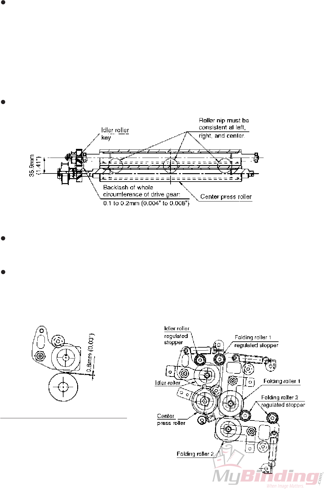
After attaching the drive gear, apply press force to all folding rollers, and check the following points.
• Rotate the folding rollers for one round, and check that there is uniform roller nip (surface hollowing
amount of rubber roller) in all directions (left, right, center) between all folding rollers.
• Make sure that gear engagement is ample, and the rollers rotate smoothly.
At this time, if the nip amount on the left and right differs between folding rollers, paper may slip.
• Roller nip : 0.1 mm (0.004") (folding roller shaft distance: 35.9 mm (1.41"))
• Folding roller drive gear backlash: 0.1 to 0.2 mm (0.004" to 0.008") for above distance between folding
roller shafts
Check the gear backlash with the folding roller key removed.
Apply grease to the whole circumference of the drive gear. (Orelube G1650: Equivalent to NLGI #1)
(5) Attaching the regulated stopper
The regulated stopper helps prevent inference between teeth resulting from excess distance between the
drive gears (helical gears), maintaining proper engagement all the time, and regulating force in the thrust
direction imposed on the helical gear.
The regulated stopper is secured at the position indicated in the figure.
The regulated movement amount of each folding roller is as follows.
Idler roller : 0.8 mm (0.03") (1.5°)
Folding roller 1 : 0.8 mm (0.03") (1.5°)
Folding roller 2 : 1.1 mm (0.04") (2°)
Regulated movement amount of idler roller
1-9
12H-M12M0-0309-0
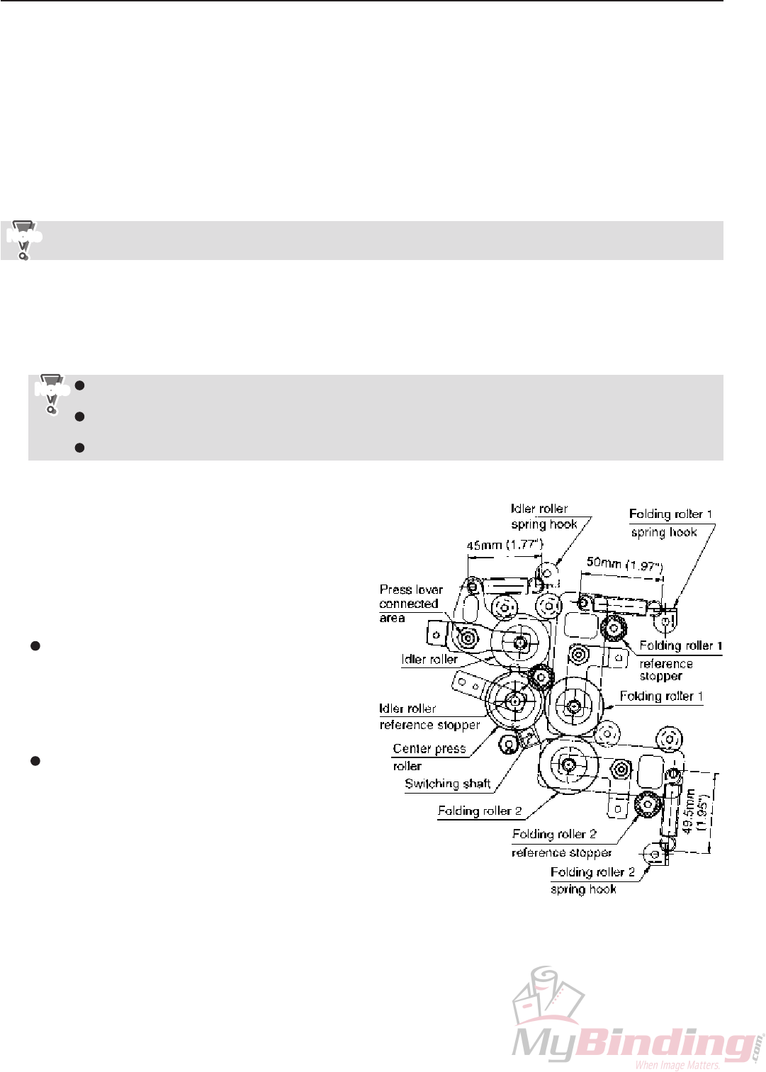
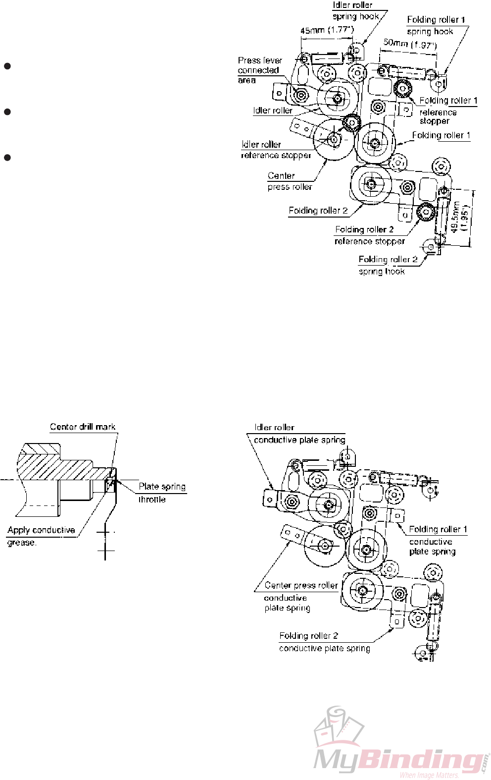
(6) Attaching the press spring T
qSecure the spring hook at the position shown in
the figure, and attach the press spring T.
(Primary adjustment in the assembly stage)
Spring T inner dimensions of idler roller:
45 mm (1.77")
(Spring pressure: 23.5 N ±8.5%)
Spring T inner dimensions of folding roller 1:
50 mm (1.97")
(Spring pressure: 38.8 N ±8.5%)
Spring T inner dimensions of folding roller 2:
49.5 mm (1.95")
(Spring pressure: 37.2 N ±8.5%)
wPerform test folding, and if wrinkles or extreme
folding misalignment along the sides of the paper
occur, check the balance between the left and
right pressure, and adjust by changing the spring
hooking direction. (Secondary adjustment by
passing paper)
(7) Attaching the plate spring (grounding conduction)
The plate spring helps static electricity accumulated in folding rollers to escape to the chassis.
qAttach so that the center drill mark of the folding roller edge and throttle of the plate spring contact.
Check that no anticorrosive coating is applied to the contact area of the folding roller edge.
wApply conductive grease to the plate spring. (Dow Corning MOLY KOTE 41)

1-10
12H-M12M0-0309-0
(8) Adjusting the tension of the paper ejection
drive timing belt
Inappropriate tension of the belt may cause such
problems as noise, slips, etc.
Using a tension gauge of 5 N (510 gf), apply
pressure of 3 N (306 gf) to the belt, and check
that the belt slacks by 3 to 5 mm (0.12" to 0.20").
(9) Adjusting the tension of the drive belt for the
jam correction knob
The jam correction knob rotates the folding rollers
during jam correction and cleaning of folding rollers
to facilitate work.
qCheck that when the jam correction knob is
rotated, the folding rollers rotate smoothly.
wUsing a tension gauge of 5 N (510 gf), apply
pressure of 3 N (306 gf) to the belt, and check
that the belt slacks by 3 to 5 mm (0.12" to 0.20").
(10) Attaching the main pulley of the center press
roller, and jam correction knob drive pulley of
the idler roller
qWhile pressing the main pulley against the frame
B side so that there is no thrust play of the helical
gear, attach it to the center press roller.
wWhile pressing the knob drive pulley against the
frame B side so that there is no thrust play of the
helical gear, attach it to the idler roller.
1-11
12H-M12M0-0309-0
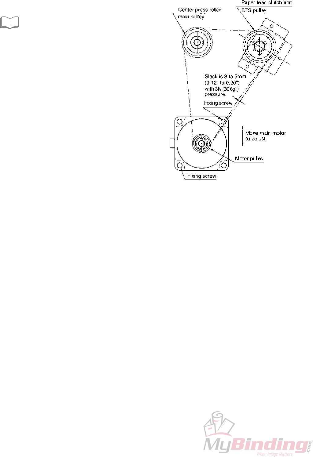
qSet the drive belt on the paper feed clutch unit, and
secure the bracket.
“2-1-6. Attaching the paper feed clutch unit”
wLoosen the two screws securing the main motor and
adjust the tension of the belt so that it slacks by 3 to 5
mm (0.12" to 0.20") when a pressure of 3 N (306 gf) is
applied to the belt using a 5 N (510 gf) tension gauge.
2-1-3. Adjusting the tension of the main drive timing belt
Inappropriate tension of the belt may cause such problems as noise, slips, etc.
eSee

1-12
12H-M12M0-0309-0
2-1-4. Paper ejection drive shaft
The stacker belt is driven at high speed intermittently using the electromagnetic clutch to enhance stacking
performance and processing speed.
Replace the paper ejection clutch using the following
procedure.
qCheck the accessories provided with the paper
ejection clutch unit.
Shim (adjusting washer, t = 0.1): 3
Collar: 1
wCheck for thrust play of the paper ejection drive shaft
at frame F side. At shipment, a shim (adjusting
washer) is inserted between the paper ejection drive
shaft and bearing to control thrust play to below 0.1
mm (0.004").
Check that thrust play is not minus (pressed state).
eWhile ensuring the w state, attach and secure the
clutch rotor at frame B side.
rAttach the collar, shim, armature (STS pulley)
provided with the paper ejection clutch unit as a set to
the drive shaft.
As the paper ejection clutch unit is adjusted
to an air gap (0.15 mm (0.006")) at shipment,
always attach the above parts to the
machine as a set.
Do not apply oil to the contacting area of the
clutch rotor and armature.
NoteNote
tUsing the shim provided, adjust so that thrust play of
the collar and E ring outside the armature becomes
less than 0.1 mm (0.004").
yCheck that the armature rotates smoothly.
Also check that paper ejection drive shaft does not
rotate when the armature rotates.
uApply a very small amount of oil to the area where the
drive shaft and bearing are connected.
(Orelube G90-140)
1-13
12H-M12M0-0309-0
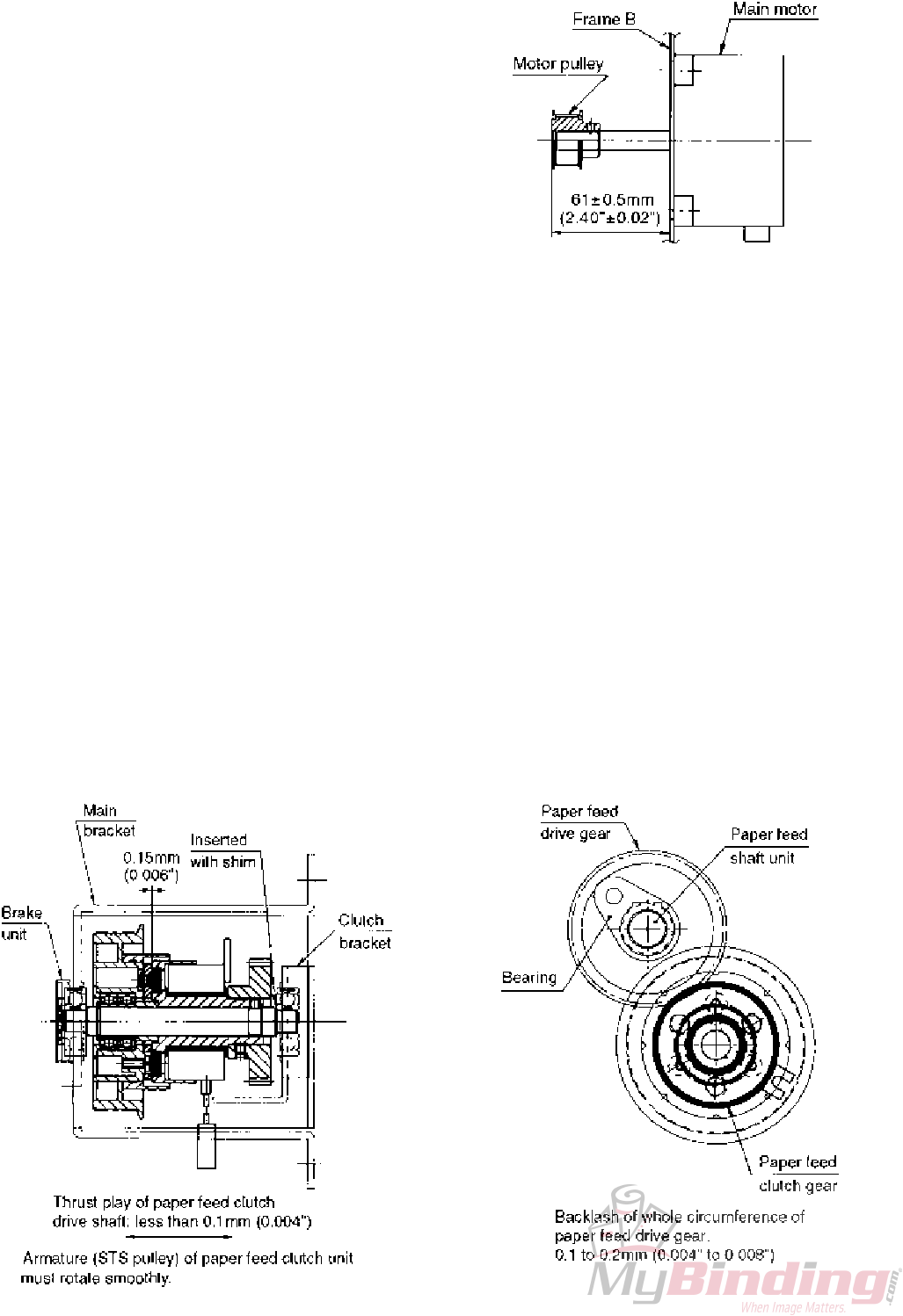
2-1-5. Attaching the motor pulley
If the motor pulley is not attached at the proper position, slipping of the drive belt and abnormal wear may result.
Replace the main motor using the following procedure.
qAttach the motor pulley to the main motor at the
position shown in the figure.
wAfter attaching, rotate the main motor and check that
the belt does not slip.
2-1-6. Attaching the paper feed clutch unit
With the DF-900 series, an electromagnetic clutch is used as a paper feed clutch to enhance processing speed and
stabilize paper feed performance.
Replace the paper feed clutch using the following procedure.
qCheck for thrust play of the paper feed clutch drive shaft at the clutch bracket side. At shipment, a shim (adjusting
washer) is inserted between the paper feed clutch drive shaft and bearing to control thrust play to below 0.1 mm
(0.004").
Check that thrust play is not minus (pressed state).
wWhile ensuring the q state, insert the bearing at the main bracket side, and secure the paper feed clutch unit.
eApply a very small amount of oil to the area where the drive shaft and bearing are connected. (Orelube G90-140)
rCheck that the paper feed drive gear (42T) and paper feed clutch gear (33T) are engaged appropriately along the
whole circumference (backlash: 0.1 to 0.2 mm (0.004" to 0.008")), and that they rotate smoothly.
Adjust the backlash by changing the clutch bracket position.
tApply grease to the whole circumference of the gear teeth. (Orelube G1650)

1-14
12H-M12M0-0309-0
2-1-7. Attaching the brake unit
The brake unit reduces inconsistency in the stopping position of the paper lead edge during paper feed, and stabilizes
the jam detection timing and number of sheets processed.
qTo prevent abnormal sounds due to the use of the
friction brake mechanism, apply a very small amount
of grease to the urethane area of the brake unit and
attach. (Orelube G1650)
wAfter attaching the brake unit, check that the rotating
torque of the paper feed shaft unit is 0.0147 to 0.0245
Nm (0.15 to 0.25 kgf • cm) with the paper separator
and paper feed ring not in contact.
However, even if the rotating torque does not meet
the above value, if the stopping position of the paper
lead edge is stable without touching the paper feed
inlet sensor it means that paper feed is stable and no
re-adjustments are required.
eApply a very small amount of oil to the area where the
paper feed shaft joint and bearing are connected.
(Orelube G90-140)

1-15
12H-M12M0-0309-0
2-2. Paper Feed Tray
As the paper feed tray mechanism is more or less the same as the DF-520N, only the differences are described in this
section.
2-2-1. Automatic paper size detection
Photosensors are located at the standard paper size positions. Paper size is detected when the shield attached to the
paper feed guide blocks a sensor.
For USA models, the auxiliary paper feed tray is also provided with a photosensor to differentiate between legal size
and letter size.
The automatic detection range is within ±7 mm (0.28") from standard paper size.
The paper feed guides move together left and right from the center of the paper feed tray.
Standard paper size which can be automatically detected
UK model : A3, B4, A4, B5, A5, B6 (6 types)
USA model: LGR, LGL, LTR, STMT, INV (5 types)
2-2-2. Paper size which can be stacked
Distance moved by paper feed guide: Maximum 310 mm (12.2")
: Minimum 76 mm (3.0")
Paper width which can be fed : Maximum 305 mm (12.0") ∗ 297 mm (11.7") in specifications: Width of A3 paper
: Minimum 76 mm (3.0") ∗ Width of B7 paper
Paper length which can be fed: Maximum 432 mm (17.0")
: Minimum 128 mm (5.1") ∗ Length of B7 paper
The above values are design specifications. In actual use, values given in instruction manual apply because they are
restricted by the length of the folding plate and paper receiving allowance of the paper ejection section.
Maximum paper size: 297 (width) × 432 (length) mm (11.7" × 17.0")
Minimum paper size : 128 (width) × 182 (length) mm (5.1" × 7.2")
∗B7 and A6 paper can be folded under certain conditions.

1-16
12H-M12M0-0309-0
2-2-3. Attaching the paper feed tray assembly
Take note when attaching the paper feed tray assembly because the direction of the set collar differs between the
DF-920 and DF-915 according to whether the paper feed tray up/down lever is provided or not.
Secure the set collar with some thrust play (0.1 to 0.2 mm (0.004" to 0.008")). Otherwise, load increases when the
paper feed tray rises, resulting in insufficient paper feed pressure even if the pressure is adjusted, and paper slips
occur easily.
Apply a very small amount of oil to the area where the fixed plate bearing and hinge rod are connected.
(Orelube G90-140)
Enlargement of section A
1-17
12H-M12M0-0309-0
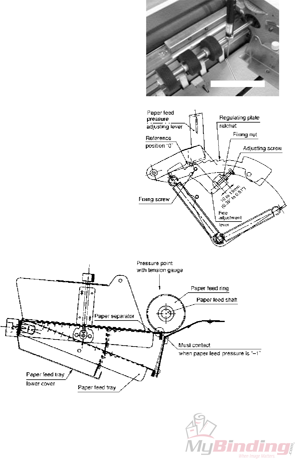
2-2-4. Adjusting the paper feed pressure
Adjust to the reference paper feed pressure to prevent double-feeding and slipping of paper.
qAttach the paper feed tray lower cover, raise the
paper feed tray, and set the paper feed pressure
adjusting lever to the reference position “0”.
wPress a 30 N (3.06 kgf) tension gauge against the
notch of the operating side of the paper feed tray, and
gradually increase the pressure until the paper feed
shaft and tension gauge contact.
Rotate the adjusting screw so that the tension gauge
value becomes 6 ± 0.18 N (612 ± 18 gf) in this state.
The clearance between the bracket and fine
adjustment lever should be around 10 to 13 mm
(0.39" to 0.51").
eAfter adjusting, tighten the fixing nut and fixing screw
to secure the fine adjustment lever.
rSet the paper feed pressure adjusting lever to “–1”.
Check that the paper feed tray can be pushed down
smoothly by hand, and check that when the paper
feed tray is raised gently, the paper separator at the
tip of the paper feed tray touches the paper feed ring.
tCheck that the paper feed tray moves up and down
smoothly.
yApply a very small amount of grease to the regulating
plate ratchet. (Orelube G1650)
Notch of paper feed tray

1-18
12H-M12M0-0309-0
2-2-5. Automatic up/down mechanism of paper feed tray (DF-920 only)
If this mechanism has been removed during motor replacement, attach it using the following procedure.
qAttach a pulley to the drive motor at the position
shown in the figure.
wApply a very small amount of thread locking to the set
screw. (Loctite 242: Medium strength/for screws)
eCheck for thrust play of the drive shaft assembly. At
shipment, a shim (adjusting washer) is inserted
between the collar and bearing (outer ring) at frame F
side to control thrust play to below 0.1 mm (0.004").
Check that thrust play is not minus (pressed state).
rWhile ensuring the e state, insert the bearing and
collar at the bracket side, and secure the bracket.
tApply a very small amount of oil to the area where the
drive shaft and bearing are connected.
(Orelube G90-140)
yAttach the plate and rack so that their surfaces touch
and slide.
uAdjust the points on the eccentric shaft and rack, and
secure temporarily. (Primary adjustment)
iMove the rack up and down, and check that there is
appropriate backlash (0.1 to 0.2 mm (0.004" to
0.008")) where the rack and gear engage, and the
rack moves smoothly. Do not tighten the set screw of
the gear just yet. Tighten after completing the
adjustment of “2-2-7”.
The rack fulcrum Z (0Z4-08022) is designated as a
semi-durable part. Replace it appropriately after
50000 times of up/down movements of the paper
feed tray.
oApply grease to the following parts. (Orelube G1650)
Contacting area between the up/down lever and
bearing outer ring
Connected area and sliding area of the eccentric
shaft and rack long hole
Connected area and sliding area of the Z part and
rack long hole
Sliding area of the plate and rack
Engaged area of the rack and gear

1-19
12H-M12M0-0309-0
2-2-6. Adjusting the tension of the paper feed tray automatic up/down drive timing belt
(DF-920 only)
If the tension of the belt is not appropriate, problems
such as faulty drive and jumping of the belt will occur.
Move the tension idler and adjust the tension of the
belt so that it slacks by 3 to 5 mm (0.12" to 0.20")
when a pressure of 3 N (306 gf) is applied to the belt
using a 5 N (510 gf) tension gauge.

1-20
12H-M12M0-0309-0
2-2-7. Adjusting the stopping position of the paper feed tray when rising/descending and paper
stacking amount
DF-920
To ensure paper stacking amount which can satisfy specifications, adjust the stopping position (motor drive range) of
the paper feed tray during automatic up/down.
Perform adjustments as follows without the paper feed tray automatic up/down drive gear of section “2-2-5” secured.
qMove the switch bracket for the length of the long
hole and adjust so that when the up/down lever is
pressed down to the lower limit, the actuator of the
lower limit detection microswitch turns ON the switch,
and a clearance of 0.7 ± 0.1 mm (0.028" ± 0.004") is
formed at the position shown in the figure.
wMove the switch bracket for the length of the long
hole and adjust so that when the up/down lever is
pressed up to the upper limit, the actuator of the
upper limit detection microswitch turns ON the switch,
and a clearance of 0.8 ± 0.1 mm (0.031" ± 0.004") is
formed at the position shown in the figure.
eTighten the set screw of the drive gear D cut, and
lower the paper feed tray to the lower limit position
from the control panel.
rRotate the eccentric shaft and adjust so that the
paper feed tray stops at a depth of 45 ± 1 mm (1.77" ±
0.04") from the bent part of the lower paper feed inlet.
The paper stacking amount given in specifications is
500 sheets (approximately 44 mm (1.73")) for fine
quality paper 64 g/m2 (16 lb).
When the paper feed tray descends
When the paper feed tray rises

1-21
12H-M12M0-0309-0
tAfter adjusting the paper stacking amount, raise and lower the paper feed tray from the control panel, and check the
following.
To raise the paper feed tray from the control panel, press the “+” key of the folding plate 1 folding stopper adjusting
key while pressing the stop key.
To lower the paper feed tray, press the “–” key of the folding plate 1 folding stopper adjusting key while pressing the
stop key.
The paper feed tray can also be raised and lowered using the maintenance mode “Code No.24: Paper feed tray up/
down motor test”.
“3. MAINTENANCE MODE” in CHAPTER 2 ELECTRICAL COMPONENTS
eSee
When the paper feed tray descends
The actuator of the lower limit detection
microswitch should not be pressing the switch
completely, and no load should be applied on Z at
the rack long hole upper edge from overrun of the
drive motor.
(When load is applied to Z, the slack of the
opposite tension idler side of the drive belt
changes.)
The paper feed tray stops at the specified position
of the paper stacking amount (approximately 44
mm (1.73")).
When the paper feed tray rises
When the paper feed pressure setting is “–1”, the paper separator at the tip of the paper feed tray touches the
paper feed ring to maintain appropriate paper feed pressure.
The actuator of the upper limit detection microswitch must not be pressing the switch completely, and there
should be a clearance between the rack long hole lower edge and Z.
When the paper feed pressure setting is “6”, there should be a clearance between the up/down lever and bearing
outer ring so that the paper feed pressure set is not affected.
When the paper feed tray descends
When the paper feed tray rises

1-22
12H-M12M0-0309-0
ySecure the set screw of the drive gear, and apply a
very small amount of thread locking to the set screw.
(Loctite 242: Medium strength)
DF-915
Adjust the paper feed tray stopping position so that the paper stacking amount satisfies the specifications, and the
position of the tray is detected accurately when the tray is raised/lowered manually.
qMove the roller unit of the hinge lever up and down and adjust so that when the paper feed tray up/down lever is
raised and the paper feed tray is lowered, the hinge lever touches the stopper, and the paper feed tray stops at a
depth of 45 ± 1 mm (1.77" ± 0.04") from the bent part of the lower paper feed inlet.
The paper stacking amount given in specifications is 500 sheets (approximately 44 mm (1.73")) for fine quality
paper 64 g/m2 (16 lb).
When the paper feed tray rises
When the paper feed tray descends
wMove the switch angle and adjust so that when the
paper feed tray up/down lever is lowered and the
paper feed tray is raised, the actuator of the
microswitch turns ON the switch and a clearance of
0.5 to 0.7 mm (0.02" to 0.03") is formed at the position
shown in the figure.
eAfter completing the adjustment in w, check that the
R hinge of the actuator and the actuator press of the
paper feed tray up/down lever do not press the
actuator by continuous point contact and cause
damage.
The switch angle is provided with a stopper to prevent
damage of the switch by the damage of the actuator.
1-23
12H-M12M0-0309-0
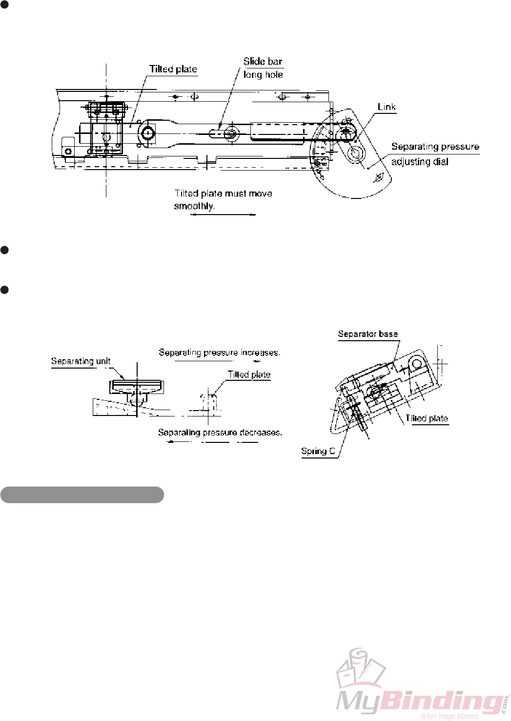
2-3. Separating Mechanism
The separating mechanism is more or less the same as the DF-520N.
The separating pressure can be set in seven steps from 0 to 6 to handle special coated paper. For this reason, the
separator base is located on the tilted plate to which it is connected by the link mechanism. When the separating
pressure adjusting dial is rotated, the tilted plate moves and forced pressure is applied to the separator base.
When the separating pressure scale value is standard “0”, the forced pressure is released, and only pressure of
spring C (approximately 120 g) is applied to the separator base.
When the separating pressure adjusting dial is rotated, forced pressure is applied to the separator base if the scale
value is within 3.5 (design value is 2.5).
Setting the separating pressure
When using normal paper, set the separating pressure to standard “0”, and increase 0.5 at a time if double-feed
occurs. For coated paper, set the separating pressure to “2.5 to 3.5”. However, first set to “2.5” and increase 0.5 at a
time if double-feed occurs.
Using at a high separating pressure from the beginning causes problems such as paper jam at the separator and
abnormal wear of the paper feed ring.

1-24
12H-M12M0-0309-0
2-4. Paper Feed Inlet
The following changes have been made in the paper feed inlet mechanism from the DF-520N.
The curvature of the rib shape has been changed so that paper is fed properly to the very last sheet even in multiple
paper feed (500 sheets) of small size paper (B6, INV, etc.) by automatic rise/descent of the paper feed tray.
To enhance the processing speed, a transmissive sensor (paper feed inlet sensor) is provided at the paper feed
inlet.
By changing the delay time based on the paper feed inlet sensor for all paper sizes and folding modes, paper can
be fed at the optimum paper feed timing.
To eliminate static electricity, a static eliminator brush is provided at the paper feed inlet sensor (light-receiving).
2-4-1. Replacing the paper feed inlet unit
When replacing the paper feed inlet unit, take note of the following points.
After replacing the paper feed inlet sensor, check that one sheet of 52.4 g/m2 (14 lb) paper is detected properly.
The static eliminator brush is made of carbon fiber with high non-contact static elimination effects. When replacing
the static eliminator brush, attach it at the position shown in the figure so that it does not touch the center press
roller.
1-25
12H-M12M0-0309-0
2-4-2. Cleaning the paper feed inlet sensor
The paper feed inlet sensor will not function if adhered with printing powder and paper dust, and an error message will
be displayed.
The LCD of the DF-920 displays “JAM FEED SECT” while the right window of the DF-915 displays “J1-2”.
When these messages appear, clean the sensor.
qRemove the two fixing screws, and remove the
sensor cover attached to the paper feed inlet upper
guide.
Sensor cover
Fixing screws
wUse a cloth or cotton swab to remove powder or paper dust adhered to the paper feed inlet sensor (light-emitting).
eRemove the paper feed inlet sensor (light-emitting), insert a cotton swab into the hole to remove powder or paper
dust adhered to the paper feed inlet sensor (light-receiving).
If the sensor is very dirty, remove the paper feed inlet upper guide to clean.
NoteNote
rReinstall the paper feed inlet sensor (light-emitting) and sensor cover back to their original positions.
Be sure to perform this cleaning together with the “2-5-6. Cleaning the paper ejection outlet sensor” described
later as a set when visiting users for maintenance work.
NoteNote
2-4-3. Providing instructions on cleaning the paper feed inlet sensor to users
“21. CLEANING THE UNIT” in the instruction manual (chapter 20 in the case of the DF-915) describes the method
of cleaning using an Air Duster (a commercially available air spray for eliminating dust). Explain the details carefully to
users and instruct them on use.
With this method, the nozzle of the Air Duster is inserted into the hole of the sensor cover and paper feed inlet and
sprayed briefly.
Hole of sensor cover Paper feed inlet
1-26
12H-M12M0-0309-0
2-5. Paper Ejection Mechanism
To enhance paper ejection stack performance and processing speed, the paper ejection drive mechanism is
intermittently driven by the electromagnetic clutch. To improve operability, the movement of the stacker roller has
been made automatic.
2-5-1. Replacing the stacker belt
Take note of the following points when replacing the belt.
Belt front/back : The green side is the front.
Rotating direction of the belt: The rotating direction is indicated by an arrow on the belt back (black side).
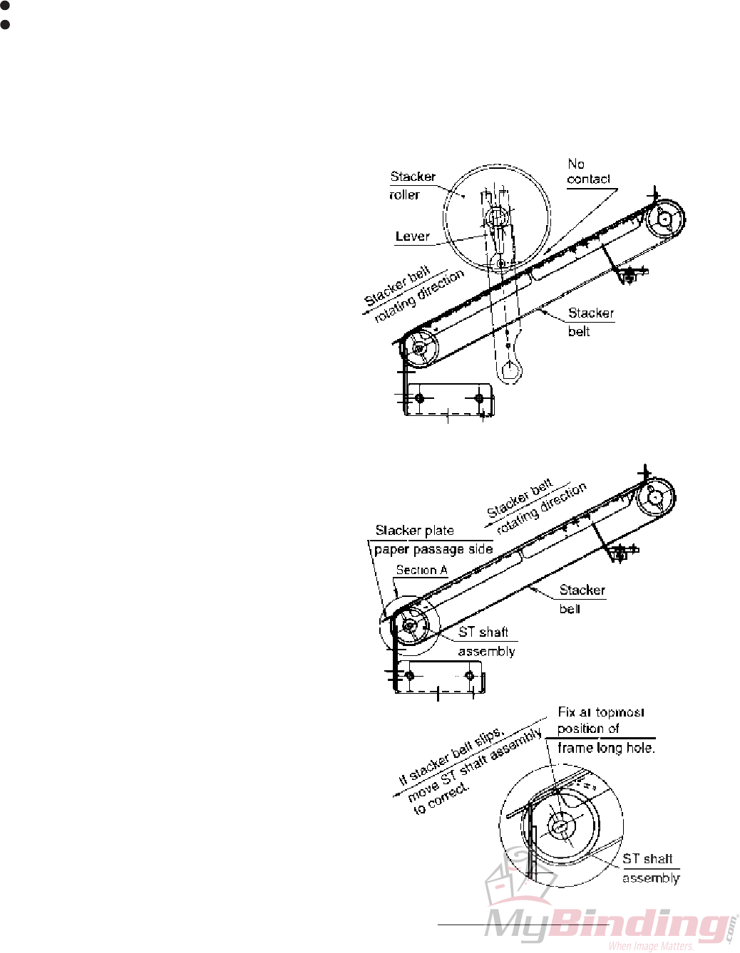
2-5-2. Adjusting the tension of the stacker belt
Perform the following check and adjustment if the stacker belt slips while rotating.
Normally, the belt slips due to the change in the frictional coefficient between the stacker plate and belt back from the
load of the stacker roller.
qIf the belt slips with the stacker roller and belt not
contacting (the stacker roller is raised), perform step
w.
If the belt does not slip in this state, perform step e.
wGenerally, the ST shaft assembly is fixed at the
topmost position of the frame long hole. This state is
the recommended stretch rate of the belt. (Stretch
rate: 4%)
If the belt slips, loosen the screw fixing the ST shaft
assembly, and adjust the tension of the belt by
moving the assembly.
The adjusting range is within 2 mm (0.08").
eThe area where the stacker plate and belt back
contact each other is pasted with a Teflon tape to
reduce the frictional coefficient. The belt may start to
slip when the effects of the tape drop. In such cases,
paste a new tape.
(NITTO DENKO NITOFLON tape No.973UL t0.13 ×
W15)
Enlargement of section A
1-27
12H-M12M0-0309-0
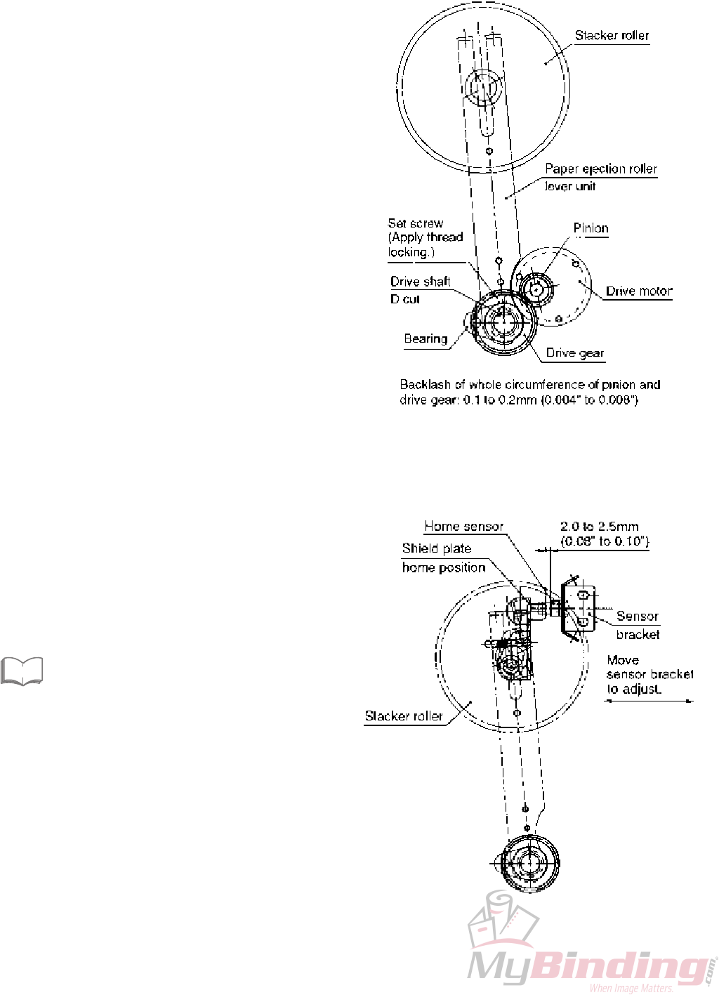
2-5-3. Paper ejection roller lever unit
The basic configuration of this unit is more or less the same as the DF-520N.
If the paper ejection roller lever unit has been removed during the replacement of the drive motor, attach it using the
following procedure.
qApply a very small amount of oil to the area where the
drive shaft of the paper ejection roller lever unit and
bearing are connected. (Orelube G90-140)
wCheck that there is appropriate backlash (0.1 to 0.2
mm (0.004" to 0.008")) at the area where the drive
gear of the paper ejection roller lever unit and pinion
are engaged, and that they rotate smoothly.
eApply grease to the engaged gear teeth.
(Orelube G1650)
rSecure the set screw of the drive gear, and apply a
very small amount of thread locking to the set screw.
(Loctite 242: Medium strength)
2-5-4. Adjusting and checking the stacker roller home sensor
The stopping position of the stacker roller moves automatically in six steps according to the folded paper length.
The moving distance is controlled by the moving duration from the home sensor.
qWhen the switch lever is at the home position, secure
the sensor bracket with a clearance of 2.0 to 2.5 mm
(0.08" to 0.10") between the switch lever shield and
home sensor.
wAfter adjusting, check that the home sensor turns ON
and OFF properly in the maintenance mode.
“3. MAINTENANCE MODE” in CHAPTER 2
ELECTRICAL COMPONENTS
eSee
1-28
12H-M12M0-0309-0
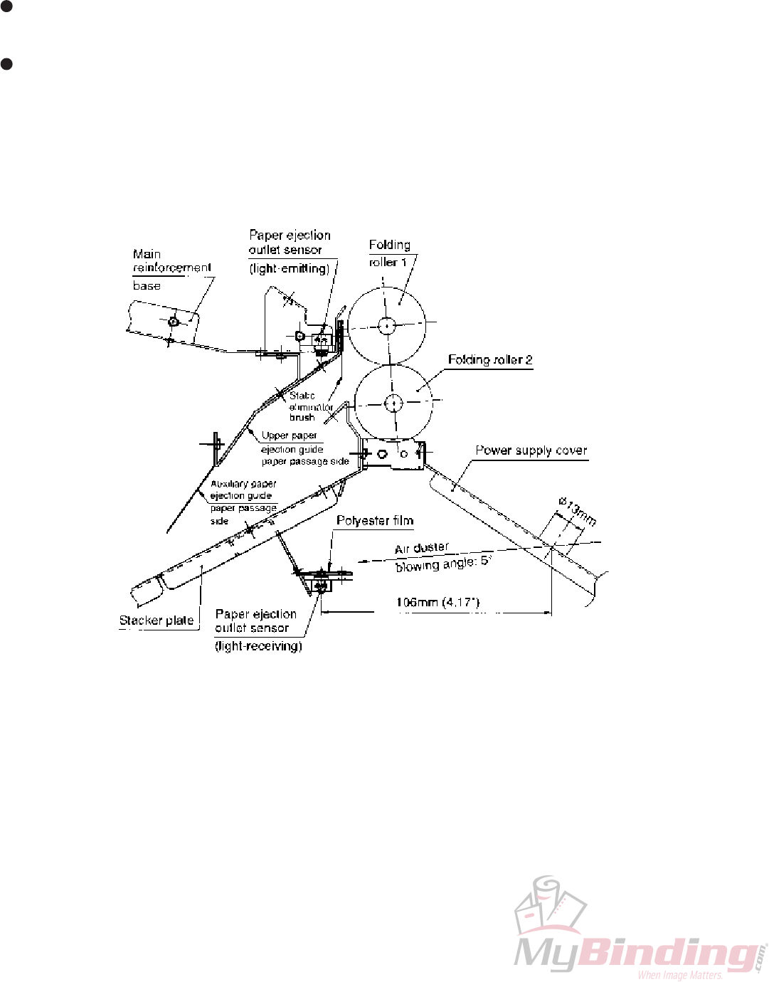
2-5-5. Replacing the paper ejection outlet sensor
To detect jams in the paper ejection section, a transmissive sensor (paper ejection outlet sensor) is provided at the
main reinforcement base and stacker plate. To eliminate static electricity of the paper ejected, a static eliminator brush
(stainless fiber) is provided on the upper paper ejection guide.
Take note of the following points when replacing the paper ejection outlet sensor.
After replacing the paper ejection outlet sensor, check that one sheet of 52.4 g/m2 (14 lb) paper is detected
properly.
To prevent accumulation of paper dust on the sensor surface, the paper ejection outlet sensor (light-receiving)
protection cover is pasted with a polyester film.
2-5-6. Cleaning the paper ejection outlet sensor
The power supply cover has a φ13 mm hole to simplify cleaning of accumulated paper dust, etc. by blowing an Air
Duster (a commercially available air spray for eliminating dust) from this hole. Remove folding plate 2, insert the spray
nozzle facing down at 5° into the cover hole and blow air.
1-29
12H-M12M0-0309-0
2-6. Folding Plates
As the folding plate mechanism is more or less the same as the DF-520N, only important differences are described in
this section.
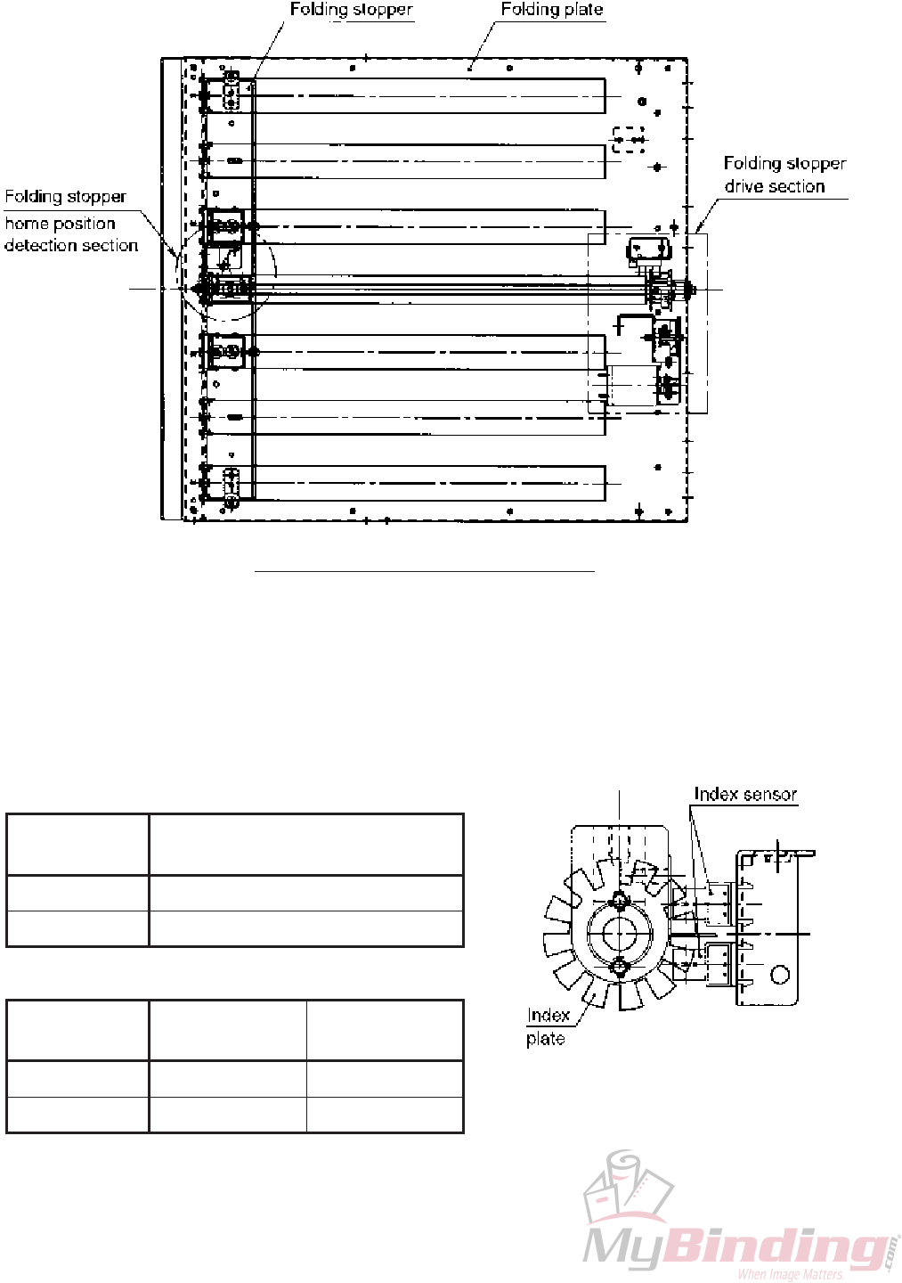
Overall view of folding plate mechanism
(1) Movement control of folding stopper
A slit plate (index plate) divided into 12 parts (pulses) is mounted to a screw shaft with a pitch of 1.5 mm (0.06").
The number of slits (pulses) is counted by two photointerrupters (index sensor) to control the moving distance
and direction of the folding stopper.
The minimum distance moved by the stopper is 0.125 mm (0.005") of one pulse of the above index plate.
The restricted value of each folding plate is shown below.
Limitations of length of folded plane
Maximum distance moved by
folding stopper from home position
Folding plate 1 288.5 mm (11.36")
Folding plate 2 180.5 mm (7.11")
Maximum folded
plane length
Folding plate 1 325 mm (12.79") 42 mm (1.65")
Folding plate 2 217 mm (8.54") 47 mm (1.85")
Minimum folded
plane length
Moving distance of folding stopper

1-30
12H-M12M0-0309-0
(3) Shape of paper inlet of folding plate
The lower guide of folding plate 1 is tapered to facilitate entrance and exit of paper to and from the folding roller.
The upper guide of folding plate 2 is extruded (deep drawing) to reduce the local clearance of the conveyance
route in the aim to reduce W dent and dog ears.
(2) Adjusting the home position of the folding
stopper
The home position of the folding stopper is the
basic position where the shield plate blocks the
home sensor added with the correction value set in
the following maintenance mode.
“3. MAINTENANCE MODE” in CHAPTER 2
ELECTRICAL COMPONENTS
Correction value of folding plate 1 home position
(Maintenance mode code No.1)
Correction value of folding plate 2 home position
(Maintenance mode code No.2)
Correction value of switching shaft home
position (Maintenance mode code No.3)
See
Folding plate 1 Folding plate 2
1-31
12H-M12M0-0309-0
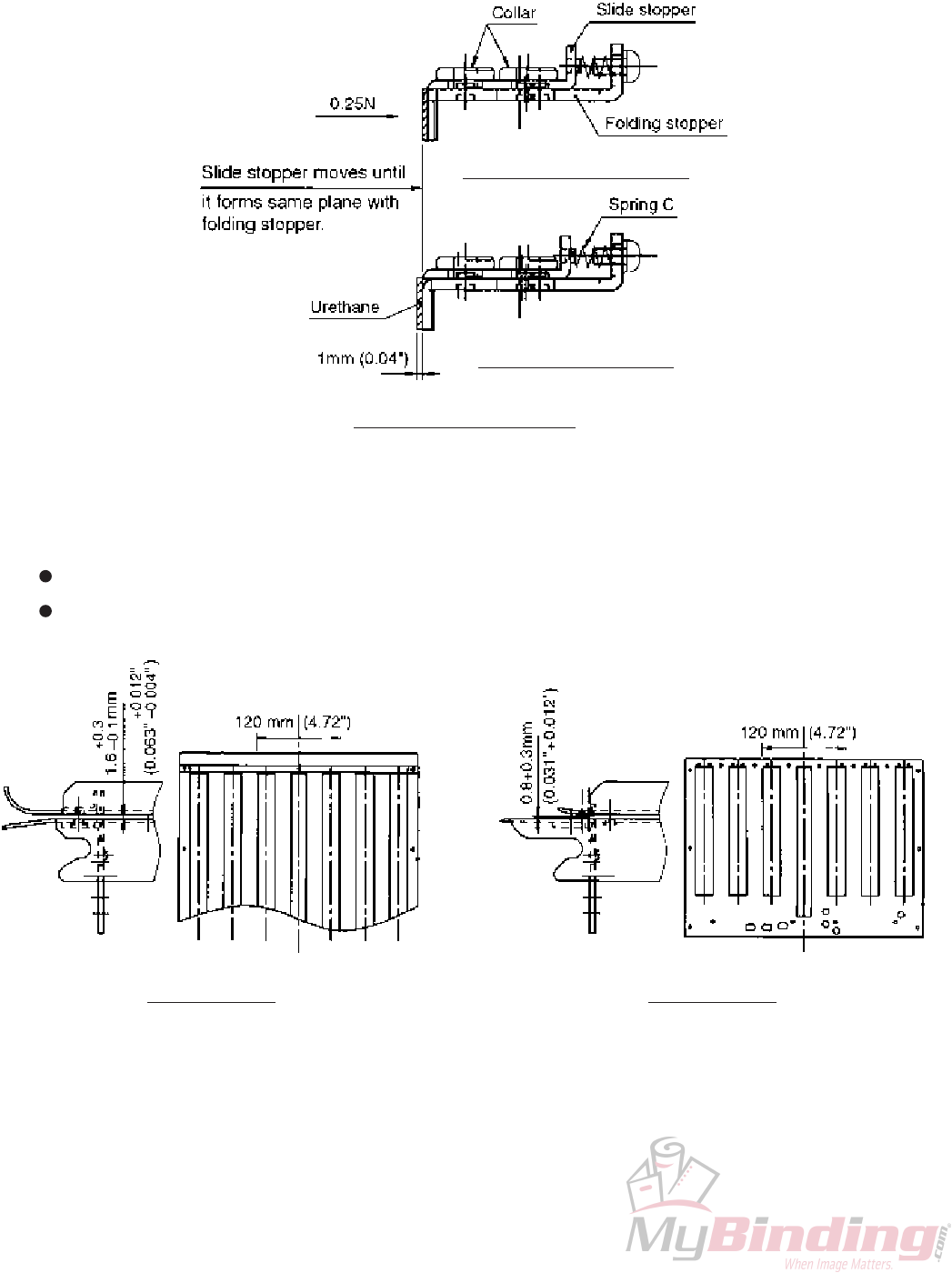
(4) Structure of folding stopper
To reduce the collision sound when the lead edge of the paper collides with the folding stopper, a double-stopper
structure where a slide stopper is mounted onto the folding stopper is provided.
The side of the slide stopper which collides with the paper is also pasted with urethane to simultaneously reduce
the collision sound and paper bending.
Folding stopper structure
2-6-1. Adjusting the clearance of the conveyance route of the folding plate
To prevent paper jamming at the folding plate, check that the clearance of the conveyance route of the folding plate
satisfies the following values within the 120 mm (4.72") range from the center of the folding plate.
Folding plate 1: 1.6 mm (0.063" )
Folding plate 2: 0.8 + 0.3 mm (0.031" + 0.012")
Folding plate 1
+0.3
–0.1
Bottom regulated position
Top regulated position
Folding plate 2
+0.012"
–0.004"

1-32
12H-M12M0-0309-0
2-6-2. Checking and adjusting the thrust play of the screw shaft unit
Check the following points when folding misalignment along the vertical length of the paper and folding plate motor
lock occurs.
Check that a shim is inserted between the chassis and bearing at the folding plate motor side so that the thrust play
of the screw shaft unit becomes 0.1 to less than 0.15 mm (0.004" to less than 0.006"), and that the unit moves lightly
and smoothly.
Apply a very small amount of oil to the area where the screw shaft and bearing are connected. (Orelube G90-140)
To prevent folding plate motor lock, never apply oil or grease to the sliding area where the screw shaft, full nut, and
guide block bush are connected.
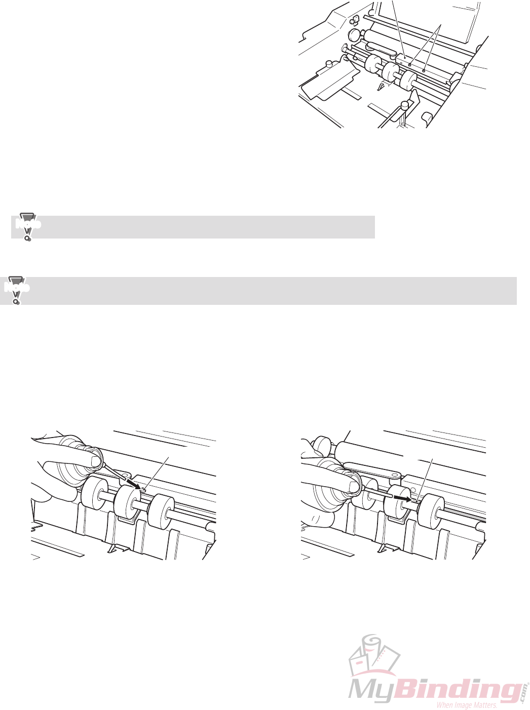
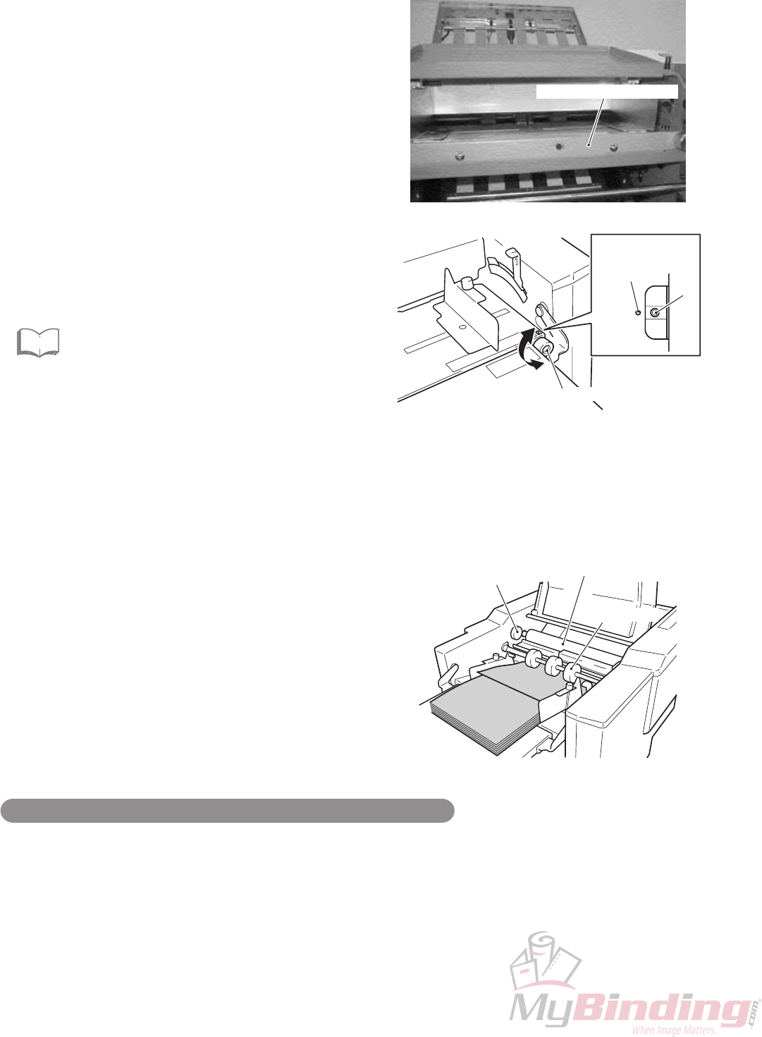
2-6-3. Replacing the full nut
If the female screw of the full nut (resin) wears due to extended use, thrust play between the screw shaft and full nut
increases, resulting in reduced folding stopper stop accuracy and increased folding misalignment along the vertical
length of the paper due to play of the folding stopper itself.
When these problems occur, replace the full nut.
The full nut cannot be replaced by merely pulling it upwards because the screw is cut on the whole block
circumference for higher durability. Rotate the screw shaft as shown in the figure, move in the right direction, and pull
the full nut downwards.

1-33
12H-M12M0-0309-0
2-6-4. Motor deceleration pulley assembly
If the tension of the belt is not appropriate, problems such as folding plate motor lock and jumping of the belt occur.
qTighten the set screw with a torque of 0.69 Nm (7.0
kgf • cm), and secure the motor pulley at the position
shown in the figure.
wCheck that a shim is inserted between the idler pulley
and E ring so that the thrust play becomes 0.1 to 0.3
mm (0.004" to 0.012").
eApply a very small amount of oil to the area where the
idler pulley and fulcrum pillar are connected.
(Orelube G90-140)
rApply a pressure of 3 N (306 gf) to deceleration
timing belt 1 using a tension gauge of 5 N (510 gf),
and check that the belt slacks by 2 to 3 mm (0.08" to
0.12").
tApply a pressure of 3 N (306 gf) to deceleration
timing belt 2 using a tension gauge of 5 N (510 gf),
then move the motor deceleration pulley assembly
and adjust the tension of the belt so that it slacks by 2
to 3 mm (0.08" to 0.12").

1-34
12H-M12M0-0309-0
2-6-5. Adjusting the position of the folding stopper and slide stopper
qTighten the M3 screw with a torque of 0.64 Nm (6.5 kgf • cm) and secure the collar.
wCheck that when a pressure of 0.25 N (25 gf) is applied to the slide stopper using a tension gauge of 1 N (102 gf),
the slide stopper moves smoothly to the bottom regulated position, and when the tension gauge is removed, it
returns promptly to the top regulated position.
The distance moved by the slide stopper is 1 mm (0.04").
eApply a very small amount of thread locking to the collar fixing screw from the back of the folding stopper.
(Three Bond 1401B: For preventing loosening)
Top regulated position
2-6-6. Folding stopper slide pin
A slide pin is provided at both ends of the folding stopper
so that the folding stopper moves horizontally, thus
preventing abnormal low speed movements due to load
changes and abnormal noise.
qCheck that the two photointerrupters are attached
parallel to each other.
wWhen the screw shaft is rotated by hand, check that
the two sensors turn ON and OFF properly in the
maintenance mode.
“3. MAINTENANCE MODE” in CHAPTER 2
ELECTRICAL COMPONENTS
eCheck that the folding stopper moves away from the
home position when the “+” key of the folding stopper
adjusting key on the control panel is pressed, and
towards the home position when the “–” key is
pressed.
eSee
2-6-7. Checking the operations of the index sensor
Bottom regulated position

1-35
12H-M12M0-0309-0
Check that the home sensor turns ON and OFF properly
in the maintenance mode.
“3. MAINTENANCE MODE” in CHAPTER 2
ELECTRICAL COMPONENTS
eSee
2-6-9. Fixed position of the switching adjusting plate of folding plate 2 folding stopper
Adjusting plate for setting the switching shaft to the regulated stopping position in single folding.
qSecure the switching adjusting plate at the position (7.0 mm (0.28")) shown in the figure while paying attention to
the left and right parallelity.
wApply a very small amount of thread locking to the fixing screw of the switching adjusting plate.
(Loctite 242: Medium strength)
2-6-8. Checking the operations of the home sensor
1-36
12H-M12M0-0309-0
2-6-10. Adjusting the parallelity of the folding stoppers
Adjust the parallelity of the lead edge of paper fed and folding stoppers of folding plates 1 and 2 to reduce folding
misalignment along the sides of the paper.
qRemove the paper feed tray lower cover, and adjust
the skew correction knob of the paper feed tray to the
standard position.
Adjust both the paper feed pressure and paper
separating pressure to “0” on the scale.
wStack well aligned 80 g/m2 (20 lb) fine quality paper
(vertical grain) on the paper feed tray, adjust the
paper feed guides to the paper width properly, and
secure them.
If the paper feed guides are not adjusted to the paper
width, folding misalignment along the sides of the
paper occurs.
eSelect “Code No.28: Folding stopper parallelity
mode” of the maintenance mode, and press the start
key.
“3. MAINTENANCE MODE” in CHAPTER 2
ELECTRICAL COMPONENTS
For DF-920, selecting this mode and pressing the
start key causes the paper feed tray to rise
automatically, and the folding stoppers of folding
plates 1 and 2 move to the set position.
For DF-915, selecting this mode and pressing the
start key after lowering the paper feed tray up/down
lever and raising the paper feed tray moves the
folding stoppers to the set position.
eSee
Skew correction knob
Pin
<Standard
position>
Round hole
Idler roller
Jam correction knob
Paper feed ring
rRotate the paper feed ring by hand, and feed the lead
edge of the paper to the idler roller.
tRotate the jam correction knob, and move the lead
edge of the paper near the slide stopper of folding
plate 1.
Paper feed tray lower cover
Adjusting method when the folding mode is set to brochure fold
When adjusting the parallelity of the folding stoppers, there is a need to move the folding stoppers away from the
home position. When the folding mode is set to brochure fold, as the folding stoppers are set away from the home
position, parallelity deviation can be seen more clearly.
Set the folding mode to brochure fold after step w, and proceed to step e.

1-37
12H-M12M0-0309-0
yLoosen the fixing screws of the folding stopper, and
adjust so that the folding stopper becomes parallel to
the lead edge of the paper, and then tighten the fixing
screws.
uIf paper slips during conveyance in t, check the left
and right roller nips of the idler roller.
“2-1-2. (4) Attaching the drive gear (helical
gear) of folding roller”
eSee
iRotate the jam correction knob, and move the lead
edge of the paper near the slide stopper of folding
plate 2.
oLoosen the fixing screws of the folding stopper, and
adjust so that the folding stopper becomes parallel to
the lead edge of the paper, and then tighten the fixing
screws.
Enlargement of section A
Enlargement of section B
Section A
Fixing screws Folding stopper
Slide stoppers
Fixing screws
Folding stopper
Slide stoppers
Section B

1-38
12H-M12M0-0309-0
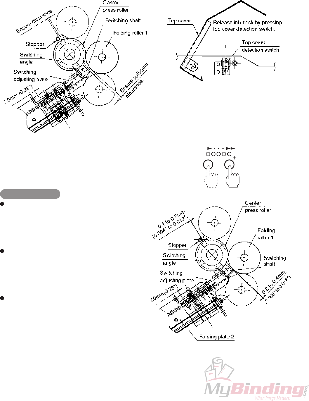
2-6-11. Adjusting the home position of the switching shaft (stopping position) in single folding
The switching shaft switches the paper conveyance route between single folding and other folding modes.
To adjust the home position of the switching shaft, adjust the clearance between folding roller 1 and tip of the
switching shaft to 0.2 to 0.4 mm (0.008" to 0.016") when the folding stopper of folding plate 2 is stopping at the
home position.
If this adjustment is not carried out appropriately, problems may occur in folding which may cause conveyed paper
to become thick such as the single folding of thick paper and cross folding. These problems include flattening of the
lead edge of folded paper and paper jam at the folding roller.
In the single folding of thin paper, one folding wrinkle line occurs near the 15 mm (0.59") position from the folded
line.
The correction value of the switching shaft home position adjustment in the maintenance mode does not affect the
folding size.
Enlargement of section A
1-39
12H-M12M0-0309-0
qFor DF-920, select “Code No.3: Switching shaft home position adjustment” of the maintenance mode with all
interlock switches (top cover, side cover, folding plate 1, folding plate 2 detection switches) and paper ejection
cover detection sensor ON.
For DF-915, select “Code No.3: Switching shaft home position adjustment” of the maintenance mode with all
interlock switches (top cover, folding plate 1, folding plate 2 detection switches) ON.
“3. MAINTENANCE MODE” in CHAPTER 2 ELECTRICAL COMPONENTS
eSee
1-40
12H-M12M0-0309-0
wPressing the clear key while pressing the stop key initializes the folding stopper, and moves the folding stopper of
folding plate 2 to the home position.
eOpen the top cover (leave the detection switch ON), and check that there is clearance between the protrusion of the
switching angle and stopper (M4).
If there is no clearance, it means that the switching adjusting plate is pushing the switching shaft excessively, and
this may cause the urethane sheet of the switching shaft to peel off or motor lock.
rWith the top cover opened (detection switch in the
ON state), press the speed key and adjust the
clearance between the protrusion of the switching
angle at the left and right frames and stopper (M4) to
0.1 to 0.3 mm (0.004" to 0.012").
Adjusting method
Pressing the “+” speed key increases the correction
value by 1, and moves the folding stopper of folding
plate 2 by 0.125 mm (0.005") in the opposite
direction of the home position.
(The clearance between folding roller 1 and
switching shaft tip widens.)
Pressing the “–” speed key decreases the
correction value by 1, and moves the folding
stopper of folding plate 2 by 0.125 mm (0.005") in
the direction of the home position.
(The clearance between folding roller 1 and
switching shaft tip becomes smaller.)
The settable correction values range from “–20” to
“+5”. The position of the folding stopper ranges
from –2.5 to +0.625 mm (–0.10" to +0.02") with the
home position as 0 mm (0").
tAfter adjusting the clearance, single fold thick and
thin paper, and check for problems of the folded line.
If the clearance is too narrow, paper jams during
single folding of thick paper, resulting in scratches
and wrinkles near the folded line.
If the clearance is too broad, one folding wrinkle line
occurs near the 15 mm (0.59") position from the
folded line during single folding of thin paper.
1-41
12H-M12M0-0309-0
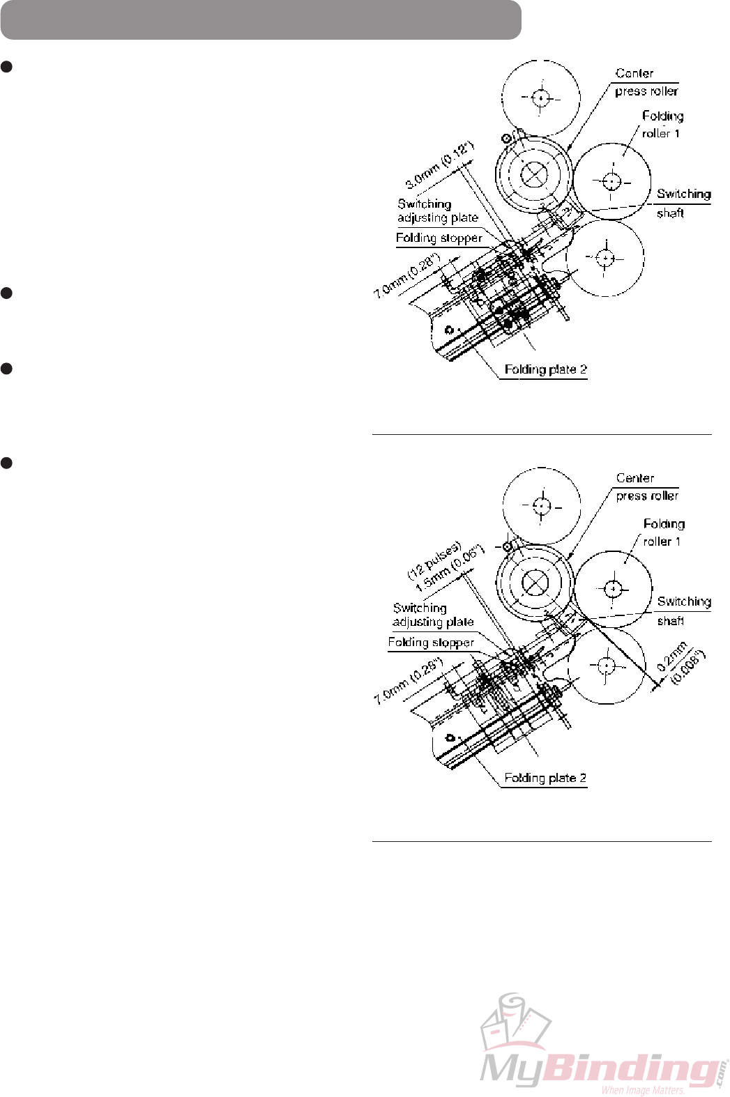
Relation between home position of switching shaft (stopping position) and
stopping position of folding stopper (Reference)
Both folding plates 1 and 2 in electrical design
(theory) are set so that the clearance between the tip
of the folding stopper and folding plate chassis
becomes 3.0 mm (0.12") when the shield blocks the
home sensor.
In mechanical design, this clearance is set to 1.5 mm
(0.06") (–12 pulses).
This is to easily make the inconsistencies of the home
position (stopping position) of the switching shaft
occurring due to the accumulation of parts tolerance
even by electrical correction.
When the folding stopper is stopping at the reference
position, the reference dimensions of the switching
adjusting plate is 7.0 mm (0.28").
When the folding stopper and switching adjusting
plate are stopping at their reference positions, the
reference dimensions of the switching shaft stopping
position is 0.2 mm (0.008").
When the switching shaft stopping position is the
reference dimension, the correction value of the
switching shaft home position is “–12”.
Switching shaft home position (stopping position)
in electrical design (Theory)
Switching shaft home position (stopping position)
in mechanical design
1-42
12H-M12M0-0309-0
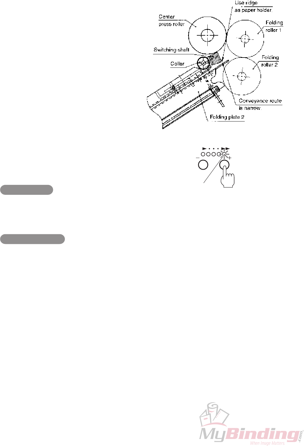
2-6-12. Stopping position of switching shaft in folding modes other than single folding
The stopping position of the switching shaft in folding
modes other than single folding is set near the folding
roller so that the collar for reducing defects such as
double dent and dog ears of brochure folding serves as
the stopper of the switching shaft. As a result, the ridge
of the switching shaft is used as the holder of the paper
ejected from folding plate 2.
At this time, as the conveyance route for paper coming
into folding plate 2 becomes narrow, defects such as
flattening of the first folded line may occur in the double
folding of some thick paper (157 g/m2 (40 lb)).
Perform the following solutions for such defects.
(1) Setting the thick paper mode (Can be
performed by users.)
Increase the rotational speed of the folding roller
temporarily.
Setting method
Press the “+” speed key and set the maximum
processing speed, and press it again for another
two seconds. The maximum speed lamp blinks,
indicating that the thick paper mode has been set.
Clearing the setting
Press the “–” speed key. The maximum speed lamp
stops blinking and lights up, indicating that the thick
paper mode has been cleared.
This setting will also be cleared when the power is
turned off.
Blinking (Thick paper mode)

1-43
12H-M12M0-0309-0
(2) Removing the stopper (collar) of the switching shaft (Can not be performed by users.)
If the defects in (1) thick paper mode cannot be corrected, or when use of brochure folding is minimum, remove
the switching shaft stopper (collar).
qRemove folding plate 2 from the unit.
wRemove the resin collar (white) from inside the frame (two on the left and right of the switching shaft).
eTighten the screw of the resin collar from outside the frame.
As the diameter of the stopper of the switching shaft changes from φ12 mm to φ4 mm, the stopping position of the
switching shaft moves back, the conveyance route broadens, allowing thick paper to enter folding plate 2.
Stopping position of switching shaft
in standard use (with φ12 mm collar) Stopping position of switching shaft
when φ12 mm collar is removed

1-44
12H-M12M0-0309-0
2-6-13. Switching shaft cushion (urethane sheet)
To reduce noise during single folding, a cushion (urethane sheet) is attached to the switching shaft so that the
switching shaft and switching adjusting plate do not touch.
Cleaning the urethane sheet surface with alcohol during cleaning of the folding rollers increases the frictional
coefficient of the urethane surface excessively to exceed the allowed torque of the folding stopper drive motor in some
rare cases. As a result, folding plate 2 may motor lock during initialization (returning of folding stopper to home
position) immediately after power ON.
For this reason, do not clean the urethane sheet surface of the switching shaft with alcohol.
When folding plate 2 motor locks
Wipe the cushion (urethane sheet) surface of the switching shaft with a cloth moistened with grease or oil
(Orelube G90-140), then wipe immediately with a clean dry cloth to reduce the frictional coefficient of the urethane
surface. If no grease or oil is available, move the hand across the urethane surface once.

1-45
12H-M12M0-0309-0
2-6-14. Adjusting folded size
When performing folding operations under the following conditions, adjust so that the folded size becomes the
specified value when folded using the folding stoppers of folding plates 1 and 2. Adjust the folded size after completing
all other adjustments.
Paper conveyance conditions in adjustment of folded size are described below.
Paper : A4 (Letter) 80 g/m2 (20 lb) fine quality paper (vertical grain)
Folding mode : Letter fold Processing speed : Level 5 (MAX)
Paper feed pressure: 0 (Standard) Paper separating pressure: 0 (Standard)
Skew correction : 0 (Standard) Folding stopper : Parallel
The standard folded sizes under the above conditions are shown in the figure.
∗ ( ) shows the folded size for letter size paper.
Folded size by folding plate 1
199 mm (7.37")
Measuring point
(Center)
99 mm
(3.67")
98 mm
(3.63")
Folded size by folding plate 2
100 mm (3.70")
Paper feed direction
(1) Adjusting folded size by folding plate 1
For DF-920
qTurn on the power while pressing both the start and stop keys to enter the maintenance mode.
“3. MAINTENANCE MODE” in CHAPTER 2 ELECTRICAL COMPONENTS
eSee
ePress the clear key while pressing the stop key to initialize the folding stopper of folding plate 1.
rPress the test key to perform test folding.
tMeasure the folded size of the second sheet ejected, and enter the adjustment value using the “+” or “–” key of
the speed key so that this folded size becomes the specified value.
Each time the “+” key is pressed, the folded size increases by 0.125 mm (0.005").
Each time the “–” key is pressed, the folded size decreases by 0.125 mm (0.005").
The settable adjustment values range from “–20” to “+20”. The folded size ranges from –2.5 to +2.5 mm
(–0.10" to +0.10").
yAfter setting, check the finish again by test folding.
uRepeat the above procedure until the folded size becomes the specified value.
wSelect “Code No.1: STOP1 DEFAULT”, check
the default adjustment value displayed on the
LCD and note it down.
1.STOP1 DEFAULT
∗∗∗
Adjustment value

1-46
12H-M12M0-0309-0
For DF-915
qTurn on the power while pressing both the start and stop keys to enter the maintenance mode.
“3. MAINTENANCE MODE” in CHAPTER 2 ELECTRICAL COMPONENTS
wSelect “Code No.1: Folding plate 1 home position adjustment”, check the default adjustment value displayed
on the right 7-segment window and note it down.
ePress the clear key while pressing the stop key to initialize the folding stopper of folding plate 1.
rPress the test key to perform test folding.
tMeasure the folded size of the second sheet ejected, and enter the adjustment value using the “+” or “–” key of
the speed key so that this folded size becomes the specified value.
Each time the “+” key is pressed, the folded size increases by 0.125 mm (0.005").
Each time the “–” key is pressed, the folded size decreases by 0.125 mm (0.005").
The settable adjustment values range from “–20” to “+20”. The folded size ranges from –2.5 to +2.5 mm
(–0.10" to +0.10").
yAfter setting, check the finish again by test folding.
uRepeat the above procedure until the folded size becomes the specified value.
(2) Adjusting folded size by folding plate 2
For DF-920
qTurn on the power while pressing both the start and stop keys to enter the maintenance mode.
eSee
wSelect “Code No.2: STOP2 DEFAULT”, check
the default adjustment value displayed on the
LCD and note it down.
2.STOP2 DEFAULT
∗∗∗
Adjustment value
eThe following procedure is the same as “(1) Adjusting folded size by folding plate 1”.
For DF-915
qTurn on the power while pressing both the start and stop keys to enter the maintenance mode.
wSelect “Code No.2: Folding plate 2 home position adjustment”, check the default adjustment value displayed
on the right 7-segment window and note it down.
eThe following procedure is the same as “(1) Adjusting folded size by folding plate 1”.

1-47
12H-M12M0-0309-0
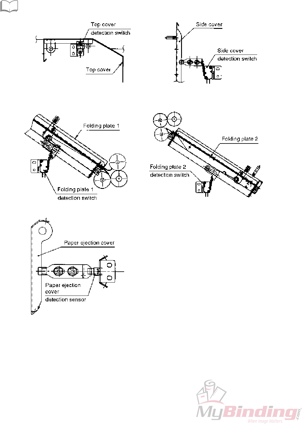
qOpen and close the top cover and check that it is
moderately tight and remains open without falling
from its weight at an open/close angle of 60°.
wMove the switch bracket for the length of the long
hole and adjust so that when the top cover is closed,
the actuator of the microswitch turns ON the switch,
and a clearance of 1.0 ± 0.2 mm (0.039" ± 0.008")
forms at the position shown in the figure.
eAfter adjustment, check that the detection switch is
able to detect the open/close of the top cover in the
maintenance mode.
“3. MAINTENANCE MODE” in CHAPTER 2
ELECTRICAL COMPONENTS
2-7. Exterior and Detection Switches
2-7-1. Adjusting the top cover and detection switch (interlock)
eSee
2-7-2. Adjusting the side cover and detection switch (interlock) (DF-920 only)
qOpen and close the side cover and check that it is
moderately tight.
wIf abnormal sounds are produced (as if the cushion is
being rubbed) when the side cover is opened and
closed, apply a very small amount of oil to the frame
of the cushion contact, and wipe away immediately
with a dry cloth.
eMove the switch bracket for the length of the long
hole and adjust so that when the side cover is closed,
the actuator of the microswitch turns ON the switch,
and a clearance of 1.0 ± 0.2 mm (0.039" ± 0.008")
forms at the position shown in the figure.
rAfter adjustment, check that the detection switch is
able to detect the open/close of the side cover in the
maintenance mode.
“3. MAINTENANCE MODE” in CHAPTER 2
ELECTRICAL COMPONENTS
tMove and adjust the catch bracket so that the side
cover is suctioned and maintained by the magnet
catcher at the stopping position of the stopper.
eSee

1-48
12H-M12M0-0309-0
2-7-3. Adjusting folding plate 1 and detection switch (interlock)
2-7-4. Adjusting folding plate 2 and detection switch (interlock)
qMove the switch bracket for the length of the long hole and adjust so that when folding plate 2 is attached to the unit
at the reference position (position of mark “1 ( )” on the label), the actuator of the microswitch turns ON the switch
according to the displacement of the detection lever, and a clearance of 0.7 to 0.9 mm (0.03" to 0.04") forms at the
position shown in the figure.
wCheck that when folding plate 2 is moved to the drop prevention position (position of mark “2 ( )” on the label), the
microswitch goes OFF.
eAfter adjustment, check that the detection switch is able to detect that folding plate 2 has been attached to the unit
in the maintenance mode.
“3. MAINTENANCE MODE” in CHAPTER 2 ELECTRICAL COMPONENTS
qMove the switch bracket for the length of the long
hole and adjust so that when folding plate 1 is
attached to the unit, the actuator of the microswitch
turns ON the switch according to the displacement of
the detection lever, and a clearance of 0.5 to 0.7 mm
(0.02" to 0.03") forms at the position shown in the
figure.
wAfter adjustment, check that the detection switch is
able to detect that folding plate 1 has been attached
to the unit in the maintenance mode.
“3. MAINTENANCE MODE” in CHAPTER 2
ELECTRICAL COMPONENTS
eSee
eSee
Folding plate 2 reference position Folding plate 2 drop prevention position
1-49
12H-M12M0-0309-0
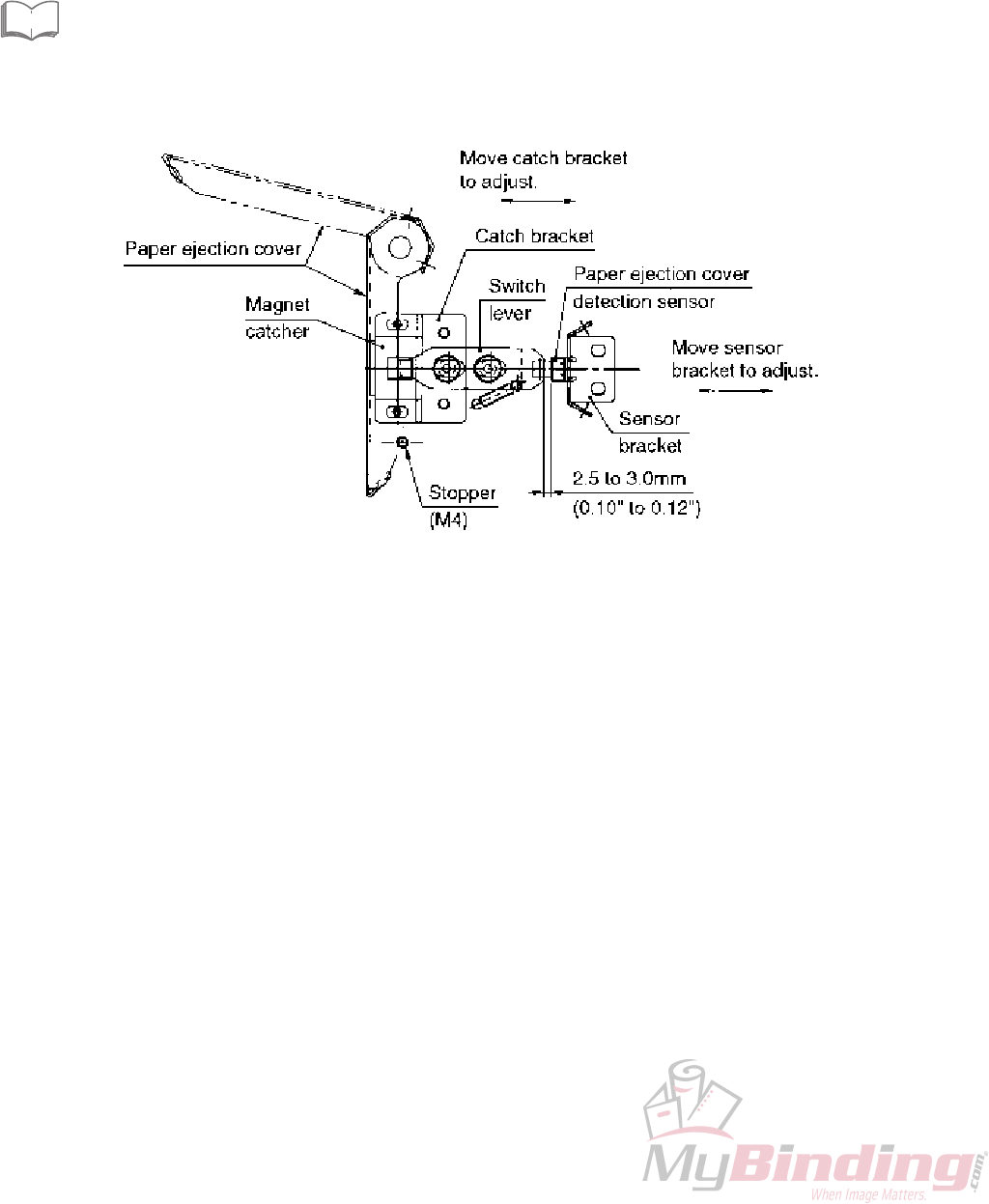
2-7-5. Adjusting the paper ejection cover and detection sensor (DF-920 only)
qOpen and close the paper ejection cover and check that it is moderately tight.
wIf abnormal sounds are produced (as if the cushion is being rubbed) when the paper ejection cover is opened and
closed, apply a very small amount of oil to the frame of the cushion contact, and wipe away immediately with a dry
cloth.
eMove and adjust the sensor bracket so that when the paper ejection cover is closed, the clearance between the
switch lever shield and paper ejection cover detection sensor becomes 2.5 to 3.0 mm (0.10" to 0.12").
rAfter adjustment, check that the detection sensor is able to detect the open/close of the paper ejection cover in the
maintenance mode.
“3. MAINTENANCE MODE” in CHAPTER 2 ELECTRICAL COMPONENTS
tMove and adjust the catch bracket so that the paper ejection cover is suctioned and maintained by the magnet
catcher at the stopping position of the stopper.
eSee

1-50
12H-M12M0-0309-0
3. PERIODIC INSPECTIONS
3-1. Inspection Points and Procedure
In order to maintain stable paper folding performance and quality, perform periodic inspection every time the machine
has processed 200,000 sheets or every six months, whichever is faster.
Inspection point Inspection Procedure
Paper feed ring,
paper separator
Folding roller
Stacker roller moving
mechanism
Jam correction knob
Paper feed tray automatic up/
down mechanism
Paper feed inlet,
paper ejection outlet sensors
Folding stopper
Folding plate screw shaft
Cleaning
Cleaning
Oiling
Oiling
Greasing,
inspection
Cleaning
Inspection
Cleaning, oiling
Remove paper dust, and clean with alcohol.
Remove paper dust, and clean with alcohol.
Apply oil the sintered bearing.
Apply oil the sintered bearing.
Apply grease the gear surface and rack. (DF-920 only)
Check the wear state of the Z collar.
“2-4-2. Cleaning the paper feed inlet sensor”
“2-5-6. Cleaning the paper ejection outlet
sensor”
Check that the fixing screw of the Z collar of the slide
stopper is not loose.
Remove paper dust near the female screw groove on
the screw shaft and the home sensor, and apply a small
amount of oil to the bearing.
The area where the screw shaft and the full nut are
connected cannot be applied with oil or grease.
3-2. Other General Precautions
3-2-1. Oiling
Apply the specified oil to the following locations.
Area where shaft and bearing are connected (sintered bearing)
Specified oil: Orelube G90-140 (Equivalent to ISO #460)
Make sure no oil adhered to the contact surfaces of the armature and rotor of the electromagnetic clutch,
and area where the screw shaft and full nut are connected.
NoteNote
3-2-2. Greasing
Apply the specified grease to the following parts.
Gear teeth, paper feed tray automatic up/down drive rack related parts, etc.
Specified grease: Orelube G1650 (Equivalent to NLGI #1)
Plate spring for grounding conduction of folding roller
Specified grease: Dow Corning MOLY KOTE 41 (Conductive grease)
Make sure no grease adhered to the contact surfaces of the armature and rotor of the electromagnetic
clutch, and area where the screw shaft and full nut are connected.
NoteNote
eSee

1-51
12H-M12M0-0309-0
3-2-3. Preventing screws from loosening
If the following screws have been removed, apply a very small amount of the specified thread locking.
Set screw of drive gear for automatic up/down of paper feed tray
Set screw of drive gear for stacker roller
Fixing screw of folding pate 2 switching adjusting plate
Specified thread locking: Loctite 242 (Medium strength/for screws)
Fixing screw of slide stopper Z collar
Specified thread locking: Three Bond 1401B (For preventing loosening)
3-2-4. Others
Make sure that no oil and grease adheres to the timing belt and drive pulley grooves.
Fill maintenance data (folded size correction data, etc.) changed during machine adjustments in the backup data
form pasted to the back of the main cover F.

1-52
12H-M12M0-0309-0
4. TROUBLESHOOTING GUIDE (MECHANICAL CAUSES)
4-1. When Paper is Conveyed Skewed
Cause Solution
The left and right nip amount
differs between the folding rollers.
The thrust play of the folding roller
drive gear is large.
The press pressure of the folding
roller is not balanced between the
left and right sides.
The folding roller is deformed.
Check the attached state of the reference stopper, and make the roller nip
the same.
“2-1-2. (3) Attaching the reference stoppers”
“2-1-2. (4) Attaching the drive gear (helical gear) of folding roller”
Adjust so that there is no thrust play.
“2-1-2. (4) Attaching the drive gear (helical gear) of folding roller”
Adjust the press pressure.
“2-1-2. (6) Attaching the press spring T”
Replace the folding roller.
“2-1-2. Replacing folding rollers”
Cause Solution
The press pressure of the folding
roller is strong.
The folding roller is deformed.
Adjust the press pressure.
Especially set the press pressure of folding roller 1 weak. (About 45 to 46 mm
(1.77" to 1.81"))
“2-1-2. (6) Attaching the press spring T”
Replace the folding roller.
“2-1-2. Replacing folding rollers”
Cause Solution
The plate spring for grounding
conduction has worn out. Apply conductive grease or replace the plate spring.
“2-1-2. (7) Attaching the plate spring (grounding conduction)”
Cause Solution
The thrust play of the paper
ejection drive shaft and paper
ejection clutch is not appropriate.
Adjust so that the thrust play is less than 0.1 mm (0.004").
“2-1-4. Paper ejection drive shaft”
eSee
eSee
eSee
eSee
4-2. When Paper Wrinkles
eSee
eSee
4-3. When Abnormal Sounds (Metal Sliding Sounds) are Produced During
Rotation of Folding Rollers
eSee
4-4. When Stacker Belt Rotates Heavily
eSee

1-53
12H-M12M0-0309-0
4-5. Stopping Position of Paper Lead Edge Does Not Stabilize During Paper Feed,
and Paper Jams Near Paper Feed Inlet Sensor
Cause Solution
As the rotating load is too light
during paper feed drive, paper
continuous-feeds.
Wipe off a small amount of grease from the brake unit of the paper feed
clutch to decrease the amount.
If the brake unit has worn out, replace it.
“2-1-7. Attaching the brake unit”
4-6. When Paper Slips Frequently
Cause Solution
Contact resistance occurs when
the paper feed tray rises, and the
reference paper feed pressure is
insufficient.
The paper feed pressure
adjustment is inappropriate.
The up/down lever and bearing are
touching, and the reference paper
feed pressure is insufficient.
(DF-920 only)
When attaching the paper feed tray to the unit, ensure that thrust play is
appropriate.
“2-2-3. Attaching the paper feed tray assembly”
Re-adjust the reference paper feed pressure.
“2-2-4. Adjusting the paper feed pressure”
Adjust the microswitch detection position when the paper feed tray rises.
“2-2-7. Adjusting the stopping position of the paper feed tray
when rising/descending and paper stacking amount”
4-7. When Continuous-feed Occurs Frequently with Small Paper (B7, INV, etc.)
Cause Solution
The processing speed is too fast or
the paper feed pressure is too
high.
Set the processing speed to less than “4” and the paper feed pressure to “0”
or “–1”.
4-8. When Stacker Belt Slips
Cause Solution
The tension of the stacker belt is
too weak, or tension differs
between the left and right sides.
The Teflon tape on the stacker
plate has worn out.
Adjust the tension of the stacker belt.
“2-5-2. Adjusting the tension of the stacker belt”
Replace the Teflon tape.
“2-5-2. Adjusting the tension of the stacker belt”
4-9. When Folding Stopper Moves Abnormally Slow
Cause Solution
No thrust play of the screw shaft
unit.
The tension of the drive belt of the
screw shaft is too strong.
Adjust so that the thrust play becomes 0.1 to less than 0.15 mm (0.004" to
less than 0.006").
“2-6-2. Checking and adjusting the thrust play of the screw shaft
unit”
Adjust so that the belt slacks by the specified amount.
“2-6-4. Motor deceleration pulley assembly”
eSee
eSee
eSee
eSee
eSee
eSee
eSee
eSee

1-54
12H-M12M0-0309-0
4-10. When Folding Misalignment Along Vertical Length of Paper is Large
Cause Solution
Thrust play of the screw shaft unit
is large.
The full nut has worn out, and the
thrust play of the area connected
the screw shaft is large.
Adjust so that the thrust play becomes 0.1 to less than 0.15 mm (0.004" to
less than 0.006").
“2-6-2. Checking and adjusting the thrust play of the screw shaft
unit”
Replace the full nut.
“2-6-3. Replacing the full nut”
4-11. When Folding Misalignment Along Sides of Paper is Large
Cause Solution
Paper is conveyed skewed.
Paper lead edge and folding
stopper are not parallel.
Perform “4-1. When Paper is Conveyed Skewed”.
Adjust the parallelity of the folding stopper.
“2-6-10. Adjusting the parallelity of the folding stoppers”
4-12. Paper Jams at Folding Unit or Flattening of Folded Line Occurs During
Single Folding and When Thick Paper is Used, or Folding Wrinkle Line is
Formed at Folded Line with Thin Paper
Cause Solution
The clearance between the folding
roller and switching shaft is too
large.
Adjust the clearance.
“2-6-11. Adjusting the home position of the switching shaft
(stopping position) in single folding”
4-13. Paper Jams at Folding Unit or Flattening of Folded Line Occurs During
Folding Modes Other Than Single Folding and When Thick Paper is Used
Cause Solution
As the conveyance route is too
narrow, the thick paper does not
enter the folding rollers easily.
Increase the processing speed.
“2-6-12. (1) Setting the thick paper mode”
Change the stopping position of the switching shaft, and widen the
conveyance route.
“2-6-12. (2) Removing the stopper (collar) of the switching shaft”
4-14. When Motor Lock of Folding Plate 2 Occurs
Cause Solution
The frictional coefficient of the
cushion (urethane sheet) surface
of the switching shaft is high,
exceeding the allowed current
during motor drive.
Decrease the frictional coefficient.
“2-6-13. Switching shaft cushion (urethane sheet)”
eSee
eSee
eSee
eSee
eSee
eSee
eSee

2-1
12H-M12M0-0309-0
CHAPTER 2
ELECTRICAL COMPONENTS
1. Block Diagram of Structure and Outline of
Each Block......................................................2-2
1-1. MC Unit ................................................... 2-6
1-2. Control Panel ..........................................2-6
1-3. Paper Feed Inlet Sensor ......................... 2-6
1-4. Paper Ejection Outlet Sensor ................. 2-6
1-5. Paper Switch........................................... 2-6
1-6. Top Cover Switch ................................... 2-6
1-7. Side Cover Switch (DF-920 only) ........... 2-7
1-8. Paper Ejection Cover Sensor
(DF-920 only) .......................................... 2-7
1-9. Paper Feed Tray Upper Limit Detection
Switch (DF-920 only) .............................. 2-7
1-10. Paper Feed Tray Lower Limit Detection
Switch (DF-920 only) .............................. 2-7
1-11. Folding Plate 1 Set Switch ...................... 2-7
1-12. Folding Plate 2 Set Switch ...................... 2-7
1-13. Folding Plate 1 Index Sensor A/B ........... 2-7
1-14. Folding Plate 2 Index Sensor A/B ........... 2-7
1-15. Folding Plate 1 Home Sensor ................. 2-8
1-16. Folding Plate 2 Home Sensor ................. 2-8
1-17. Main Motor .............................................. 2-8
1-18. Paper Feed Tray Up/Down Motor
(DF-920 only) .......................................... 2-8
1-19. Folding Plate 1 Motor.............................. 2-8
1-20. Folding Plate 2 Motor.............................. 2-8
1-21. Stacker Roller Moving Motor .................. 2-8
1-22. Stacker Roller Home Sensor .................. 2-8
1-23. Paper Feed Clutch .................................. 2-8
1-24. Paper Ejection Clutch ............................. 2-9
1-25. Main Motor Index Sensor........................ 2-9
1-26. PS P.W.B. Unit ....................................... 2-9
1-27. Paper Feed Tray Set Switch
(DF-915 only) .......................................... 2-9
1-28. Switching Power Supply ......................... 2-9
1-29. Power Switch .......................................... 2-9
1-30. Power Inlet .............................................. 2-9
1-31. Power Cord ............................................. 2-9
2. Errors and Causes .........................................2-10
2-1. When Paper Jams Occur........................2-10
2-2. Troubleshooting ...................................... 2-10
2-3. Other Condition Messages ..................... 2-12
2-4. Emergency Measures When the Paper
Switch Damages ..................................... 2-14
3. Maintenance Mode ......................................... 2-15
3-1. Entering the Maintenance Mode ............. 2-15
3-2. Setting the Maintenance Mode ............... 2-15
3-3. List of Maintenance Modes ..................... 2-16
3-4. Precautions for Setting Folding Stopper
Fixed Mode (DF-920 only) ......................2-27
4. Backup Data Form ......................................... 2-28
5. Initializing the Memory .................................. 2-30
6. Precautions on Replacing the MC Unit ........ 2-31
7. Upgrading the Program Version...................2-32
8. Overall Schematic Diagram (DF-920) ........... 2-33
9. Overall Schematic Diagram (DF-915) ........... 2-34
10. Wiring Diagram 1/2 (DF-920) ......................... 2-35
11. Wiring Diagram 2/2 (DF-920) ......................... 2-36
12. Wiring Diagram 1/2 (DF-915) ......................... 2-37
13. Wiring Diagram 2/2 (DF-915) ......................... 2-38

2-2
12H-M12M0-0309-0
1. BLOCK DIAGRAM OF STRUCTURE AND OUTLINE OF EACH BLOCK
DF-920 block diagram
1-1. MC unit
1-17. Main motor
1-2. Control panel
1-22. Stacker roller home sensor
1-18. Paper feed tray up/down motor
1-9. Paper feed tray upper limit
detection switch
1-10. Paper feed tray lower limit
detection switch
Legal paper detection sensor
(USA model only)
1-26. PS P.W.B. unit
1-23. Paper feed clutch
1-24. Paper ejection clutch
1-3. Paper feed inlet sensor
1-4. Paper ejection outlet sensor
1-5. Paper switch
1-6. Top cover switch
1-7. Side cover switch
1-8. Paper ejection cover sensor
1-11. Folding plate 1 set switch
1-19. Folding plate 1 motor
1-13. Folding plate 1 index sensor A
1-13. Folding plate 1 index sensor B
1-15. Folding plate 1 home sensor
1-12. Folding plate 2 set switch
1-20. Folding plate 2 motor
1-14. Folding plate 2 index sensor A
1-14. Folding plate 2 index sensor B
1-16. Folding plate 2 home sensor
1-28. Switching power supply
1-25. Main motor index sensor
1-21. Stacker roller moving motor
1-29. Power switch
: Primary cable
1-30. Power inlet
1-31. Power cord
: Secondary cable

2-3
12H-M12M0-0309-0
1-9
1-2
1-22
1-7
1-29 1-10 1-1
1-8 1-11 1-6 1-23
1-24 1-12 1-30
1-19 1-13
1-15
1-20 1-14
1-16
1-21 1-4 1-26
1-17 1-28 1-18
1-3
1-5
1-26
(USA model only)
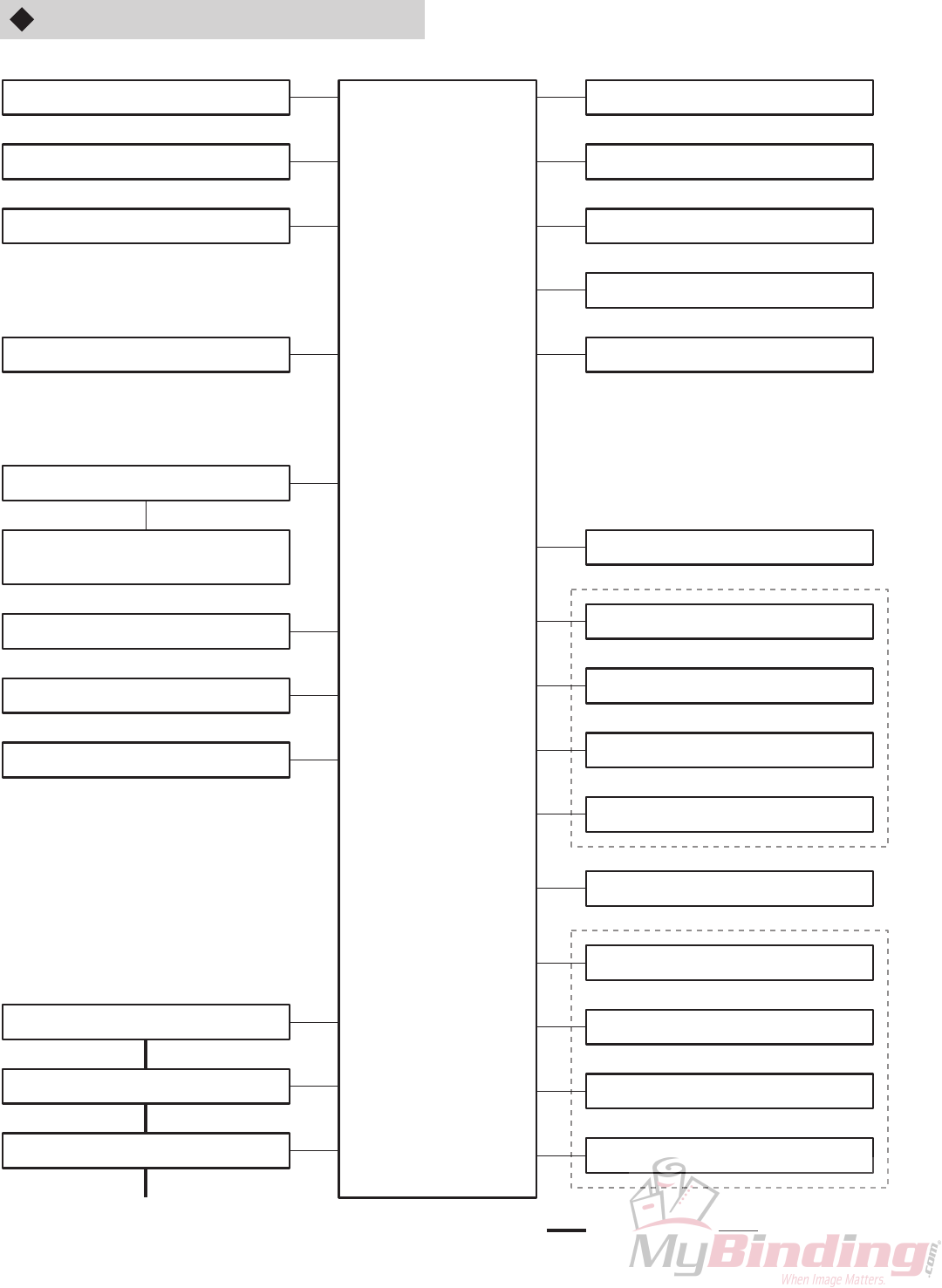
2-4
12H-M12M0-0309-0
DF-915 block diagram
1-1. MC unit
1-17. Main motor
1-2. Control panel
1-22. Stacker roller home sensor
1-27. Paper feed tray set switch
Legal paper detection sensor
(USA model only)
1-26. PS P.W.B. unit
1-23. Paper feed clutch
1-24. Paper ejection clutch
1-3. Paper feed inlet sensor
1-4. Paper ejection outlet sensor
1-5. Paper switch
1-6. Top cover switch
1-11. Folding plate 1 set switch
1-19. Folding plate 1 motor
1-13. Folding plate 1 index sensor A
1-13. Folding plate 1 index sensor B
1-15. Folding plate 1 home sensor
1-12. Folding plate 2 set switch
1-20. Folding plate 2 motor
1-14. Folding plate 2 index sensor A
1-14. Folding plate 2 index sensor B
1-16. Folding plate 2 home sensor
1-28. Switching power supply
1-25. Main motor index sensor
1-21. Stacker roller moving motor
1-29. Power switch
: Primary cable
1-30. Power inlet
1-31. Power cord
: Secondary cable

2-5
12H-M12M0-0309-0
1-2
1-29 1-1
1-27
1-22
1-11 1-6
1-23
1-12 1-30
1-21 1-4 1-26
1-17 1-28
1-19 1-13
1-15
1-20 1-14
1-16
1-3
1-5
1-26
(USA model only)
1-24

2-6
12H-M12M0-0309-0
1-1. MC Unit
[Part No.: 12H-8003X (DF-920), 12H-8602X (DF-915) Part name: Main unit]
Located inside the operating side cover (below the control panel) and functions to control the whole unit. Mounted with
a 1M-byte ROM in the microprocessor which performs control of the whole unit. This board is also mounted with one
256-byte EEPROM, as well as the driving circuits for the DC motor and clutch.
Converts DC +24 V power input from the switching power supply to +5 V, +6.3 V, and +12 V.
The power supply used by this unit is DC +5 V and DC +6.3 V (panel displays) for the control system (ICs,
sensors, etc.), and DC +24 V for the load system (motors, clutches).
NoteNote
1-2. Control Panel
[Part No.: 12H-9011X (DF-920), 12H-9052X (DF-915) Part name: Control panel unit]
Composed of key switches, 16-character × 2-line LCD (DF-920 only), 7-segment display, and various display LEDs
required for operating this unit.
1-3. Paper Feed Inlet Sensor
[Part No.: 11G-8052X (Light-emitting), 11G-8051X (Light-receiving) Part name: Photosensor]
Uses a separation type photointerrupter. Located about 60 mm (2.36") inside from the paper feed ring to detect paper
fed.
If the sensor is not blocked even though the paper feed clutch has been driving for more than a certain distance
(number of pulses) after it turned ON, it is determined as paper feed error. Likewise, if the sensor continues to be
blocked even though the paper feed clutch has been driving for more than a certain distance (number of pulses) after
it was blocked, it is determined as paper jam.
As the paper folder processing speed can be changed, the sensor ON/OFF timing is based on distance (number
of pulses) and not time.
NoteNote
1-4. Paper Ejection Outlet Sensor
[Part No.: 11G-8052X (Light-emitting), 11G-8051X (Light-receiving) Part name: Photosensor]
Uses a separation type photointerrupter. Located about 50 mm (1.97") inside from the stacker roller home position to
detect paper ejection.
If the sensor is not blocked even at the timing for the paper to be ejected, or continues to be blocked even though the
paper ejection clutch has been driving for more than a certain distance (number of pulses) after it was blocked, it is
determined as paper jam.
1-5. Paper Switch
[Part No.: 054-10326 Part name: Paper switch]
Uses a photointerrupter. Incorporated inside the paper feed tray to detect the presence of paper.
1-6. Top Cover Switch
[Part No.: 054-10248 Part name: Microswitch]
Uses the normal open microswitch. Incorporated inside the non-operating side frame. The contact is established
when the cover is closed.
Connected to the relay mounted on the MC unit. As the relay contact is established to the DC +24 V supplied to each
motor, when the contact of the cover switch or folding plate set switch is opened, power supply to each motor is cut off.
Therefore if the top cover is open, the unit cannot start. The unit also stops suddenly when the cover is opened while
operating.

2-7
12H-M12M0-0309-0
1-7. Side Cover Switch (DF-920 only)
[Part No.: 054-10115 Part name: Microswitch]
Uses the normal open microswitch. Incorporated inside the operating side frame. The contact is established when the
cover is closed.
If the cover is open, the unit cannot start. The unit also stops suddenly when the cover is opened while operating.
1-8. Paper Ejection Cover Sensor (DF-920 only)
[Part No.: 98R-8023X Part name: Photosensor]
Uses a photointerrupter. Incorporated in the non-operating side frame. The optical axis is blocked when the cover is
closed.
When the cover is open, controls so that folding is not carried out. If the cover is opened during folding operations, the
unit stops feeding paper and stops operations after paper ejection.
1-9. Paper Feed Tray Upper Limit Detection Switch (DF-920 only)
[Part No.: 054-10248 Part name: Microswitch]
Uses a contact switch. Incorporated in the operating side frame to detect the upper limit position of the level bar.
Detects when the level bar rises by the rotation of the paper feed tray up/down motor and reaches the upper limit
position.
1-10. Paper Feed Tray Lower Limit Detection Switch (DF-920 only)
[Part No.: 054-10248 Part name: Microswitch]
Uses a contact switch. Incorporated in the operating side frame to detect the lower limit position of the level bar.
Detects when the level bar descends by the rotation of the paper feed tray up/down motor and reaches the lower limit
position.
1-11. Folding Plate 1 Set Switch
[Part No.: 054-10115 Part name: Microswitch]
Uses the normal open microswitch. Incorporated in the non-operating side frame. The contact is established when
folding plate 1 is set. When not set, the unit cannot start.
1-12. Folding Plate 2 Set Switch
[Part No.: 054-10115 Part name: Microswitch]
Uses the normal open microswitch. Incorporated in the non-operating side frame. The contact is established when
folding plate 2 is set. When not set, the unit cannot start.
1-13. Folding Plate 1 Index Sensor A/B
[Part No.: 98R-8023X Part name: Photosensor]
Uses two photointerrupters. Located at the side of the folding stopper moving motor inside folding plate 1 to detect the
rotation of the motor.
1-14. Folding Plate 2 Index Sensor A/B
[Part No.: 98R-8023X Part name: Photosensor]
Uses two photointerrupters. Located at the side of the folding stopper moving motor inside folding plate 2 to detect the
rotation of the motor.

2-8
12H-M12M0-0309-0
1-15. Folding Plate 1 Home Sensor
[Part No.: 062-10782 Part name: Photosensor]
Uses a photointerrupter. Located inside folding plate 1 to detect the home position of the folding stopper.
1-16. Folding Plate 2 Home Sensor
[Part No.: 062-10782 Part name: Photosensor]
Uses a photointerrupter. Located inside folding plate 2 to detect the home position of the folding stopper.
1-17. Main Motor
[Part No.: 12H-8101X Part name: DC motor]
DC +24 V power supply, output 60 W brushless DC motor. For driving the conveyance section.
1-18. Paper Feed Tray Up/Down Motor (DF-920 only)
[Part No.: 97J-8505X Part name: DC motor unit]
DC +24 V power supply geared motor. For driving the level bar which raises/lowers the paper feed tray.
1-19. Folding Plate 1 Motor
[Part No.: 12H-8111X Part name: DC motor unit]
DC +24 V power supply DC motor. Located inside folding plate 1 for driving the folding stopper.
1-20. Folding Plate 2 Motor
[Part No.: 12H-8111X Part name: DC motor unit]
DC +24 V power supply DC motor. Located inside folding plate 2 for driving the folding stopper.
1-21. Stacker Roller Moving Motor
[Part No.: 96V-8146X Part name: DC motor]
DC +24 V power supply geared motor. Located inside the paper ejection section. For driving the arm for moving the
stacker roller.
1-22. Stacker Roller Home Sensor
[Part No.: 98R-8023X Part name: Photosensor]
Uses a photointerrupter. Located inside the non-operating side frame. For detecting the home position of the stacker
roller.
1-23. Paper Feed Clutch
[Part No.: 12H-8120X Part name: Paper feed clutch unit]
Uses a DC +24 V electromagnetic clutch (250 mA, coil resistance 96Ω). Located inside the non-operating side frame.
Drives for 130 msec (about one rotation) when paper feed is started and feeds paper to the folding roller.

2-9
12H-M12M0-0309-0
1-24. Paper Ejection Clutch
[Part No.: 12H-8168X Part name: Delivery clutch unit]
Uses a DC +24 V electromagnetic clutch (250 mA, coil resistance 96Ω). Located inside the non-operating side frame.
When the folded paper blocks the paper ejection outlet sensor, operates for 130 msec (about one rotation) at the
appropriate timing with the stacker roller position to feed paper to the space between the stacker roller and stacker
belt.
When paper on the paper feed tray runs out, or when paper feed is stopped using the stop key, after the last sheet of
paper reaches the paper ejection outlet sensor, ON/OFF is repeated intermittently until the paper is ejected
completely.
1-25. Main Motor Index Sensor
Uses the index inside the main motor for detecting motor rotation. When the motor rotates, outputs pulses at a certain
cycle.
1-26. PS P.W.B. Unit
[Part No.: 96V-8016X (UK), 96V-8026X (USA) Part name: PS P.W.B. unit]
When the shield plate below the paper feed guide blocks the sensor of the PS P.W.B. unit, detects the paper size.
For USA models, the auxiliary paper feed tray is also provided with a photosensor to differentiate between legal size
and letter size.
For UK models, six paper sizes can be detected : A3, B4, A4, B5, A5, and B6.
For USA models, five paper sizes can be detected : LGR, LGL, LTR, STMT, and INV.
1-27. Paper Feed Tray Set Switch (DF-915 only)
[Part No.: 054-00396 Part name: Microswitch]
Uses a contact switch. Detects whether the paper feed tray is set or not. The contact is established when the paper
feed tray up/down lever is lowered (paper feed tray is set).
1-28. Switching Power Supply
[Part No.: 057-10033 Part name: Power supply unit]
Outputs DC +24 V (5 A, 10 A at peak) power. Mounted with a 6.3 A fuse (not replaceable).
Used also for 100 V, 120 V, 220 to 240 V, and 50/60 Hz (switching not required).
1-29. Power Switch
[Part No.: 054-10308 Part name: Power switch]
For turning ON/OFF the power supply to the unit.
1-30. Power Inlet
[Part No.: 056-10357 Part name: Inlet]
For connecting the power cord.
1-31. Power Cord
[Part No.: 055-10212 (UK), 055-10209 (USA) Part name: Power cord unit]
For supplying primary power to the unit. Use only the power cord provided with the unit.
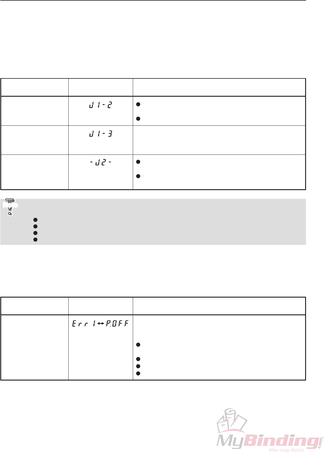
2-10
12H-M12M0-0309-0
2. ERRORS AND CAUSES
2-1. When Paper Jams Occur
When paper jams during processing or the unit is started with paper jammed inside the sensor, a warning buzzer
sounds and a message to indicate the error appears on the control panel display (see table below).
The DF-920 LCD shows the error messages on the second line, while DF-915 shows at the 7-segment window on the
right side.
When an error message is displayed, inspect near the paper feed inlet sensor or the paper ejection outlet sensor, and
remove the jammed paper.
LCD
(DF-920) Description
JAM FEED SECT
JAM INSIDE
JAM EXIT
The paper feed inlet sensor is blocked for more than the
specified distance (number of pulses) during processing.
Attempted to start with the paper feed inlet sensor blocked.
The paper ejection outlet sensor did not turn ON even though
the unit drove for the specified distance (number of pulses) after
the paper feed inlet sensor turned OFF during processing.
The paper ejection outlet sensor is blocked for more than the
specified distance (number of pulses) during processing.
Attempted to start with the paper ejection outlet sensor
blocked.
7-segment window
(DF-915)
LCD
(DF-920) Description
MOTOR ERROR 1
7-segment window
(DF-915)
The pulse output of the main motor index sensor is not normal.
<Causes>
The folding mechanism cannot operate due to paper jams,
etc.
Faulty connection between the main motor and MC unit
Malfunction of the MC unit
Malfunction of the main motor
---------------------------------------------------------------------------
(Alternately displayed)
The following causes may be suspected if error messages are displayed even though no paper jam has actually
occurred.
The paper feed inlet sensor or paper ejection outlet sensor is not secured properly.
The paper feed inlet sensor or paper ejection outlet sensor is faulty.
The connection between a paper feed inlet sensor or a paper ejection outlet sensor and MC unit is faulty.
The MC unit is faulty.
NoteNote
2-2. Troubleshooting
The DF-920 LCD shows the error messages on the second line, while DF-915 shows at the 7-segment window on the
right side (see table below).

2-11
12H-M12M0-0309-0
LCD
(DF-920) Description
MOTOR ERROR 4
MOTOR ERROR 5
MOTOR ERROR 3
MOTOR ERROR 2
7-segment window
(DF-915)
The pulse output of the folding plate 1 index sensor is not normal.
<Causes>
The folding mechanism cannot operate due to paper jam
inside folding plate 1.
Foreign objects jammed in the detecting section of the folding
plate 1 index sensor.
Faulty connection between the folding plate 1 index sensor
and MC unit
Malfunction of the folding plate 1 index sensor
Faulty connection between the folding plate 1 motor and MC
unit
Malfunction of the MC unit
Malfunction of the folding plate 1 motor
Improper adjustments of the folding plate 1 mechanism (idling
of shaft, etc.)
The pulse output of the folding plate 2 index sensor is not normal.
<Causes>
The folding mechanism cannot operate due to paper jam
inside folding plate 2.
Foreign objects jammed in the detecting section of the folding
plate 2 index sensor.
Faulty connection between the folding plate 2 index sensor
and MC unit
Malfunction of the folding plate 2 index sensor
Faulty connection between the folding plate 2 motor and MC
unit
Malfunction of the MC unit
Malfunction of the folding plate 2 motor
Improper adjustments of the folding plate 2 mechanism (idling
of shaft, etc.)
The stacker roller home sensor does not turn ON/OFF within the
specified time after the stacker roller moving motor turned ON.
<Causes>
The stacker roller mechanism cannot operate due to paper
jams, etc.
Foreign objects jammed in the detecting section of the stacker
roller home sensor.
Faulty connection between the stacker roller home sensor
and MC unit
Malfunction of the stacker roller home sensor
Faulty connection between the stacker roller moving motor
and MC unit
Malfunction of the MC unit
Malfunction of the stacker roller moving motor
Improper adjustments of the stacker roller mechanism (idling
of shaft, etc.)
The paper feed tray upper limit detection switch or paper feed
tray lower limit detection switch does not turn ON/OFF within the
specified time after the paper feed tray up/down motor turned
ON. (DF-920 only)
<Causes>
The paper feed tray up/down mechanism cannot operate due
to paper jams, etc.
Faulty connection between the upper limit detection switch or
the lower limit detection switch and MC unit
Malfunction of the upper limit detection switch or the lower
limit detection switch
Faulty connection between the paper feed tray up/down motor
and MC unit
Malfunction of the MC unit
Malfunction of the paper feed tray up/down motor
Improper adjustments of the paper feed tray up/down
mechanism (idling of shaft, etc.)
---------------------------------------------------------------------------
---------------------------------------------------------------------------
---------------------------------------------------------------------------
---------------------------------------------------------------------------
(Alternately displayed)
(Alternately displayed)
(Alternately displayed)
—

2-12
12H-M12M0-0309-0
2-3. Other Condition Messages
When covers are open or when folding plates are not set, the control panel display shows the conditions of the unit.
The DF-920 LCD shows the error messages on the second line, while DF-915 shows at the 7-segment window on the
left and right sides.
In some cases, if the message and actual condition differ such as when “TOP COVER OPEN” is displayed despite the
cover being closed, other errors may be suspected. The following table shows details.
LCD
(DF-920) Description
TOP COVER OPEN
SIDE COVER OPEN
DELIVERY COVER
F.PLAT-1 SET ERR
F.PLAT-2 SET ERR
7-segment window
(DF-915)
The contact of the top cover switch is open.
<Causes>
The top cover is not closed completely.
The top cover switch is not secured properly.
The top cover switch is broken or has malfunctioned.
Faulty connection between the top cover switch and MC unit
(Disconnection of bundled wires, improper insertion of
connectors)
Malfunction of the MC unit
The contact of the side cover switch is open. (DF-920 only)
<Causes>
The side cover is not closed completely.
The side cover switch is not secured properly.
Malfunction of the side cover switch
Faulty connection between the side cover switch and MC unit
(Disconnection of bundled wires, improper insertion of
connectors)
Malfunction of the MC unit
The paper ejection cover sensor is OFF. (DF-920 only)
∗This message is normally displayed when the start key or test
key is pressed with the paper ejection cover open. It is not
displayed at the instant the paper ejection cover is open.
<Causes>
The paper ejection cover is not closed completely.
The paper ejection cover sensor is not secured properly.
Malfunction of the paper ejection cover sensor
Faulty connection between the paper ejection cover sensor
and MC unit
(Disconnection of bundled wires, improper insertion of
connectors)
Malfunction of the MC unit
The contact of the folding plate 1 set switch is open.
<Causes>
The folding plate 1 is not set properly.
The folding plate 1 set switch is not secured properly.
Malfunction of the folding plate 1 set switch
Faulty connection between the folding plate 1 set switch and
MC unit
(Disconnection of bundled wires, improper insertion of
connectors)
Malfunction of the MC unit
The contact of the folding plate 2 set switch is open.
<Causes>
The folding plate 2 is not set properly.
The folding plate 2 set switch is not secured properly.
Malfunction of the folding plate 2 set switch
Faulty connection between the folding plate 2 set switch and
MC unit
(Disconnection of bundled wires, improper insertion of
connectors)
Malfunction of the MC unit
---------------------------------------------------------------------------
---------------------------------------------------------------------------
---------------------------------------------------------------------------
---------------------------------------------------------------------------
—
—
---------------------------------------------------------------------------

2-13
12H-M12M0-0309-0
LCD
(DF-920) Description
FEED ERROR
NO PAPER
—
PAPER SIZE ERROR
7-segment window
(DF-915)
The paper feed inlet sensor does not turn ON even though the
paper feed clutch has driven for the specified distance (number
of pulses) after it turned ON.
<Causes>
The paper stacking method on the paper feed tray is not
correct.
Paper has slipped, etc. due to insufficient paper feed
pressure, and paper is not fed correctly.
The paper separating pressure is too high.
Malfunction of the paper feed inlet sensor
Malfunction of the paper feed clutch
Faulty connection between the paper feed inlet sensor and
MC unit
(Disconnection of bundled wires, improper insertion of
connectors)
Malfunction of the MC unit
The paper switch of the paper feed tray turned OFF during
processing or attempts were made to start the unit with the
paper switch OFF.
<Causes>
Paper has run out on the paper feed tray.
Malfunction of the paper switch
Faulty connection between the paper switch and MC unit
(Disconnection of bundled wires, improper insertion of
connectors)
Malfunction of the MC unit
The paper feed tray set switch is OFF. (DF-915 only)
<Causes>
The paper feed tray is not set.
The paper feed tray set switch is not secured properly.
Malfunction of the paper feed tray set switch
Faulty connection between the paper feed tray set switch and
MC unit
(Disconnection of bundled wires, improper insertion of
connectors)
Improper adjustments of the paper feed tray mechanism
Malfunction of the MC unit
Paper less than half of the paper size set was fed.
<Causes>
Paper of different lengths are stacked together.
The stacking direction of the paper on the paper feed tray is
different.
The paper length has been registered incorrectly.
Malfunction of the paper size detection sensor
Faulty connection between the paper size detection sensor
and MC unit
(Disconnection of bundled wires, improper insertion of
connectors)
Improper adjustments of the paper feed tray mechanism
Malfunction of the MC unit
---------------------------------------------------------------------------
---------------------------------------------------------------------------
---------------------------------------------------------------------------
---------------------------------------------------------------------------
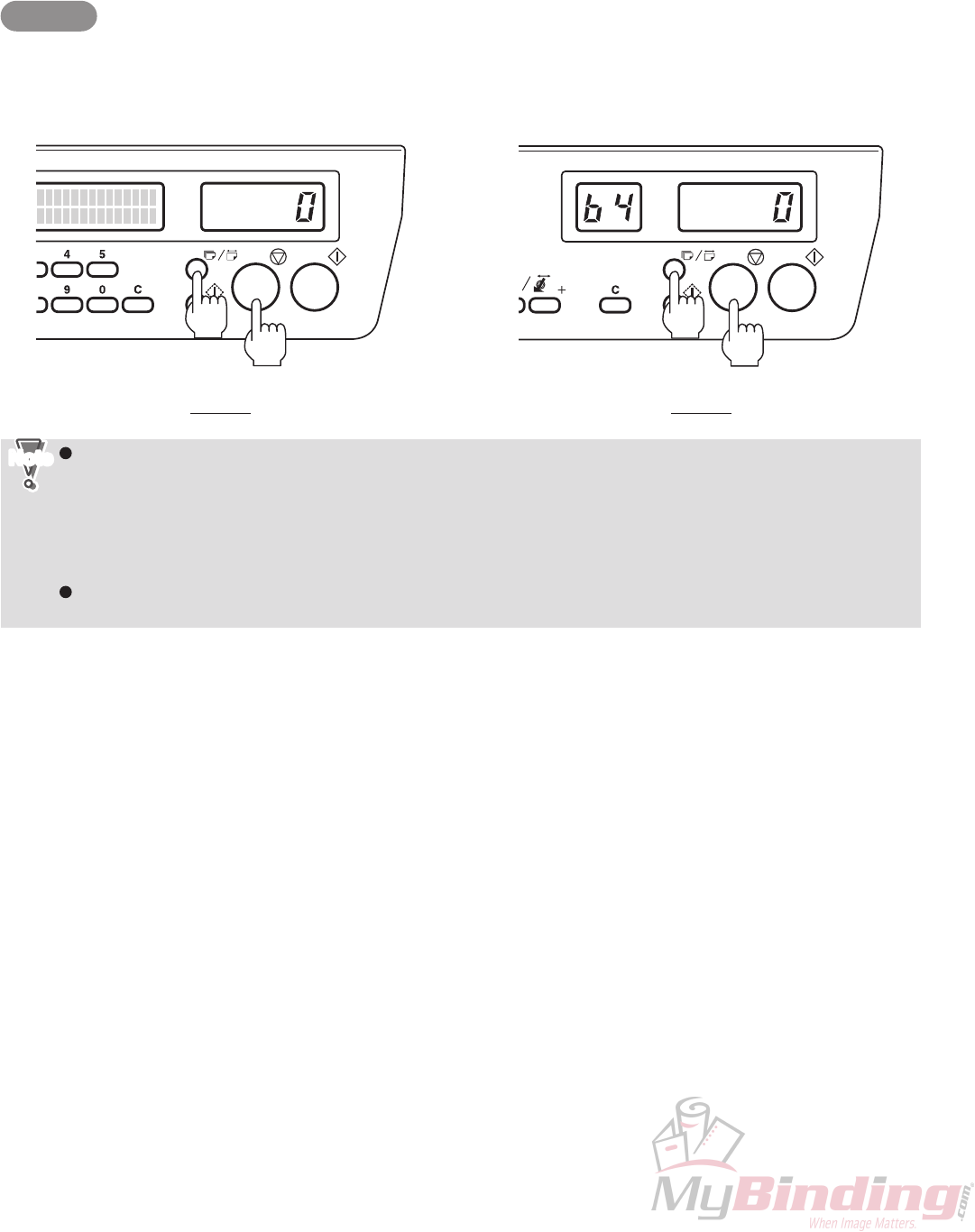
2-14
12H-M12M0-0309-0
2-4. Emergency Measures When the Paper Switch Damages
When the paper switch damages, folding operations can be performed ignoring the paper switch as an emergency
measure until the switch is replaced.
This function is available from the following ROM versions.
DF-920: 12H-80072 and later
DF-915: 12H-86041 and later
Method
Turn ON the power while pressing the stop and No. of sheets/Paper length keys simultaneously.
This enables folding operations to be carried out because the unit takes that paper is stacked even though the paper
switch is not working.
When the paper switch malfunctions, as the “no paper state” cannot be detected even though paper has run
out on the paper feed tray during folding operations, the unit proceeds feeding the next sheet of paper, after
which the whole unit stops due to paper feed error. For this reason, the folded paper is not ejected out
completed but stops near the stacker roller.
To continue paper folding in this state, replenish paper and resume operations. To end paper folding
operations, remove the folded paper near the stacker roller by hand. The folded paper can also be ejected by
pressing the test key while pressing the stop key.
As settings of this function cannot be registered in the memory, it is cleared when the power of the unit is
turned OFF.
NoteNote
DF-920 DF-915

2-15
12H-M12M0-0309-0
3. MAINTENANCE MODE
3-1. Entering the Maintenance Mode
DF-920
qTo enter the maintenance mode, turn ON the power while pressing both the start and stop keys. Or enter “920”
using the numerical keys of the initial screen displayed on the control panel (even if an error message is displayed
on the second line), and press the folding mode key while pressing the stop key.
Upon entering the maintenance mode, “MAINTENANCE MENU” is displayed on the first line of the LCD.
wEnter the one-digit or two-digit maintenance code using the numerical keys (refer to “3-3. List of Maintenance
Modes”), and press the folding mode key to enter the desired maintenance mode. If the maintenance code is not
known, press custom folding registration key 1 or 2 to select the maintenance mode. (Pressing the key
continuously switches the mode continuously.)
DF-915
qTo enter the maintenance mode, turn ON the power while pressing both the start and stop keys. Or press the
adjustment registration key while pressing both the stop key and No. of sheets/Paper length key while the unit is in
the standby state (press the adjustment registration key last).
Upon entering the maintenance mode, “– –” is displayed at the 7-segment window on the left side.
wPress the “+” or “–” key of the Paper length/Stacker roller position key and select the desired maintenance mode.
One-digit or two-digit code No. is displayed at the 7-segment window on the left side. (Pressing the key
continuously switches the mode continuously.)
3-2. Setting the Maintenance Mode
Select the desired maintenance mode, and change the settings using the “+” or “–” speed key.
To set another mode, select the maintenance mode to be set.

2-16
12H-M12M0-0309-0
3-3. List of Maintenance Modes
DF-920
The following table lists the maintenance modes of DF-920.
Code
Setting
1
2
3
4
5
6
7
8
9
10
11
12
13
14
15
16
17
18
21
22
23
24
25
26
27
28
31
32
33
34
36
1st line of LCD 2nd line of LCD
(Setting at shipment)
Folding plate 1 home position adjustment
Folding plate 2 home position adjustment
Switching shaft home position adjustment
Destination setting
mm/inch display setting
Language setting
No. of test folding sheets setting
Backlight automatic OFF setting
Buzzer ON/OFF setting
Power still ON alert setting
Speed 1 adjustment
Processing speed adjustment
Operation mode setting
Total counter
MC ROM version display
OP ROM version display
Paper ejection cover detection ON/OFF setting
Program version up mode
Main motor test
Folding plate motor test
Stacker roller moving motor test
Paper feed tray up/down motor test
Paper feed clutch test
Paper ejection clutch test
Simulation mode
Folding stopper parallelity mode
Sensor/switch check
Paper size detection sensor check
Main motor index sensor check
Folding plate index sensor check
Panel check mode
Note 1
Note 2
Note 3
UK (USA)
MILLIMETER (INCH)
ENGLISH
2 SHEETS
30 SEC
ON
OFF
NORMAL
NORMAL
OFF
0000000
12H-8∗∗∗∗
12∗8∗∗∗∗
ON
RUN W/O PAPER
ABCDEFGHIJKLM
–– –––
0000
1:0000 / 2:0000
1.STOP1 DEFAULT
2.STOP2 DEFAULT
3.SW BAR ADJUST
4.AREAS
5.SET MM/INCH
6.LANGUAGES
7.TEST FOLD QTY
8.BACK LIGHT OFF
9.BUZZ ON/OFF
10.POWER ON BUZZ
11.SPEED1 ADJUST
12.SPEED ADJUST
13.SET FUNCTION
14.TOTAL COUNTER
15.MC ROM VER
16.PANEL ROM VER
17.DEL CVR SNSR
18.PROG VER UP
21.MAIN MTR TEST
22.F.PLATE MOTOR
23.STACK ROL MTR
24.FEED TRAY MTR
25.FEED CLUTCH
26.DLVRY CLUTCH
27.SIMULATION
28.ALIGNMENT
31.CHK SENSOR SW
32.CHK SIZE SNSR
33.MAIN MTR INDX
34.F.PLATE INDEX
36.PANEL CHECK
Code No.19, 20, 29, 30, and 35 are currently not used.
The Note 1 to 3 settings differ by machine because they are finely adjusted at shipment.
NoteNote

2-17
12H-M12M0-0309-0
(1) Folding plate 1 home position adjustment (Code No.1)
Mode for adjusting the home position of folding plate 1.
“2-6-14. (1) Adjusting folded size by folding plate 1” in CHAPTER 1 MECHANISM
eSee
This setting differs by machine because it is finely adjusted at shipment.
The setting at shipment is indicated on the backup data form inside the operating side cover.
To change the setting, first note down the current value. After changing the setting, fill in the new value in
the backup data form.
NoteNote
(2) Folding plate 2 home position adjustment (Code No.2)
Mode for adjusting the home position of folding plate 2.
“2-6-14. (2) Adjusting folded size by folding plate 2” in CHAPTER 1 MECHANISM
eSee
This setting differs by machine because it is finely adjusted at shipment.
The setting at shipment is indicated on the backup data form inside the operating side cover.
To change the setting, first note down the current value. After changing the setting, fill in the new value in
the backup data form.
NoteNote
(3) Switching shaft home position adjustment (Code No.3)
Mode for adjusting the home position of the switching shaft.
“2-6-11. Adjusting the home position of the switching shaft (stopping position) in single folding” in
CHAPTER 1 MECHANISM
eSee
This setting differs by machine because it is finely adjusted at shipment.
The setting at shipment is indicated on the backup data form inside the operating side cover.
To change the setting, first note down the current value. After changing the setting, fill in the new value in
the backup data form.
NoteNote
(4) Destination setting (Code No.4)
Mode for setting the destination. Can be set to “JAPAN”, “USA”, or “UK”.
At shipment, this is set according to the destination of the unit.
When the EEPROM is initialized, it is set to “JAPAN”.
Changing the destination setting does not change the (5) mm/inch display setting and (6) language setting.
These settings must be changed separately.
NoteNote
(5) mm/inch display setting (Code No.5)
Mode for setting the unit of the size displayed on the LCD or 7-segment window. Can be set to “MILLIMETER” or
“INCH”.
At shipment, this is set to mm for Japanese and UK models and to inch for USA model.
When the EEPROM is initialized, it is set to “MILLIMETER”.
(6) Language setting (Code No.6)
Mode for setting the language of the messages displayed on the LCD. Can be set to “JAPANESE” or “ENGLISH”.
At shipment, this is set to “JAPANESE” for Japanese model and to “ENGLISH” for USA and UK models.
When the EEPROM is initialized, it is set to “ENGLISH”.
(7) No. of test folding sheets setting (Code No.7)
Mode for setting the number of sheets to be test folded. Can be set within 1 to 3 sheets.
At shipment, this is set to “2 SHEETS”.
(8) Backlight automatic OFF setting (Code No.8)
Mode for setting the time for the LCD backlight to go OFF automatically when not using the unit. Can be set to “15
SEC”, “30 SEC”, “60 SEC”, or “KEEP LIGHT ON” (always ON).
At shipment, this is set to “30 SEC”.

2-18
12H-M12M0-0309-0
(9) Buzzer ON/OFF setting (Code No.9)
Mode for setting ON/OFF the buzzer which sounds during key operations, when a process ends, or when errors
occur. Can be set to “ON” or “OFF”.
At shipment, this is set to “ON”.
A warning buzzer sounds when motor problems occur even if this setting is set to “OFF”. (It will not sound
when errors such as paper jams, etc. occur.)
NoteNote
(10) Power still ON alert setting (Code No.10)
Mode for setting the time to sounding a buzzer to alert that the power is still ON when the unit is not used. Can be
set to “OFF” (buzzer not sounded), “5 MIN”, “15 MIN”, or “30 MIN”.
At shipment, this is set to “OFF”.
(11) Speed 1 adjustment (Code No.11)
Mode for setting the folding roller speed when processing speed is set to 1. Can be set to “NORMAL” or “SLOW”.
At shipment, this is set to “NORMAL”.
When folding thin and flimsy paper, folding problems may occur if the processing speed is set to 1. In such cases,
set to “SLOW”.
The speed of processing speed 1 when set to “NORMAL” is about 460 mm/s. Setting to “SLOW” lowers
the speed to about 290 mm/s.
When set to “SLOW”, the processing speed 1 LED blinks.
When set to “SLOW” and firm paper is used, the main motor may lock due to load.
NoteNote
(12) Processing speed adjustment (Code No.12)
Mode for finely adjusting the speed when the processing speed does not satisfy the specifications
(200 sheets/minute in single folding of B4 paper, 255 sheets/minute in single folding of letter size paper
for USA). Can be set to “NORMAL”, “FAST”, or “SLOW”.
At shipment, this is set to “NORMAL”.
When the EEPROM is initialized, it is set to “NORMAL”.
(13) Operation mode setting (Code No.13)
Mode for setting the operation mode of the unit. Can be set to “OFF”, “LAST TIME FOLD”, or “STOPPER FIXED”.
At shipment, this is set to “OFF”.
+5%
–1% +5%
–1%
When set to “STOPPER FIXED”, after exiting the maintenance mode, be sure to press the clear key while
pressing the stop key to perform initialization. Initialization is not carried out even if the power is turned
OFF and then ON again. Using the unit without performing initialization may result in incorrect
operations.
The operation mode can be set without entering the maintenance mode. (Refer to the instruction manual.)
NoteNote
(14) Total counter (Code No.14)
Displays the total number of sheets fed into the machine.
(15) MC ROM version display (Code No.15)
Displays the program version of the microprocessor of the MC unit.
(16) OP ROM version display (Code No.16)
Displays the version of the OP unit.
(17) Paper ejection cover detection ON/OFF setting (Code No.17)
Mode for turning the paper ejection cover detection ON/OFF. Can be set to “ON” or “OFF”.
At shipment, this is set to “ON”.
(18) Program version up mode (Code No.18)
Mode for upgrading the program version.
“7. UPGRADING THE PROGRAM VERSION”
See

2-19
12H-M12M0-0309-0
(19) Main motor test (Code No.21)
Mode for checking the operations of the main motor.
The main motor rotates when the start key is pressed, and stops when the stop key is pressed.
The rotating speed can also be changed using the speed key.
The motor will not rotate if any one interlock switch is not closed.
NoteNote
(20) Folding plate motor test (Code No.22)
Mode for checking operations of the motor for moving the folding stoppers of folding plate 1 and 2.
Pressing the “+” key of the folding plate 1 folding stopper adjusting key rotates the folding plate 1 motor, and
moves the folding stopper in the reverse home position direction. Pressing the “–” key rotates the folding plate 1
motor, and moves the folding stopper in the home position direction.
Pressing the “+” key of the folding plate 2 folding stopper adjusting key rotates the folding plate 2 motor, and
moves the folding stopper in the reverse home position direction. Pressing the “–” key rotates the folding plate 2
motor, and moves the folding stopper in the home position direction.
The motor rotates while the key is pressed, and stops when the key is released.
As the motor rotates regardless of the limit detection by the home sensor and index sensor, make sure
that the folding stopper does not clash into the limit section of the folding plate.
The motor will not rotate if any one interlock switch is not closed.
NoteNote
(21) Stacker roller moving motor test (Code No.23)
Mode for checking operations of the stacker roller moving motor.
Pressing the “+” key of the folding plate 2 folding stopper adjusting key rotates the stacker roller moving motor,
and moves the stacker roller outside. Pressing the “–” key rotates the stacker roller moving motor, and moves the
stacker roller inside.
The motor rotates while the key is pressed, and stops when the key is released.
Pressing the “+” key continuously moves the stacker roller outside the unit and locks the motor.
The motor will not rotate if any one interlock switch is not closed.
NoteNote
(22) Paper feed tray up/down motor test (Code No.24)
Mode for checking operations of the paper feed tray up/down motor.
Pressing the “+” key of the folding plate 1 folding stopper adjusting key rotates the paper feed tray up/down motor,
and raises the paper feed tray. Pressing the “–” key rotates the paper feed tray up/down motor, and lowers the
paper feed tray.
The motor rotates while the key is pressed, and stops when the key is released.
The motor will not rotate if any one interlock switch is not closed.
NoteNote
(23) Paper feed clutch test (Code No.25)
Mode for checking the operations of the paper feed clutch.
The paper feed clutch operates when the start key is pressed, and stops when the stop key is pressed.
Do not leave the unit with the clutch operating. Otherwise, the clutch will overheat, resulting in malfunction.
NoteNote
(24) Paper ejection clutch test (Code No.26)
Mode for checking the operations of the paper ejection clutch.
The paper ejection clutch operates when the start key is pressed, and stops when the stop key is pressed.
Do not leave the unit with the clutch operating. Otherwise, the clutch will overheat, resulting in malfunction.
NoteNote

2-20
12H-M12M0-0309-0
(26) Folding stopper parallelity mode (Code No.28)
Mode for making the folding stoppers of folding plates 1 and 2 parallel.
“2-6-10. Adjusting the parallelity of the folding stoppers” in CHAPTER 1 MECHANISM
(27) Sensor/switch check (Code No.31)
Mode for checking the states of sensors and switches.
Sensors and switches which are ON are displayed in alphabet at the second line of the LCD. Those which are
OFF are displayed as “–”.
The displays correspond to sensors and switches from the left side in the following order.
[A] Paper feed inlet sensor →[B] Paper ejection outlet sensor →[C] Paper switch →
[D] Stacker roller home sensor →[E] Folding plate 1 home sensor →
[F] Folding plate 2 home sensor →[G] Paper feed tray upper limit detection switch →
[H] Paper feed tray lower limit detection switch →[I] Paper ejection cover sensor →
[J] Top cover switch →[K] Side cover switch →[L] Folding plate 1 set switch →
[M] Folding plate 2 set switch
Turning sensors and switches ON/OFF changes the corresponding display (alphabet or “–”), and a buzzer
sounds.
(28) Paper size detection sensor check (Code No.32)
Mode for checking the state of the paper size detection sensor.
Sensors which are ON are displayed as “ ” at the second line of the LCD, and those which are OFF are
displayed as “–”. UK model displays correspond to the B6, A5, B5, A4, B4, and A3 paper size detection sensors
from the left side in order.
For USA models, “ ” is displayed at the leftmost side, and the second display onwards corresponds to the INV,
STMT, LTR, LGR, and LGL paper size detection sensors in order.
The displays change when the paper feed guides are moved, and a buzzer sounds.
See
The LGL detection sensor is the opposite to other sensors, in that “–” is displayed when it is ON, and “ ”
when OFF.
NoteNote
(29) Main motor index sensor check (Code No.33)
Mode for checking the index sensor inside the main motor.
When the main motor shaft is rotated by rotating the jam correction knob or center press roller, pulse input is
performed, and the number of pulses is counted up and displayed at the second line of the LCD.
When the main motor shaft is rotated once, and the number of pulses should be added with 15.
The number of pulses displayed is reset to 0 when the power is turned OFF.
The number of pulses is counted up even if the main motor shaft is rotated in the normal or reverse
directions.
NoteNote
(30) Folding plate index sensor check (Code No.34)
Mode for checking the index sensor of folding plates 1 and 2.
Check the changes in the states of each sensor by looking at the changes in the number of pulses displayed at
the second line of the LCD.
Pressing the “+” key of the folding plate 1 folding stopper adjusting key counts up the number of pulses displayed
at the left side of the second line of the LCD, and pressing the “–” key counts down the display.
Pressing the “+” key of the folding plate 2 folding stopper adjusting key counts up the number of pulses displayed
at the right side of the second line of the LCD, and pressing the “–” key counts down the display.
If the direction which changes the number of pulses is opposite to the above, check if the connectors of
index sensors A and B of the corresponding folding plate are connected reverse.
NoteNote
(25) Simulation mode (Code No.27)
Mode for operating each mechanism without using paper.
The simulation mode operates when the start key is pressed, and stops when the stop key is pressed.
If operating the unit in the simulation mode, be sure to remove the paper feed ring.
NoteNote

2-21
12H-M12M0-0309-0
(31) Panel check mode (Code No.36)
Mode for checking the LEDs and 7-segment of the control panel.
Pressing the start key lights up the whole 7-segment, and pressing the stop key lights up all LEDs. (Some LEDs
may blink depending on the other settings of the maintenance mode.)
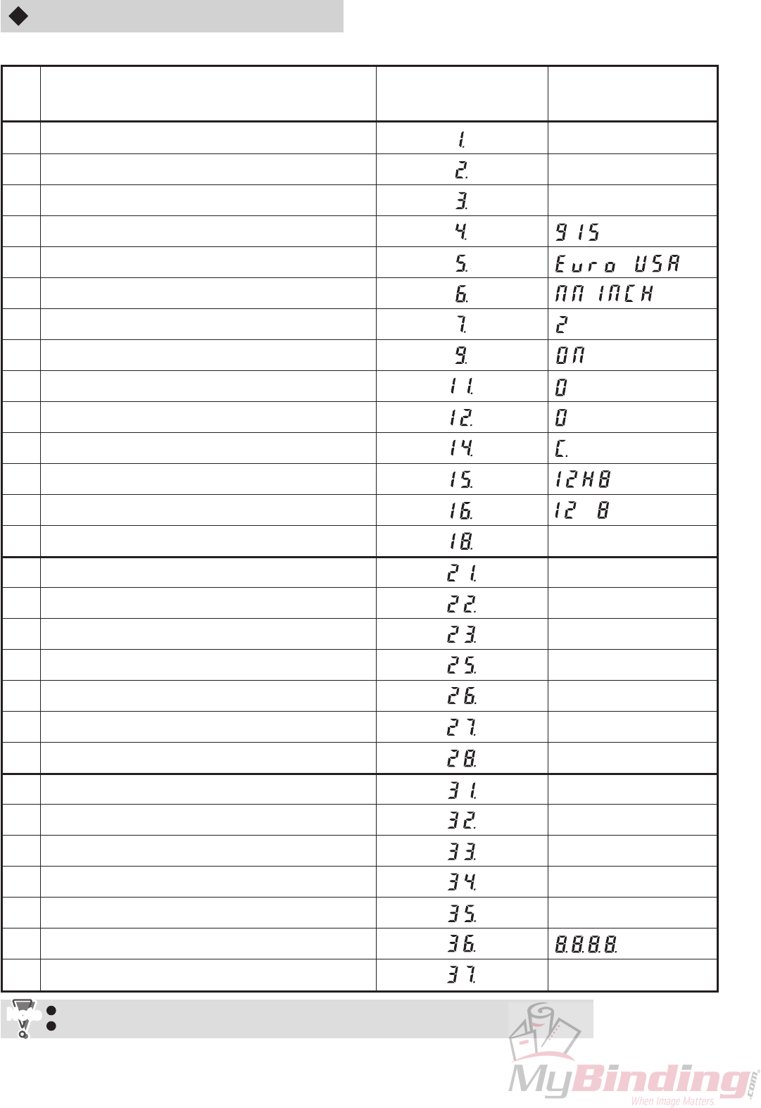
2-22
12H-M12M0-0309-0
Code No.8, 10, 13, 17, 19, 20, 24, 29, and 30 are currently not used.
The Note 1 to 3 settings differ by machine because they are finely adjusted at shipment.
NoteNote
Code
Setting
1
2
3
4
5
6
7
9
11
12
14
15
16
18
21
22
23
25
26
27
28
31
32
33
34
35
36
37
7-segment window
(Left side, 2 digits)
7-segment window
(Right side, 4 digits)
(Setting at shipment)
Folding plate 1 home position adjustment
Folding plate 2 home position adjustment
Switching shaft home position adjustment
Model setting
Destination setting
mm/inch display setting
No. of test folding sheets setting
Buzzer ON/OFF setting
Speed 1 adjustment
Processing speed adjustment
Total counter
MC ROM version display
OP ROM version display
Program version up mode
Main motor test
Folding plate motor test
Stacker roller moving motor test
Paper feed clutch test
Paper ejection clutch test
Simulation mode
Folding stopper parallelity mode
Sensor check (1)
Sensor check (2)
Switch check
Paper size detection sensor check (1)
Paper size detection sensor check (2)
Panel check mode
Motor index sensor check
Note 1
Note 2
Note 3
()
()
∗∗∗ ⇔ ∗∗∗∗
⇔ ∗∗∗∗
∗ ⇔ ∗∗∗∗
∗∗∗∗
∗∗∗
∗∗∗
∗∗∗∗
∗∗
∗∗∗∗
DF-915
The following table lists the maintenance modes of DF-915.

2-23
12H-M12M0-0309-0
(1) Folding plate 1 home position adjustment (Code No.1)
Mode for adjusting the home position of folding plate 1.
“2-6-14. (1) Adjusting folded size by folding plate 1” in CHAPTER 1 MECHANISM
eSee
This setting differs by machine because it is finely adjusted at shipment.
The setting at shipment is indicated on the backup data form inside the operating side cover.
To change the setting, first note down the current value. After changing the setting, fill in the new value in
the backup data form.
NoteNote
(2) Folding plate 2 home position adjustment (Code No.2)
Mode for adjusting the home position of folding plate 2.
“2-6-14. (2) Adjusting folded size by folding plate 2” in CHAPTER 1 MECHANISM
eSee
This setting differs by machine because it is finely adjusted at shipment.
The setting at shipment is indicated on the backup data form inside the operating side cover.
To change the setting, first note down the current value. After changing the setting, fill in the new value in
the backup data form.
NoteNote
(3) Switching shaft home position adjustment (Code No.3)
Mode for adjusting the home position of the switching shaft.
“2-6-11. Adjusting the home position of the switching shaft (stopping position) in single folding” in
CHAPTER 1 MECHANISM
eSee
This setting differs by machine because it is finely adjusted at shipment.
The setting at shipment is indicated on the backup data form inside the operating side cover.
To change the setting, first note down the current value. After changing the setting, fill in the new value in
the backup data form.
NoteNote
(5) Destination setting (Code No.5)
Mode for setting the destination. Can be set to “JPN” (JAPAN), “USA”, or “Euro” (UK).
At shipment, this is set according to the destination of the unit.
When the EEPROM is initialized, it is set to “JPN”.
Changing the destination setting does not change the (4) Model setting and (6) mm/inch display setting.
These settings must be changed separately.
NoteNote
(6) mm/inch display setting (Code No.6)
Mode for setting the unit of the size displayed on the 7-segment window. Can be set to “NN” (mm) or “INCH”.
At shipment, this is set to mm for Japanese and UK models and to inch for USA model.
When the EEPROM is initialized, it is set to “NN”.
(7) No. of test folding sheets setting (Code No.7)
Mode for setting the number of sheets to be test folded. Can be set within 1 to 3 sheets.
At shipment, this is set to “2”.
(4) Model setting (Code No.4)
Mode for setting the model.
Can be set to “915” (DF-915) or “910” (DF-910).
At shipment, Japanese model is set to “910” and UK, USA models are set to “915”.
When the EEPROM is initialized, it is set to “915”.
Changing the model setting does not change the (5) Destination setting and (6) mm/inch display setting.
These settings must be changed separately.
NoteNote

2-24
12H-M12M0-0309-0
(8) Buzzer ON/OFF setting (Code No.9)
Mode for setting ON/OFF the buzzer which sounds during key operations, when a process ends, or when errors
occur. Can be set to “ON” or “OFF”.
At shipment, this is set to “ON”.
A warning buzzer sounds when motor problems occur even if this setting is set to “OFF”. (It will not sound
when errors such as paper jams, etc. occur.)
NoteNote
(9) Speed 1 adjustment (Code No.11)
Mode for setting the folding roller speed when processing speed is set to 1. Can be set to “0” (NORMAL) or “–1”
(SLOW).
At shipment, this is set to “0”.
When folding thin and flimsy paper, folding problems may occur if the processing speed is set to 1. In such cases,
set to “–1”.
The speed of processing speed 1 when set to “0” is about 460 mm/s. Setting to “–1” lowers the speed to
about 290 mm/s.
When set to “–1”, the processing speed 1 LED blinks.
When set to “–1” and firm paper is used, the main motor may lock due to load.
NoteNote
(10) Processing speed adjustment (Code No.12)
Mode for finely adjusting the speed when the processing speed does not satisfy the specifications
(200 sheets/minute in single folding of B4 paper, 255 sheets/minute in single folding of letter size paper
for USA). Can be set to “0” (NORMAL), “1” (FAST), or “–1” (SLOW).
At shipment, this is set to “0”.
When the EEPROM is initialized, it is set to “0”.
(11) Total counter (Code No.14)
Displays the total number of sheets fed into the machine. (7 digits)
At the 7-segment window on the right side, the first three digits “C.∗∗∗” and last four digits “∗∗∗∗” are displayed
alternately for one second each.
Example) “C.123” and “4567” are displayed alternately for one second each.
→ This means that the total number of sheets fed into the machine is 1234567.
(12) MC ROM version display (Code No.15)
Displays the program version of the microprocessor of the MC unit.
The program version is “12H-8∗∗∗∗”, but at the 7-segment window on the right side, the first four digits “12H8”
and last four digits “∗∗∗∗” are displayed alternately for one second each.
(13) OP ROM version display (Code No.16)
Displays the version of the OP unit.
At the 7-segment window on the right side, the first four digits “12∗8” and last four digits “∗∗∗∗” are displayed
alternately for one second each.
(14) Program version up mode (Code No.18)
Mode for upgrading the program version.
“7. UPGRADING THE PROGRAM VERSION”
(15) Main motor test (Code No.21)
Mode for checking the operations of the main motor.
The main motor rotates when the start key is pressed, and stops when the stop key is pressed.
The rotating speed can also be changed using the speed key.
+5%
–1% +5%
–1%
See
The motor will not rotate if any one interlock switch is not closed.
NoteNote

2-25
12H-M12M0-0309-0
(16) Folding plate motor test (Code No.22)
Mode for checking operations of the motor for moving the folding stoppers of folding plate 1 and 2.
Pressing the “+” key of the folding plate 1 folding stopper adjusting key rotates the folding plate 1 motor, and
moves the folding stopper in the reverse home position direction. Pressing the “–” key rotates the folding plate 1
motor, and moves the folding stopper in the home position direction.
Pressing the “+” key of the folding plate 2 folding stopper adjusting key rotates the folding plate 2 motor, and
moves the folding stopper in the reverse home position direction. Pressing the “–” key rotates the folding plate 2
motor, and moves the folding stopper in the home position direction.
The motor rotates while the key is pressed, and stops when the key is released.
As the motor rotates regardless of the limit detection by the home sensor and index sensor, make sure
that the folding stopper does not clash into the limit section of the folding plate.
The motor will not rotate if any one interlock switch is not closed.
NoteNote
(17) Stacker roller moving motor test (Code No.23)
Mode for checking operations of the stacker roller moving motor.
Pressing the “+” key of the folding plate 2 folding stopper adjusting key rotates the stacker roller moving motor,
and moves the stacker roller outside. Pressing the “–” key rotates the stacker roller moving motor, and moves the
stacker roller inside.
The motor rotates while the key is pressed, and stops when the key is released.
Pressing the “+” key continuously moves the stacker roller outside the unit and locks the motor.
The motor will not rotate if any one interlock switch is not closed.
NoteNote
(18) Paper feed clutch test (Code No.25)
Mode for checking the operations of the paper feed clutch.
The paper feed clutch operates when the start key is pressed, and stops when the stop key is pressed.
Do not leave the unit with the clutch operating. Otherwise, the clutch will overheat, resulting in malfunction.
NoteNote
(19) Paper ejection clutch test (Code No.26)
Mode for checking the operations of the paper ejection clutch.
The paper ejection clutch operates when the start key is pressed, and stops when the stop key is pressed.
Do not leave the unit with the clutch operating. Otherwise, the clutch will overheat, resulting in malfunction.
NoteNote
(20) Simulation mode (Code No.27)
Mode for operating each mechanism without using paper.
The simulation mode operates when the start key is pressed, and stops when the stop key is pressed.
If operating the unit in the simulation mode, be sure to remove the paper feed ring.
NoteNote
(21) Folding stopper parallelity mode (Code No.28)
Mode for making the folding stoppers of folding plates 1 and 2 parallel.
“2-6-10. Adjusting the parallelity of the folding stoppers” in CHAPTER 1 MECHANISM
(22) Sensor check (1) (Code No.31)
Mode for checking the states of each sensor.
At the 7-segment window on the right side, sensors which are ON are displayed as “1” and those which are OFF
are displayed as “0”.
The display corresponds to each sensor in the following order.
Paper feed inlet sensor →Paper ejection outlet sensor →Paper switch →Paper feed tray set switch
Turning ON/OFF the sensors changes the corresponding display (“1” or “0”) and a buzzer sounds.
eSee

2-26
12H-M12M0-0309-0
(23) Sensor check (2) (Code No.32)
Mode for checking the states of each sensor.
At the 7-segment window on the right side, sensors which are ON are displayed as “1” and those which are OFF
are displayed as “0”.
The display corresponds to each sensor in the following order.
Stacker roller home sensor →Folding plate 1 home sensor →Folding plate 2 home sensor
Turning ON/OFF the sensors changes the corresponding display (“1” or “0”) and a buzzer sounds.
(24) Switch check (Code No.33)
Mode for checking the states of each switch.
At the 7-segment window on the right side, switches which are ON are displayed as “1” and those which are OFF
are displayed as “0”.
The display corresponds to each switch in the following order.
Top cover switch →Folding plate 1 set switch →Folding plate 2 set switch
Turning ON/OFF the switches changes the corresponding display (“1” or “0”) and a buzzer sounds.
(25) Paper size detection sensor check (1) (Code No.34)
Mode for checking the state of the paper size detection sensor.
At the 7-segment window on the right side, sensors which are ON are displayed as “1” and those which are OFF
are displayed as “0”. UK model displays correspond to the B6, A5, B5, and A4 paper size detection sensors from
the left side in order.
For USA models, “1” is displayed at the leftmost side, and the second display onwards corresponds to the INV,
STMT, and LTR paper size detection sensors in order.
The displays change when the paper feed guides are moved, and a buzzer sounds.
(26) Paper size detection sensor check (2) (Code No.35)
Mode for checking the state of the paper size detection sensor.
At the 7-segment window on the right side, sensors which are ON are displayed as “1” and those which are OFF
are displayed as “0”. UK model displays correspond to the B4 and A3 paper size detection sensors from the left
side in order.
USA model displays correspond to the LGR and LGL paper size detection sensors from the left side in order.
The displays change when the paper feed guides are moved, and a buzzer sounds.
The LGL detection sensor is the opposite to other sensors, in that “0” is displayed when it is ON, and “1”
when OFF.
NoteNote
(27) Panel check mode (Code No.36)
Mode for checking the LEDs and 7-segment window of the control panel.
Pressing the start key lights up the whole 4-digit 7-segment window on the right side, and pressing the stop key
lights up the 2-digit 7-segment window on the left side and all LEDs. (Some LEDs may blink depending on the
other settings of the maintenance mode.)

2-27
12H-M12M0-0309-0
(28) Motor index sensor check (Code No.37)
Mode for checking the index sensors in the main motor and index sensors of folding plates 1 and 2.
Checking the main motor index sensor
When the main motor shaft is rotated by rotating the jam correction knob or center press roller, pulse input is
performed, and the number of pulses is counted up and displayed at the 7-segment window on the right side.
When the main motor shaft is rotated once, and the number of pulses should be added with 15.
The number of pulses displayed is reset to 0 when the power is turned OFF.
The number of pulses is counted up even if the main motor shaft is rotated in the normal or reverse
directions.
NoteNote
Checking the folding plate 1, 2 index sensor
Check the changes in the states of each sensor by looking at the changes in the number of pulses displayed at
the 7-segment window on the right side.
Pressing the “+” key of the folding plate 1 folding stopper adjusting key counts up the number of pulses displayed,
and pressing the “–” key counts down the display.
Pressing the “+” key of the folding plate 2 folding stopper adjusting key counts up the number of pulses displayed,
and pressing the “–” key counts down the display.
If the direction which changes the number of pulses is opposite to the above, check if the connectors of
index sensors A and B of the corresponding folding plate are connected reverse.
NoteNote
3-4. Precautions for Setting Folding Stopper Fixed Mode (DF-920 only)
When the operation mode is set to the folding stopper fixed mode, if moving the position of the folding stopper for
folding plate motor tests or folding plate index sensor check, be sure to turn OFF the power once, and then turn it ON
again to perform initialization before starting folding operations, and re-check the positions of the folding stoppers.
Starting without performing initialization will result in folding operations at the incorrect stopper position.
Perform initialization by pressing the clear key while pressing the stop key after turning ON the power.
Initialization will be performed automatically when the clear key is pressed twice from the maintenance mode to
return to the normal mode.
NoteNote

2-28
12H-M12M0-0309-0
4. BACKUP DATA FORM
A backup data form is pasted on the inside of the main cover F (control panel side) for noting down various setting
data such as home position adjustment data of folding plates and switching shaft.
If the corresponding setting data has been changed in the maintenance mode, be sure to fill in the changed data in this
backup data form.
Code
Function
STOP1 DEFAULT
SER.No. 120V, 60Hz
220Ð240V, 50Hz
DF-920
STOP2 DEFAULT
SW BAR ADJUST
AREAS
SET MM/INCH
LANGUAGES
TEST FOLD QTY
BACK LIGHT OFF
BUZZ ON/OFF
POWER ON BUZZ
SPEED1 ADJUST
SPEED ADJUST
SET FUNCTION
TOTAL COUNTER
MC ROM VER
DEL CVR SNSR
∗
Code numbers are derived from the code numbers in the maintenance mode table.
When changing data, follow the maintenance manual.
NOTE: Changing data at code numbers 1 Ð 3 may cause a degradation in fold accuracy.
Default
Correction Range
DATE
INIT12345
10 Ð20 Ð +20
0 Ð20 Ð +20
Ð4 Ð20 Ð +5
JAPAN
JAPAN, USA, UK
ON ONON ⇔ OFF
ON ON
ON ⇔ OFF
OFF OFF
5, 15, 30 MIN,
OFF
OFF OFF
0000000 0000000
LAST TIME FOLD
STOPPER FIXED
OFF
MM MM, INCH
NORMAL NORMAL
SLOW, NORMAL
12H-8007X
NORMAL NORMAL
SLOW, NORMAL,
FAST
221Ð3 SHEETS
30 SEC 30 SEC
15, 30, 60 SEC,
KEEP LIGHT ON
ENGLISH ENGLISH
JAPANESE
ENGLISH
2
3
4
5
6
7
8
9
10
11
12
13
14
15
17
Part Number : 12H-9132X

2-29
12H-M12M0-0309-0
Code
Function
STOP1 DEFAULT
SER.No. 120V, 60Hz
220Ð240V, 50Hz
DF-915
STOP2 DEFAULT
SW BAR ADJUST
AREAS
SET MM/INCH
TEST FOLD QTY
BUZZ ON/OFF
SPEED1 ADJUST
SPEED ADJUST
TOTAL COUNTER
MC ROM VER
∗Code numbers are derived from the code numbers in the maintenance mode table.
When changing data, follow the maintenance manual.
NOTE: Changing data at code numbers 1 Ð 3 may cause a degradation in fold accuracy.
Default
Correction Range
DATE INIT12345
10Ð20 Ð +20
0Ð20 Ð +20
Ð4Ð20 Ð +5
JPN
JPN, USA, Euro
ON ONON ⇔ OFF
00
C. 0000000 C. 0000000
NN NN, INCH
00
0
Ð1: NORMAL
: SLOW
1
0
Ð1
: FAST
: NORMAL
: SLOW
12H-8604X
221Ð 3
2
3
5
MODEL CODE 915 915915, 9104
6
7
9
11
12
14
15
Part Number : 12H-9133X

2-30
12H-M12M0-0309-0
5. INITIALIZING THE MEMORY
If for some reason, the EEPROM (nonvolatile memory) data becomes lost and the display does not function normally,
initialize and recover the data using the following procedure.
Initializing the memory
qWhile pressing the start key, stop key, and test key together, turn ON the power. This initializes data except for the
total count registered in the EEPROM of the MC unit. A buzzer sounds three times when the memory is initialized.
wAs the data except for the total count was initialized, reset data such as home position adjustment data of folding
plates and switching shaft in the maintenance mode while checking the backup data form pasted on the inside of
the main cover F.
If data cannot be recovered by the above method, turn ON the power while pressing the start key, stop key,
and clear key together (This initializes all data including the total count). Never perform this method except
when problems have occurred.
Turning ON the power while pressing the test key erases only standard folding adjustment registration and
custom folding registration data.
NoteNote

2-31
12H-M12M0-0309-0
6. PRECAUTIONS ON REPLACING THE MC UNIT
Various data such as home position adjustment data of folding plates and switching shaft and total count memorized
by the unit even when the power has been turned OFF are registered in the EEPROM (nonvolatile memory) of the MC
unit (board). Therefore if the MC unit has been replaced, attach the EEPROM of the old MC board to the new board if
possible.
If board replacement can only be done as a whole together with the EEPROM, note down various settings and total
count data before replacement on the backup data form pasted on the inside of the main cover F, perform the next
step after replacement, and check the data.
(1) Initializing the memory
While pressing the start key, stop key, and clear key together, turn ON the power. This initializes data registered
in the EEPROM of the MC unit. A buzzer sounds three times when the memory is initialized.
(2) Setting various data
Reset data such as home position adjustment data of folding plates and switching shaft in the maintenance mode
as required.
When attaching the EEPROM, take note of the socket direction.
NoteNote

2-32
12H-M12M0-0309-0
7. UPGRADING THE PROGRAM VERSION
When upgrading the control program version, prepare a 1M-byte EPROM written with the new version program
(Equivalent to STMicroelectronics M27C1001-12F1), and rewrite using the following procedure.
qInsert the EPROM written with the new version program into the IC socket of the MC unit (board) with the power
OFF.
wWhile pressing the start key and stop key, turn ON the power. (To enter the maintenance mode)
eFor DF-920, enter the code No. “18” of the maintenance mode using the numerical keys, and press the folding
mode key. (To enter the program version up mode)
For DF-910, select code No. “18” using the Paper length/Stacker roller position key. (Do not use the folding mode
key.)
rPress the start key. (The buzzer will not sound even when the start key is pressed, but this is not a fault.)
When attaching the EPROM, take note of the socket direction.
NoteNote
Never turn OFF the power until rewriting has been completed.
If rewriting is started normally, all keys will be ineffective until rewriting completes. This is not a fault.
If the buzzer sounds “pi.pi.pi” when the start key is pressed, it indicates the ID error of the program. The
following reasons are possible.
• The EPROM is not inserted in the socket correctly
• The program is not written in the EPROM correctly.
• A program with a different ID is written in the EPROM.
NoteNote
tAfter 15 to 20 seconds later, rewriting completes normally, and the new program starts running automatically.
(The same operations are performed when the power is turned ON normally.)
As motors will operate if all interlock switches are turned ON even if the operation is carried out with the
cabinet cover removed, do not touch the driving parts.
NoteNote
yCheck that the maintenance mode “Code No.15: MC ROM version display” is set and the new version is displayed.
uTurn OFF the power, and remove the EPROM from the IC socket.
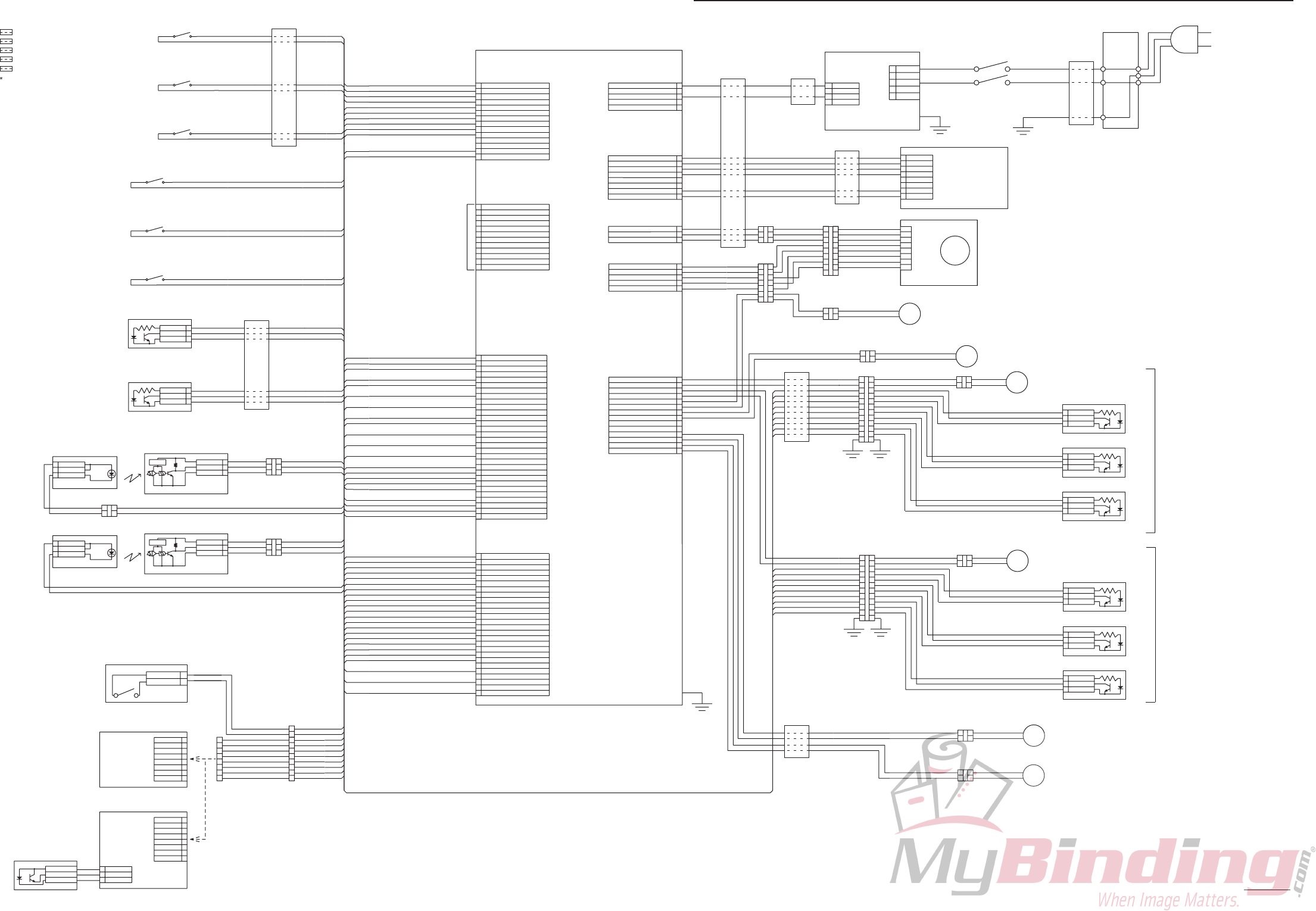
12H-M12M0-0309-0
2-33
8. OVERALL SCHEMATIC DIAGRAM (DF-920)
FE1
FE5
FE2
FE1
FE1
FE4
FE3
FE1
FE2
FE3
FE4
FE5
(2turn) : Toroidal clamp core 052-10065
(2turn) : Clamp filter 052-10052
(1turn) : Ferrite core 052-10027
(1turn) : Ferrite core 052-10035
(1turn) : Ferrite core 052-10035
F1 to F5 on a circuit diagram are one piece, respectively
FE1
Attach a PWB shielding cover
507 PURPLE
508 GRAY
510 GRAY
COM N.O.
054-10115
COM N.O.
054-10248
COM N.O.
054-10248
514 GRAY
98R-8023 3
ANODE
2
GND
COLLECTOR
1
FRONT COVER SW
98R-8023 3
ANODE
2
GND
COLLECTOR
1
305 BLUE
301 YELLOW
303 PINK
DELIVERY LIMIT SENSOR
1
2
3
4
5
6
7
8
9
10
11
12
J 01
PHD12T
TCK
GND
TDO
TMS
TXD
RXD
TDI
GND
MD1
FOR WRITING ON FPGA FLASH MEMORY
1
2
3
4
5
6
7
8
9
10
11
12
13
14
15
16
17
18
19
20
21
22
23
24
25
26
27
28
29
30
J03
PHD30T
1
2
3
4
5
6
7
8
9
10
11
12
13
14
15
16
17
18
19
J 04
20
21
22
23
24
25
26
ORIBAN1-INDEX1
ORIBAN1-INDEX2
GND
GND
ORIBAN2-INDEX1
ORIBAN2-INDEX2
GND
P-SEN1
P-SEN2
P-SEN3
P-SEN4
P-SEN5
P-SEN6
GND
ACSE2
REAR C
GND
GND
ORIKOMIBAN2-LIM
OUT-PA-SEN
OUT-PA-SEN
IN-PA-SEN
IN-PA-SEN
HAISIKORO-LIM
KYUDAI-PA-SEN
ORIKOMIBAN1-LIM
GND
GND
GND
GND
GND
GND
GND
GND
ACSE1
PHD26T
1
2
3
4
5
6
7
8
9
10
J 05
11
12
13
14
ORI1SET-1
ORI1SET-1
ORI1SET-2
ORI1SET-2
TOP C
TOP C
FRONT C
FRONT C
ACSE 3
KYUSI-SET
AUTO-LOW
EH14T
501 PURPLE
502 GRAY
503 SKYBLUE
504 GRAY
505 YELLOW
506 GRAY
507 PURPLE
508 GRAY
510 GRAY
514 GRAY
301 YELLOW
302 SKYBLUE
303 PINK
305 BLUE
306 BLUE
310 PINK
312 BLUE
315 PINK
317 BLUE
321 PINK
323 BLUE
324 BLUE
327 PINK
329 BLUE
330 BLUE
313 YELLOW
308 SKYBLUE
GND
GND
GND
N.C.
NC
+5V
+5V
+5V
AUTOMATIC-UP-SEN
+5V
+5V
GND
NC
+5V
+5V
GND
+5V
NC
+5V
+5V
+5V
+5V
GND
+5V
+5V
+5V
+5V
322 YELLOW
328 SKYBLUE
401 YELLOW
402 SKYBLUE
403 PINK
404 PINK
405 BLUE
406 BLUE
407 GRAY
409 PINK
410 PINK
411 BLUE
412 BLUE
413 PINK
414 YELLOW
416 GRAY
415 SKYBLUE
408 PURPLE
417 PURPLE
418 YELLOW
419 SKYBLUE
420 BLUE
422 SKYBLUE
426 BLUE
STARTING POINT SENSOR (UP)
STARTING POINT SENSOR (DOWN)
1
2
3
4
+24V
+24V
FG
VH05T
J 06
5
601 BROWN
603 BLUE
GND
GND
1
2
3
4
5
6
7
8
SDA
XH08T
SCL
GND
GND
GND
J 02
202 BLUE
204 BLUE
207 ORANGE
208 BLUE
201 PURPLE
203 GRAY
1
2
3
4
5
6
7
8
CN1
SDA
GND
202 BLUE
204 BLUE
207 ORANGE
208 BLUE
201 PURPLE
203 GRAY
12H-8006
OP UNIT
12H-8032
OP CIRCUIT DIAGRAM
J 09 1
2
3
1
2
3
4
5
J 07
GND
HW
HU
HV
VH03T
EH05T
22
1
3
1
3
901 GRAY
902 PURPLE
701 PINK
702 BLUE
703 PURPLE
704 YELLOW
705 SKYBLUE
MOT1
4
5
6
7
8
4
5
6
7
8
22
1
3
1
3
4
5
6
7
4
5
6
7
22
1
3
1
3
24V 3 8A
MOT4
96V-8146
1
21
2
BLUE
PURPLE
GRAY
YELLOW
GREEN
RED
ORANGE
99
U
V
W
GND
HE1
HE2
HE3
GRAY
SKYBLUE
PINK
BLUE
YELLOW
PURPLE
24V 83mA
Vcc
12H-8101
1
2
3
4
5
6
7
8
9
0
1
2
3
4
M2+
M2–
M3+
M3–
M4+
M4–
COUNTER
CLH1
CLH2
MOT5
1
21
2
J 08
3
4
5
6
7
8
3
4
5
6
7
899
1212
3
4
5
6
7
8
3
4
5
6
7
899
22
3
ANODE
98R-8023
1
COLLECTOR
2
GND
3
ANODE
98R-8023
1
COLLECTOR
2
GND
ANODE
1
COLLECTOR
GND
EH14T
811 BROWN
812 SKYBLUE
813 BROWN
3
ANODE
98R-8023
1
COLLECTOR
2
GND
3
ANODE
98R-8023
1
COLLECTOR
2
GND
ANODE
1
COLLECTOR
GND
802 SKYBLUE
804 YELLOW
806 PURPLE
808 GRAY
814 YELLOW
062-10782
062-10782
802 SKYBLUE
804 YELLOW
2
3
2
3
ORANGE
YELLOW
GREEN
BLUE
PURPLE
GRAY
WHITE
SKYBLUE
1
21
2
YELLOW
ORANGE
GREEN
PURPLE
BLUE
GRAY
WHITE
1
21
2
YELLOW
ORANGE
GREEN
PURPLE
BLUE
GRAY
WHITE
97J-8505
24V 230mA
0
1
1
2
BLACK
PINK
RED
ORANGE
YELLOW
GREEN
BLUE
PURPLE
GRAY
WHITE
SKYBLUE
BLACK
PINK
RED
10
11
1
2
1
2
10
11
1
2
0
1
WHITE
RED
RED
BLACK
BLACK
FG
PURPLE
BROWN
BROWN
BLACK
BROWN
BROWN
BROWN
RED
BROWN
+24V
+24V
+5V
M1U
M1V
M1W
+6 5V
SCL
GND
GND
+6.5V
GND
NC
DC BL MOTOR
RED
801 YELLOW
YELLOW
803 PURPLE
805 GRAY
807 SKYBLUE
807 SKYBLUE
808 GRAY
801 YELLOW
803 PURPLE
12H-8111
12H-8111
24V 160mA
24V 160mA
SKYBLUE
SKYBLUE
M5+
M5–
+24V
401 YELLOW
403 PINK
405 BLUE
402 SKYBLUE
404 PINK
406 BLUE
308 SKYBLUE
310 PINK
312 BLUE
407 GRAY
409 PINK
411 BLUE
408 PURPLE
410 PINK
313 YELLOW
315 PINK
317 BLUE
412 BLUE
HOME SENSOR
HOME SENSOR
DC MOTOR
DC MOTOR
PAPER FEED PLATE MOTOR
12H-8003
MC UNIT
12H-8301
MC CIRCUIT DIAGRAM
413 PINK
414 YELLOW
415 SKYBLUE
416 GRAY
417 PURPLE
418 YELLOW
419 SKYBLUE
420 BLUE
STOPPER MOVEMENT SENSOR (ENCODER) A
STOPPER MOVEMENT SENSOR (ENCODER) B
STOPPER MOVEMENT SENSOR (ENCODER) A
STOPPER MOVEMENT SENSOR (ENCODER) B
BROWN
MOTOR FOR MOVING STACKER ROLLER
319 GRAY
325 YELLOW
1
21
2
CLH1
811 BROWN
812 SKYBLUE BLUE
BLUE
FEEDING CLUTCH
1
21
2
813 BROWN
814 YELLOW BLUE
BLUE
CLH2
DELIVERY CLUTCH
24V 250mA 96Ω
24V 250mA 96Ω
SECOND FOLDING PLATE
FIRST FOLDING PLATE
MOT2
MOT3
424 PINK
SIDE COVER SW
424 PINK
422 SKYBLUE
426 BLUE
AC (N)
5
4
3
2
1
FG
SWITCHING POWER SUPPLY
CN1
057-10033
AC (L)
FG
CN2
4+24V
3+24V
2GND
1GND
BLACK
WHITE
GREEN/YELLOW
054-10308
BLACK
WHITE
POWER SW
AC (L)
AC (N)
FG
230V 10A
INLET
056-10357
AC220 to 240V 50/60Hz : 055-10212
POWER CORD
AC120V 60Hz : 055-10209
COM N.O. 501 PURPLE
502 GRAY
503 SKYBLUE
504 GRAY
505 YELLOW
506 GRAY
054-10115
COM N.O.
054-10115
COM N.O.
054-10115
TOP COVER SW
FOLDING PLATE SW1
FOLDING PLATE SW2
1
2
GND
1
2
3
4
5
6
7
8
SEN1
+5V
SEN2
SEN3
SEN4
SEN5
SEN6
96V-8016
96V-8018
PS P.W.B. UNIT
PS CIRCUIT DIAGRAM
UK Spec.
GND
1
2
3
4
5
6
7
8
SEN1
+5V
SEN2
SEN3
SEN4
SEN5
SEN6
96V-8026
96V-8028
PS P.W.B. UNIT
PS CIRCUIT DIAGRAM
USA Spec.
It changes by Spec.
1
2
3
96V-8110
PAPER SENSOR
ANODE
GND
PINK
WHITE
BLUE
+5V
PS1
CATHODE
EMITTER
4
5
6
7
8
2
1
3
1
2
GND
SIG (N O )
054-10326 PAPER SENSOR
1
2
1
21
2
3
1
2
3
11G-8052
11G-8052
BLUE
324 BLUE
FEED SENSOR FEED SENSOR
DELIVERY SENSOR DELIVERY SENSOR
PINK
BLUE
PINK
BLUE
11G-8051 1
2
3GND
Vcc
VOUT
C.V.C
11G-8051 1
2
3GND
Vcc
VOUT
C.V.C
ANODE
ANODE
ANODE
ANODE
CATHODE
CATHODE
SKYBLUE 330 BLUE
328 SKYBLUE
322 YELLOW
1
2
3
1
2
3
1
2
33
2
1
GRAY 321 PINK
323 BLUE
319 GRAY
YELLOW 327 PINK
329 BLUE
325 YELLOW
PINK
YELLOW
SKYBLUE
GRAY
PURPLE
YELLOW
SKYBLUE
BLUE
BLUE
SKYBLUE
SKYBLUE
BLUE
3
4
5
6
7
8
9
10
302 SKYBLUE
306 BLUE
509 BLUE
513 BLUE
509 BLUE
513 BLUE
903 SKYBLUE
SKYBLUE
PURPLE
12H-85101
12H-8120
12H-8168
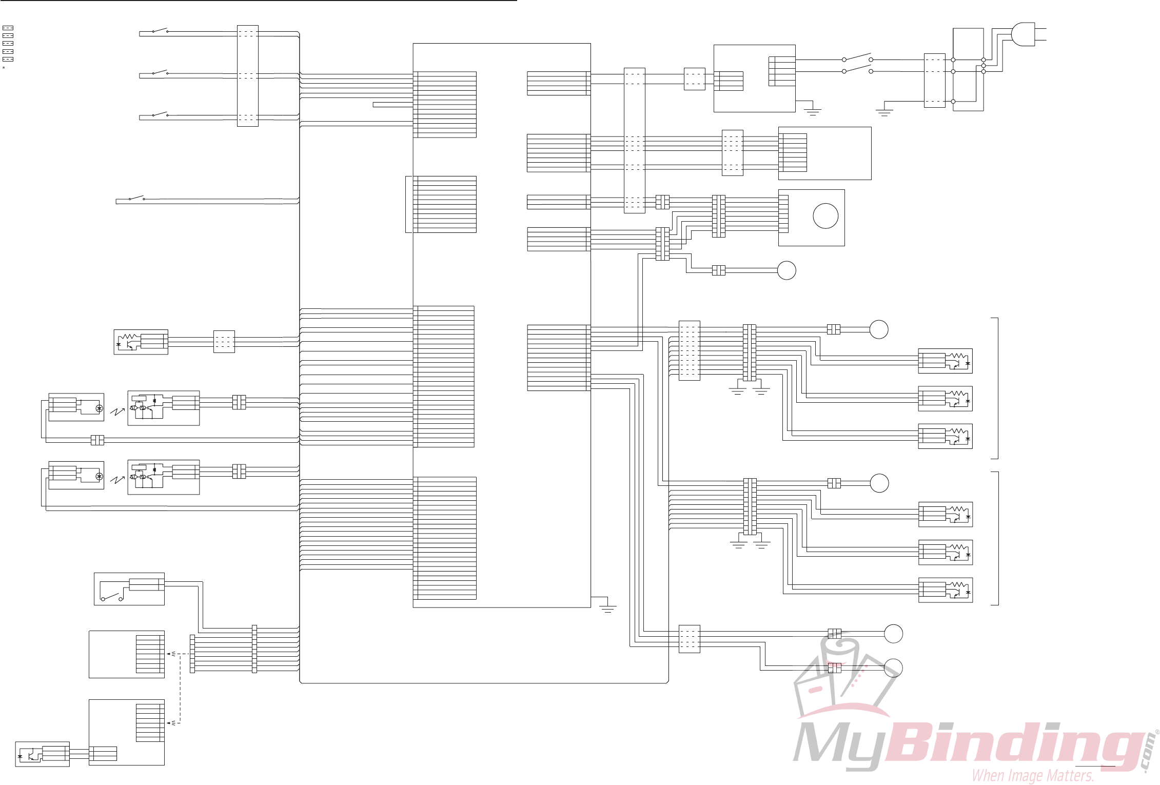
12H-M12M0-0309-0
2-34
9. OVERALL SCHEMATIC DIAGRAM (DF-915)
FE1
FE2
FE3
FE4
FE5
FE1
FE5
FE2
FE1
FE1
FE4
FE3
FE1
(2turn) : Toroidal clamp core 052-10065
(2turn) : Clamp filter 052-10052
(1turn) : Ferrite core 052-10027
(1turn) : Ferrite core 052-10035
(1turn) : Ferrite core 052-10035
F1 to F5 on a circuit diagram are one piece, respectively
Attach a PWB shielding cover
COM N.O.
98R-8023 3
ANODE
2
GND
COLLECTOR
1
305 BLUE
301 YELLOW
303 PINK
DELIVERY LIMIT SENSOR
1
2
3
4
5
6
7
8
9
0
1
2
J 01
PHD12T
TCK
GND
TDO
TMS
TXD
RXD
TDI
GND
MD1
FOR WRITING ON FPGA FLASH MEMORY
1
2
3
4
5
6
7
8
9
0
1
2
3
4
5
6
7
8
9
20
21
22
23
24
25
26
27
28
29
30
J03
PHD30T
1
2
3
4
5
6
7
8
9
0
1
2
3
4
5
6
7
8
9
J 04
20
21
22
23
24
25
26
ORIBAN1-INDEX1
ORIBAN1-INDEX2
GND
GND
ORIBAN2-INDEX1
ORIBAN2-INDEX2
GND
P-SEN1
P-SEN2
P-SEN3
P-SEN4
P-SEN5
P-SEN6
GND
ACSE2
REAR C
GND
GND
ORIKOMIBAN2-LIM
OUT-PA-SEN
OUT-PA-SEN
IN-PA-SEN
IN-PA-SEN
HAISIKORO-LIM
KYUDAI-PA-SEN
ORIKOMIBAN1-LIM
GND
GND
GND
GND
GND
GND
GND
GND
ACSE1
PHD26T
1
2
3
4
5
6
7
8
9
0
J 05
1
2
3
4
ORI1SET-1
ORI1SET-1
ORI1SET-2
ORI1SET-2
TOP C
TOP C
FRONT C
FRONT C
ACSE 3
KYUSI-SET
AUTO-LOW
EH14T
501 PURPLE
502 GRAY
503 SKYBLUE
504 GRAY
505 YELLOW
506 GRAY
301 YELLOW
302 SKYBLUE
303 PINK
305 BLUE
306 BLUE
310 PINK
312 BLUE
315 PINK
317 BLUE
321 PINK
323 BLUE
324 BLUE
327 PINK
329 BLUE
330 BLUE
313 YELLOW
308 SKYBLUE
GND
GND
GND
N.C.
NC
+5V
+5V
+5V
AUTOMATIC-UP-SEN
+5V
+5V
GND
NC
+5V
+5V
GND
+5V
NC
+5V
+5V
+5V
+5V
GND
+5V
+5V
+5V
+5V
322 YELLOW
328 SKYBLUE
401 YELLOW
402 SKYBLUE
403 PINK
404 PINK
405 BLUE
406 BLUE
407 GRAY
409 PINK
410 PINK
411 BLUE
412 BLUE
413 PINK
414 YELLOW
416 GRAY
415 SKYBLUE
408 PURPLE
417 PURPLE
418 YELLOW
419 SKYBLUE
420 BLUE
1
2
3
4
+24V
+24V
FG
VH05T
J 06
5
601 BROWN
603 BLUE
GND
GND
1
2
3
4
5
6
7
8
SDA
XH08T
SCL
GND
GND
GND
J 02
202 BLUE
204 BLUE
207 ORANGE
208 BLUE
201 PURPLE
203 GRAY
1
2
3
4
5
6
7
8
CN1
SDA
GND
202 BLUE
204 BLUE
207 ORANGE
208 BLUE
201 PURPLE
203 GRAY
12H-8006
OP UNIT
12H-8032
OP CIRCUIT DIAGRAM
J 09 1
2
3
1
2
3
4
5
J 07
GND
HW
HU
HV
VH03T
EH05T
2 2
1
3
1
3
901 GRAY
902 PURPLE
701 PINK
702 BLUE
703 PURPLE
704 YELLOW
705 SKYBLUE
MOT1
4
5
6
7
8
4
5
6
7
8
2 2
1
3
1
3
4
5
6
7
4
5
6
7
2 2
1
3
1
3
24V 3.8A
MOT4
96V-8146
1
21
2
BLUE
PURPLE
GRAY
YELLOW
GREEN
RED
ORANGE
99
U
V
W
GND
HE1
HE2
HE3
GRAY
SKYBLUE
PURPLE
24V 83mA
Vcc
12H-8101
1
2
3
4
5
6
7
8
9
10
11
12
13
14
M2+
M2–
M3+
M3–
M4+
M4–
COUNTER
CLH1
CLH2
J 08
3
4
5
6
7
8
3
4
5
6
7
899
22
3
4
5
6
7
8
3
4
5
6
7
899
1212
3
ANODE
98R-8023
1
COLLECTOR
2
GND
3
ANODE
98R-8023
1
COLLECTOR
2
GND
ANODE
1
COLLECTOR
GND
EH14T
811 BROWN
812 SKYBLUE
3
ANODE
98R-8023
1
COLLECTOR
2
GND
3
ANODE
98R-8023
1
COLLECTOR
2
GND
ANODE
1
COLLECTOR
GND
802 SKYBLUE
804 YELLOW
806 PURPLE
062-10782
062-10782
802 SKYBLUE
804 YELLOW
2
3
2
3
ORANGE
YELLOW
GREEN
BLUE
PURPLE
GRAY
WHITE
SKYBLUE
1
21
2
YELLOW
ORANGE
GREEN
PURPLE
BLUE
GRAY
WHITE
1
21
2
YELLOW
ORANGE
GREEN
PURPLE
BLUE
GRAY
WHITE
10
11
1
2
BLACK
PINK
RED
ORANGE
YELLOW
GREEN
BLUE
PURPLE
GRAY
WHITE
SKYBLUE
BLACK
PINK
RED
0
1
1
2
1
2
0
1
1
2
10
11
RED
RED
BLACK
BLACK
FG
PURPLE
BROWN
BROWN
BLACK
BROWN
BROWN
RED
BROWN
+24V
+24V
+5V
M1U
M1V
M1W
+6 5V
SCL
GND
GND
+6 5V
GND
NC
DC BL MOTOR
RED
801 YELLOW
YELLOW
803 PURPLE
805 GRAY
801 YELLOW
803 PURPLE
12H-8111
12H-8111
24V 160mA
24V 160mA
SKYBLUE
SKYBLUE
M5+
M5–
+24V
401 YELLOW
403 PINK
405 BLUE
402 SKYBLUE
404 PINK
406 BLUE
308 SKYBLUE
310 PINK
312 BLUE
407 GRAY
409 PINK
411 BLUE
408 PURPLE
410 PINK
313 YELLOW
315 PINK
317 BLUE
412 BLUE
HOME SENSOR
HOME SENSOR
DC MOTOR
DC MOTOR
12H-8003
MC UNIT
12H-8301
MC CIRCUIT DIAGRAM
413 PINK
414 YELLOW
415 SKYBLUE
416 GRAY
417 PURPLE
418 YELLOW
419 SKYBLUE
420 BLUE
STOPPER MOVEMENT SENSOR (ENCODER) A
STOPPER MOVEMENT SENSOR (ENCODER) B
STOPPER MOVEMENT SENSOR (ENCODER) A
STOPPER MOVEMENT SENSOR (ENCODER) B
BROWN
MOTOR FOR MOVING STACKER ROLLER
319 GRAY
325 YELLOW
1
21
2
CLH1
811 BROWN
812 SKYBLUE BLUE
BLUE
FEEDING CLUTCH
24V 250mA 96Ω
GRAY
813 BROWN
814 YELLOW
1
21
2
813 BROWN
814 YELLOW BLUE
BLUE
CLH2
DELIVERY CLUTCH
24V 250mA 96Ω
512 GRAY
512 GRAY
054-00396
PAPER FEED PLATE SET SW
12H-8120
12H-8168
1
2
1
21
2
3
1
2
3
11G-8052
11G-8052
BLUE
324 BLUE
FEED SENSOR FEED SENSOR
DELIVERY SENSOR
PINK
BLUE
PINK
BLUE
11G-8051 1
2
3
GND
Vcc
VOUT
C.V.C
11G-8051 1
2
3
GND
Vcc
VOUT
C.V.C
ANODE
ANODE
ANODE
ANODE
CATHODE
CATHODE
SKYBLUE 330 BLUE
328 SKYBLUE
322 YELLOW
1
2
3
1
2
3
1
2
33
2
1
GRAY 321 PINK
323 BLUE
319 GRAY
YELLOW 327 PINK
329 BLUE
325 YELLOW
DELIVERY SENSOR
1
2
GND
SIG (N O )
054-10326 PAPER SENSOR
GND
1
2
3
4
5
6
7
8
SEN1
+5V
SEN2
SEN3
SEN4
SEN5
SEN6
96V-8016
96V-8018
PS P.W.B. UNIT
PS CIRCUIT DIAGRAM
UK Spec.
GND
1
2
3
4
5
6
7
8
SEN1
+5V
SEN2
SEN3
SEN4
SEN5
SEN6
96V-8026
96V-8028
PS P.W.B. UNIT
PS CIRCUIT DIAGRAM
USA Spec.
It changes by Spec.
1
2
3
96V-8110
PAPER SENSOR
PINK
WHITE
BLUE
+5V
PS1
CATHODE
ANODE
GND
EMITTER
1
2
3
4
5
6
7
8
2
1
3
PINK
YELLOW
SKYBLUE
GRAY
PURPLE
YELLOW
SKYBLUE
BLUE
BLUE
SKYBLUE 1
2302 SKYBLUE
306 BLUE
3
4
5
6
7
8
9
0
903 YELLOW
PINK
BLUE
YELLOW
SKYBLUE
PURPLE
FIRST FOLDING PLATE
SECOND FOLDING PLATE
MOT3
MOT2
AC (N)
5
4
3
2
1
FG
SWITCHING POWER SUPPLY
CN1
057-10033
AC (L)
FG
CN2
4+24V
3+24V
2GND
1GND
BLACK
WHITE
054-10308
BLACK
WHITE
POWER SW
AC (L)
AC (N)
FG
230V 10A
INLET
056-10357
AC220 to 240V 50/60Hz : 055-10212
POWER CORD
AC120V 60Hz : 055-10209
COM N.O. 501 PURPLE
502 GRAY
503 SKYBLUE
504 GRAY
505 YELLOW
506 GRAY
054-10115
COM N.O.
054-10115
COM N.O.
054-10115
TOP COVER SW
FOLDING PLATE SW1
FOLDING PLATE SW2
GREEN/YELLOW
SKYBLUE
BLUE
511 BLUE
511 BLUE
12H-85201
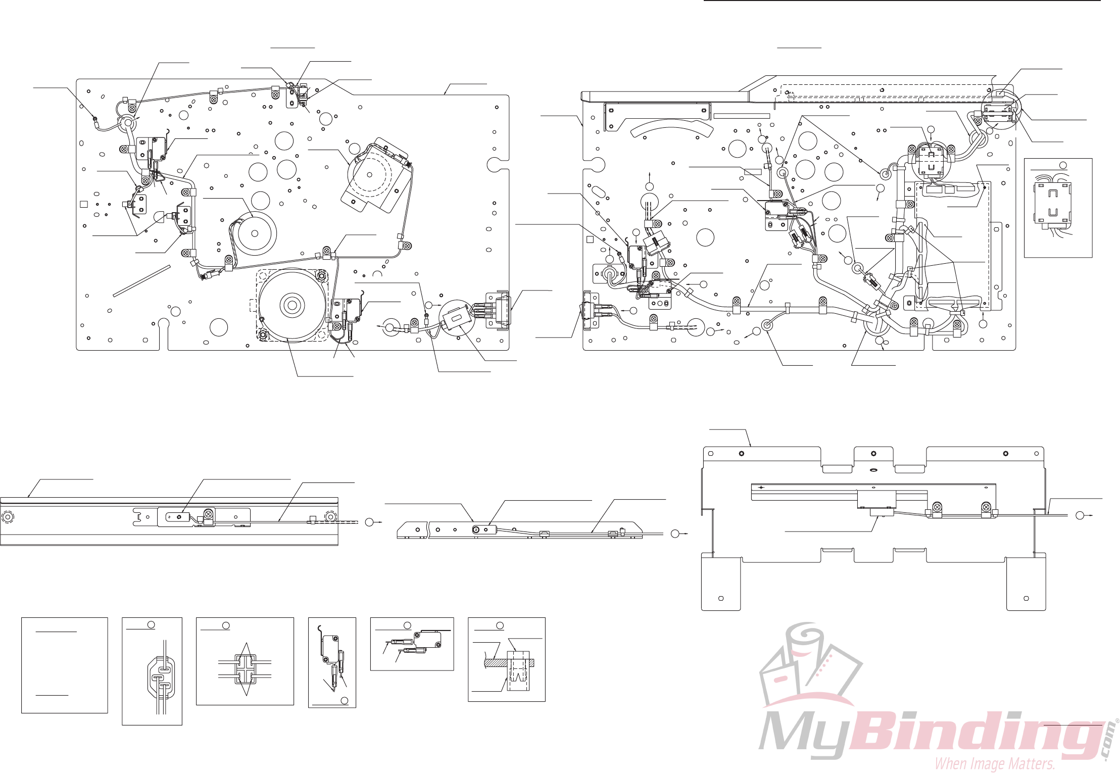
12H-M12M0-0309-0
2-35
10. WIRING DIAGRAM 1/2 (DF-920)
Brass screw
M4 toothed lock washer
View of A
2 turns
052-10052
Clamp ilter
Details for F
056-00778
Bush
056-00779
Collar
12H-8101
Brushless DC motor
Brass screw
M4 toothed
lock washer
Details for E
12H-8208
Bundled wire unit 8
12H-8201
920 bundled
wire unit 1
12H-8206
Bundled wire
unit 6
12H-8207
Bundled wire
unit 7
056-00003
Bushing
(OCB-500)
5N
Purple
Yellow
056-00876
SK binder
056-00876
SK binder
View of G
12H-8605
OP P.W.B. unit
Gray
Gray
056-00003
Bushing
(OCB-500)
056-00644
Bushing
(OCB-875)
Light blue
Gray
054-10248
Microswitch
5N
3N
4N
4N
2N
2N
3N
6N 5N
5N
054-10248
Microswitch
Main frame F
12H-5003
Main frame F
056-00876
SK binder
12D-8703
Universal bush
11G-8051
Separation type photointerrupter
12H-8206
Bundled wire unit 6
2N2N
12H-4004
Stacker plate
054-10115
Microswitch
054-10308
Power switch
056-00003
Bushing
(OCB-500)
6N
056-00778
Bush x 3
12H-5008
Main frame B
Main frame B
054-10115
Microswitch
3N
2N
98R-8023
Photointerrupter
12H-8120
Paper feed
clutch unit
3N
056-00644
Bushing
(OCB-875)
7N
Purple
4N
056-00876
SK binder
Gray
Light blue
Gray
054-10115
Microswitch
056-00779
Collar x 3
6N
12H-8003
MC unit
5N
Cable clamp
2N 056-09001 3302
3N 056-09002 3303
4N 056-09003 3304
5N 056-09004 3305
6N 056-09005 3306
7N 056-09006 3307
Cable clip
Middle 056-07008 1197
L
Green/Yellow Black
White
N
E
12H-8212
Bundled wire unit 11
056-10357
Inlet
12H-8211
Bundled wire unit 10
1 turn
052-10035
Ferrite core
12H-8205
Bundled wire unit 5
1 turn
12H-8003
MC unit
052-10027
Ferrite core
2N
12H-2533
Lower sensor angle
2N
2N 2N
4N
4N
3N
2N 2N
12H-8168
Paper ejection
clutch unit
Yellow
Gray
12H-5333
Switch angle T
054-10248
Microswitch
3N
056-10100
Spacer
3N
2N 2N
12H-2525
Paper feed inlet upper guide
11G-8052
Separation type photointerrupter
11G-8051
Separation type photointerrupter
12H-8208
Bundled wire unit 8
Details for H
12H-8207
Bundled wire unit 7
Fix the ferrite core with
the binder provided.
056-00876
SK binder
6N
056-00876
SK binder
B
i
h
g
k
d
E
F
c
ef
jl
i
jh
A
G
TDK
MEC
a
b
H
TDK
12H-85010 (1/2)
12H-8201
920 bundled wire unit 1
Brass screw
M4 toothed lock washer
24
3
Insulating sleeve (Blue)
Insulating sleeve (Green)
White
White
View of B
Black
Black
1

12H-M12M0-0309-0
2-36
11. WIRING DIAGRAM 2/2 (DF-920)
12H-8201
920 bundled
wire unit 1
054-10326
Detection switch
12H-8211
Bundled wire unit 10
12H-8201
920 bundled
wire unit 1
052-10065
Toroidal clamp
core
056-00876
SK binder
052-10035
Ferrite core
2 turns
12H-5065
Power supply base
12H-8101
Brushless DC motor
12H-8205
Bundled wire unit 5
1 turn
056-00876
SK binder
12H-2004
Paper feed tray
5N 5N
96V-8026
PS P.W B. unit
11G-8052
Separation type photointerrupter
056-00003
Bushing
(OCB-500)
5N
5N5N
2N
2N
056-00644
Bushing
(OCB-875)
056-00644
Bushing
(OCB-875)
056-00876
SK binder
2N
View of I
3N
12H-9074
Paper feed tray lower cover
12H-2004
Paper feed tray
12H-5003
Main frame F
12H-3003
Folding plate 1
062-10782
Photointerrupter
056-00003
Bushing
(OCB-500)
98R-8023
Photointerrupter
12H-8111
DC motor unit
12H-8202
Bundled wire unit 2
12H-8111
DC motor unit
98R-8023
Photointerrupter
056-00003
Bushing
(OCB-500)
12H-8203
Bundled wire unit 3
062-10782
Photointerrupter
12H-3203
Folding plate 2
056-00876
SK binder
054-10326
Detection switch
12H-8211
Bundled wire unit 10
12H-2004
Paper feed tray
5N 5N
96V-8016
PS P.W B. unit
USA specifications
UK specifications
12H-8209
Bundled
wire unit 9
Middle
Middle
96V-8146
DC motor
2N
056-00003
Bushing
(OCB-500)
97J-8505
DC motor unit
12H-5008
Main frame B
057-10033
Switching power supply
12H-2404
Auxiliary paper feed tray
96V-8110
Photointerrupter
12H-9034
Bracket
12H-9034
Bracket
056-10322
Bushing
(OCB-562)
3N
056-10322
Bushing
(OCB-562)
3N
12H-8209
Bundled wire unit 9
Blue/Purple/GrayOrange/Yellow/Green
98R-8023
Photointerrupter
View of C D
056-10100
Spacer x 5
Middle
12H-8204
Bundled wire unit 4
Middle
12H-5016
Reinforcement plate L
Middle
Middle
Middle
12H-8209
Bundled wire unit 9
c
k
m
l
a
d
m
n
D
C
I
n
c
e
f
g
n
n
b
MEC
12H-85010 (2/2)
Brass screw
M4 toothed lock washer
Brass screw
M4 toothed lock washer
USA specifications
USA specifications
Main reinforcement
base
12H-5024
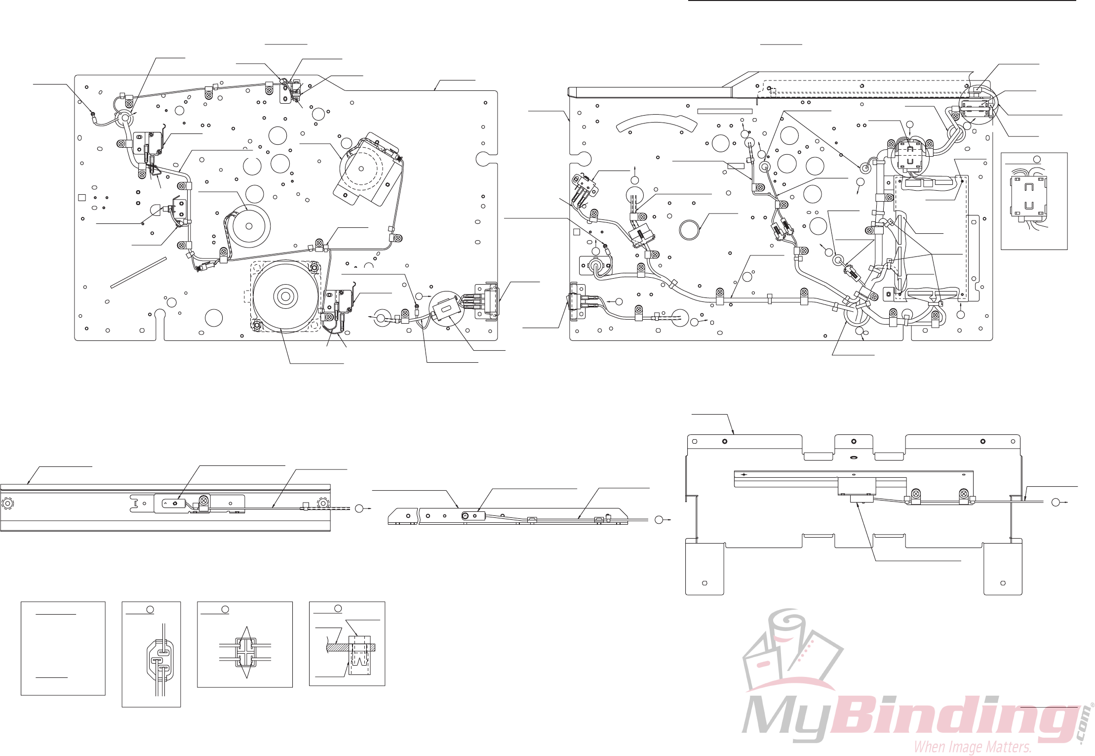
12H-M12M0-0309-0
2-37
12. WIRING DIAGRAM 1/2 (DF-915)
12H-8004
OP P.W B. unit
052-10052
Clamp filter
Brass screw
M4 toothed
lock washer
12H-8208
Bundled wire unit 8
12H-8221
91X bundled
wire unit 1
2N
B
2 turns
h
g
f
12H-8206
Bundled
wire unit 6
12H-8207
Bundled
wire unit 7 056-00779
Collar x 3
056-00003
Bushing
(OCB-500)
j
5N
056-00876
SK binder
056-00778
Bush x 3
d
Gray
056-00003
Bushing
(OCB-500)
056-00644
Bushing
(OCB-875)
c
e
i
k
5N
3N
3N
4N
2N
2N
3N
6N 5N
5N
Main frame F
12H-5003
Main frame F
054-10308
Power switch
Brass screw
M4 toothed lock washer
7N
6N
6N
12D-8703
Universal bush
Purple
054-10115
Microswitch
12H-5008
Main frame B
Main frame B
054-10115
Microswitch
98R-8023
Photointerrupter
12H-8120
Paper feed
clutch unit
3N
056-00644
Bushing
(OCB-875)
4N
056-00876
SK binder
Light blue
Gray
12H-8205
Bundled wire unit 5
12H-8101
Brushless DC motor
056-10100
Spacer
056-00876
SK binder
E
056-10357
Inlet
2N
2N 2N
4N
4N
3N
2N 2N
2N
3N
12H-8168
Paper ejection
clutch unit
Yellow
Gray
a
b
12H-5333
Switch angle T
054-10248
Microswitch
052-10027
Ferrite core
6N 5N
3N
12H-8602
MC unit
052-10035
Ferrite core
1 turn
1 turn
12H-8211
Bundled wire unit 10
054-00396
Microswitch
056-00876
SK binder
12H-8212
Bundled wire unit 11
056-00876
SK binder
056-11299
Hole plug
3N
Blue Gray
A
F
TDK
MEC
Brass screw
M4 toothed lock washer
12H-8221
91X bundled wire unit 1
Cable clamp 056-00778
Bush
056-00779
Collar
View of E
L
24
3
12H-8602
MC unit
Insulating sleeve (Blue)
Insulating sleeve (Green)
White
Green/Yellow
White
View of A View of B
Black
White
Black
N
E
1Black
2N 056-09001 3302
3N 056-09002 3303
4N 056-09003 3304
5N 056-09004 3305
6N 056-09005 3306
7N 056-09006 3307
Cable clip
Middle 056-07008 1197
12H-8207
Bundled wire unit 7
12H-8208
Bundled wire unit 8
11G-8051
Separation type photointerrupter
11G-8052
Separation type photointerrupter
12H-2525
Paper feed inlet upper guide
2N
2N
11G-8051
Separation type photointerrupter
12H-8206
Bundled wire unit 6
2N2N
12H-4004
Stacker plate
12H-2533
Lower sensor angle
2N
i
h
g
12H-85020 (1/2)
Fix the ferrite core with
the binder provided.
Details for F
TDK
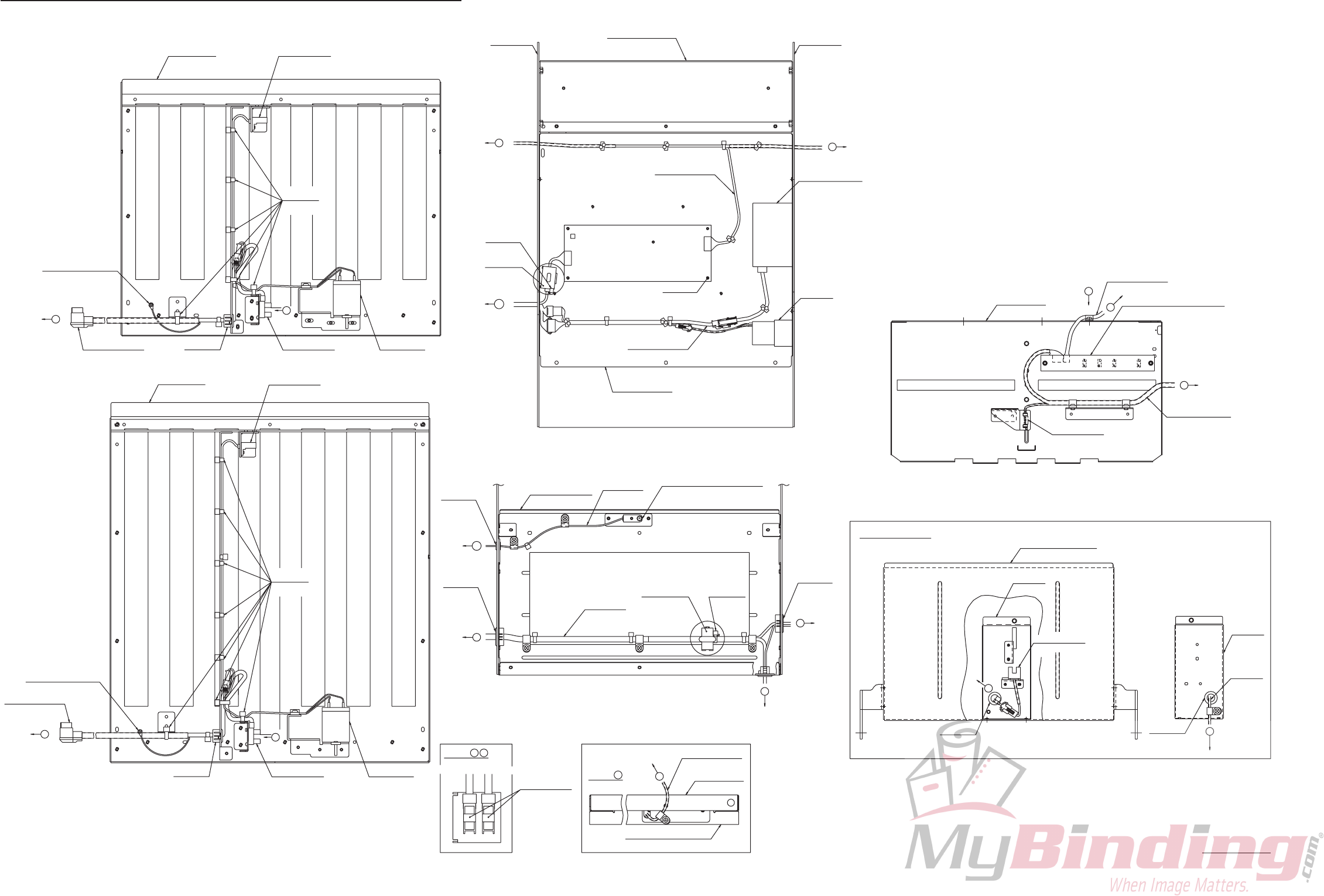
12H-M12M0-0309-0
2-38
13. WIRING DIAGRAM 2/2 (DF-915)
Brass screw
M4 toothed lock washer
12H-8221
91X bundled
wire unit 1
12H-8221
91X bundled
wire unit 1
052-10065
Toroidal clamp
core
056-00876
SK binder
12H-5065
Power supply base
12H-8101
Brushless DC motor
12H-8205
Bundled wire unit 5
1 turn
11G-8052
Separation type photointerrupter
Main reinforcement
base
12H-5024
056-00003
Bushing
(OCB-500)
5N
5N
5N
2N
2N
056-00644
Bushing
(OCB-875)
056-00644
Bushing
(OCB-875)
056-00876
SK binder
2N
2N
98R-8023
Photointerrupter
12H-5003
Main frame F
12H-3003
Folding plate 1 062-10782
Photointerrupter
056-00003
Bushing
(OCB-500)
98R-8023
Photointerrupter 12H-8111
DC motor unit
12H-8202
Bundled wire unit 2
Brass screw
M4 toothed lock washer
12H-8111
DC motor unit
98R-8023
Photointerrupter
056-00003
Bushing
(OCB-500)
12H-8203
Bundled wire unit 3
062-10782
Photointerrupter
12H-3203
Folding plate 2
056-00876
SK binder
056-00876
SK binder
2 turns
Middle
Middle
96V-8146
DC motor
12H-5008
Main frame B
057-10033
Switching power supply
056-10100
Spacer x 5
Middle
12H-8204
Bundled wire unit 4
Middle
12H-5016
Reinforcement plate L
Middle
Middle
Middle
052-10035
Ferrite core
j
l
k
a
d
lD
C
e
f
b
MEC
12H-85020 (2/2)
12H-9034
056-10322
Bushing
(OCB-562)
054-10326
Detection switch
3N
056-10322
Bushing
(OCB-562)
Bracket
12H-9034
Bracket
12H-2004
Paper feed tray
5N 5N
96V-8026 (USA), 96V-8016 (UK)
PS P.W.B. unit
96V-8110
Photointerrupter
12H-2404
Auxiliary paper feed tray
3N (USA)
12H-9074
Paper feed tray lower cover
12H-2004
Paper feed tray
USA specifications
12H-8211
Bundled wire unit 10
12H-8209 (USA)
Bundled wire unit 9
12H-8209
Bundled
wire unit 9
12H-8209 (USA)
Bundled wire unit 9
3N (USA)
m
m
c
m
G
m
Blue/Purple/GrayOrange/Yellow/Green
View of C D
View of G

12H-M12M0
