MyBinding Graphicwhizard 3000 12000 Service Manual User Graphic Whizard
2013-06-04
User Manual: MyBinding Graphicwhizard-3000-12000-Service-Manual
Open the PDF directly: View PDF ![]() .
.
Page Count: 49


21-2283 Argentia Road, Mississauga, Ontario Canada L5N 5Z2; Tel: (905) 858-7663 Fax :(905) 858-4419 Toll Free 1-8 00-265-3376
Website: www.graphicwhizard.com Email: contact@graphicwhizard
SERVICE MANUAL
VERSION 1.0

- 2 -
TABLE OF CONTENTS
Technical Highlights 3
1.0 Specifications 5
2.0 GW Junior 6
2.1 GW Junior Circuit Board Values 6
2.2 Troubleshooting 7
2.3 GW Junior Parts Diagram 7
3.0 GW 3000 Operation 8
3.1 Running a Job 8
3.2 Stopping a Job 8
3.3 Clearing a Job 9
3.4 Changing and Programming a Job 9
3.5 Error Codes 10
4.0 GW 6000 Operation 11
4.1 Running a Job 11
4.2 Stopping a Job 11
4.3 Clearing a Job 12
4.4 Changing and Programming a Job 12
4.5 Speed Control 13
4.6 GW 6000 Software Set-up and Diagnostics 13
4.7 Overview 13
4.8 Individual Items 14
4.9 GW 6000 Error Codes 17
5.0 GW 8/12000 Operation 18
5.1 Running a Job 18
5.2 Stopping a Job 20
5.3 Changing Programs 20
5.4 Programming a Job 21
5.5 The Batch Function 23
5.6 The Repeat Function 24
5.7 Motor Speed Control 24
5.8 GW 8/12000 Software Set-up and Diagnostics 25
5.9 Overview 25
5.10 Individual Items 25
5.11 GW 8/12000 Error Messages 29
6.0 Circuit Boards Layout and Diagnostics 30
6.1 GW 3/6000 Circuit 30
6.2 GW 8/12000 Circuit 31
6.3 GW 3/6/8/12000 Circuit Diagnostics 32
7.0 GW Parts List 38
8.0 Parts Diagrams 43
8.1 Feed Tray Assembly 43
8.2 Exit Tray Assembly 43
8.3 GW 3/6/8000 Operator Side 43
8.4 Electric Solenoid Drive Unit 44
8.5 Pneumatic Solenoid Drive Unit 44
8.6 Accessory Holder 45
8.7 Blade Placement on Boss Wheel 45
8.8 GW 12000 Feed Drive Components 45
8.9 GW 12000 Structural Parts Diagram 46
8.10 GW 3/6/8000 Shaft Placement 46
8.11 Conveyor Outfeed Assembly 47

- 3 -
TECHNICAL HIGHLIGHTS
Many of the benefits of our product design, construction, and materials details are not indicated in our product
literature. Obviously these details are important facts which are critical to a full understanding of our equipment
We build what we feel is the best equipment available. We take great pride and satisfaction in the knowledge that we
offer true value and performance to every customer. Our users consistently comment on the durability, ease of use
and versatility of their machines.
Their positive reactions are no accident. Listed below are the reasons.
< Feed System- we use a feed system on all our automatic machines unlike any other. The stock is fanned
forward so that the lead sheet only touches the feed tires. There is a complete lead edge retarding strip that will hold
back following sheets. We use three feed tires evenly spaced along the lead edge (the two outside tires 12" from the
edge of the stock and the third in the middle) of the page for a more consistent, straight paper feed. The pressure of
the feed tires needs only be enough that you feel a slight resistance between the stock and feed tires. This feed
system provides consistent feeding with drastically less problems of skewing, kicking, marking, scuffing and double
feeding of your stock.
< Head Driver- we are unique in the way we propel our numbering heads to the paper. We refer to it as inertia
drive. Whether using our solenoid or pneumatic drivers, there is no direct coupling of the numbering head and the
driver. The driver stroke is shorter than the head's travel to the paper. The driver has been specifically engineered to
produce rapid acceleration, impact the numbering head under inertia, and immediately release. With the inertia from
the driver, the numbering head is propelled to the paper, makes an impression on the paper and is free to return after
hitting the platen. The result is a clean and clear number. Think of it as throwing a ball against the wall and having it
bounce back rather than pushing the ball into the wall. The further benefit to this method is the reduced wear and tear
on the head frame, components, wheels etc. Resulting in longer head life.
Electronic Impression Control- microprocessor and digital control in all our models allow us to control, with
great precision, the time for which we energize our drive. This allows us to impart more or less inertia to the head
depending on how much of the stroke we energize for, thus controlling the strength of our numbering head crash.
Simply put, the longer we accelerate for, the faster we go, the harder we hit.
Solenoid Design- just look at one. The totally enclosed, tubular design creates the most efficient, complete
magnetic flux path providing the maximum energy output and optimum efficiency. The moving plunger is coated with
molybdenum disulphide, an anti friction coating used in jet airplane engines.
Numbering Head- the standard numbering head offered is an all steel numbering machine manufactured by
Reiner Gmbh & Co. in Germany. It has been our head of choice since the beginnings of our machine design ten years
ago and has proved so reliable that two of our competitors subsequently chose the same supplier's numbering head
for use in their machines.
Drive Unit Mount Assembly- thick, stiff and durable. The first of our many "never replaced due to a failure"
parts
Shafting- all the turning shafting in our products is made from a special high tensile strength steel which offers
the strength, rigidity, resistance to deflection, and a number of other critical mechanical properties normally available
only on shafting of significantly larger diameter. The shafting is supplied "centerless ground” to exacting
specifications measured at one half of one thousandth of an inch (0.0005"). Once machined to its final dimensions.
We straighten the shafting to within one thousandth over its length to ensure consistency and accuracy in perforating
scoring or slitting operations. The shafting is also plated with a very hard skin of chromium to prevent corrosion and
marking from setscrews. This shafting has proved so durable that we have never replaced a shaft on any unit
due to wear or fatigue.
Bushings- the shafts are supported in the machine and spin within oil impregnated bronze bushings. These
automatically release oil to the shafting as required. They are stressed in the unit at less than 30% of their rated load.
The bushings have proved so durable that we have not yet replaced one as failed in the field.

< Framework- once again we take the stand that, enough is not enough. As with the balance of the machine,
technical testing is carried out and the results used to choose materials. In this case, we use materials rated at triple
the rated requirements. We have never experienced the failure of a frame component. We tie all the parts
together with rigid cross shafts. On our two larger models, we weld the stand out of heavy section angle rather than
making it out of stamped thin steel. The result is quieter, more solid running equipment.
< Rollers- all are solid urethane. Impervious to cleaning chemistry, chemicals in the paper (such as the ones in
carbonless paper), and whatever else may contact them. They are also capable of being machined to more precise
tolerances, are more resistant to abrasion, and quite simply last longer. While we do encounter normally expected
wear on the feed tires, the main rollers are another of our "never replaced" parts.
< Electronics- so reliable we back them for five years (see our warranty for details). Enough said. If one
ever fails, the self-diagnostic features identify the problem and allow full details to the technician by phone. The
problem is immediately identified and correction can be carried out without requiring a service call. Exchanging the
circuit boards has also been made simple enough that a technician may not be required. Of course, with our network
of dealers across the country, help is never more than a phone call away.
< Drive Train- all drive components are metal. The main timing belt is steel reinforced. The motors are
brushless. All require no maintenance.
This listing could continue and provide you with every little detail we've sweated over while designing and building
your machine. We can (and will if you ask) tell you about gold plated contacts, idc type connectors, and a host of
other things. It's your right to know that you are getting your money's worth!
Our final word here is to tell you what we don't do. Quite simply, we don't add cosmetic features, which have no effect
on performance and add only to cost. We don't stand still and we continue to evolve the products based on
experience and field comments. We redesign with our existing customers in mind and make all future enhancements
retrofitable to the first machine we built. We don't run down our competitors and their products, we strive to stay a few
steps ahead of them. We know that if you really look you will recognize the value in our products.
We sincerely appreciate your interest and your time reading through this note.
Please contact your local dealer or us if you require any further details.
- 4 -

1.0 SPECIFICATIONS
GW Junior
Tabletop, footpedal operated numbering machine, standard forward head.
GW 3000
Programmable for a single hit per sheet per head, auto feed
numbering/perforating/scoring system, single speed of 3000 sheets per hour, maximum
of two numbering heads; optional conveyor outfeed and stand.
GW 6000
Programmable for up to 10 hits per sheet per head, auto feed
numbering/perforating/scoring system, three speeds of up to 6000 sheets per hour,
maximum of two numbering heads; optional conveyor outfeed and stand.
GW 8000
Programmable 100-job memory for up to 100 hits per sheet per head, auto feed
numbering/perforating/scoring system, batching capability, variable speeds of up to
8000 sheets per hour, maximum of four pneumatic numbering heads, optional conveyor
outfeed.
GW 12000
Programmable 100-job memory for up to 100 hits per sheet per head, auto feed
numbering/perforating/scoring system, batching capability, variable speeds of up to
12000 sheets per hour, maximum of four pneumatic numbering heads, conveyor
outfeed, optional air feed.
FinishMaster 100
Table top, autofeed perf/score/slit system, up to 10,000 sheets per hour, optional
conveyor outfeed and stand.
FinishMaster 150
Autofeed perf/score/slit system, up to 20,000 sheets per hour; optional air feed.
Paper weight: 12# - 12 point (45-250 gsm)
Paper formats: max. 18” x 18” (45 x 45 cm)
min. 3” x 5” (7.6 x 12.7 cm)
Electrical configuration:
Voltage: 90-135 VAC or
180-270 VAC
Frequency: 60 Hz or
50 Hz
- 5 -
Fusing: 115/250V, 3/5A
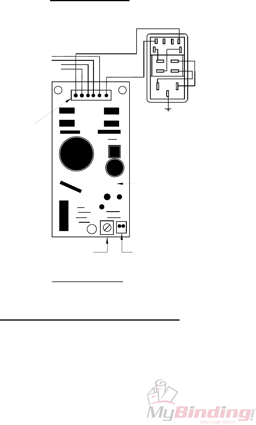
2.0 GW JUNIOR
2 Pin Impression
Control Connector
(harness: 20-015-GW)
6 Pin Connector
20-013-GW
MODULAR SWITCH
W/FUSEHOLDER
90-062-GW
SOLENOIDS
FOOTPEDAL
BLUE
BLUE
BROWN
25-012-GW
Impression Control
Potentiometer
Model J-1 Circuit Board
654
321
GREEN
BROWN
BLUE
2.1 GW Junior Circuit Board Values
On the Circuit Board (refer to diagram), there is a 6 Pin Main Connector (male). Numbering the
pins as follows, 6;5;4;3;2;1, from the wires you will have the following values:
1&6 -Power -you should then read the line voltage to the circuit (VAC).
2&3 -Footpedal -by pressing the footpedal, you will see the resistance change as
the line opens and closes.
4&5 -Solenoid -the solenoid resistance value will be approximately 40Ω (ohms).
On older machines, this value may range from 40 to 90Ω.
- 6 -
2.2 Troubleshooting
If you do not have a line voltage reading from pins 1&6, there is a break in the line and repairs are
required. First check the main fuse, then trace back the line for breaks.
If there is no resistance reading from the Solenoid, replacement is required of both the Solenoid and
Circuit Board. Once the Solenoid shorts, the Circuit Board will then have a short somewhere on the
real estate.
If there is no reading variation from the Footpedal, check the line for breaks. There may not be
correct contact at the Footpedal's contact point if there are no breaks in the line. Remove the two
side screws from the footpedal, but carefully because the top is sprung. The contact point will now
be exposed. There may be corrosion or dirt at the contact point. With very fine sandpaper, clean the
points reassemble and test. If after the above is performed and you still do not locate the problem,
the Footpedal may require replacement
In the bottom right of the Circuit Board is a 2 Pin Impression Control Connector. This connects to
the Impression Control on the Operating Panel. Make sure that the Impression Control is not
completely counter-clockwise, as this may close the circuit. As well, the Impression Control
Potentiometer on the circuit board is used to change the Impression Control range according to the
line voltage, and again it should not be fully counter-clockwise.
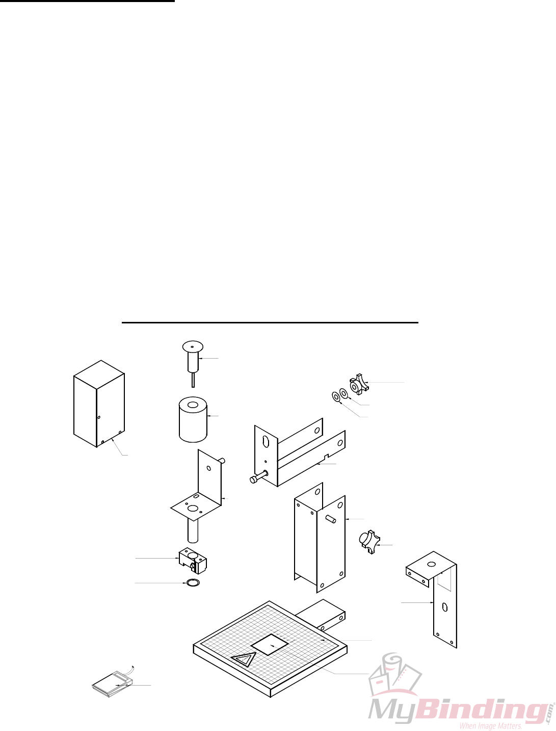
2.3 GW JUNIOR PARTS DIAGRAM
10-011-GW
10-054-GW
20-010-GW
10-053-GW
10-052-GW
10-043-GW
10-044-GW
25-009-GW
20-003-GW
20-002-GW
10-040-GW
10-040-GW
20-005-GW
25-004-GW
10-041-GW
10-042-GW
- 7 -

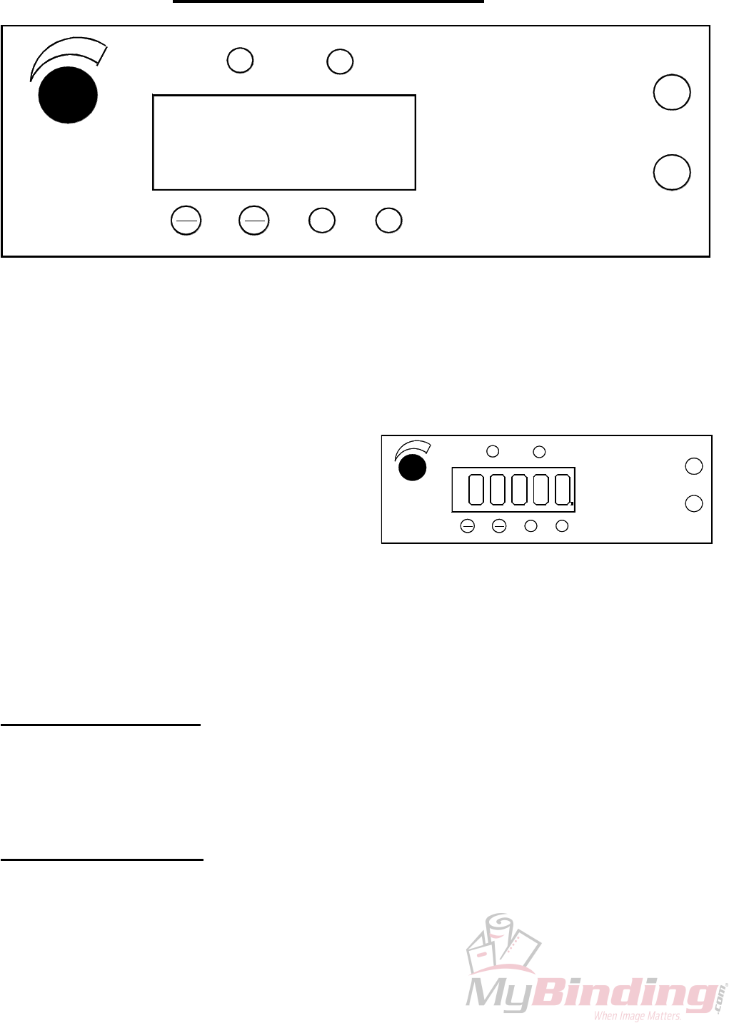
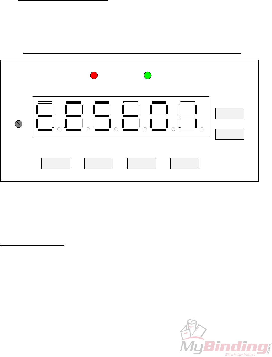
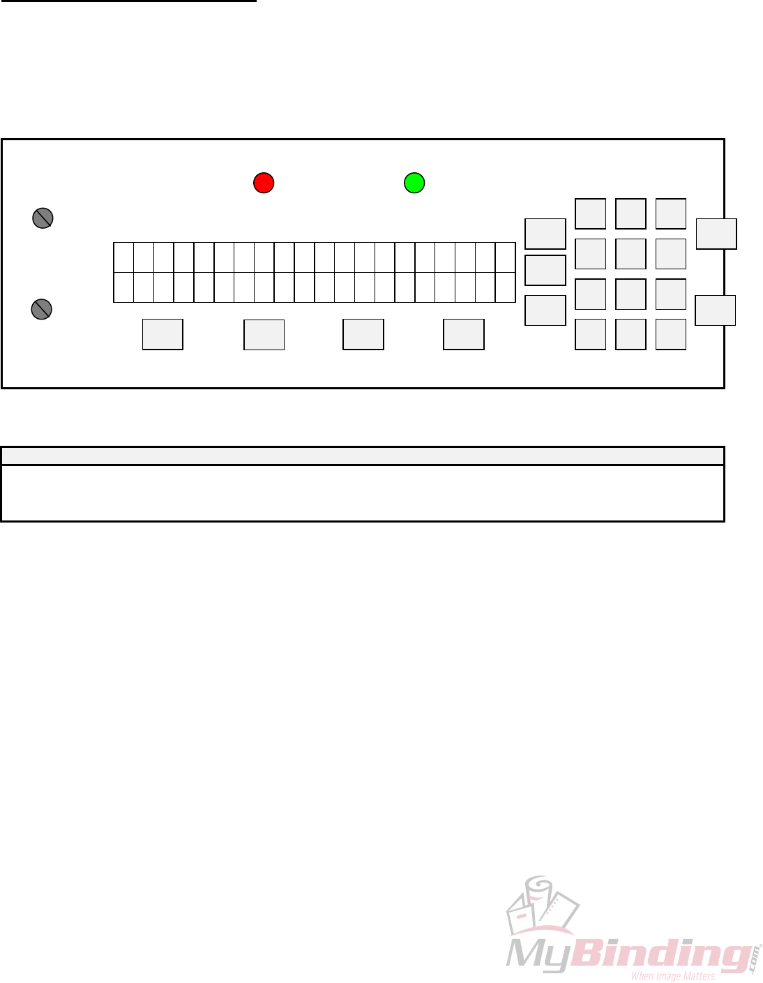
3.0 GW 3000 OPERATION
PHOTOCELL
IMPRESSION
CONTROL
SET
FWD CLR
BWD
H1
SAFETY
H2
STOP
START
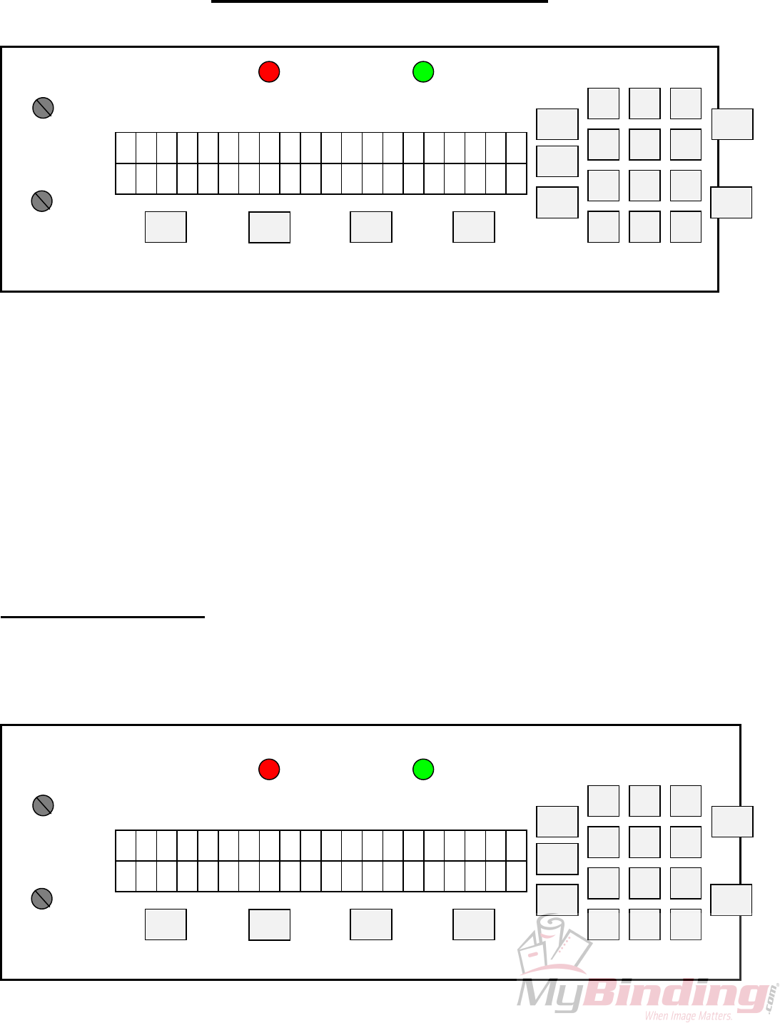
The operating keyboard is comprised of various buttons and a Impression Control which
consist of one potentiometer knobs that control the crash strength of the numbering heads, and can be
adjusted to best suit the requirements of the job. For example, you may require stronger crash
numbering for carbonless sets than for single sheet bond paper. This adjustment can be done while the
machine is stopped or running.
The four buttons under the LED display will perform whatever function is shown directly on them.
SET/FWD – Is used to set up a numbering job and incrementing the motor in a forward direction.
CLR/BWD- Is used to clear programs and increment the motor backwards.
H1- Is used to control head number one which is the head closest to the operator.
H2- Is used to control head number two which is the head furthest away from the operator.
START – Is used to start the machine.
STOP- Is used to stop the machine.
Once you have plugged the machine in, turn the on/off switch to the 'on' position. The LEDs
will flicker and then stop. The GW 3000 does systematic error checks, if it detects an error the LEDs
will remain flickering, count the number of flickers and compare with the list of all possible error
codes.
3.1 Running a Job
The machine is capable of storing a 1 job 1 hit for recall and future use. Ensure that there is
paper in the feed tray first. Pressing the 'START' button will automatically begin the program that was
previously programmed in the memory.
3.2 Stopping a Job
There are two methods of stopping the machine.
1. Once the program is running, pressing the 'STOP' button will cause the machine to finish the
stock it is currently working on, move the next stock into the starting position and then stop the
motor.
2. If you want to stop the machine while stock is still left in it, simply hold on to the stock in the
feed tray. After about one second, the machine will automatically stop (since it is no longer
seeing any new sheets). This is how it also stops when all of the stock in the feed tray is gone.
3. Pressing any of the other buttons will stop the machine defaulting the machine to its idle mode.
- 8 -

3.3 Clearing A Job
To completely clear a program from the memory insert a paper in the feed tray. Press the
SET/FWD button. The paper will then feed through and stop at 75. Press the CLR/BWD button and
hold it down, next press the H2 button and this will clear the memory of the previous job.
You can now run just a perf/score/slit job by pressing START.
3.4 Changing and Programming a Job
The following describes Mode - Program Setup operation:
• Loads a new sheet of paper, regardless if paper is already in the machine or not.
• Paper is loaded into the machine at “Setup Paper Speed” and stops at “Paper Position Stop”.
• Motor advances in single steps, or continuously at Setup Paper Speed using the <FWD> and
<BWD> keys. The motor stops when the key is released.
• Motor operation will stop while holding down either of the <FWD> and <BWD> keys once
the existing programmed hit location is reached. Another key-down <FWD> or <BWD> must
be detected before moving off of the hit position.
• Heads fire according to the current program (i.e. when the sheet reaches the hit position), or
when the <H1> and/or <H2> key is pressed.
• <H2> can only be fired once <H1> is programmed at the same hit location. <H1> must be
fired first, followed by <H2>. Pressing <H2> without having first programmed <H1> does
nothing.
• If <H1> / <H2> is pressed at a current hit position, the head to fire will be toggled ON/OFF.
Pressing <H1> toggles ON/OFF SOL1, pressing <H2> toggles ON/OFF SOL2 when SOL1 is
programmed.
• If <H1> and <H2> are both programmed at the hit position and <H1> is removed, the <H2> hit
data is automatically removed from the solenoid program.
• If a solenoid head error is reported, hit data may still be programmed and saved.
• Creation of hit data can be performed at any paper position. If the solenoid is fired at a new
position, followed by pressing the <START> key, any existing old hit data will be overwritten
and the new position and hit data saved.
• When the <START> key is pressed, the changes to the program are saved to the EEPROM, the
current sheet is ejected, and the next sheet is loaded to “Paper Position Stop”.
• If the <STOP> key is pressed, any changes made during Setup are aborted and the solenoid
program will be re-loaded from EEPROM. The exception is if a EEPROM error exists, then
the solenoid program workspace in RAM will remain intact.
1. The following are the Mode - Program Setup (solenoid program) constraints:
• There is a maximum of 1 hit position in a program.
• SOL2 can only be enabled when SOL1 hit data exists, otherwise <H2> key presses will be
ignored.
• Modification of existing hit data can only occur while at the hit position.
• The user shall not be allowed to step backward past “paper stop position”
• The perf shield shall be closed before entry to Mode - Program Setup.
• An open perf shield condition with paper loaded disables the motor and solenoid operation
until the perf shield is closed.
- 9 -

3.5 Error Codes
ERROR/BLINK
NUMBER ERROR
CONDITION CONDITION
01 PAPER JAM • Paper has lodged itself above the photocell and beneath the
reflector.
Remove paper sideways- do not pull up against the reflector.
• Dust has accumulated over the photocell.
Blast the groove below the reflector with air.
• Photocell needs readjustment.
02 CH 1 OPEN • Head #1 is not plugged into channel #1.
03 CH 1 SHORT • The solenoid has failed and replacement is necessary.
04 CH 1 HOT • Machine has been running for a while, and the solenoids
have heated up.
Turn the machine off to allow the head to cool down.
05 CH 2 OPEN • Head #2 is not plugged into channel #2.
• The program being ran is using two heads and there is only
one drive unit.
Reprogram using Head #1.
06 CHANNEL 2 SHORT • The solenoid has failed and replacement is necessary.
07 CHANNEL 2 HOT • Machine has been running for a while, and the solenoids
have heated up.
Turn the machine off to allow the head to cool down.
08 AC LINE VOLTAGE OUT OF
OPERATION RANGE
• Check line voltage.
09 MOTOR VOLTAGE OUT OF
RANGE
• Motor has been running for a while and needs cooling down.
• MSTP board needs replacing.
10 EEPROM ERROR • A component problem has occurred.
- 10 -
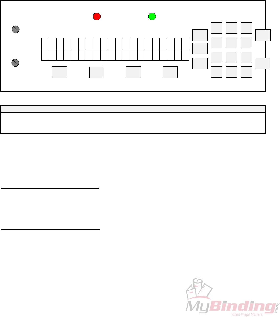
4.0 GW 6000 OPERATION
PHOTOCELL
SAFETY
SET
FWD CLR
BWD
H1 H2
IMPRESSION
CONTROL
START
STOP
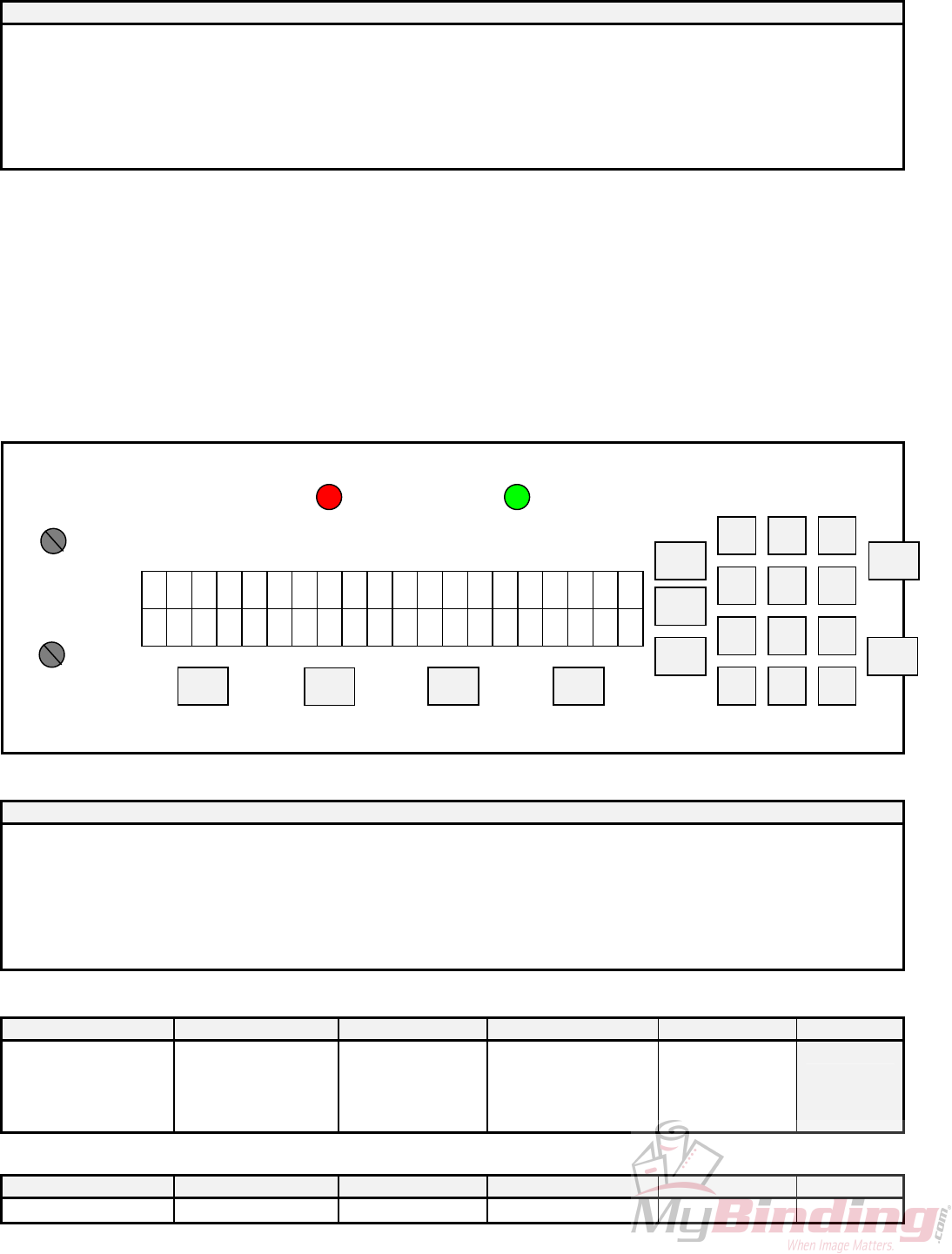
The operating keyboard is comprised of six LED segments, various buttons and a Impression
Control which consist of one potentiometer knobs that control the crash strength of the numbering
heads, and can be adjusted to best suit the requirements of the job. For example, you may require
stronger crash numbering for carbonless sets than for single sheet bond paper. This adjustment can be
done while the machine is stopped or running.
The four buttons under the LED display will perform whatever function is shown directly on
them.
SET/FWD – Is used to set up a numbering job and incrementing the motor in a forward direction.
CLR/BWD- Is used to clear programs and increment
the motor backwards.
PHOTOCELL
SAFETY
SET
FWD CLR
BWD
H1 H2
IMPRESSION
CONTROL
START
STOP
H1- Is used to control head number one which is the
head closest to the operator.
H2- Is used to control head number two which is the
head furthest away from the operator.
START – Is used to start the machine.
STOP- Is used to stop the machine.
Once you have plugged the machine in, turn the on/off switch to the 'on' position. The LED
display will be blank for a second the two lights for the safety lid and photocell will light up. The
system will do a check on each LED line segment and then look like the above.
The Sprint 6000 does systematic error checks, if it detects an error it will display a numeric
value.
4.1 Running a Job
The machine is capable of storing a maximum of 1 job with 10 hits for recall and future use.
Ensure that there is paper in the feed tray first. Pressing the 'START' button will automatically begin
the program that was previously programmed in the memory.
4.2 Stopping a Job
There are two methods of stopping the machine.
1. Once the program is running, pressing the 'STOP' button will cause the machine to finish the
stock it is currently working on, move the next stock into the starting position and then stop the motor.
- 11 -
2. If you want to stop the machine while stock is still left in it, simply hold on to the stock in the
feed tray. After about one second, the machine will automatically stop (since it is no longer seeing
any new sheets). This is how it also stops when all of the stock in the feed tray is gone.
4.3 Clearing A Job
To completely clear a program from the memory insert a paper in the feed tray. Press the
SET/FWD button. The paper will then feed through and stop at 75. Press the CLR button and hold it
down, next press the H2 button and this will clear the memory.
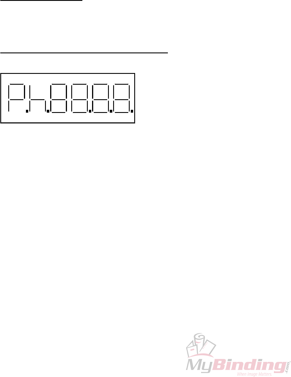
4.4 Changing and Programming a Job
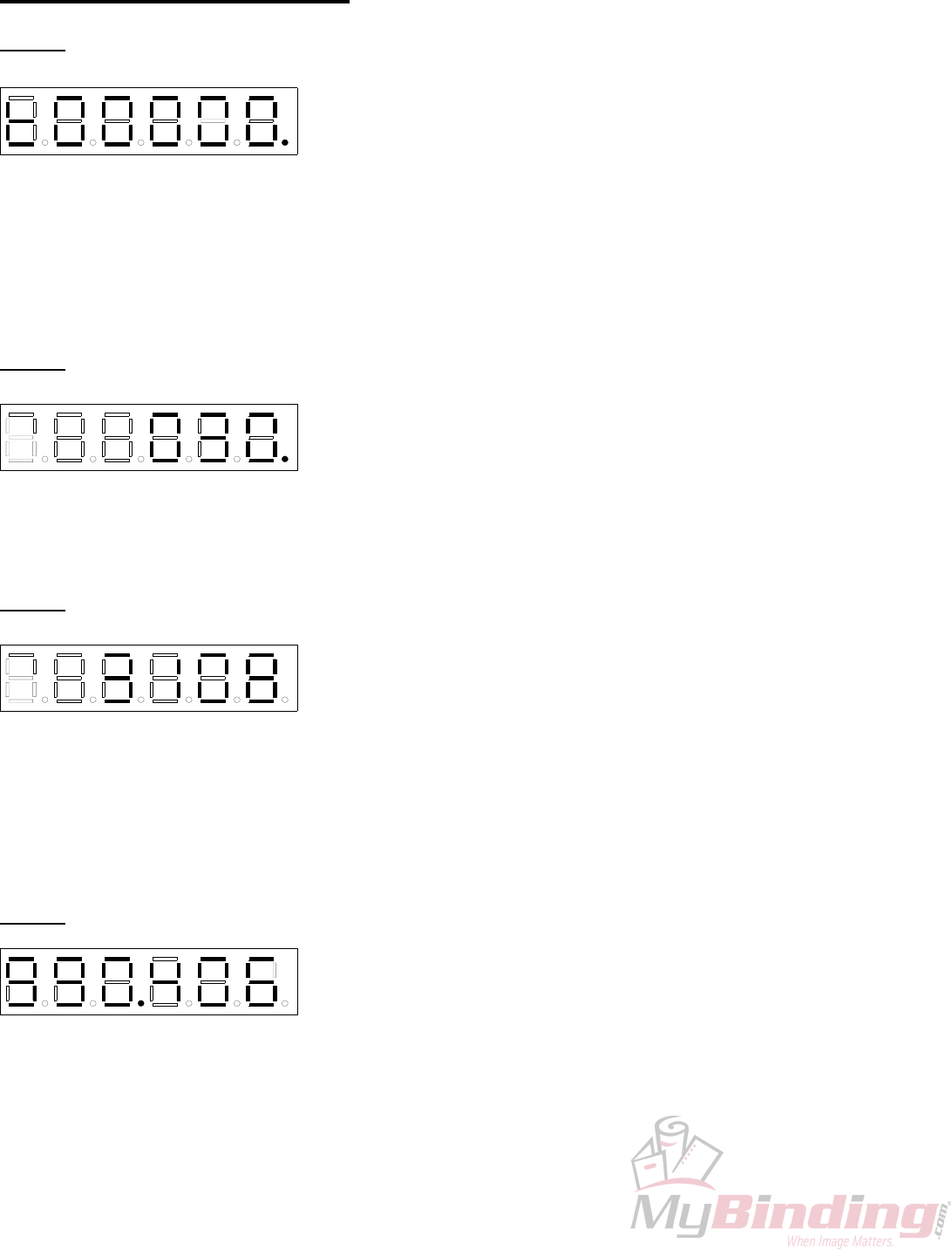
Whenever you wish to change or program a job,
insert a piece of paper into the feed tray and press
the SET/FWD button. The paper will go through
the machine and stop in front of the photocell.
The DIG 5 will have P indicating you are in the
program mode, DP 5 will light up indicating the
motor is on in the forward position, DIG 1-0 will
have 75 and DP 0 will light up indicating that a
hit exists in the program. To clear the memory
completely press the CLR/BWD button, while holding it down press the H2 button, you will notice DP
0 will go off, this indicates that the memory and all hits have been cancelled.
DIG 5 DIG 4 DIG 3 DIG 2 DIG 1 DIG 0
DP 5 DP 4 DP 3 DP 2 DP 1 DP 0
As a guide, refer to the orientation of the LED digit segments (DIG 5-0) and the Decimal point
functions (DP 5-0) in the picture.
DIG 5 – Displays “P” for Program Set-up.
DIG 4 – Displays “h” only if a hit has been programmed at the current position.
DIG 3 - DIG 0 – Current paper position in steps from the paper leading edge. In run mode they act as
paper count.
DP 5 – Indicates the motor direction On = Forward
DP 4 – If it is on it indicates all 10 hit positions are used.
DP 3 – No function.
DP 2 – Solenoid 1 – On indicates Head 1 will be fired at the current position.
DP 1 – Solenoid 2 – On indicates Head 2 will be fired at the current position.
DP 0 – Indicates a hit exists in the program.
Changing the position of a hit can be done by scrolling (SET/FWD or CLR/BWD) to where the
previous hit existed. Once there the head will fire and you will have an “h” displayed in DIG 4, the
numbers indicate the stepper count position. You will also have either DP 1 and/or DP 0 lit depending
on which numbering head was activated. Pressing Either H1 or H2 will toggle the lights off or on.
When DP 1 or DP 0 is off, it indicates there is no longer a hit programmed at that position. Now by
scrolling with the SET/FWD or CLR/BWD buttons you can reposition the number hit.
Once all is set, press START and “SAVE” will display in DIG 5-2 and the current sheet will
eject. The machine will go into the idle mode. This will show DIG 4-0 as 0’s. Any numbers on the
display will be a paper count; pressing the CLR/BWD button will clear this back to zero.
To run the job, insert paper into the feed tray and press start.
- 12 -
4.5 SPEED CONTROL
The GW 6000 is equipped with three speeds. Slow speed is the default when you first run the program.
While the program is running press ‘H1 and/or H2’ you will notice on the far-left side of the display
vertical lines. Three of these lines indicate high speed, two for medium and one for low speed.
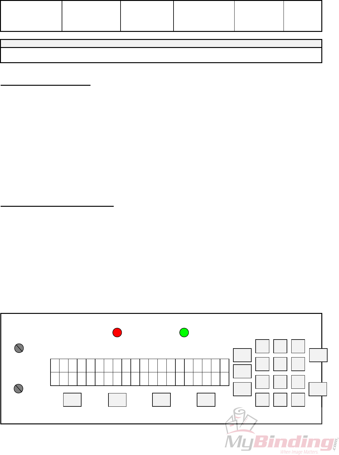
4.6 GW 6000 SOFTWARE SET UP and DIAGNOSTICS
DIG 0DIG 5
DP 5 DP 4 DP 3 DP 2 DP 1
DIG 4 DIG 3 DIG 2 DIG 1
DP 0
IMPRESSION
PERF SHIELD (RED)
STOP
H2 H1 SET/FWD CLR/BWD
START
PHOTOCELL (GRN)
The GW 6000, performs a limited set of self-diagnostics on power up. A full set of diagnostic utilities is
accessed by a manufacturing test mode. The system indicates paper error conditions along with hardware
faults by displaying a message on the LED display during operation.
All settings are simple enough for the customer to be coached through via telephone. We however recommend
that they only be done on site, by the dealer.
4.7 OVERVIEW
Access to all settable parameters is available through the keyboard while in the main operating menu. This is
the menu display when the machine is first turned on. If you are not at this point, press ‘STOP’ as often as
required to return to the main operating menu.
When at this point press ‘STOP’ and while holding it down press ‘H1’ and ‘H2’ at the same time. The display
will read “tESt01”. The test program is one of 10 available items. Each of the others is accessible by scrolling
with the ‘SET/FWD’ or ‘CLR/BWD’ buttons and then ‘START’ will allow you to enter that specific item
number.
- 13 -
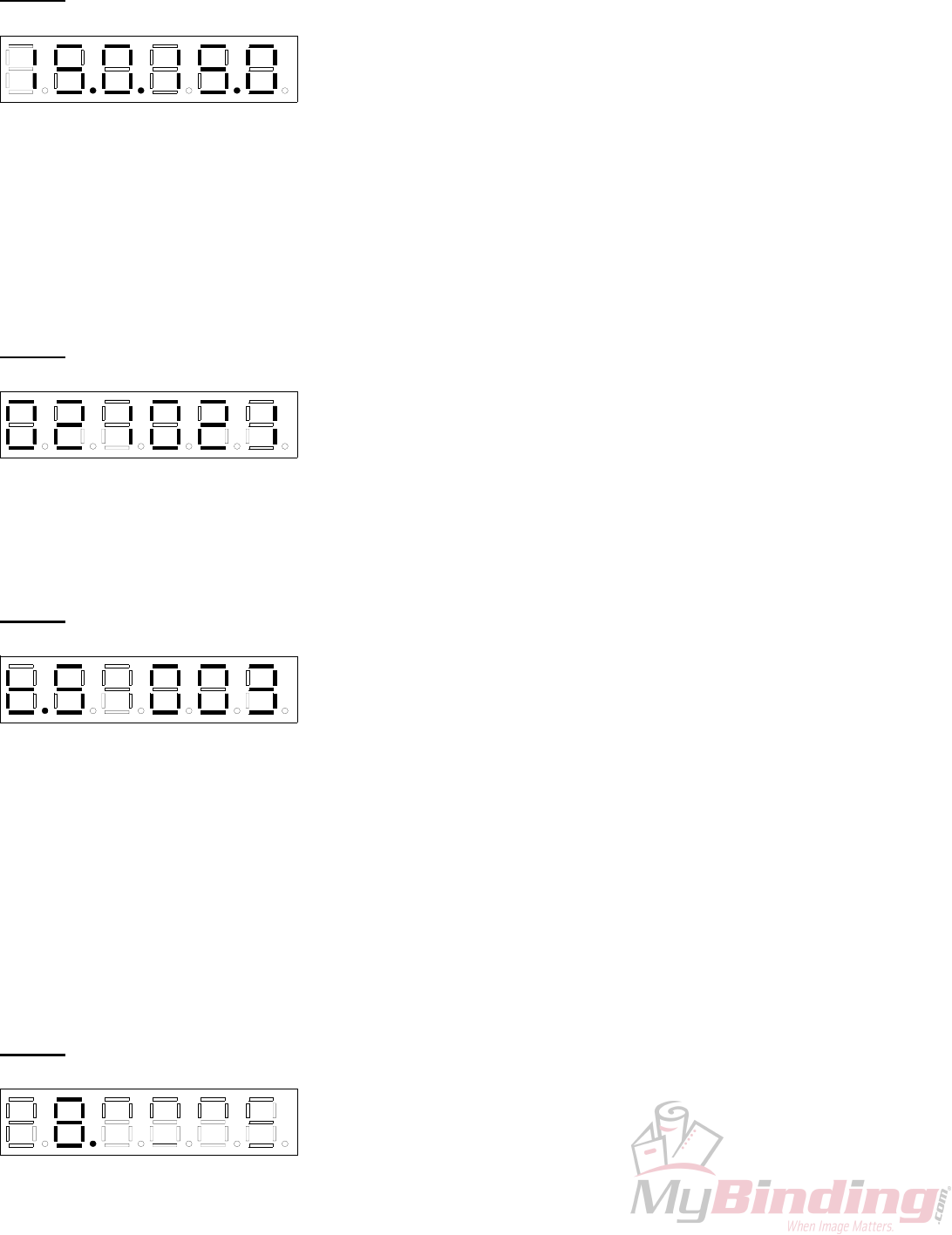
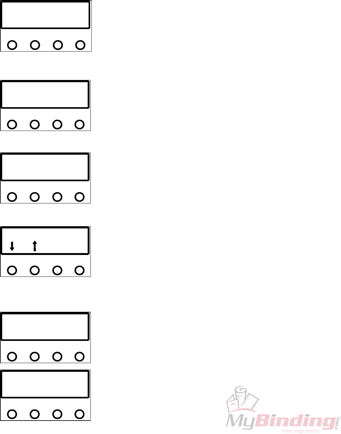
4.8 INDIVIDUAL ITEMS
tESt01 – TEST RUN
DIG 0DIG 5
DP 5 DP 4 DP 3 DP 2 DP 1
D G 4 DIG 3 DIG 2 DIG 1
DP 0
When selected, this program will run the default factory program. The
motor will run, stop, start and the heads will fire simulating a standard
run. This is useful after replacing a component on the machine and
testing its correct installation. We run each machine for three full days in
our plant using this program to burn in the circuits and weed out any other assembly or miscellaneous
problems. DP4 allows for a single hit program by pressing ‘SET/FWD’ it will come on or go off. This light is
usually off allowing for a ten hit program. DP0 is always on indicating hits existing in the default program.
Pressing the ‘CLR/BWD’ will clear the simulated paper count.
To exit this item press ‘STOP’.
tESt02 – DISPLAY PHOTOCELL ADC
DIG 0DIG 5
DP 5 DP 4 DP 3 DP 2 DP 1
D G 4 DIG 3 DIG 2 DIG 1
DP 0
This is a machine value for the photocell. The value should be
approximately 60. Making adjustment on the gray pot located on the
PSTEP board can change this value. This is the bigger board located on
the non-operator side of the machine. The pot is located at the top
midsection of the board beside the two, four pin connectors.
To exit this item press ‘STOP’.
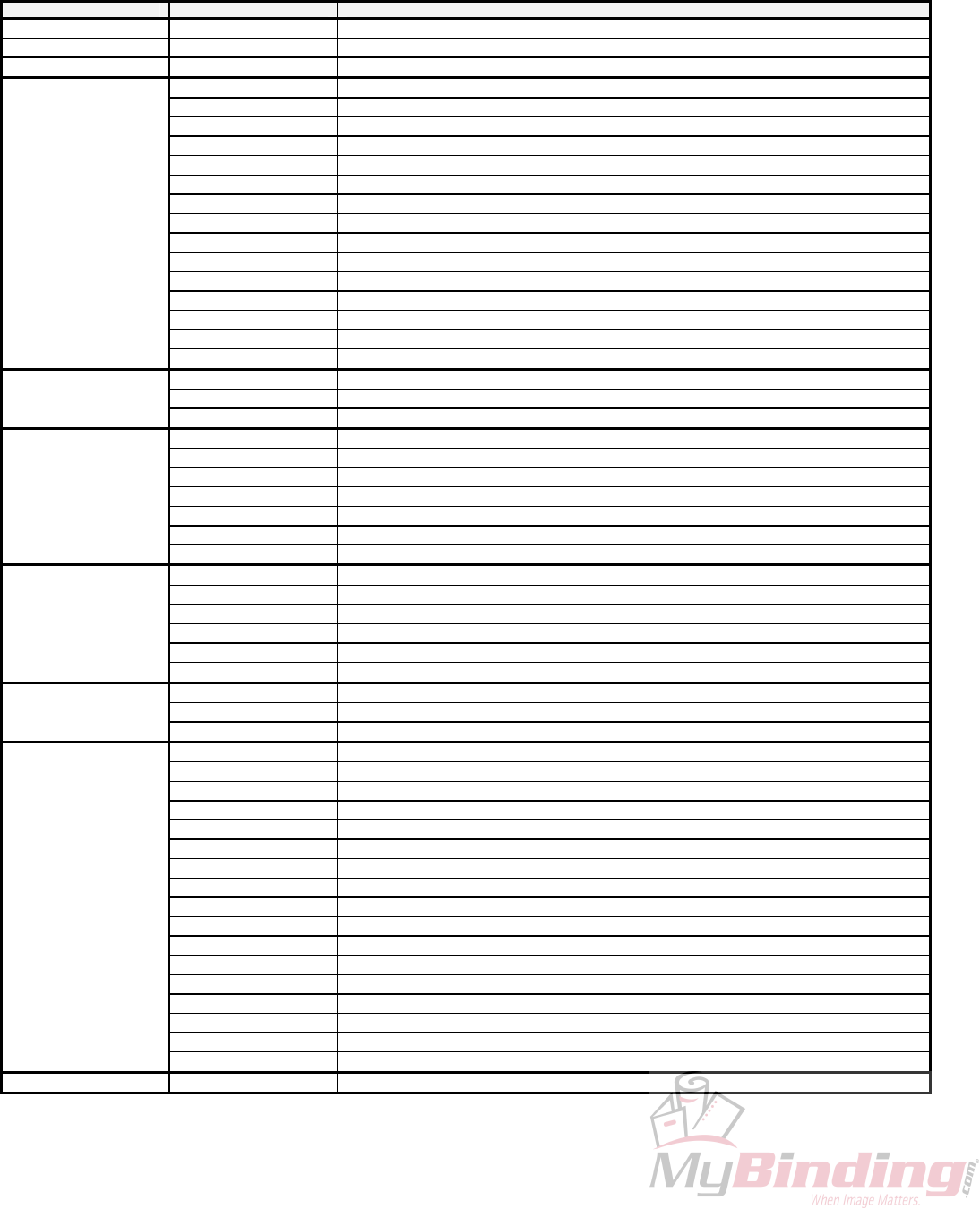
tESt03 – DISPLAY VOLTAGES
DIG 0DIG 5
DP 5 DP 4 DP 3 DP 2 DP 1
D G 4 DIG 3 DIG 2 DIG 1
DP 0
This displays the motor off-line, DIG2-0 will display the line voltage (it
will be lower than the actual line voltage), DIG5-3 will read the actual
motor voltage, when off-line the voltage will read around 0. When ‘H2’
is pressed DP3 will light up indicating that the machine is now on-line at
this point the numbers to the left of the dot will be the actual motor voltage, and the number to the right is the
actual input line voltage reading. The motor voltage typically will be around 150V if the voltage is higher than
160V then there is a problem. In 220-volt systems the line voltage will be approximately half of the actual line
input voltage.
To exit this item press ‘STOP’.
tESt04
DIG 0DIG 5
DP 5 DP 4 DP 3 DP 2 DP 1
D G 4 DIG 3 DIG 2 DIG 1
DP 0
– DISPLAY SOFTWARE VERSION
This mode will indicate the software version dates of the ICPU software
and the MSTP software. Default on entry is the ICPU Software Version,
indicated by DP3. Pressing ‘H2’ will display the MSTP version in
which the DP3 will disappear and ‘H1’ will get you back to the ICPU
version.
To exit this item press ‘STOP’.
- 14 -
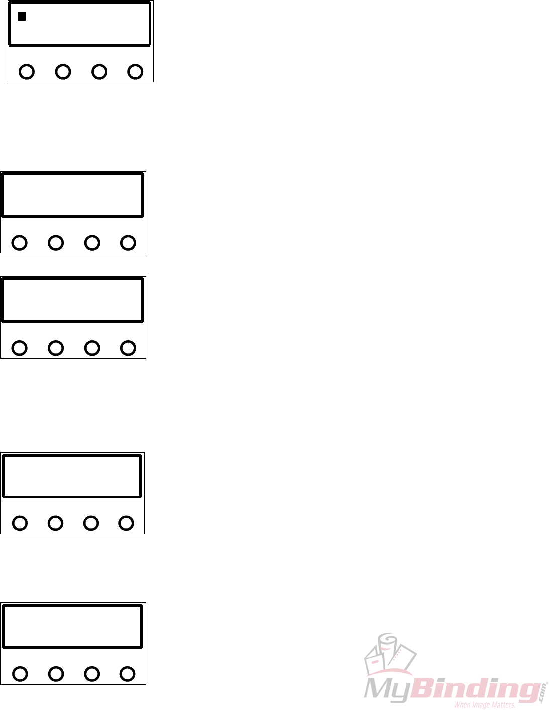
tESt05 – SET SOLENOID MINIMUM PULSE WIDTH
DIG 0DIG 5
DP 5 DP 4 DP 3 DP 2 DP 1
D G 4 DIG 3 DIG 2 DIG 1
DP 0
This will display and modify Channel 1 and/or Channel 2 minimum
pulse width parameters. The Minimum Pulse Width value is 10 msec
and the maximum is 20 msec. Default is set at 15 msec. It is factory set
at 13.5. DP4 is a decimal point; DP3 indicates that Channel 1 has been
selected DP1 is a decimal point, DP0 will indicate when Channel 2 has been selected. DIG5-3 are the values
for Channel 1 and DIG2-0 are for Channel 2. The ‘SET/FWD’ increments and the ‘CLR/BWD’ decrements,
these buttons will vary the value by 0.1 msec increments when pushed, holding down will fast increment the
numbers.
Pressing ‘Stop’ will abort the pulse width changes and exit to the Manufacturer Test Mode display screen.
Pressing ‘START’ will store the new pulse width changes in the EEPROM, the display will flash ‘SAVE’ and
the machine will exit to the Manufacturer Test Mode display screen.
tESt06 – TEST SOLENOIDS
DIG 0DIG 5
DP 5 DP 4 DP 3 DP 2 DP 1
D G 4 DIG 3 DIG 2 DIG 1
DP 0
This will test solenoid channel pulsing with automatic detection of head
presence on each channel. It displays the ADC reading continuously.
The Impression Pot. varies the solenoid channel pulse width. Pressing
‘CLR/BWD’ will toggle the Solenoid Test On-Line this is indicated by
DP4 being lit. Pressing and holding ‘SET/FWD’ and either ‘H1’ or ‘H2’ the machine will start continuously
simulating pulsing.
To exit this item press ‘STOP’.
tESt07 – TEST STEPPER
DIG 0DIG 5
DP 5 DP 4 DP 3 DP 2 DP 1
D G 4 DIG 3 DIG 2 DIG 1
DP 0
This will test the stepper motor; motor direction, motor on-line/off-line,
motor current limit, and running the motor either continuously or
cycling the motor on for 10 seconds and off for 1 second. DP5 indicates
the direction of the motor, when lit it is in the forward direction,
pressing ‘CLR/BWD’ will turn it off indicating the motor direction will rotate backward. The button
‘SET/FWD’ will put the light back on in the forward direction. Pressing either ‘SET/FWD’ or ‘CLR/BWD’
will run the motor in that direction for one step, continuously holding it will run the motor continuously at
setup speed. DP4 indicates whether the motor is on/off-line, pressing ‘H1’ will toggle this light on or off. DP3
indicates whether the motor is running in high/low current, when the light is on it is in high current. To toggle
from high to low press ‘H2’. To run the motor must be online, pressing ‘START’ will let you run the motor
continuously. If you press and hold down the ‘H1’ button then press ‘H2’ the motor will run for 10 seconds
then turn off for one second and repeat the whole cycle again.
If the motor is running ‘STOP’ will stop it.
To exit this item press ‘STOP’.
tESt08 – TEST LEDS
DIG 0DIG 5
DP 5 DP 4 DP 3 DP 2 DP 1
D G 4 DIG 3 DIG 2 DIG 1
DP 0
This function will test all the following indicators; individual digit
segments, entire digits, decimal points, photocell/perf shield LEDs.
Pressing ‘SET/FWD’ will cycle all the segments in DP5 and DIG5.
Each press of the ‘CLR/BWD’ will cycle through DIG4-0, DP4-0 one
digit, with each digit displaying “8”. ‘H1’ triggers the photocell LED, ‘H2’ the perf shield LED.
- 15 -

To exit this item press ‘STOP’.
tESt09 – TEST POT/KEYS This program allows individual testing of all keys and impression pot.
Each key will turn on a decimal point while pressed. ‘SET/FWD’ turns
on DP5 while pressed. ‘CLR/BWD’ turns on
DIG 0DIG 5
DP 5 DP 5 DP 5 DP 5 DP 5
D G 4 DIG 3 DIG 2 DIG 1
DP 5
DIG 0DIG 5
DP 5 DP 5 DP 5 DP 5 DP 5
D G 4 DIG 3 DIG 2 DIG 1
DP 5
DP4. ‘H1’ turns on DP3. ‘H2’ turns on DP2. ‘STOP’ turns on DP1 and ‘START’ turns on DP0.
To exit out of this mode press and hold down the ‘H2’ and then the ‘STOP’.
tESt010 – TEST/FORMAT EEPROM
This tests and formats the EEPROM sections that are used by loading
the programmable parameter defaults into the EEPROM and RAM. It
will also write an empty solenoid program into the memory. Pressing
the ‘CLR/BWD’ will commence erasing the EEPROM, DP4 will turn
on while the Test/Format is in progress. Notice, once the formatting is initiated it cannot be aborted.
To exit this item press ‘STOP’.
- 16 -
4.9 GW 6000 Error Codes
Group Condition Error
Paper Handing Errors 01 PAPER JAM
05 MSTP PAPER ERROR REPORTED IS UNDEFINED
02-04, 06-09 Reserved
Solenoid Errors 10 CH1 OPEN
11 CH1 SHORT
12 CH1 HOT
13 CH2 OPEN
14 CH2 SHORT
15 CH2 HOT
16 CH1 2 HEADS
17 CH2 2 HEADS
18 NO SOLENOID BOARD ATTACHED
19 LOW VOLTAGE SOLENOID BOARD ATTACHED
20 SOLENOID TIMEOUT
21 SOLENOID BOARD TYPE INCONSISTENT (BETWEEN MSTP AND ICPU)
22 SOLENOID ADC LIMITS ARE INCONSISTENT (BETWEEN MSTP AND ICPU)
23-28 Reserved
29 MSTP REPORTED UNKNOWN SOLENOID ERROR
Motor Errors 30 MOTOR RUN TIMEOUT
31 MOTOR TURN ON/OFF TIMEOUT
32-39 Reserved
EEPROM Errors 40 UNABLE TO READ FROM EEPROM
41 UNABLE TO WRITE TO EEPROM
42 CRC INVALID FOR EEPROM PROGRAMMABLE PARAMETERS
43 CHECKSUM INVALID FOR EEPROM SOLENOID PROGRAM
44 TESTING FAILED DURING TEST/RE-FORMAT EEPROM
45 EEPROM VERSION FORMAT ID# DOES NOT MATCH SOFTWARE
44-49 Reserved
Memory Errors 50 RAM SELF-TEST READ/WRITE FAILURE
51 CHECKSUM INVALID FOR RAM SOLENOID PROGRAM
52 CRC INVALID FOR RAM PROGRAMMABLE PARAMETERS
53 SETUP MODE SOLENOID PROGRAM HIT INDEX OUT OF RANGE
54 SOLENOID PROGRAM NUMBER IS CORRUPT
55-59 Reserved
Hardware Errors 60 AC LINE VOLTAGE OUT OF OPERATION RANGE
61 MOTOR VOLTAGE OUT OF OPERATION RANGE
62-69 Reserved
SCI Errors 70 ICPU SCI RECEIVE TIMEOUT ERROR
71 ICPU SCI RECEIVE OVERFLOW ERROR
72 ICPU SCI TRANSMIT TIMEOUT ERROR
73 ICPU SCI INVALID ACK RECEIVED
74 ICPU SCI CORRUPTED MESSAGE RECEIVED
75 ICPU SCI TRANSMIT ABORTED
76 ICPU SCI WATING PERIOD FOR MSTP MESSAGE EXPIRED
77 ICPU SCI INVALID MESSAGE TYPE RECEIVED
80 MSTP SCI RECEIVE TIMEOUT ERROR
81 MSTP SCI RECEIVE OVERFLOW ERROR
82 MSTP SCI TRANSMIT TIMEOUT ERROR
83 MSTP SCI INVALID ACK RECEIVED
84 MSTP SCI INVALID COMMAND RECEIVED
85 MSTP RECEIVE OVERRUN ERROR
86 MSTP RECEIVE FRAMING ERROR
77-79, 87-88 Reserved
89 MSTP SCI ERROR REPORTED IS UNDEFINED
Miscellaneous 90 MSTP ERROR REPORTED IS UNDEFINED
- 17 -
5.0 GW 8/12000 OPERATION
G R A P H I C W H
C A N A D A
I Z A R D
F1
>>>
F2
<<<
STOP
START
REP
BAT
ACC
ESC 0
97 8
64
2 31
5
SETUP
SETUP
IMPRESSION 2
IMPRESSION 1
FLASHES IF RAM ERROR FLASHES IF LCD ERROR
PERF SHIELD (RED) PHOTOCELL (GRN)
N
O FUNCTION
The operating keyboard is comprised of a two line LCD display, various buttons and two Impression
Controls which consist of two potentiometer knobs that control the crash strength of the numbering head, and
can be adjusted to best suit the requirements of the job. For example, you may require stronger crash
numbering for carbonless sets than for single sheet bond paper. This adjustment can be done while the
machine is stopped or running.
The four buttons under the LCD display will perform whatever function is shown directly above them
on the bottom line of the LCD display. They may not always be active (this is the case for the other buttons as
well). Three specific function buttons (SET UP, BAT, REP) are situated beside the display. A numeric
keypad, an ‘ESC’ (escape), ‘ACC’ (accept), ‘START’ and ‘STOP’ button rounds out the rest of the
keyboard. The 'ESC' button can be used at almost any time (except during actual running) in order to return
to the previously viewed menu. The functions of the rest of the buttons will be discussed later in this section.
Once you have plugged the machine in, turn the on/off switch to the 'on' position. The microprocessor
does an internal system check and the above will flash on the screen.
5.1 Running a Job
The Idle Mode is displayed below. From this menu, you can change the motor speed, modify your
paper count and select your program.
In this menu you can also enter the Batch size.
s s s s s s P G M
↓
↑
x x x c c
c c
a
c
a
c
a 1-
F1
>>>
F2
<<<
STOP
START
REP
BAT
ACC
ESC 0
97 8
64
2 31
5
SETUP
SETUP
IMPRESSION 1
IMPRESSION 2
ON = PERF SHIELD OPEN ON = NO PAPER
PERF SHIELD (RED) PHOTOCELL (GRN)
- 18 -
DISPLAY FUNCTIONS:
DISPLAY
ssssss = motor speed bar graph
PGMxxx = solenoid program in RAM
cccccc = paper count
↓ = decrement motor speed
↑ = increment motor speed
-1 = decrement paper count
aaa = CLR -> clear paper count normally; aaa = BAT -> Enter Mode - Set Batch Size when batch mode is enabled
The <<</>>> will adjust the motor speed, F1 will decrement the paper count, F2 will clear the paper count but
if it is already at 0 it will send you to the Batch mode. SETUP will select a program and START will begin
the job. You will now be in the Run Mode.
When the machine is first turned on, it defaults to Program 01 (PGM001), which is shown on the
menu. Pressing the 'START' button will automatically begin Program 01. The main operating menu will
change as the machine is running.
The Run Mode menu looks like this:
s s s s s s P G M
↓
↑
x x x c c
c c
a
c
a
c
a TLAH
F1
>>>
F2
<<<
STOP
START
REP
BAT
ACC
ESC 0
97 8
64
2 31
5
SETUP
SETUP
SOL CH2 ADJUST
PULSE WIDTH
IMPRESSION 2
SOL CH1 ADJUST
PULSE WIDTH
IMPRESSION 1
ON = PERF SHIELD OPEN
(
WILL EXIT TO Mode - Idle
)
ON = NO PAPER
PERF SHIELD (RED) PHOTOCELL (GRN)
DISPLAY FUNCTIONS:
DISPLAY
ssssss = motor speed bar graph
PGMxxx = solenoid program in RAM
cccccc = paper count
↓ = decrement motor speed
↑ = increment motor speed
HALT = motor emergency stop, exit to Mode - Idle
aaa = CLR -> clear paper count normally; aaa = BAT -> Display current batch size when batch mode is enabled
KEYPAD FUNCTIONS:
<<< >>> F1 F2 STOP START
DECREMENT MOTOR SPEED INCREMENT MOTOR SPEED MOTOR EMERGENCY
STOP
Exit to Mode - Idle
IF BATCH SIZE IS ZERO
CLEAR PAPER COUNT
ELSE:
DISPLAY BATCH SIZE
Complete numbering
Eject current sheet
Stop motor
Exit to Mode - Idle
ACC ESC SETUP BAT REP
MOTOR EMERGENCY STOP MOTOR EMERGENCY STOP MOTOR EMERGENCY IF BATCH SIZE IS ZERO MOTOR EMERGENCY
- 19 -
Exit to Mode - Idle Exit to Mode - Idle STOP
Exit to Mode - Idle MOTOR EMERGENCY STOP
Exit to Mode - Idle
ELSE:
DISPLAY BATCH SIZE
STOP
Exit to Mode - Idle
DIG 0-9
MOTOR EMERGENCY STOP
Exit to Mode - Idle
5.2 Stopping a Job
Here are methods of stopping the machine.
1. Once the program is running, there are several built in safety emergency stops. Pressing the STOP
button, any of the digits 0-9, F1, STOP, ACC, ESC, REP, and if the Batch size is 0, BAT will cause the
machine to finish the stock it is currently working on, move the next stock into the starting position and then
stop the motor. This automatically sends you into Idle Mode.
2. If you want to stop the machine while stock is still left in it, simply hold on to the stock in the feed
tray. After about one second, the machine will automatically stop (since it is no longer seeing any new
sheets). This is how it also stops when all of the stock in the feed tray is gone.
5.3 Changing Programs
The GW 8/12000 allows you several choices in programming:
PROGRAM 00 = Perf/score, automatically turns the numbering heads off.
PROGRAM 01 – 99 = Allows for a maximum of 10 hits per head.
PROGRAM 100 = Allows for a maximum of 100 hits per head.
Whenever you wish to change programs, the LCD display must be in Idle Mode press the 'SET UP'
button. The following screen will appear:
DISPLAY:
S E L E C T P R O G R A M
E
x x
D
T
x
I NUR
F1
>>>
F2
<<<
STOP
START
REP
BAT
ACC
ESC 0
97 8
64
2 31
5
SETUP
SETUP
N
O FUNCTION
IMPRESSION 2
N
O FUNCTION
IMPRESSION 1
ON = PERF SHIELD OPEN ON = NO PAPER
PERF SHIELD (RED) PHOTOCELL (GRN)
- 20 -
Once you select the program number desired, you may either 'RUN' the existing program or 'EDIT' it
by pressing the corresponding function key (F1 to RUN & F2 to EDIT).
If RUN is selected, the machine will exit to Idle Mode where you press START. The ESC key will
also return to Idle Mode in case you wish to change the counter before beginning a job.
5.4 Programming a Job
If you wish to program a job, EDIT an existing program, press F2. After selecting EDIT, if the
program already exists, the machine will ask whether you would like to erase it, start new ('NEW') or modify
it ('MOD').
P R O G R A M : X X
M O D N E
X E X I S
B
S
A
T
K
C TIXE W
F1
>>>
F2
<<<
REP
BAT
ACC
ESC 0
97 8
64
2 31
5
SETUP
SETUP
N
O FUNCTION
IMPRESSION 2
IMPRESSION 1
ON = PERF SHIELD OPEN ON = NO PAPER
PERF SHIELD (RED) PHOTOCELL (GRN)
STOP
START
This selection is done with the corresponding function key (<<< and >>> respectively).
When modifying a program, previously programmed hits can be removed from the program while
additional hits may be added.
Once you make your selection, the machine will instruct you to 'INSERT PAPER/ PRESS START'.
The LCD display will then show the following:
+
P G M : x x x P O S : c c c
c
C
c
4
2 31C >> > < < <
F1
>>>
F2
<<<
STOP
START
REP
BAT
ACC
ESC 0
97 8
64
2 31
5
SETUP
SETUP
N
O FUNCTION
IMPRESSION 2
N
O FUNCTION
IMPRESSION 1
ON = PERF SHIELD OPEN ON = NO PAPER
PERF SHIELD (RED) PHOTOCELL (GRN)
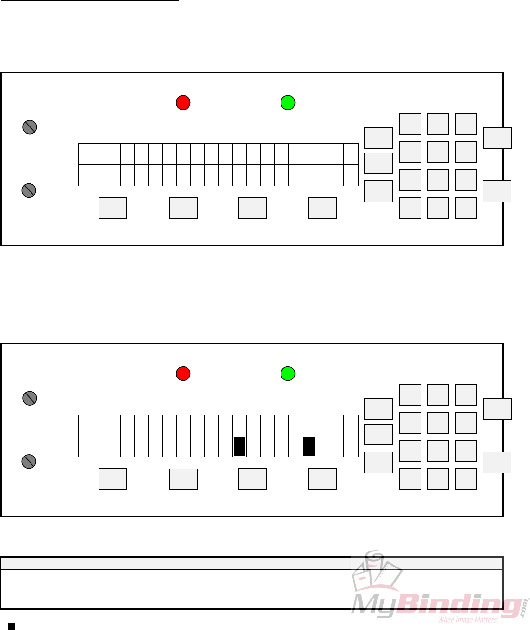
DISPLAY FUNCTIONS:
DISPLAY
xxx = solenoid program number
ccccc = current paper position in motor steps from paper lead edge
<<< = motor moves in forward direction
- 21 -

22
>>> = motor moves in backward direction
= full block character displayed when hit programmed
C1 = solenoid channel 1 head 1
3 = solenoid channel 1 head 2 = SOL3
C2 = solenoid channel 2 head 1
4 = solenoid channel 2 head 2 = SOL4
The sheet you inserted is automatically moved to position '75'. Position '0' is the lead edge of the
sheet passing the photocell. Position '75' is the first location that an entire number will print on the paper.
(Note: Each step represents approximately 1/50th of an inch).
The first two function keys step the paper either forward or backward (Note: you cannot back the sheet
back further than position '75'). The other two function keys fire either head #1 or head #2. Once a head fire
button has been pressed, the numbering head will fire and the LCD display will light up with one solid bar
around the corresponding head fired (eg.C1).
In a four head system, heads 1&3 work together and heads 2&4 respectively. To activate heads 1&3 at
any position press “F1” head 1 will fire and C1 will appear on the display press “3” on the keypad and head
3 will fire and C13 will appear. To activate head 2&4 you must press the number “2 and 4” on the keypad
and C24 will appear on your display.
Configured, we can have in any one program, with a four head machine, a combination of, at any one
time; heads 1&2&3&4, 1&3, 2&4, 1, 2. Heads 3&4 cannot activate on their own.
If the number is not in the position desired, simply press the function button again to toggle off the hit,
otherwise continue moving up or down the sheet (the hit is automatically saved). This procedure can be
repeated until the number is in the correct location. The page can be stopped a maximum of 15 times where
you may program head #1 or head #2 or both heads to fire.
Once all numbers desired have been programmed, simply press the 'ACC' button and the sheet will be
discharged from the machine. The next sheet will be forwarded to step '75' (if there is another sheet already in
the feed tray) or you will be instructed to 'INSERT PAPER/PRESS START'. The LCD display will return
to Idle Mode and you are set to run the job. Simply press the 'START' button to begin.
23
5.5 The Batch Function
Pressing the 'BAT' key before running a program will enter the batch menu.
FUNCTION:
1. Allows user to set or clear the batch size, max. batch size = 999999
2. Sets a new batch size by pressing <ACC>. The paper count and batch quantity are reset to 0.
DISPLAY:
B A T C H S I Z E x
x x
C
x
R
x
L TES
F1
>>>
F2
<<<
STOP
START
REP
BAT
ACC
ESC 0
97 8
64
2 31
5
SETUP
SETUP
N
O FUNCTION
IMPRESSION 2
N
O FUNCTION
IMPRESSION 1
ON = PERF SHIELD OPEN ON = NO PAPER
PERF SHIELD (RED) PHOTOCELL (GRN)
DISPLAY FUNCTIONS:
DISPLAY
xxxxx = batch size
SET = sets the batch size
CLR = sets the batch size to zero
At this point you may select the size of the batch desired by entering the desired batch size through the
keypad. Press the 'ACC' key when the quantity desired has been chosen. Press the 'F2' key (CLR) if you wish
to clear a quantity entered to disengage the batch function. Once again, the 'ESC' key will return you back to
the main operating menu without activating the batch function. Pressing “F1” will reset the paper count and
batch quantity.
24
When running a job with the batch function, the machine will stop after the last sheet has been
processed, leaving the sheet partially in the exit rollers, allowing you to insert a slipsheet. The LCD display
will then show the number of batches completed.
FUNCTION:
1. Displays the number of batches that have been completed of Batch Size
DISPLAY:
B A T C H Q T Y : x
x x
C
x
R
x
L TIXE
F1
>>>
F2
<<<
STOP
START
REP
BAT
ACC
ESC 0
97 8
64
2 31
5
SETUP
SETUP
N
O FUNCTION
IMPRESSION 2
IMPRESSION 1
ON = PERF SHIELD OPEN ON = NO PAPER
PERF SHIELD (RED) PHOTOCELL (GRN)
DISPLAY FUNCTIONS:
DISPLAY
xxxxx = batch quantity
EXIT = exit to Mode - Idle
CLR = clear batch quantity
This screen will show you how many batches you have completed. Multiply the 'BATCH QTY' by the
'BATCH SIZE', and you have the total quantity of your run. When the machine stops after each batch has
been completed, you may insert a slip sheet in the exit tray and simply press the 'START' button to continue
with the next set.
5.6 The Repeat Function
The repeat function key (REP) is a future feature for the GW 8/12000. Currently the repeat selector
on the numbering head is used to obtain a repeat ability.
5.7 Motor Speed Control
The motor speed can be changed while the machine is running or idle. This function is performed by
using the first two function keys under the LCD display screen (marked << and >>) when you are in the main
operating menu.
The bottom line of the LCD display shows a down arrow to slow down the motor and an up arrow to
speed it up. Maximum throughput speed is 8 000 (GW 8000) and 12 000 (GW 12 000) sheets per hour (11 x
82" or A4), with one number per page.

25
5.8 GW 8/12000 SOFTWARE SET-UP & DIAGNOSTICS
2
01 TEST IDLE
H1
<< >>
<<< >>>
H2 SAFETY
4 5
F2F1
REP
ESC 0
7
BAT
8
PHOTOCELL
1
SET
UP
6
ACC
STOP
9
START
3
On both models, the software offers a number of technician settable features and diagnostics. Using these, the
equipment can be customised to the customer's requirements and/or tuned to local electrical conditions.
The most critical of these is the minimum solenoid pulse width. Each customer location will offer a
different incoming voltage. This voltage variation can result in an incorrect range of impression control being
available to the user. While most other values will remain at factory defaults, this value must be changed for
each new machine location.
All settings are simple enough for the customer to be coached through via telephone. Upon installation or in
the event of a circuit exchange, the Set-Up routine must be followed to ensure proper set-up.
5.9 OVERVIEW
Access to all settable parameters is available through the keyboard while in the main operating menu. This is
the menu displayed when the machine is first turned on. If you are not at this point, press "ESC" as often as
required to return to the main operating menu.
When at this point to get into the Manufacturer Test Menu, press "1,2,9'". The display will read "01 TEST
IDLE". The test program is one of the 10 available options. Each of the others is accessible by pressing the
appropriate number at any time or pressing the "<<" or ">>“ keys to scroll forward or backward through the
options and then "ACC" to enter that option. Leave any item by pressing "ESC or STOP".
5.10 INDIVIDUAL ITEMS
Each of the available options provides a different function and will either assist in machine set up or in
diagnosing a malfunction. Each is detailed and explained below.
01. TEST IDLE
When selected, "1 TEST IDLE" will run the current machine program over and over without the need to load
paper. The motor will run, stop, start and the heads will fire simulating a standard run. This is useful after
replacing a component on the machine and testing its correct installation. We run each machine for a
minimum 48 hours in our plant using this program to burn in the circuits and to weed out any other assembly
or miscellaneous problems.
02. DISPLAY PCELL ADC
26
PHOTOCELL ADC: 030
<< F2>> F1
EXIT
The photocells in the GW 8000 & 12000 are of a reflective type. The actual
emitter/collector are in one stock electronic component. It is mounted on the
leading edge of the main platen operator side underneath a grooved cutout.
Above the photocell is a shiny reflector that is in a fixed position. Adjustment
on the photocell is now done directly on the main PSTEP board. The value
should be between 55-65.
03. DISPLAY VOLTAGES
This mode will display the line voltage and the actual motor voltage. When
the motor is not in operation the voltage will read approximately 0, this is
represented by the OFF beside the number. Pressing ‘F2’ will bring the motor
online (ONL). While online the typical voltage will be about 150. If the
reading is above 160 there is a problem.
MOTOR VOLTAGE : 003OFF
LINE VOLTAGE: 109
<< F2>> F1
04. DISPLAY SW DATES
ICPU : REV V990511
PSTP : REV V990528
<< F2>> F1
The software versions on the ICPU and MSTP Board are displayed.
05. SET LANGUAGE
There is a choice of five languages to choose from; ENGLISH, SPANISH,
GERMAN, PORTUGESE and FRENCH. Use the ‘<< or >>’ buttons to scroll
through the different languages, when you select the one press ‘F2 or ACC’.
<<
ENGLISH
F2
EXIT SET
>> F1
06. TEST SOLENOIDS
In this mode you can test or set the minimum solenoid pulse width. The test
mode allows you to check the functionality of the low voltage solenoid board.
Once ‘>>’ is pressed you are in the test mode.
TEST SOLENOID : LOW
TEST EXIT SET
<< F2>> F1
PW1 stands for Pulse Width for Head 1 and PW2 for H2. The values beside
them are the Pule Widths in nano seconds. They vary when the Impression
Control Dials are turned. With the dials completely counter cockwise it will
display the minimum solenoid pulse width. With the heads plugged in ‘F1’
will fire H1 each time it is pressed. ‘F2’ will fire H2 also each time it is
pressed. To obtain a continuous pulse press the ‘<<’ key. To set the
PW1 : 15000
<< >>
PW2 : 15000
F2F1
minimum solenoid pulse widths press ‘STOP’ and then ‘F2’.
mPW1 : 15.0
<< >>
mPW2 : 15.0
F2F1
The block beside the number indicates which head is currently being fired
by selecting ‘F1 or F2’. The keys ‘<< and >>’ increase or decrease the pulse
width. With the air pressure through the regulator set between 40-50 psi
adjust the pulse width value up or down to provide a well inked number
which does not emboss a light paper weight (20#/75 gsm bond). The next
head can be adjusted in this same manner. Default setting for this is 15.0 on
the pneumatic units. The factory setting is set at 12.5. When finished press
‘ACC’ to save the value to the EEPROM and you will go back to the Manufacturer Test Menu. If you do not
want to save the changes press ‘ESC’ and you will go to MFR Test Menu, or ‘Stop’ will put you in the
‘Test/Set Menu.
7. TEST STEPPER This Mode allows the user to run a Stepper Motor Test and to set the
Maximum Motor Speed. The Maximum Motor Speed is factory set and
should not be changed. To TEST the Motor press the ‘>>’ key. The factory
setting for the GW 8000 is 79 and the GW 12000 at 90.
TEST STEPPER MAIN
TEST EXIT SET
<< >> F2F1
The number beside the PER is the Motor Period in microseconds by turning
the Impression Control Dial for H2 the number will either increase or
decrease, the higher the number the slower the motor will go. Beside the MOT
V is the actual motor voltage, when OFF the voltage will be around 0.
PER : 00444 MOT V : 003
FWD BWD OFF LO
W
<< >> F2F1
To run the motor it must be Online as indicated when ‘F1’ is the toggle and
ONL appears, the machines voltage will now read around 150 V. ‘F2’ will
toggle the motor HIGH or Low Current Limit. Each pressing of the ‘<< or>>’ will move the motor one step,
continuously holding it down will run the motor only at SET-UP SPEED. If ‘START’ is pressed the machine
will run continuously only in the FORWARD direction and the Motor Period will change with the H2
Impression Dial. If the ‘SETUP’ button is pressed the motor will cycle on and off every 10 seconds.
PT1 : aaa XXXXXXXXXX
PT2 : bbb XXXXXXXXXXX
>>
<< F1 F2
8. TEST POT AND KEYS
This test program will allow you to check the functionality of all the keys on
the display and also the Impression Control Dials.The display will show two
lines. PT1 represents the ADC value of Head #1, and when the Impression
Control Dial for the head is turned the values beside PT1 will accordingly
increase or decrease. The same is done for the Impression Control Dial for
Head #2. The X’s to the left will disappear any time a key on the display pad
is pressed.
LOAD DEFAULTS
PARM PGMS EXIT
<< >> F1 F2
9. LOAD DEFAULTS
This function allows the loading of the entire factory set programs and
parameters into the EEPROM. All the existing EEPROM data will then be
overwritten. PGMS will clear all this existing solenoid programs from the
memory and load the factory set solenoid programs from 01-100. When
PARM or PGMS is pressed a secondary confirmation screen will be
displayed.
27

28
CONFIRM LOAD DEFAULT
aaaa YES BACK
<< >> F1 F2
Once PARM or PGMS is selected the confirmation screen will display which
was selected on the bottom left and then accordingly press F1 for Yes or F2 to
go back.
IIIIIIIIIIIIIIIIII FORMAT EEPROM
EXIT CLR
<< >> F1 F2
10. TEST/FORMAT EEPROM
This function will erase all programs and set the factory defaults. It will
totally erase the EEPROM and reprogram all the programmable parameter
defaults along with the solenoid program defaults. CLR will load an empty
program into all the program locations of the EEPROM it will then display a
secondary “CONFIRM FORMAT” screen before erasing the existing data,
when formatting an update completion bar will indicate the progress. Once
format is complete, the screen will display “FORMAT COMPLETE”. Note, that once formatting has
commenced, the user cannot abort formatting operation.
5.11 GW 8/12000 ERROR MESSAGES
Group Error Message Description
Paper Handing Errors PAPER JAM A PAPER JAM CONDITION EXISTS
INSERT PAPER A PAPER OUT CONDITION EXISTS
PAPER TOO LONG A PAPER LONG CONDITINO EXISTS
PAPER TOO SHORT A PAPER SHORT CONDITION EXISTS
Solenoid Errors SOL ERROR 10 SOLENOID CHANNEL 1 OPEN
SOL ERROR 11 SOLENOID CHANNEL 1 SHORT
SOL ERROR 12 SOLENOID CHANNEL 1 HOT
SOL ERROR 13 SOLENOID CHANNEL 2 OPEN
SOL ERROR 14 SOLENOID CHANNEL 2 SHORT
SOL ERROR 15 SOLENOID CHANNEL 2 HOT
SOL ERROR 16 RESERVED
SOL ERROR 17 RESERVED
SOL ERROR 18 NO SOLENOID BOARD ATTACHED
SOL ERROR 19 RESERVED
SOL ERROR 20 MSTP DID NOT REPORT SOLENOID(S) FIRED
SOL ERROR 21 ICPU AND MSTP SOLENOID BOARD TYPE DO NOT MATCH
SOL ERROR 22 ICPU AND MSTP SOLENOID ADC LIMITS DO NOT MATCH
SOL ERROR 23 SOLENOID CHANNEL 1 REPORTED ONLY 1 HEAD INSTEAD OF 2
SOL ERROR 24 SOLENOID CHANNEL 2 REPORTED ONLY 1 HEAD INSTEAD OF 2
Motor Errors MOT ERROR 30 MOTOR RUN TIMEOUT
MOT ERROR 31 MOTOR TURN ON/OFF TIMEOUT
EEPROM Errors EEP ERROR 40 UNABLE TO READ FROM EEPROM
EEP ERROR 41 UNABLE TO WRITE TO EEPROM
EEP ERROR 42 CRC INVALID FOR EEPROM PROGRAMMABLE PARAMETERS
EEP ERROR 43 CHECKSUM INVALID FOR EEPROM SOLENOID PROGRAM
EEP ERROR 44 TESTING FAILED DURING TEST/RE-FORMAT EEPROM
EEP ERROR 45 EEPROM VERSION FORMAT ID# DOES NOT MATCH SOFTWARE
Memory Errors RAM ERROR 50 RAM SELF-TEST READ/WRITE FAILURE
RAM ERROR 51 CHECKSUM INVALID FOR RAM SOLENOID PROGRAM
RAM ERROR 52 CRC INVALID FOR RAM PROGRAMMABLE PARAMETERS
RAM ERROR 53 SETUP MODE SOLENOID PROGRAM HIT INDEX OUT OF RANGE
RAM ERROR 54 SOLENOID PROGRAM NUMBER CORRUPTED
Hardware Errors LINE VOLTAGE ERROR AC LINE VOLTAGE OUT OF OPERATION RANGE
MOTOR VOLTAGE ERROR MOTOR VOLTAGE OUT OF OPERATION RANGE
SCI Errors SCI ERROR 70 ICPU SCI RECEIVE TIMEOUT ERROR
SCI ERROR 71 ICPU SCI RECEIVE OVERFLOW ERROR
SCI ERROR 72 ICPU SCI TRANSMIT TIMEOUT ERROR
SCI ERROR 73 ICPU SCI INVALID ACK RECEIVED
SCI ERROR 74 ICPU SCI CORRUPTED MESSAGE RECEIVED
SCI ERROR 75 ICPU SCI TRANSMIT ABORTED
SCI ERROR 76 ICPU SCI WAITING PERIOD FOR MSTP MESSAGE EXPIRED
SCI ERROR 77 ICPU SCI INVALID MESSAGE TYPE RECEIVED
SCI ERROR 80 MSTP SCI RECEIVE TIMEOUT ERROR
SCI ERROR 81 MSTP SCI RECEIVE OVERFLOW ERROR
SCI ERROR 82 MSTP SCI TRANSMIT TIMEOUT ERROR
SCI ERROR 83 MSTP SCI INVALID ACK RECEIVED
SCI ERROR 84 MSTP SCI INVALID COMMAND RECEIVED
SCI ERROR 85 MSTP RECEIVE OVERRUN ERROR
SCI ERROR 86 MSTP RECEIVE FRAMING ERROR
Miscellaneous UNKOWN ERROR MSTP ERROR REPORTED IS UNDEFINED
29
6.0 CIRCUIT BOARDS LAYOUT AND DIAGNOSTICS
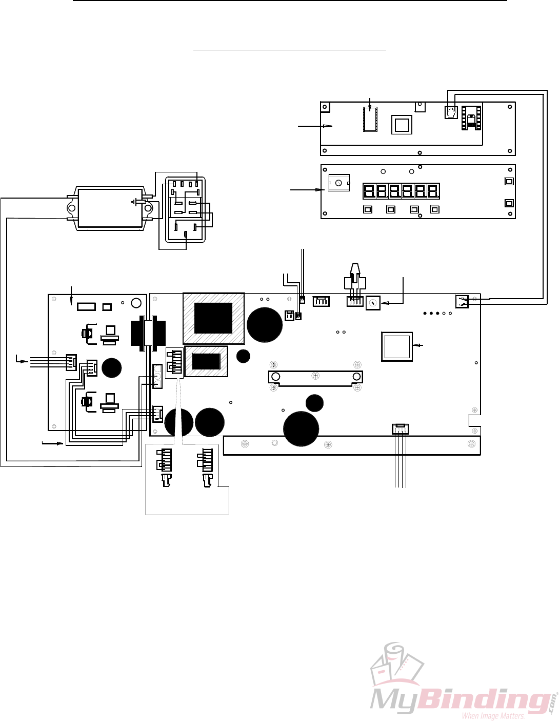
6.1 GW 3/6000 CIRCUIT
12 V COOLING
FAN
90-032-GW
6K LED/ICPU DISPLAY BOARD
BACK
92-029-GW-X
3 K
90-029-GW
6K LED/ICPU DISPLAY BOARD
FRONT
92-029-GW-X
3 K
90-029-GW
FILTER TO MSTP BOARD CABLE
90-064-GW
HV SOLENOID TO MSTP
BOARD POWER CABLE
90-068-GW
BLACK
RED
RED
BLACK
S/N: 035
SOLENOID CONNECTION
BOARD TO FEMALE TERMINAL
90-069-GW
BLUE
YELLOW
YELLOW
BLUE
BLACK
120 V
MSTP BOARD
CONNECTOR
90-060-GW
B01
PURPLE
220 V
MSTP BOARD
CONNECTOR
90-061-GW
LD1
LD2
LD3
HIGH VOLTAGE SOLENOID BOARD
90-028-GW
90-028-GW-X
LINE FILTER
90-063-GW
BROWN
BLUE
BROWN
BROWN
GREEN
BLUE
BLUE
MODULAR SWITCH
W/FUSEHOLDER
90-062-GW
BLUE
6K MSTP EPROM
92-026-GW
3K MSTP EPROM
90-026-GW
3K MSTP BOARD
90-025-GW-X
6K MSTP BOARD
92-025-GW-X
ORANGE
RED
BLACK
VOLET
STEPPER MOTOR
W/HARNESS
90-005-GW
LD4
LD7
7
S/N: 069
LD7
LD7
PSTPSW
V990415
@1999
GRAPHIC
WHZARD
A03
LD8
LD10
LD9
LD11
PHOTOCELL
ASSEMBLY
90-067-GW
GREEN
SAFETY SWITCH
W/HARNESS
90-016-GW
BLACK
RED
RED
BLACK
BLACK
RED
PHOTOCELL VOLTAGE
POTENTIOMETER
WHITE
6K ICPU EPROM
92-027-GW
S/N: 048
GRAPIC W IZARD CANA
S6KSW
V 99031
@199
A00
TELEPHONE CABLE
90-030-GW
040
REV: A
S/N:
A00
30
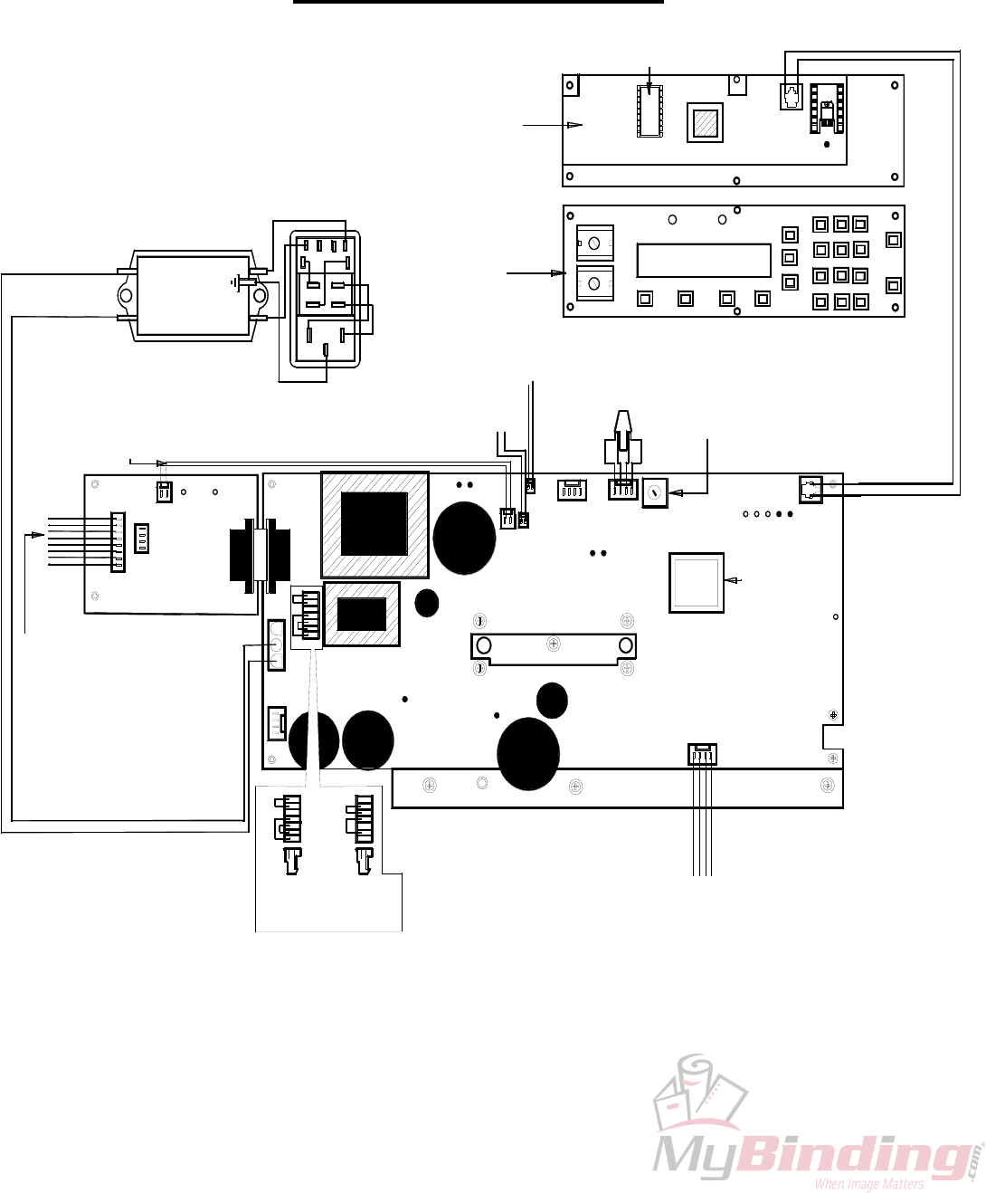
6.2 GW 8/12000 CIRCUIT
12 V COOLING
FAN
90-032-GW
LD3
LED/ICPU DISPLAY BOARD
FRONT
94-029-GW
94-029-GW-X
LED/ICPU DISPLAY BOARD
BACK
94-029-GW
94-029-GW-X
LD2
LOW VOLTAGE SOLENOID BOARD
94-028-GW
94-028-GW-X
FILTER TO MSTP BOARD CABLE
90-064-GW
LOW VOLTAGE SOLENOID
CONNECTION BOARD TO
FEMALE TERMINAL
96-071-GW
LD10
220 V
MSTP BOARD
CONNECTOR
90-061-GW
PURPLE
BLACK
120 V
MSTP BOARD
CONNECTOR
90-060-GW
LD8
LD1
LINE FILTER
90-063-GW
BROWN
BLUE
HV SOLENOID TO MSTP
BOARD POWER CABLE
90-083-GW
BROWN
MODULAR SWITCH
W/FUSEHOLDER
90-062-GW
GREEN
BROWN
BLUE
BLUE
BLUE
STEPPER MOTOR
W/HARNESS
90-005-GW
MSTP BOARD
92-025-GW
92-025-GW-X
MSTP EPROM
92-026-GW
LD9
LD4
ORANGE
RED
BLACK
VOLET
LD5 LD6
S/N: 069
PSTPSW
V990415
@1999
GRAPHC
WHIZARD
A03
LD8
LD7
LD11
LD10
PHOTOCELL VOLTAGE
POTENTIOMETER
S/N: 048
PHOTOCELL
ASSEMBLY
90-067-GW
8K SAFETY SWITCH W/HARNESS
90-016-GW
12K SAFETY SWITCH W/HARNESS
96-016-GW
RED
BLACK
BLACK
RED
BLACK
RED
GREEN
WHITE
ICPU EPROM
94-027-GW
GRAPIC W IZARD CANADA
S6KSW
V 99531
@1999
TELEPHONE CABLE
90-030-GW
REV A
B00
A00
040
S/N
LD1
31

GW 3/6/8/12000 CIIRCUIT DIAGNOSTICS
Purpose:
• This document provides
• a brief overview of the functions of the LED indicators on all GW boards
• how to correct, if possible, error messages on the displays
LED Indicators:
• PSTP Board
• All LEDs have a brief (one word) indicator on the silkscreen beside the LED
• This describes the main function of the LED
• LD1: +320V Supply Indicator
• This LED indicates whether the +320V supply is alive
• If this LED is not on then the possible causes are (in order of probability):
• Machine not turned on
• Fuse Blown
• AC power connector not plugged into J2 on PSTP board or cable is broken
• Jumper not in J5 or incorrect jumper in J5 (black for 110VAC, purple for 220VAC)
• Bridge doubler not functioning – replace PSTP board
• LD2: Secondary +5V Supply Indicator
• This LED indicates whether the secondary +5V supply is alive
• If this LED is not on then the possible causes are:
• Machine not turned on
• AC power connector not plugged into J2 on PSTP board (or cable broken)
• Jumper not in J5 or incorrect jumper in J5 (black for 110VAC, purple for 220VAC)
• X2, VR2 or VR1 not functioning or short on S+5V line – replace PSTP board
• LD3: Secondary +12V Supply Indicator
• This LED indicates whether the secondary +12V supply is alive
• If this LED is not on then the possible causes are:
• Machine not turned on
• AC power connector not plugged into J2 on PSTP board (or cable broken)
• Jumper not in J5 or incorrect jumper in J5 (black for 110VAC, puple for 220VAC)
• X2, VR2 not functioning or short on S+12V line– replace PSTP board
• LD4: Motor Voltage Supply Indicator
• This LED indicates whether the motor voltage supply is alive
• This LED should only be on when the motor is brought online
• If this LED is not on then the possible causes are:
• Motor not online
• +320V supply not functioning – verify that LD1 is on
• motor switching supply not functioning – replace PSTP board
32

• LD5: Primary +12V Supply Indicator
• This LED indicates whether the primary +12V supply is alive
• If this LED is not on then the possible causes are:
• Machine not turned on
• AC power connector not plugged into J2 on PSTP board (or cable broken)
• Jumper not in J5 or incorrect jumper in J5 (black for 110VAC, purple for 220VAC)
• X1 or VR4 not functioning or short on P+12V line– replace PSTP board
• LD6: Primary +5V Supply Indicator
• This LED indicates whether the primary +5V supply is alive
• If this LED is not on then the possible causes are:
• Machine not turned on
• AC power connector not plugged into J2 on PSTP board (or cable broken)
• Jumper not in J5 or incorrect jumper in J5 (black for 110VAC, purple for 220VAC)
• X1, VR3 or VR4 not functioning or short on P+5V line– replace PSTP board
• LD7: Perf Status Indicator
• This LED indicates the status of the Perf
• If the Perf is closed, LD7 will be on
• If the Perf is open, LD7 will be off
• If this LED does not change state when opening/closing the Perf shield then the
possible causes are:
• Perf cable not plugged into J11 on PSTP board or Perf cable broken
• Perf switch broken
• Perf circuitry not functioning – replace PSTP board
• LD8: Start Photocell Status Indicator
• This LED indicates the status of the Start Photocell – paper reflects to detector
• If there is no paper under the photocell, LD8 will be off.
• If there is paper under the photocell, LD8 will be on.
• If this LED does not change state when breaking the Start Photocell then the possible
causes are:
• Start Photocell not plugged into J12 on PSTP board or Photocell cable broken
• Photocell not aligned properly or photocell broken
• Start photocell circuitry not functioning – replace PSTP board
• LD9: Paper Photocell Status Indicator
• This LED indicates the status of the Paper Photocell – paper breaks refection to
detector
• If there is no paper under the photocell, LD9 will be on
• If there is paper under the photocell, LD9 will be off
• If this LED does not change state when breaking the Paper Photocell then the
possible causes are:
• Paper Photocell not plugged into J13 on PSTP board or Photocell cable broken
• Photocell not aligned properly or photocell broken
• Paper photocell circuitry not functioning – replace PSTP board
33

• LD10: PSTP Transmit Indicator
• This LED is an indicator whenever the PSTP board communicates to the
ICPU/Display boards
• When the PSTP transmits, LD10 should flash for a short period of time
• When the PSTP is not transmitting, LD10 should be off
• If this LED does not flash ~ 4s after power up or if it is always on, then the possible
causes are:
• SCI phone cable not plugged into J15 on PSTP board and J1 on ICPU board
• SCI phone cable made incorrectly or broken
• Incorrect SW version for PSTP (3K SW not compatible with ICPU board)
• PSTP transmit circuitry not working (error message should be displayed) – replace
PSTP board
• LD11: PSTP Receive Indicator
• This LED is an indicator whenever the ICPU/Display boards communicate to the
PSTP board
• When the ICPU transmits, LD10 should flash for a short period of time
• When the ICPU is not transmitting, LD10 should be off
• If this LED does not flash ~ 4s after power up or if it is always on, then the possible
causes are:
• SCI phone cable not plugged into J15 on PSTP board and J1 on ICPU board
• SCI phone cable made incorrectly or broken
• Incorrect SW version for PSTP (3K SW not compatible with ICPU board)
• PSTP receive circuitry not working (error message should be displayed) – replace
PSTP board
• NOTE: for the 3K machine LD10 should always be on and LD11 should flash dimly when
keys are pressed on the KPAD
• High Voltage Solenoid Board
• The probable causes for HVS faults assume that there are no problems with the PSTP
board
• All of the problems listed above for the PSTP board are not present
• LD1: Primary +12V Supply Indicator
• This LED indicates whether the primary +12V logic supply on the HVS board is alive
• If this LED is not on then the possible causes are:
• Short on the P+12V line or R48 opened – replace HVS board
• Low Voltage Solenoid Board
• The probable causes for LVS faults assume that there are no problems with the PSTP
board
• All of the problems listed above for the PSTP board are not present
• LD8: Primary +12V Supply Indicator
34

• This LED indicates whether the primary +12V logic supply on the LVS board is alive
• If this LED is not on then the possible causes are:
• Short on the P+12V line – replace LVS board
• LD10: Secondary +12V Supply Indicator
• This LED indicates whether the Secondary +12V logic supply on the LVS board is
alive
• If this LED is not on then the possible causes are:
• LVS cable not plugged into J15 on LVS board and J8 on PSTP board
• LVS cable broken or not made correctly
• Short on the S+12V line – replace LVS board
• ICPU/Display Boards
• The probable causes for ICPU faults assume that there are no problems with the PSTP
board
• All of the problems listed above for the PSTP board are not present
• LD1: Secondary +5V Supply Indicator
• This LED indicates whether the secondary +5V supply on the ICPU is alive
• If this LED is not on then the possible causes are:
• SCI phone cable not plugged into J15 on PSTP board and J1 on ICPU board
• SCI phone cable made incorrectly or broken
• VR1 not functioning or short on S+5V line – replace ICPU board
• 3K Keypad
• The probable causes for LVS faults assume that there are no problems with the PSTP
board
• All of the problems listed above for the PSTP board are not present
• If Perf and Photocell LEDs do not change state when open/close perf and break Pcell
then the possible causes are:
• SCI phone cable not plugged into J15 on PSTP board and J1 on KPAD board
• SCI phone cable made incorrectly or broken
• KPAD board not functioning – replace KPAD board
Error Messages:
• Errors At Power up
• Solenoid Errors
• If this error occurs the machine should be powered down and then power back up again to verify
that the error occurs at least two consecutive times.
• If a solenoid error occurs at power up then the most likely cause is:
• Incorrect solenoid board attached to PSTP board
• Incorrect ICPU/Display SW
35

• This error cannot be cleared by a keypress – the fault must be fixed in order to clear the error
• EEPROM Errors
• If an EEP error occurs at power up then the most likely cause is:
• Switching PSTP boards without reformatting the ICPU EEPROM
• Faulty EEPROM on ICPU
• If encounter EEP errors at power up:
• Press STOP or ESC until all EEP errors are cleared
• Format EEP
• Power the machine down
• Power up the machine again
• If still encounter EEP errors replace ICPU board
• SCI Errors
• If SCI errors occur at power up they cannot be cleared by a keypress - the fault must be fixed
in order to clear the error
• To clear fault/isolate the problem refer to section above for PSTP transmit and receive LEDs
• Error could also be caused by SW mismatches – verify that PSTP SW is compatible with
ICPU SW
• RAM Errors (6K, 8K and 12K only)
• If this error occurs at power up, this error is display by flashing the Photocell LED on the display
boards
• If RAM errors occur at power up they cannot be cleared by a keypress - the fault must be fixed
in order to clear the error
• The probable cause of the problem is a faulty RAM chip – replace ICPU board
• Errors Encountered when Running Programs
• Paper Errors
• Generally paper errors can be cleared by hitting STOP or ESC
• The error message displayed should be looked up in error messages table to identify the cause
of the problem in order to fix it
• Solenoid Errors
• Generally solenoid errors can be cleared by hitting STOP or ESC
• The error message displayed should be looked up in error messages table to identify the cause
of the problem in order to fix it
• SCI Errors
• Generally SCI errors can be cleared by hitting STOP or ESC
36

• If the error message keeps recurring then there is probably a fault with either the hardware or
software
• Power down the machine and then power up again
• If get SCI errors then to clear fault/isolate the problem refer to section above for PSTP
transmit and receive LEDs
• Motor Errors
• Generally motor errors can be cleared by hitting STOP or ESC
• If the error message keeps recurring then there is probably a fault with the hardware – replace
PSTP board
3K Error Messages:
• Error messages for the 3K are displayed on the perf and photocell LEDs
• Observe when the Perf LED (red) flashes
• Count how many times the Photocell LED (green) flashes until the Perf LED flashes again
• The number of times the Photocell LED flashes corresponds to the error (see error message
table for 3K)
• Errors At Power up
• EEPROM Errors
• If an EEP error occurs at power up then the most likely cause is:
• Not formatting PSTP EEPROM
• Faulty EEPROM on PSTP
• If encounter EEP errors at power up:
• Press STOP – PSTP should automatically reformat EEPROM
• Power the machine down
• Power up the machine again
• If still encounter EEP errors replace PSTP board
• Errors During Program Running
• Paper Errors
• Generally paper errors can be cleared by hitting STOP
• The error message displayed should be looked up in error messages table to identify the cause
of the problem in order to fix it
• Solenoid Errors
• Generally solenoid errors can be cleared by hitting STOP
• The error message displayed should be looked up in error messages table to identify the cause
of the problem in order to fix it
37
7.0 GW PARTS LIST
38
PART NO. JR
. 3K 6K 8K 12K FM
100 FM
150 DESCRIPTION
10-001-GW X X X X X Red, Preinked Pad w/holder
10-002-GW X X X X X Black, Preinked Pad w/holder
10-003-GW X X X X X Uninked pad w/holder
10-004-GW X X X X X Felt Insert
10-005-GW X X X X X Red Ink, 4 oz. bottle
10-006-GW X X X X X Black Ink, 4 oz. bottle
10-007-GW X X X X X Changestick
10-008-GW X X X X X X 3/32" Hexdriver
10-009-GW X X X X X X X 5/32" Hexdriver
10-010-GW X X X X X X Ring Pliers
10-011-GW X X X X X X X ¾" Snap Ring
10-012-GW X X X X X Reverse Numbering Head (6 digits, 2 drop)
10-013-GW X X X X X Forward Numbering Head (6 digits, 5 drop)
10-014-GW X X X X X Condensed Reverse Numbering Head (8 digits, 4 drop)
10-015-GW X X X X X Date Stamp Head (month/day/year)
10-016-GW X X X X X 5/8" Wave Washer
10-017-GW X X X X X X Feed Tray
10-018-GW X X X X X X Feed Tray Side Guides
10-019-GW X X X X X X Feed Tray Slot Cover
10-020-GW X X X X X X Locking Wingnuts
10-021-GW X X X X X X Feed Platen Retarding Strip
10-022-GW X X X X X X Feed Shaft Adjust Screw
10-023-GW X X X X X X Locking Thumbnut
10-024-GW X X X X X X Roller Tire (feed/main/exit)
10-025-GW X X X X X X Roller Hub
10-026-GW X X X X X X Roller Shaft
10-027-GW X X X X X X 3/8 " Set Screw Collar
10-028-GW X X X X X X Shaft Bushing
10-029-GW X X X X X X Feed Shaft Bushing w/Spring
10-030-GW X X X X X X Shaft Bushing w/Spring
10-031-GW X X X X Solid Bottom Roller
10-032-GW X X X X Main Platen Crash Pad
10-033-GW X X X X Main Platen
10-034-GW X X X X Main Platen Grommets
10-035-GW X X X X Main Platen Mount Brackets
10-040-GW X X X X X Hand Knob
10-041-GW X X X X X 5/16" Disc Spring
10-042-GW X X X X X 5/16" Flat Washer
10-043-GW X X X Solenoid w/plunger
10-044-GW X X X Solenoid plunger
10-045-GW X X Pneumatic Cylinder
10-046-GW X X Pneumatic Valve Controller
10-047-GW X X Regulator, Manifold, Gauge Assembly w/hose
10-048-GW X X 3/8 ” Hose (4’ length)
10-049-GW X X 3/8 “ Hose Quick Connect
10-050-GW X X ¼ ” Hose (4 ½ ‘ length)
10-051-GW X X ¼ “ Hose Quick Connect
10-053-GW X X X X X Drive Unit Cover
PART NO. JR
. 3K 6K 8K 12K FM
100 FM
150 DESCRIPTION
10-054-GW X X X X X Print Head Mount
10-055-GW X X X X Exit Tray
10-056-GW X X X X Magnetic Tray Side Guides
10-057-GW X X X X X Magnets
10-058-GW X X X X X X Handwheel
10-059-GW X X X X X X X 120V Modular Line Cord
10-065A-GW X 3A,250V Fast Blow Fuse
10-065-GW X X 3A,250V Slow Blow Fuse
10-066-GW X X X X 5A, 250V Slow Blow Fuse
10-068-GW X X X X X Impression Control Dial Knob
10-071-GW X X X X X ½ “ Cord Strain Relief
10-084-GW X X X X X X Accessory Holder w/12 TPI perf blade
10-085-GW X X X X X X Accessory Holder Adjust Screw
10-086-GW X X X X X X Blade Mount Hub w/bearing
10-088-GW X X X X X X Accessory Holder w/idler wheel
10-089-GW X X X X X X Idler Wheel Tire
10-090-GW X X X X X X Boss Wheel
10-091-GW X X X X X X 2 TPI Perf. Blade
10-092-GW X X X X X X 4 TPI Perf. Blade
10-093-GW X X X X X X 6 TPI Perf. Blade
10-094-GW X X X X X X 8 TPI Perf. Blade
10-095-GW X X X X X X 12 TPI Perf. Blade
10-096-GW X X X X X X Microperf (42 TPI) Blade
10-097-GW X X X X X X Microperf (72 TPI) Blade
10-098-GW X X X X X X Slit Blade
10-099-GW X X X X X X Score Blade
10-100-GW X X X X X X Narrow Score Blade
10-101-GW X X X X X X Double Score (1/4 " separation) w/Holder & Boss
15-005-GW X X X X X Red Quick Drying Ink, 2 oz. Bottle
15-006-GW X X X X X Black Quick Drying Ink, 2 oz. Bottle
15-036-GW X X X X ¾ “ Keyed Drive Unit Mount Shaft
15-037-GW X X X X Anti-Pitch Block
15-038-GW X X X X X X 5/16” Dogged Set Screws
15-039-GW X X X X Drive Unit Mount Block (left/right pitch control)
15-052-GW X X X X Solenoid Mount Angle w/tube (left/right pitch)
15-072-GW X X Complete Drive Unit
15-073-GW X X Complete Drive Unit w/Reverse #ing Head
20-001-GW X Base Plate w/Channel
20-002-GW X Register Lay Sheet
20-003-GW X Crash Pad
20-005-GW X Slot Plate w/Arm
20-006-GW X Disk Spring #8
20-007-GW X Forward/Back Adjustment Screw
20-008-GW X Head Height Adjustment Screw
20-010-GW X Footpedal w/Cord
20-011-GW X Solenoid Cable
20-013-GW X 6 Pin Board Connector
20-014-GW X Main Label
39

PART NO. JR
. 3K 6K 8K 12K FM
100 FM
150 DESCRIPTION
20-015-GW X Impression Control Harness
25-004-GW X Circuit Enclosure
25-009-GW X Switch Plate/Circuit Mount
25-012-GW X Circuit Board- external impression control
30-025-GW X X X X Large Clutch Feed Pulley /12k
30-027-GW X X O Ring Drive Belt
30-037-GW X X X Rubber Foot
40-003-GW X X X X X X Timing Pulley- 18XL037X3/8
40-103-GW X X X X X X Timing Pulley- 18XL037X1/2
50-007-GW X X X X X X Main Structure Shaft
50-008-GW X X X X Feed Platen/8000
50-009-GW X X X X X X Shaft Adjust Blocks
50-011-GW X X X X Drive Unit Mount Shaft Bracket
50-014-GW X X X X X X Boss Wheel Shaft
50-016-GW X X X Safety Switch/12k
50-018-GW X X Exit Stripper
50-019-GW X X X X X X Cross Shaft
50-020-GW X X X X Exit Rollers Safety Shield
50-021-GW X X X X Timing Belt- 220XL037
50-022-GW X X X X Belt Tensioner
50-023-GW X X X 1 ¾ “ Feed Pulley
50-033-GW X X X X Fan Guard
50-035-GW OP OP X OP Stand/8000
50-037-GW OP OP X OP X Regular Caster Wheel
50-038-GW OP OP X OP X Locking Caster Wheel
50-040-GW X Solenoid Ferrite Bead
60-001-GW X X Conveyor Outfeed Plate
60-002-GW X X Shaft Mount Block- operator’s side
60-003-GW X X Shaft Mount Block- non-operator’s side
60-004-GW X X Shaft & Pile Tray Mount Block- op. side
60-005-GW X X Shaft & Pile Tray Mount Block- non-op.side
60-006-GW X X Pile Tray
60-007-GW X X Conveyor/Actuator Shaft
60-008-GW X X Conveyor Actuator Frame
60-009-GW X X Conveyor Actuator Arm
60-011-GW X X Conveyor Spur Gear
60-012-GW X X Conveyor Top Roller Support Arm
60-013-GW X X Conveyor Top Roller Shaft
60-014-GW X X Conveyor Top Roller
60-015-GW X X Conveyor Actuator Cam
60-016-GW X X Conveyor Belt
60-017-GW X X Conveyor Belt Spool
70-003-GW X X Feeder Side Plate
70-004-GW X X Non-Operator Small Cover
70-005-GW X X Operator Side Small Cover
70-006-GW X X Feed Platen/12000
70-007-GW X X Feed Pulley w/spur gear
70-008-GW X X 1 ½” Feed Pulley
70-014-GW X X Steel Ball Bearing
40
PART NO. JR
. 3K 6K 8K 12K FM
100 FM
150 DESCRIPTION
70-015-GW X X Nylon Ball Bearing
70-019-GW X X O-Ring Drive Belt /12k
80-006-GW X X Timing Belt 140XL037
80-007-GW X X Controller (115 VAC)
80-007-GW-X X X Controller (115 VAC) Exchange
80-008-GW X X Motor (115 VAC)
85-007-GW X X Controller (230 VAC)
85-007-GW X X Controller (230 VAC) Exchange
85-008-GW X X Motor (230 VAC)
85-010-GW X X Speed Control Potentiometer
90-001-GW X X X X Non-Operator Side Plate
90-002-GW X X X X Operator Side Plate
90-003-GW X X X X Non-Operator Side Cover w/guard
90-004-GW X X X X X X Operator Side Cover
90-005-GW X X X X Stepper Motor
90-006-GW X X X Motor Ferrite Bead
90-007-GW X X X X Motor Guard
90-009-GW X X X X Metal Display Panel
90-010-GW X X X X X X Main Bottom Roller
90-011-GW X X X X Photocell Reflector
90-012-GW X X X X X X Accessory Holder Mount Shaft
90-013-GW X X X X X X Stripper Assembly
90-014-GW X X Conveyor Actuator Spring
90-015-GW X X X Safety Shield w/hinge & actuator /3/6/8k
90-016-GW X X X Safety Switch w/harness /3/6/8k
90-024-GW X X X O-Ring Feed Drive Belt/3/6/8k
90-025-GW X MSTP Board/3k
90-025-GW-X X MSTP Board: Exchange/3k
90-026-GW X MSTP Chip
90-028-GW X X HV Voltage Solenoid Board 3/6k
90-028-GW-X X X HV Voltage Solenoid Board 3/6k: Exchange
90-029-GW X ICPU Display Board
90-029-GW-X X ICPU Display Board: Exchange
90-030-GW X X X X Telephone Cable
90-031-GW X X X X X X Low Profile Tie Mounts
90-032-GW X X X X 12V Cooling Fan
90-034-GW X Display Board Label
90-054-GW X X X X Print Head Mount Screws
90-055-GW X X X X Print Head Rotation Screw
90-059-GW X X X X X X 220V Line Cord
90-060-GW X X X X MSTP Board 120V Connector
90-061-GW X X X X MSTP Board 220V Connector
90-062-GW X X X X X X X Modular Switch w/fuseholder
90-063-GW X X X X Line Filter
90-064-GW X X X X Filter to MSTP Board Cable
90-065-GW X X X X Board Mount Stand-Off
90-067-GW X X X X Photocell Assembly
90-068-GW X X HV Sol-MSTP power Cable
90-069-GW X X Solenoid Connection: Board to Female Terminal
41

PART NO. JR
. 3K 6K 8K 12K FM
100 FM
150 DESCRIPTION
90-082-GW X X X X Wire Transfer Tube
90-085-GW X X X X Plastic Electrical Guard
92-025-GW X X X MSTP Board
92-025-GW-X X X X MSTP Board: Exchange
92-026-GW X X X MSTP Chip
92-027-GW X ICPU EPROM
92-028-GW X X HV Voltage Solenoid Board
92-028-GW-X X X HV Voltage Solenoid Board: Exchange
92-029-GW X ICPU Display Board
92-029-GW-X X ICPU Display Board: Exchange
92-030-GW X Red Screen Cover
92-034-GW X Display Board Label/6k
94-003-GW X X X X Non-Operator Side Cover w/guard
94-013-GW X X X X Boss Support Shaft
94-014-GW X X X X Boss Bearing Support Assembly
94-027-GW X X ICPU EPROM
94-028-GW X X LV Voltage Solenoid Board
94-028-GW-X X X LV Voltage Solenoid Board: Exchange
94-029-GW X X ICPU Display Board
94-029-GW-X X X ICPU Display Board: Exchange
94-034-GW X X Display Board Label
94-035-GW X X Clear Plastic Screen Cover
94-072-GW X X Complete Pneumatic Drive Unit
94-073-GW X X Complete Pneumatic Drive Unit w/Reverse #ring Head
94-082-GW X X Drive Unit Connection Label
94-083-GW X X LV Solenoid to MSTP Board Power Cable
94-084-GW X X Drive Unit Connection Mount Plate
96-009-GW X X Register Board
96-012-GW X X Register Guide
96-013-GW X X Register Board Ball Holder
96-015-GW X X Safety Shield w/Shaft
96-016-GW X X Safety Switch Harness/12k
96-017-GW X X Register Board Cross Shaft Supports
96-018-GW X X Register Board Bearing Blocks
96-023-GW X X Register Board Conveyor Spool
96-024-GW X X Non-Operator Side Stock Guide
96-026-GW X X Register Board Belt
96-035-GW X X Stand/12000
96-070-GW X X LV Solenoid Connection: Phone Jack to Solenoid
96-071-GW X X LV Solenoid Connection: Board to Phone Jack Connector
98-001-GW X X FM Non-Operator Side Plate
98-002-GW X X FM Operator Side Plate
98-003-GW X X Non-Operator Side Cover
98-004-GW OP X Counter Photo-Cell
98-005-GW OP X Counter
98-006-GW X X Display Label
98-007-GW X X Red - Alternate Push Button Switch
98-008-GW X X Green - Alternate Push Button Switch
98-009-GW X X Metal Display Panel
42
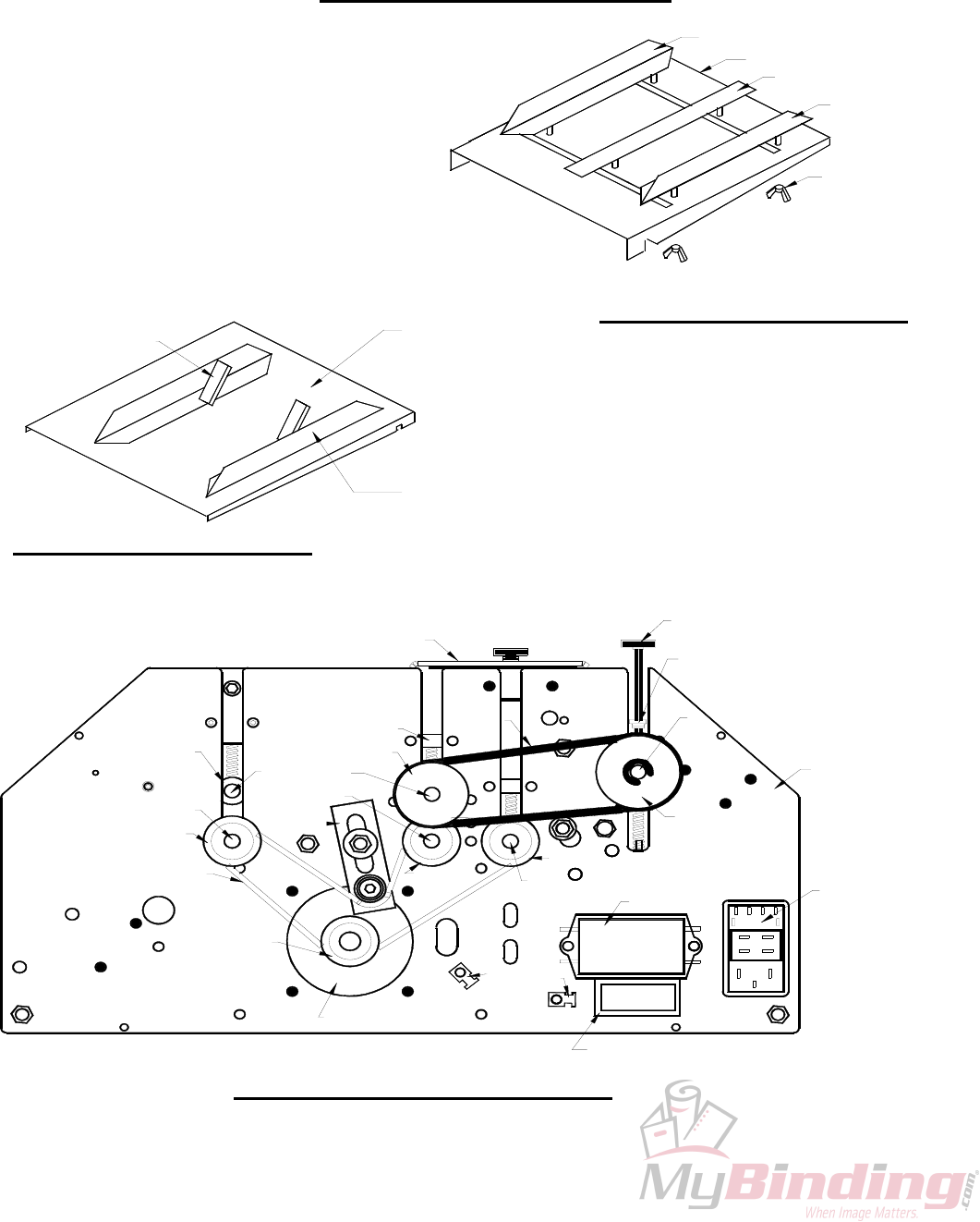
8.0 PARTS DIAGRAMS
90-015-GW
10-055-GW
10-056-GW
40-003-GW
90-024-GW
8.3 GW 3/6/8000 OPERATOR SIDE
40-103-GW
50-021-GW
90-005-GW
10-030-GW
10-031-GW
40-003-GW
50-009-GW
50-023-GW
90-010-GW
10-026-GW
50-022-GW
8.2 EXIT TRAY ASSEMBLY
10-057-GW
50-014-GW
90-063-GW
90-082-GW
90-031-GW
40-003-GW
90-062-GW
30-025-GW
10-022-GW
10-023-GW
10 026-GW
90-002-GW
8.1 FEED TRAY ASSEMBLY
10-018-GW
10-020-GW
10-019-GW
10-018-GW
10-017-GW
43
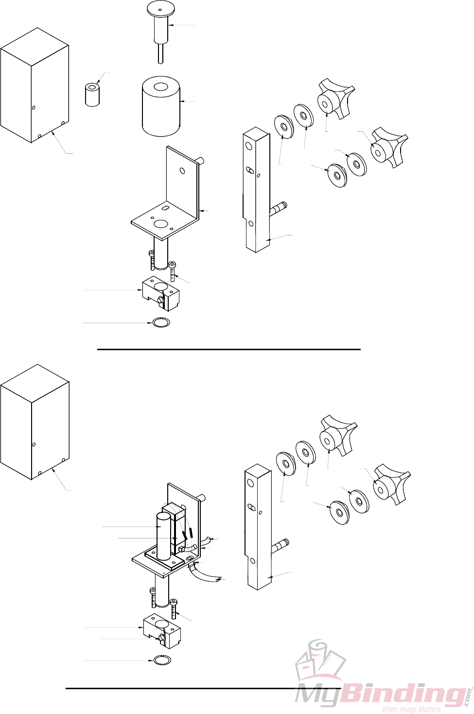
90-054-GW
10-043-GW
10-044-GW
15-052-GW
8.4 ELECTRIC SOLENOID DRIVE UNIT (15-072-GW)
10-011-GW
10-054-GW
10-053-GW
50-040-GW
15-039-GW
10-040-GW
10-042-GW
10-041-GW
January 1997
90-054-GW
10-071-GW
15-052-GW
8.5 PNEUMATIC SOLENOID DRIVE UNIT (94-072-GW)
10-045-GW
BLACK
RED
10-011-GW
10-054-GW
90-055-GW
10-046-GW
GREE
YELLW
10-053-GW
15-039-GW
96-070-GW
10-050-GW
10-040-GW
10-042-GW
10-041-GW
44
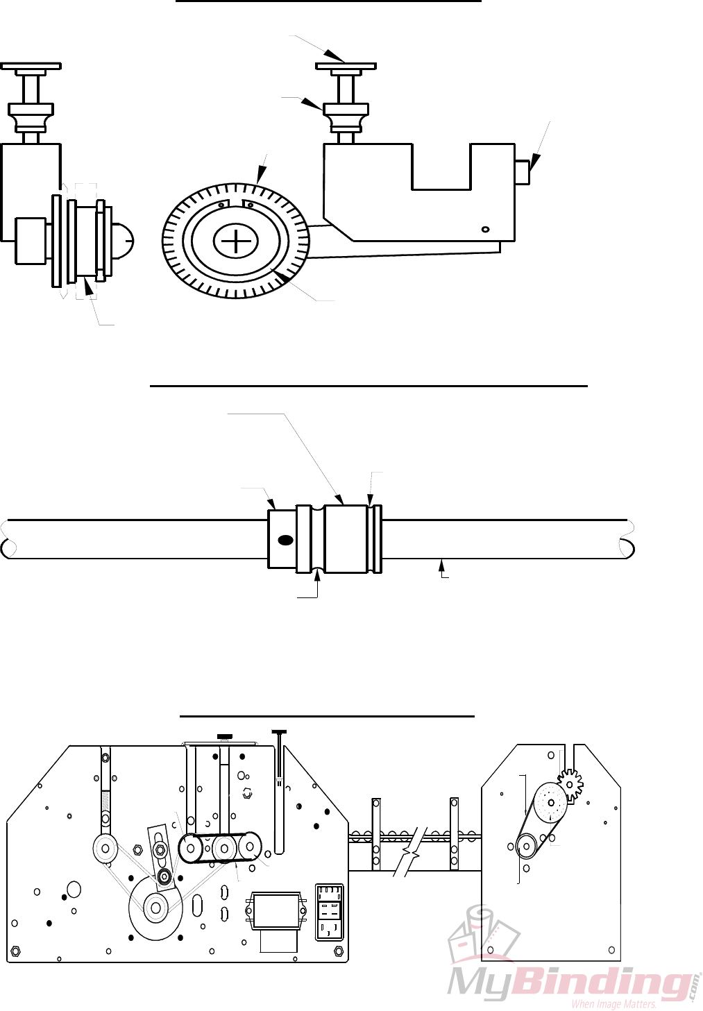
Pressure Adjustment Screw
(10-085-GW)
Locking Thumbnut
(10-023-GW)
8.6 ACCESSORY HOLDER
Blade Hub
Perf/Slit/Score Blade
(10-095-GW)
3/4 '' Snap Ring
(10-011-GW)
Position Locking
Set Screw
(
15-038-G
W
Perf & Slit Blades Ride On The
Flat Surface Of The Boss Wheel
8.7 Blade Placement on the Boss Wheel
Regular Score Blade Rides
In This Groove
Boss Wheel
(10-090-GW)
Boss Wheel Shaft
(50-014-GW)
Narrow Score Blade Rides
In This Groove
96-019-GW
70-008-GW
70-008-GW
60 011-GW
30-027-GW
70-008-GW
70-007-GW
8.8 GW 12000 FEED DRIVE COMPONENTS
45
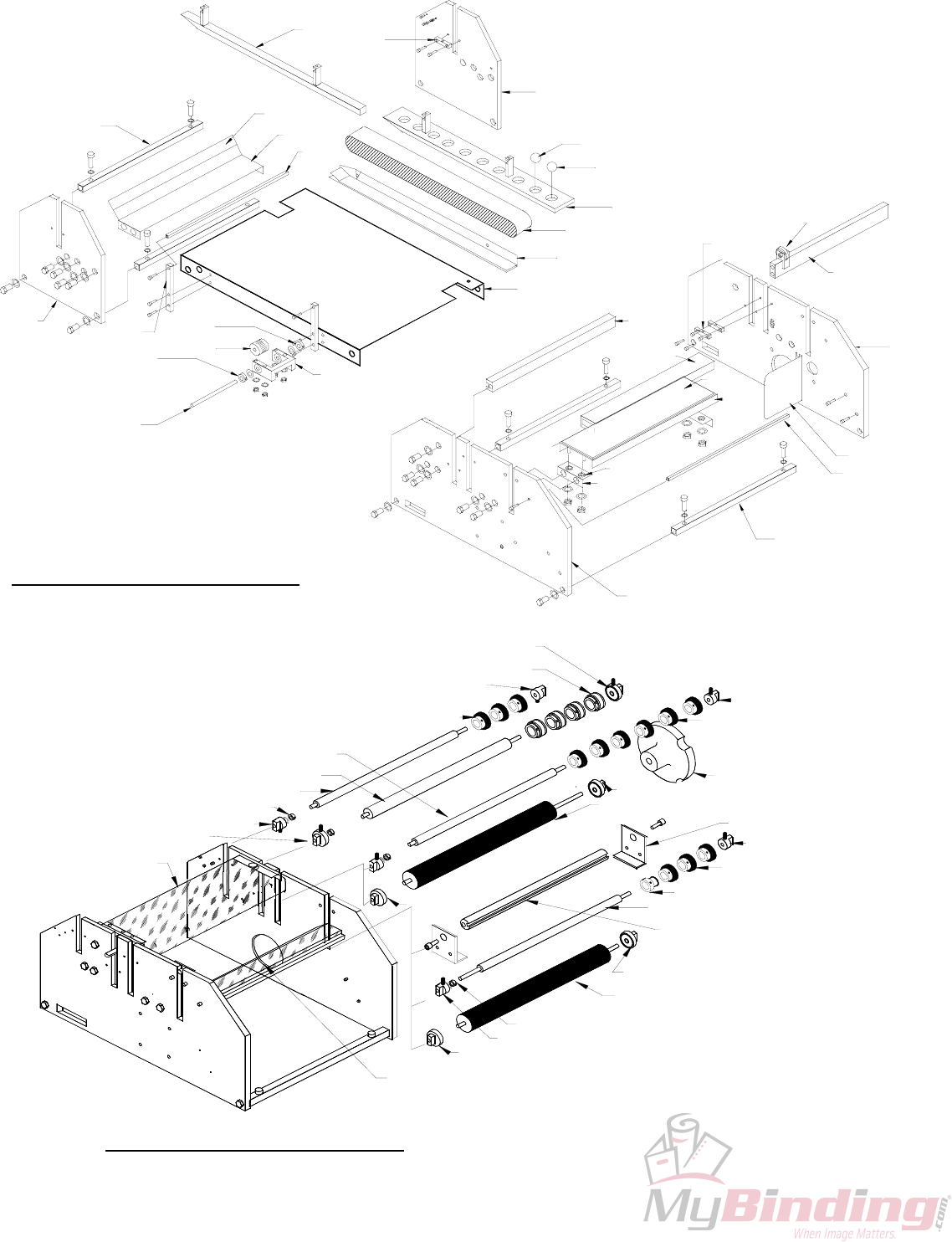
10-030-GW
10-027-GW
10-029-GW
10-090-GW
10-030-GW
50-020-GW
10-029-GW
10-029-GW
8.10 GW 3/6/8000 Shaft Placement
10-026-GW
10-027-GW
10-029-GW
50-014-GW
10-026-GW
10-030-GW
90-015-GW
10-024-GW & 10-025-GW
10-025-GW
10-031-GW
10-026-GW
15-036-GW
10-029-GW
50-011-GW
10-058-GW
10-024-GW & 10-025-GW
10-024-GW & 10-025-GW
10-029-GW
50-010-GW
10-030-GW
10-030-GW
70-003-GW 96-017-GW 10-027-GW
96-023-GW
10-027-GW
8.9 GW 12000 Structural Parts Diagram
60-007-GW
96-018-GW
50-017-GW 70-006-GW
50-019-GW
96-024-GW
10-021-GW
50-019-GW
50-009-GW
10-032-GW
10-035-GW
90-001-GW
10-034-GW
90-082-GW
90-012-GW
50-019-GW
90-007-GW
50-019-GW
10-033-GW
90-002-GW
70-015-GW
96-012-GW
96-025-GW
70-014-GW
96-013-GW
96-009-GW
70-003-GW
94-013-GW
94-014-GW
46
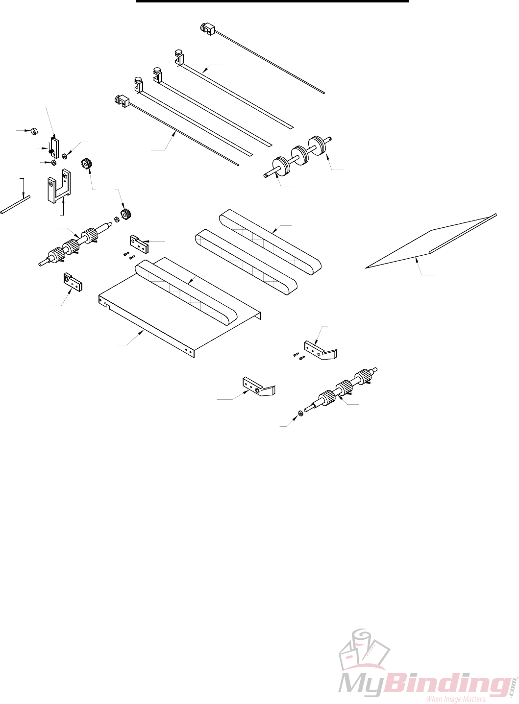
60-004-GW
60-014-GW
8.11 Conveyor Outfeed Assembly
60-007-GW
60-001-GW
60-003-GW
60-008-GW
10-026-GW
60-017-GW
60-017-GW
60-017-GW
60-005-GW
10-027-GW
60-016-GW
60-002-GW
60-016-GW
60-012-GW
60-009-GW
10-027-GW
90-014-GW
60-015-GW
60-011-GW
10-027-GW
50-018-GW
60-013-GW
10-026-GW
60-017-GW
60-017-GW
60-006-GW
47

48
