MyBinding Ideal 3905 3915 Blade Change User Manual
2013-06-04
User Manual: MyBinding Ideal-3905-3915-Blade-Change
Open the PDF directly: View PDF ![]() .
.
Page Count: 7

3905/3915 Knife Change
CAUTION: Disconnect the power cord from the outlet (3915) and
maintain control of the power plug throughout this procedure. If the
machine is hardwired to the electrical supply , turn off the circuit
breaker and lock it out with a padlock through out this procedure.
CAUTION: KNIVES ARE VERY SHARP
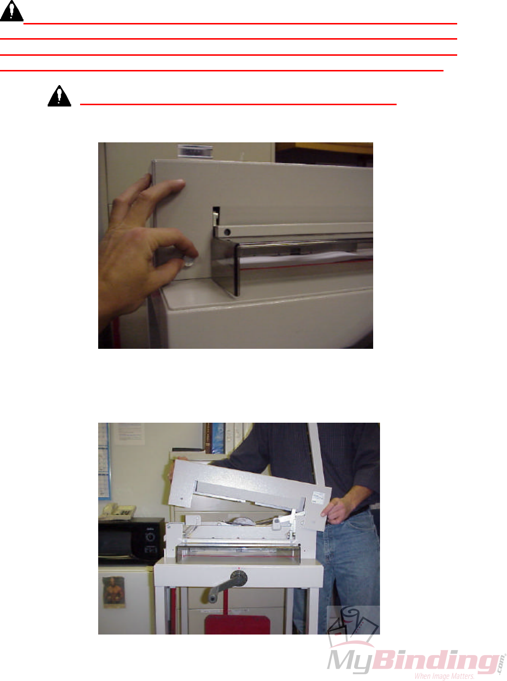
1. Remove the two Cover Screws on the far left and right. See Figure 1.
Fig. 1
2. When removing Covers, make sure the Cut Handle is in vertical position and Safety
Guard is down. See Figure 2.
Fig. 2
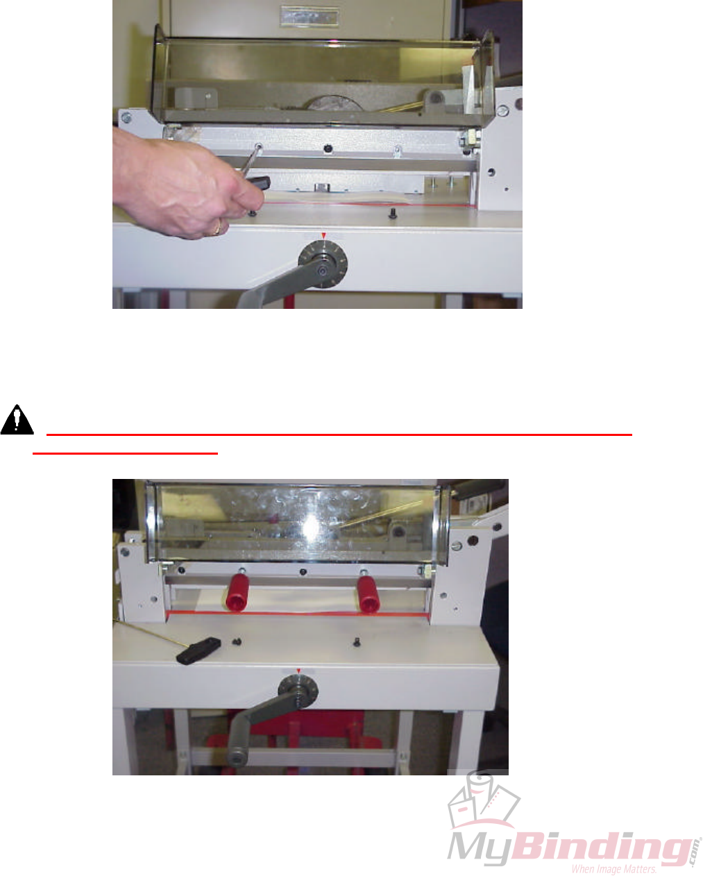
3. Once the Cover is removed, raise the Knife to the full top position (swing Handle all
the way to the right when standing in front of the Cutter until Safety Latch clicks.)
Remove the two center Screws on the Knife using the metric Allen found in your
tool kit. See Figure 3.
Fig. 3
4. Once both center Screws are removed, locate the 2 red Handles in your tool kit and
screw them clockwise into the holes until they are tight. See Figure 4.
CAUTION: Only the Handles will be holding up the Knife when the remaining
three Screws are removed. Remove the remaining three Screws.
Fig. 4
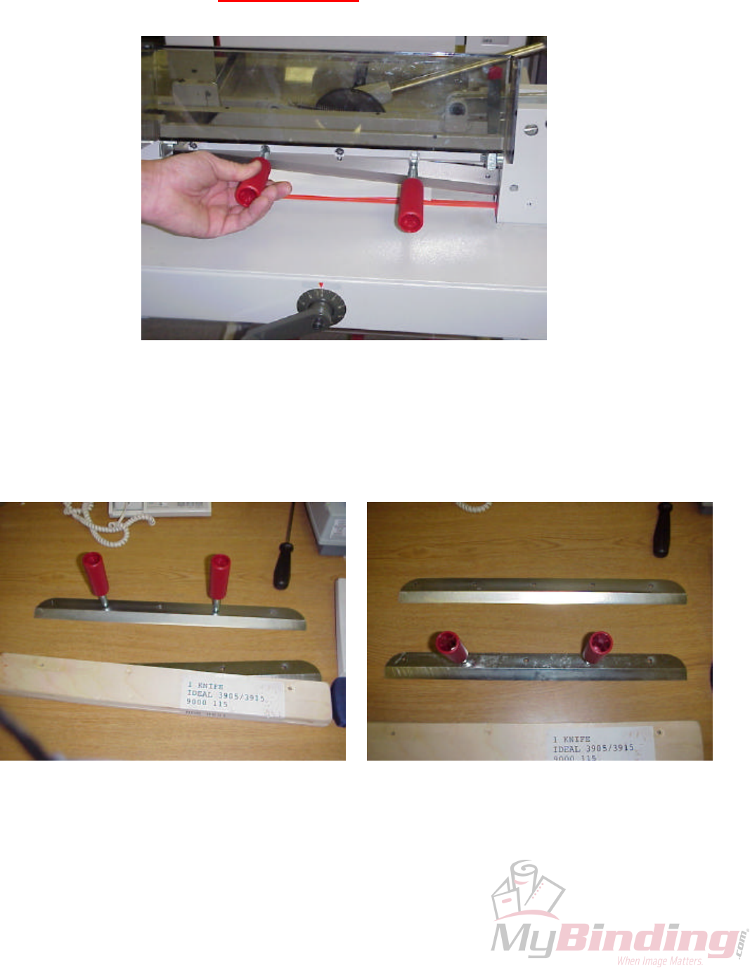
4. Grasp both Handles firmly and loosen the Handles (turn Counter-Clockwise). It
may take 2 or 3 full turns before you feel the Knife start to slide out of the Knife
Carrier. Remember KNIFE IS SHARP! When the Knife is free from Carrier, move
the Knife slightly to the right and remove from the left. See Figure 5.
Fig. 5
5. Once Knife has been removed, place it on a flat surface away from the Cutter where
you have room to unpack the new or re-sharpened Knife. See Figure 6. Remove the
Handles from the dull Knife and screw them into the exact same holes in the new
Knife as shown. See Figure 7.
Fig 6 Fig 7
6. Pick up the new Knife BY THE HANDLES and insert the Knife back up into the
Carrier. If the Knife will not go all the way up, it may be necessary to loosen the
Handles a couple of threads so the Knife will slide into the Knife Carrier evenly.
Once the Knife is all the way up into the Carrier, you can turn the Handles tightly
(Clockwise) to hold the Knife in place. Replace the three Screws and make sure they
are tight so the Knife won’t drop down. At this point, remove the Handles and
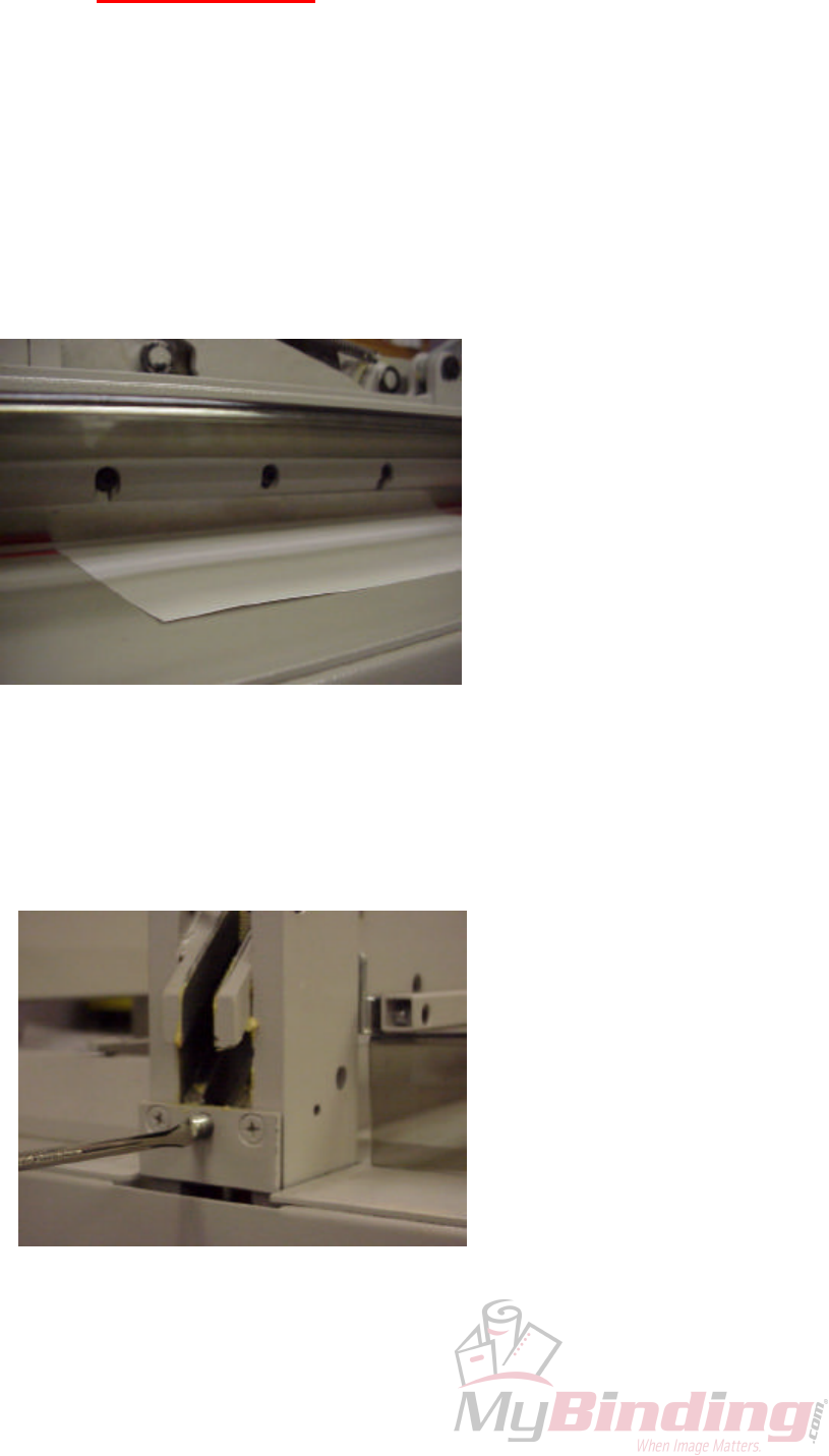
replace with the two remaining Screws, making sure they are tight. Lay a sheet of
11” X 17”, or two 8-1/2” X 11” sheets of paper over the unused side of the Cut Stick.
Use Clamp Handle on the machine to clamp the paper down and trip the Safety
Latch. Bring the Knife Carrier down slowly, while watching and making sure that
when the Knife is at it’s lowest point, there is clearance between the Knife edge and
the paper. See Figure 8.
Fig. 8
7. If there is no clearance, or the paper begins to cut before the Handle is all the way
down, a Knife Carrier adjustment is needed. This adjustment is on the left side of
the Knife Carrier. You can turn the Screw clockwise to raise the Knife Carrier, and
counter-clockwise to lower the Knife Carrier. Either way you make the adjustment
you can watch the movements by getting eye level with your work and watching as
you make the necessary adjustments. See Figure 9.
Fig. 9

8. With Knife Handle in its lowest position turn Adjustment Screw until the Knife cuts
thru the entire sheet. Once this has been achieved try to cut a lift of 50 – 100 pages
making sure all pages are cut. See Figure 10.
Fig. 10
3905/3915 Knife Carrier / Tower Adjustment
1. There may be circumstances where the paper will cut at a slant. You will more
than likely find this on the manual clamp cutters (i.e. 3905/3915). If this
happens, the first thing you should check is your paper clamp pressure by
clamping 2 sheets of paper and trying to pull them out. If the paper cannot be
pulled from under the clamp it will be necessary to perform a tower
adjustment.
Fig 1
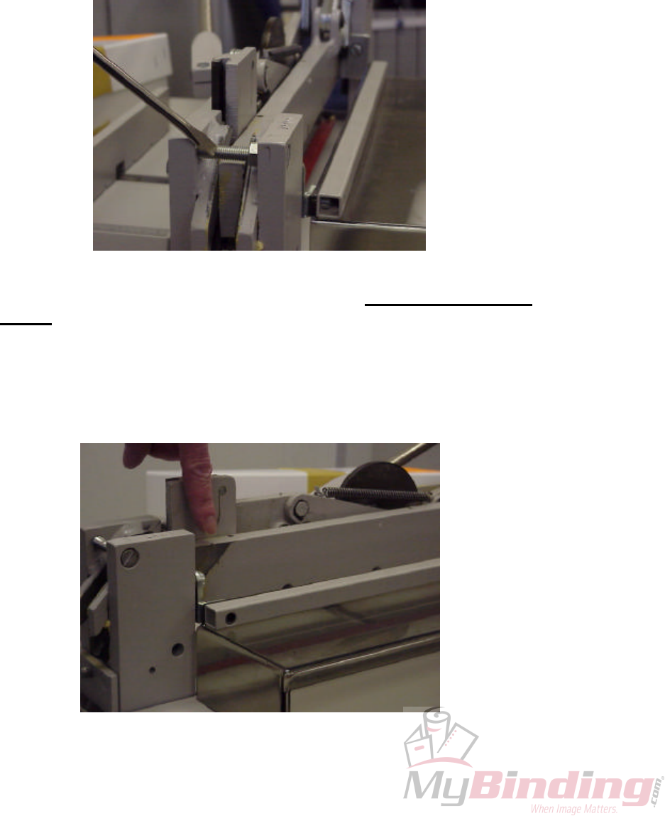
2. To check the knife carrier for a rocking motion you MUST REMOVE THE
KNIFE and rock the top and bottom of the carrier. If you feel a slight rocking
motion/slop, tighten the tower adjustment screw one or two threads at a time
until movement stops (shown in Fig.1). In some cases this movement is caused
by worn or non-lubricated towers. If this is noticed, lubricate the carrier
shown in Fig 2 on the left and right sides. In the case where the towers are
worn, the machine is considered irreparable.
Fig 2
