MyBinding Isp 305 305G Manual User
2013-06-04
User Manual: MyBinding Isp-305-305G-Manual
Open the PDF directly: View PDF ![]() .
.
Page Count: 47


MODEL
305
305-G
OWNERS
MANUAL
For Models With M2000 Stitching Heads
Bindery Mate Serial Numbers
5161 and higher
ISP
Stitching & Bindery Products
A Division Of Samuel Strapping Systems
Section 1 INTRODUCTION
1. Model and Serial Number
2. Product Specifications
Section 2 SAFETY PRECAUTIONS
AND PROCEDURES
4. Safety
4. Safety Guards/Cover
Section 3ASSEMBLY,
LUBRICATION,
INSTALLATION
5. Before Unpacking
5. After Unpacking
5. Assembly
6. Threading wire and adjusting wire
straightners
7. Lubrication-Felt Pads
8. Lubrication-Stitcher Head
9. External Lubrication
10. Internal Lubrication
Section 4OPERATION
11. General Stitching
11. Table/Saddle Conversion
11. Table Stitching Using Work Trip
11. Table Stitching Using Foot Trip
11. Stitch Repeat
11. Hand Jog
12. Master and Secondary
12. Saddle Stitching-Foot Switch Only
12. Work Guides:
Side Guides
Corner Stitch Guides
12. Changing Work Thickness
Section 5 MAINTENANCE, TROUBLE
SHOOTING AND ADJUSTMENT
13. General
13. Recommended Spare Parts
13. Cleaning and oiling
13. Stitching Adjustments
13. To Equalize Both Legs of Stitch
14. Trouble Shooting-M2000 Head
17. Trouble Shooting-Drive
20. Insufficient or Excessive Compression
20. Table/Clincher Bracket Adjustment
20. Clincher
21. Clincher Point Height Adjustment
21. Reversing or Replacing Clincher Points
22. Head/Clincher Alignment
22. Bender bar
22. Bender bar Friction Plug
23. Driver Bar
24. Bender Bar Latch
24. Grip, Grip Release Slide and Faceplate
25. Wire Cutters
26. Wire cutter Operating Slide
26. Proper Wire
26. Rotator
27. Wire Straighteners
28. Supporter
28. Tension Pawl
28. Work Trip
29. Stitcher Head Disassembly
31. Drive/Frame Disassembly
Section 6PARTS LIST
35. Drive/Frame
40. M2000 Head Stitcher
Section 7ELECTRICAL
42. Electrical Schematic (115 V.A.C.)
43. Electrical Schematic (230 V.A.C.)
CONTENTS
USE REPLACEMENT PARTS
DESIGNED AND
MANUFACTURED ONLY BY
INTERLAKE SPECIFICALLY FOR
YOUR M2000 STITCHER

1
Section 1
INTRODUCTION
MODEL 305, 305-G
BINDERY MATE
Your stitcher with the M2000 Stitching Head has been engineered and developed to provide you with the
finest equipment available for your stitching needs. With proper care and maintenance it will give you years
of satisfactory efficient service. This manual shows you how to get top performance from your stitcher and
is divided into 7 major sections.
Read the Bindery Mate Manual throughly. Study it carefully. Best stitching performance will be assured,
if all the adjustments are made as instructed, so that you get the following desired results.
1. Good Cut-Off
2. Uniform wire draw
3. Equal leg length
4. Proper clincher alignment
5. Sufficient compression
When ordering parts or requesting information, please state: Quantity required, part number, part
name, model and serial number of your stitcher.
Bindery Mate Serial Number____________________
Bindery Mates M2000 Head Stitcher Serial Number____________________
Here are the instructions on
how to install
operate, maintain, and make
repairs on your

2
BINDERY MATE
PRODUCT SPECIFICATIONS
Unit Weight: Overall: 30 Lbs.
Without Wire Spool: 25 Lbs.
Unit Envelope Size: Height Length Width
Overall: 27" 15" 10"
Without Tables and Wire Guide: 22" 12 1/2" 4"
Wire (Interlake 417-0025)
Wire Material: 120,000 to 150,000 p.s.i. tensile strength
tinned steel wire
Wire Size: 25 Gauge (.020" Diameter)
Wire Spool Weight: 5 Lb. Spool (Fully Loaded Wire)
Stitching Speed 173 stitches per minute, full load capacity.
199 stitches per minute, minimum load
capacity.
Stitching Capacity (20 Lb. Bond Paper)
Minimum Stitching thickness adjustment .94" Wire Draw, Approx. 57,000 stitches
per 5 Lb. coil.
Maximum Stitching thickness adjustment 1.24" Wire Draw, Approx. 43,000 stitches
per 5 Lb. Coil.
Maximum Stitching thickness: 1/4"
Stitcher: M2000 Head CTTT-2605-T3
(Equipped with faceplate adjustment lever)
Table (Flip-Up)/Saddle (Flip-Down)
Length: 10"
Width: 4 3/4"
Side Guides: Pop-Up/Pop Down pins in arms which adjust from 7/8" to 9 5/8" from center of clincher.
Corner Guides: Pop-Up/Pop Down pins in table for 45 degrees corner stitch.
3
BINDERY MATE
PRODUCT SPECIFICATIONS
Auxiliary Rear Table (For flat work support when deep throat table stitching)
Length: 10"
Width: 3"
Throat Depth: 4" Max.
Stitch Modes:
Work Trip (For Table Mode): Plug foot switch into rear of housing.
Foot Trip (For Saddle or Table Mode): Manual Switch Control.
Master-Secondary (For use with Plug master into 2nd-3rd units for
multiple stacked unit): side by side multiple stitch (4 1/2 in.
min. centers).
Quick adjust for 3/16" to 4" throat depth.
Jog: Push in and turn knob, on rear of housing,
for manual forward or reverse operation.
Electrical
Input: 115 V.A.C. 60 HZ 230 V.A.C. 50 HZ
(Model 305) (Model 305-G)
Control Circuit: 12 V.D.C. 12 V.D.C.
Motor: 1/20 HP, 90 V.D.C. 1/20 HP, 180 V.D.C.
Circuit Breakers: 1 AMP for 115 V.A.C. Input 1/2 AMP for 230 V.A.C. Input
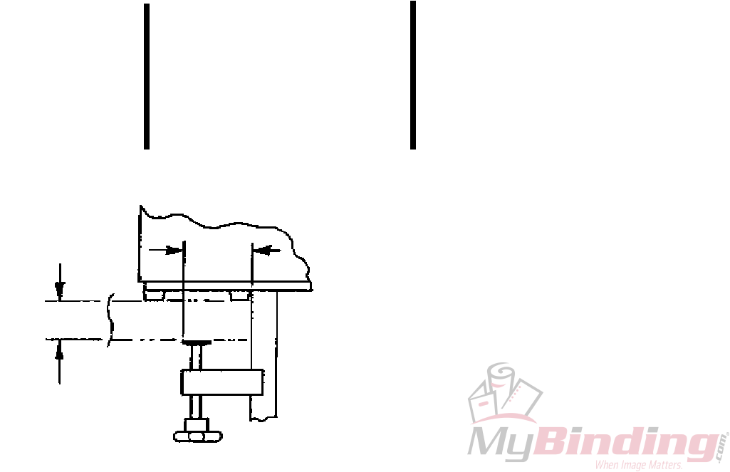
Mounting:
2 3/4"
Table
2 1/2" Max
1/2" Min
4
CAUTION
Do not operate stitcher until operating
instructions have been read and understood-
do not operate stitcher at anytime without
work under the head.
CAUTION
FOR YOUR SAFETY, MAKE SURE ALL
COVERS ARE PROPERLY IN PLACE
BEFORE OPERATING MACHINE
DANGER
KEEP HANDS CLEAR OF
STITCHING AREA
CAUTION
THE SUPPLY CIRCUIT FOR ANY
305/306 SERIES UNIT MUST USE A
15 AMP MAXIMUM FUSE OR
CIRCUIT BREAKER. THE SHORT
CIRCUIT CAPACITY OF THE
SUPPLY CIRCUIT MUST NOT
EXCEED 2000 AMPS.
Section 2
SAFETY PRECAUTIONS
AND PROCESURES
SAFETY
1. Make sure electrical power is turned off before
performing any adjustment or maintainence.
2. Keep hand, tools, hair, and clothing clear of
stitching area.
3. Become familiar with the moving components of
your machine. Keep fingers away from areas
that could pinch or cut.
4. Observe your plant safety rules.
5. Exert good housekeeping in your work area.
Keep it as clean and uncluttered as possible.
6. A well maintained machine is a safer machine.
Clean and lubricate the machine at regular
intervals. Check machine daily for broken or
worn parts. Replace as necessary. DO NOT
attempt to operate the machine if a part is broken.
7. Route all electrical cables away from pedestrian
transportation lanes.
8. See Safety Guards/Cover information. It points
out areas where additional caution should be
exercised. If you are unsure how to safely operate
or maintain your Stitcher, contact your Service
Representative.
SAFETY GUARDS/COVER
A. Grey Plastic Cover: Covers frame, motor,
mechanical, and electrical components.
B. Front, Clear Plastic, Guard Assembly: A three
position guard. In the fully downward position
the guard is spring loaded to: cover the M2000
Head, and work trip adjustment knob; restrict
access to the stitching area; depress a limit
switch to allow the machine to operate. The
guard can be swung up to its first detent position
(about 70 deg.) to allow access to the work trip
adjustment knob and lower portion of the M2000
Head. The guard is swung up to its second
detent position (about 155 deg.) to allow total
access to the M2000 Head for faceplate
adjustment, lubrication, and wire threading.
ATTENTION
LE CIRCUIT D'ALIMENTATION DESTINE
A UNE UNITE DE LA SERIE 305/306 DOIT
COMPORTER UN FUSIBLE OU UNE
PROTECTION THERMIQUE CALIBREE A
15 AMP MAXIMUM. LA CAPACITE DE
COURT CIRCUIT DU RESEAU NE PEUT
PAS DEPASSER 2000 AMPS.
5
Section 3
ASSEMBLY, LUBRICATION
INSTALLATION
Note:
These instructions must be followed to insure
proper installation, efficient operation and the
prevention of serious damage to your stitcher.
Before Unpacking:
Examine the outside of the crate or carton for any
visible damage. If damaged DO NOT UNPACK
THE STITCHER. Notify the carrier who delivered
the stitcher.
After Unpacking:
Examine your stitcher carefully for any damage in
transit. If damaged, DO NOT INSTALL THE
STITCHER. Notify your nearest representative and
the carrier who delivered your stitcher.
Make certain that you get a signed copy of the Carrier
Inspectors Report of the damage incurred
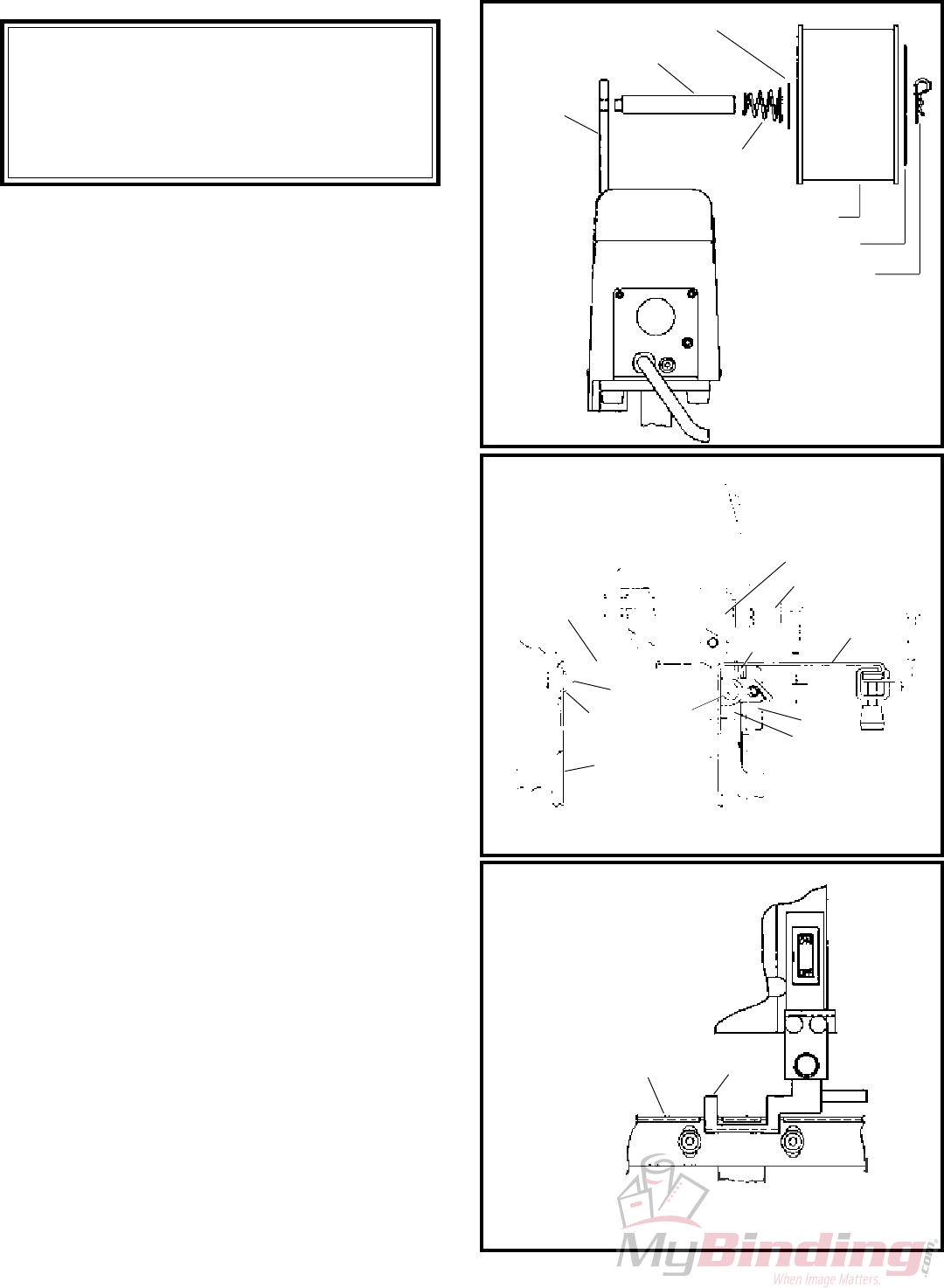
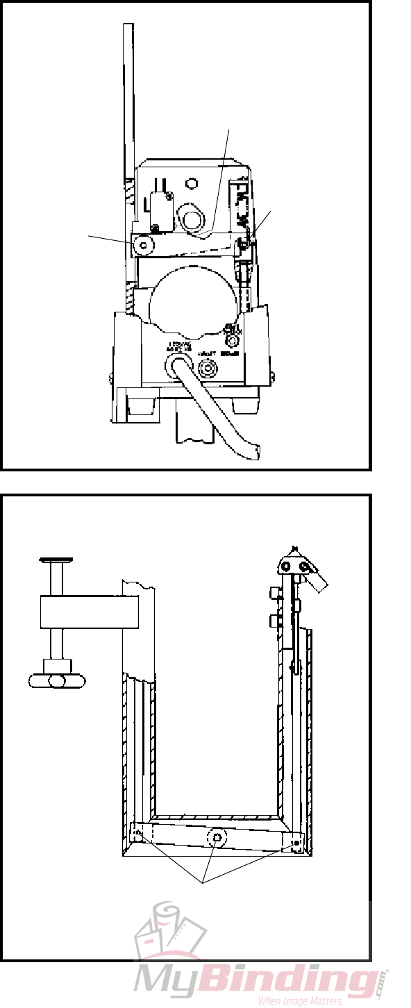
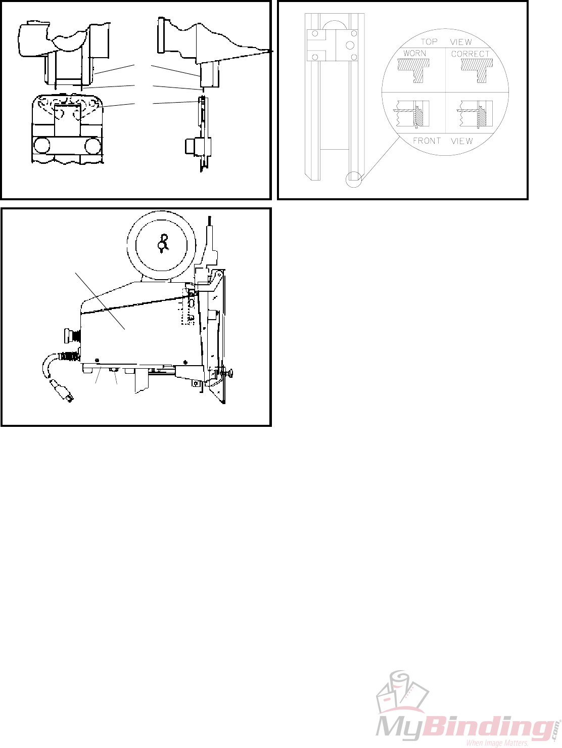
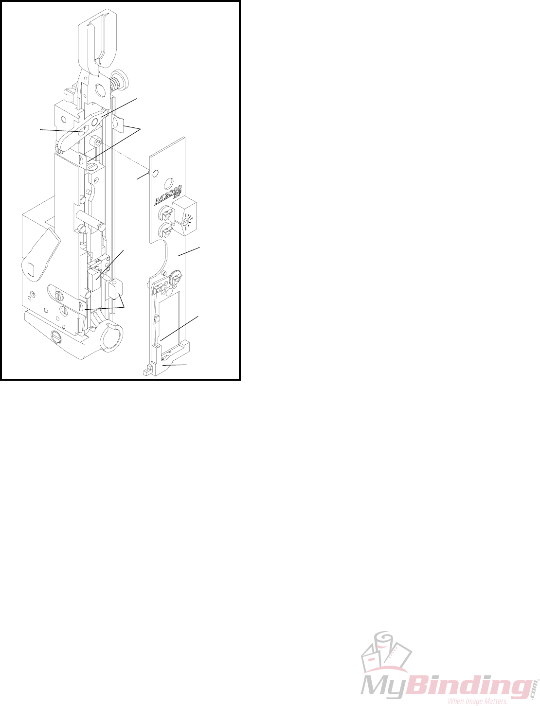
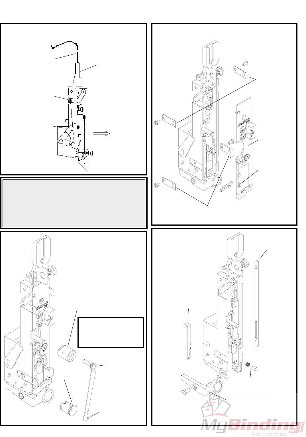
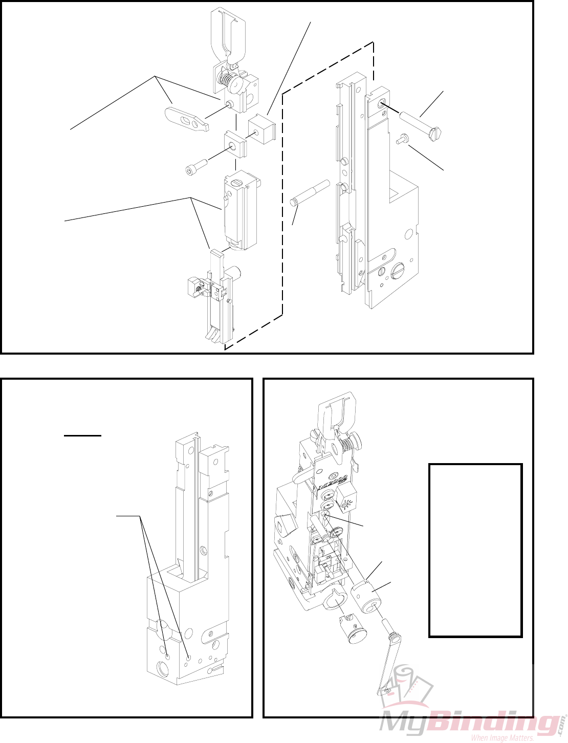
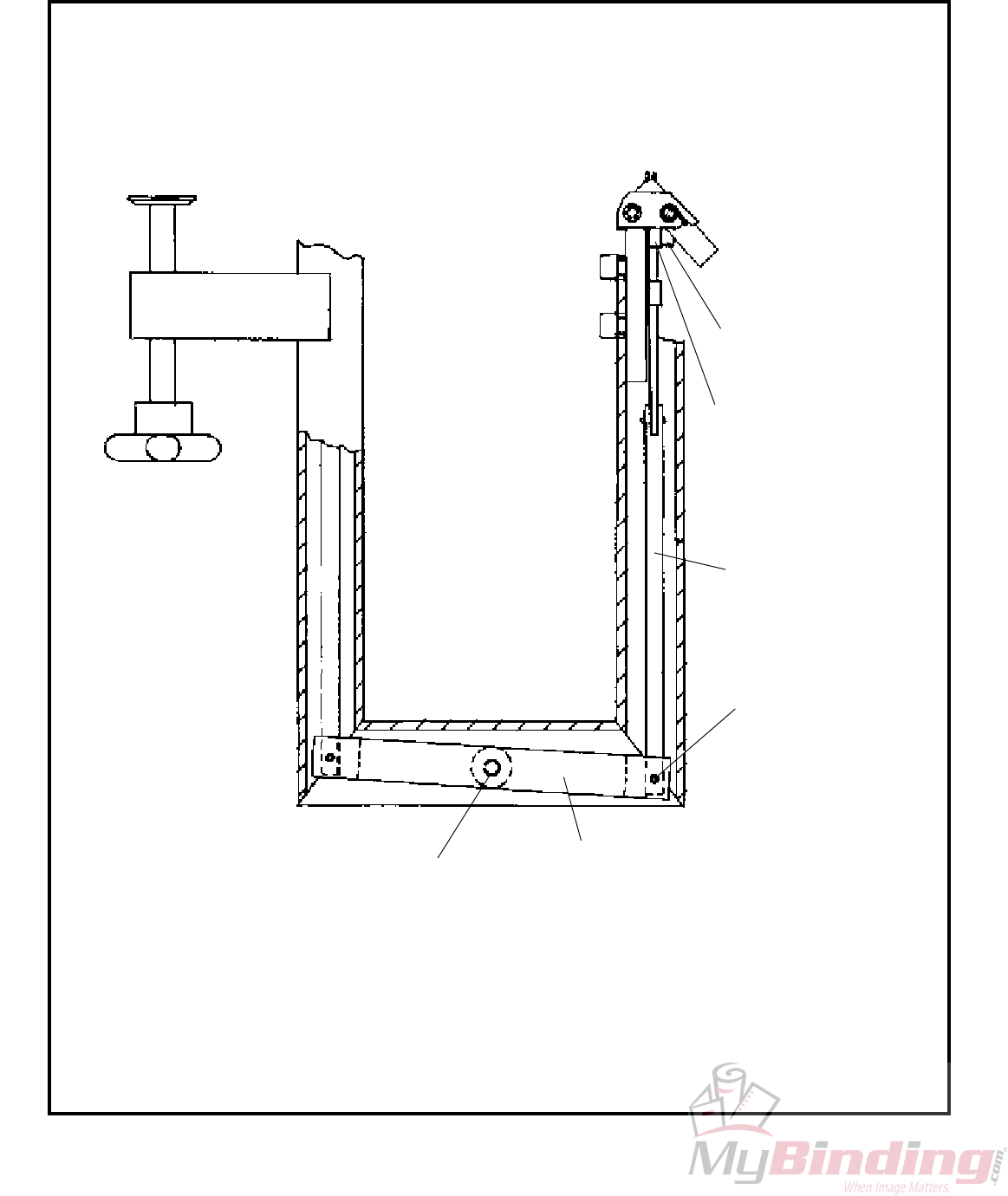
ASSEMBLY (FIGURES 1,2,3)
1. Clamp the Bindery Mate to a table or bench (see
"Mounting" page 3). Assemble per figure 1.
2. Install Table/Saddle (Index A) to Table and
Clincher Bracket (Index B) using the two
shoulder screws (Index C). Shoulder of screws
should extend through table and bottom out inside
of table/clincher bracket.
3. Turn Trip lever Knob (Index D) counter
clockwise and move the work trip (Index E) all
the way toward the clincher (Index F). Install
the Auxiliary Table (Index G) and Paper Guide
(Index K) to the stand using the two .25-28 x
.375 socket head cap screws and flat washers
(Index H,I). The top surface of the auxiliary
table should be at the same height as the main
table. NOTE: The auxiliary table MUST
NEVER TOUCH THE WORK TRIP OR
STITCHER WILL ACTIVATE (SEE
FIGURE 3).
4. Install Wire Guide Spring into wire guide bracket
of M2000 Head.
Wire Spool Washer
Wire Spool Stud
Support
Conical Spring
Spool Retainer
Coil of Wire
Hair Pin Cotter
NOTE: Slide coil of wire onto
spool stud so that the wire will
feed upward from the rear
NOTE: AUXILIARY TABLE "G"
MUST NEVER TOUCH WORK
TRIP "E"
Figure 1
(QF27F1)
Figure 2
(QF27F2)
Figure 3
(QF27F3)
A
E
D
B
J
K
I
H
G
GE
F
C
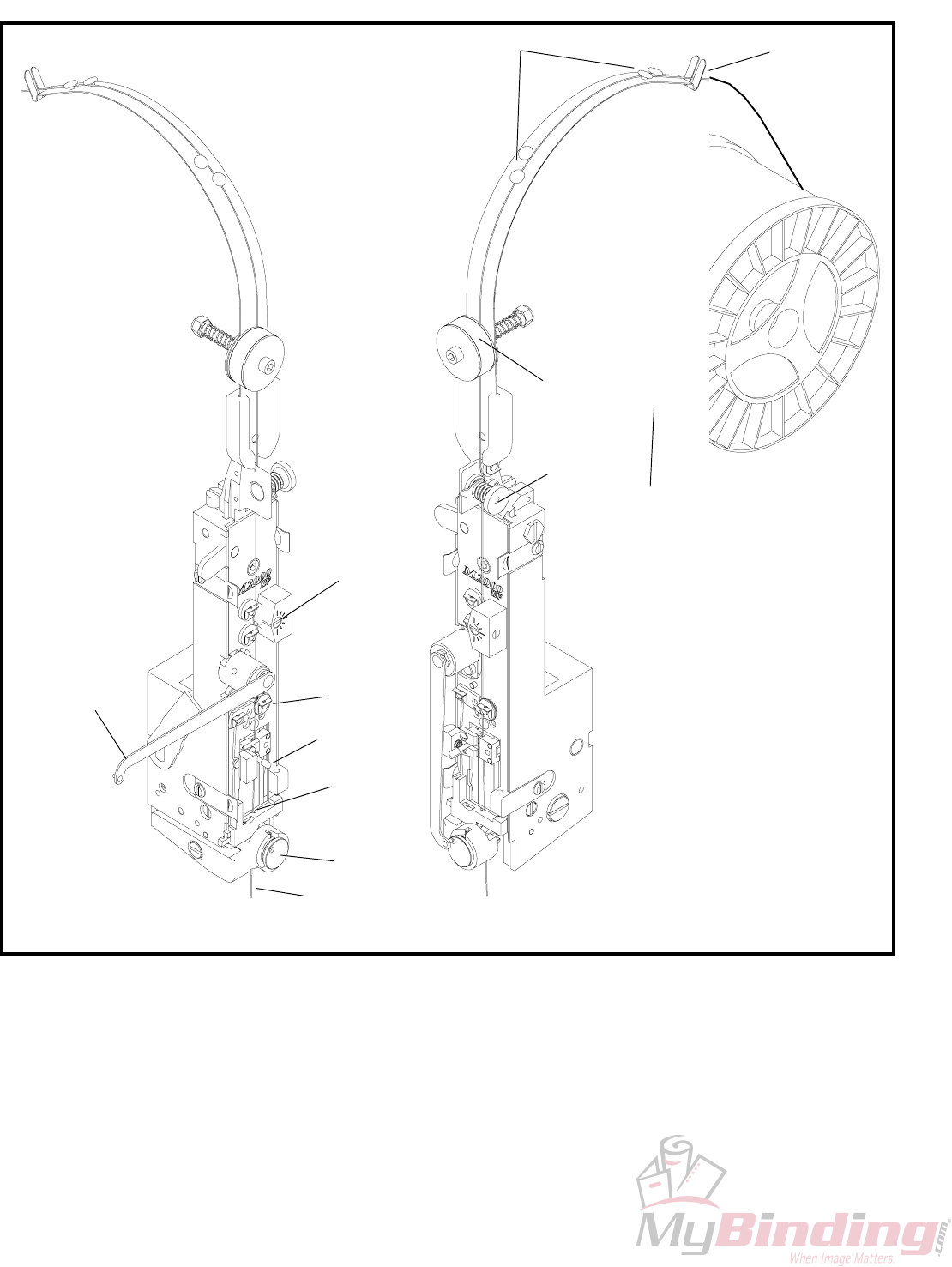
6
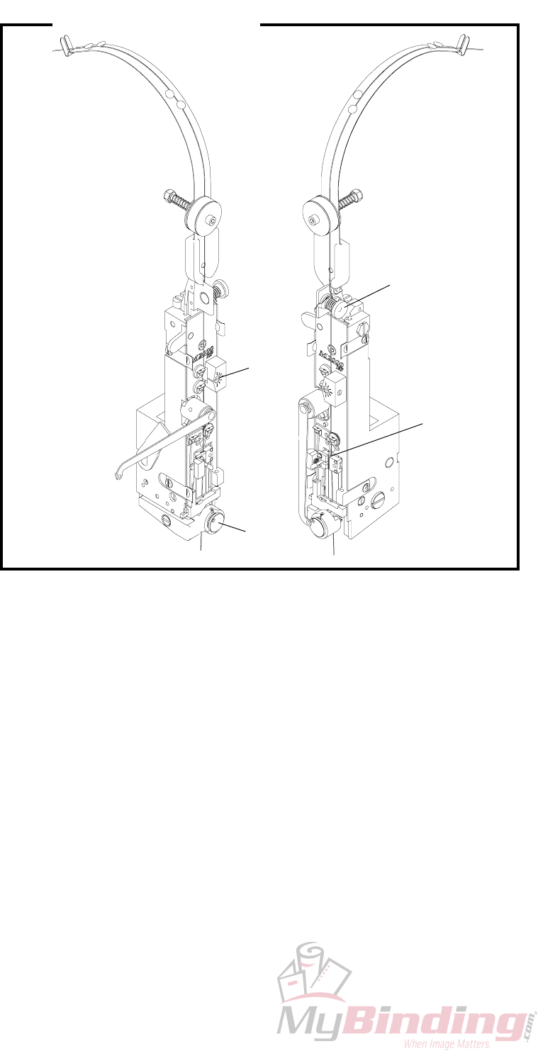
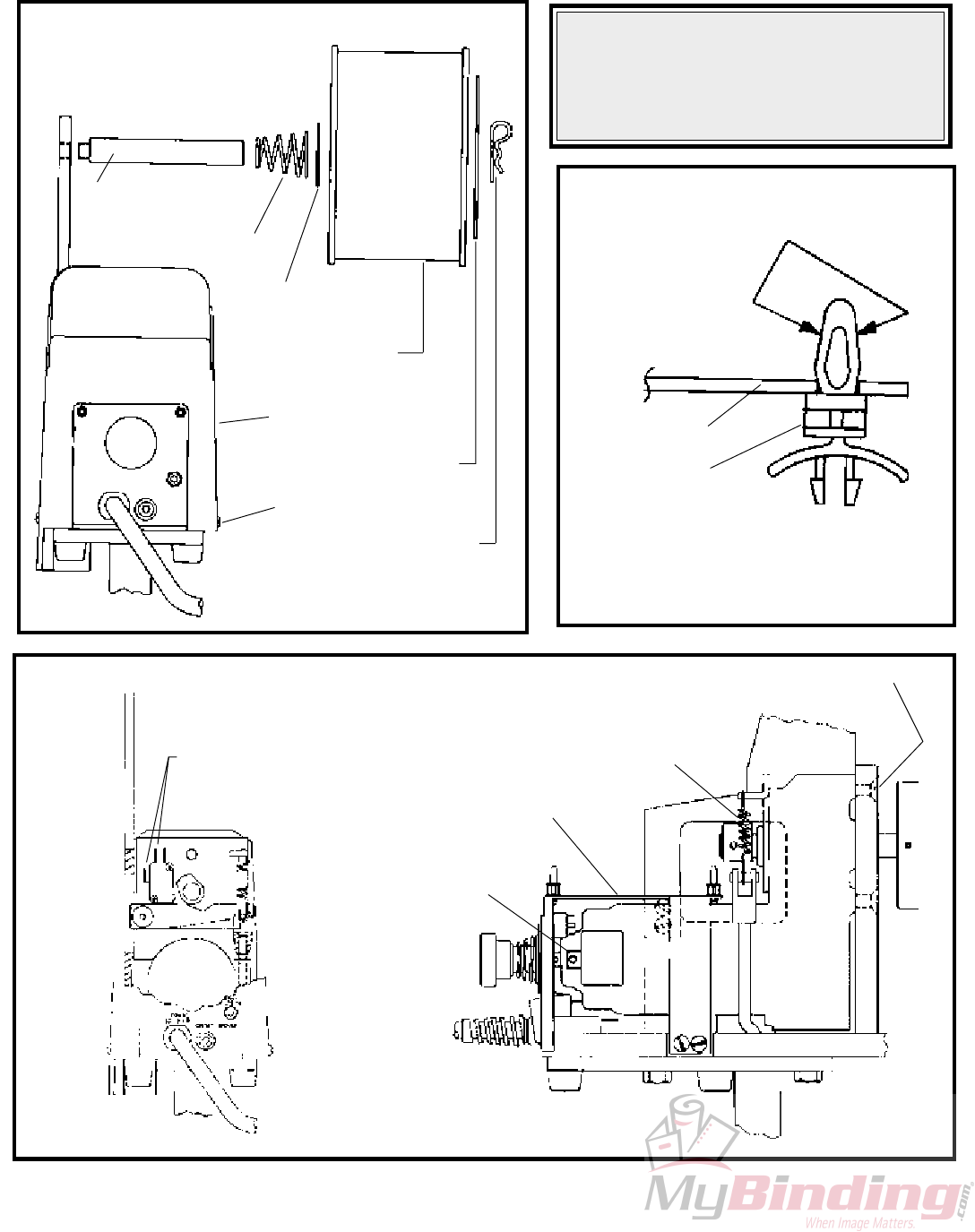
Figure 4
(CTTT2605T3 Scene 3, 4)
THREADING WIRE AND
ADJUSTING WIRE
STRAIGHTENERS (See fig. 4)
1. Draw wire by hand, from the the coil (Index A).
2. Thread the wire through the slot (Index B) at the
end of the wire guide spring, through the wire
guides (Index C), between the thin and thick felt
wire wipes (Index D), through the upper wire
straightener (Index E), and through the lower
wire straightener (Index F).
3. Release the rotator operating spring (Index H)
from the rotator and swing it to the left. Remove
Rotator (Index K).
4. Thread the wire between the tension pawl and
tension roll (Index G). Feed the wire through the
wire cutter lead-in hole (Index I) in the bottom
of the face plate.
5. Push grip post to left to open the grip (Index J).
Insert wire and release the post so that the grip
engages the wire for feeding into the rotator.
A
E
B
D
C
J
G
K
I
F
H
L
7
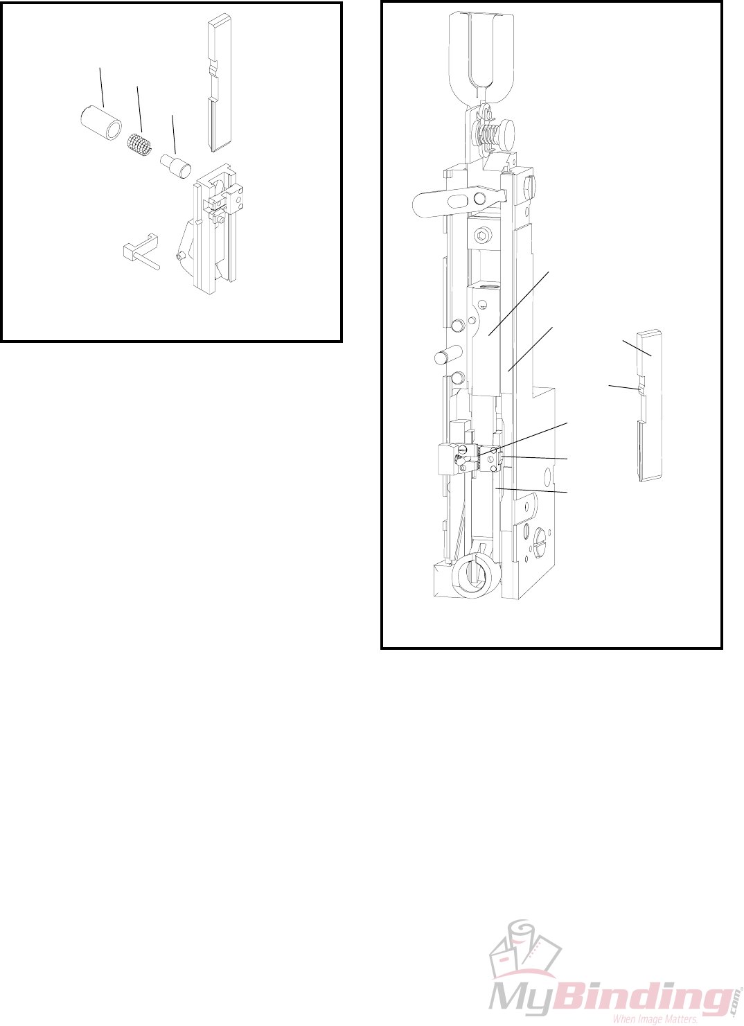
FELT WIPE PADS
LUBRICATION
AND MAINTAINANCE:
(FIGURE 5)
IMPORTANT! In order for the stitchers to operate
properly, the felt wire wipes MUST be rotated and
dampened with SAE 20W oil before each new
spool of wire (50,000 to 70,000 stitches). Replace
felt pads when they become so dirty that they cannot
be rotated to a clean spot.
6. To check adjustment, hold open grip (Index J
and pull about 1 1\2 feet of wire from below
face plate. Cycle machine once by hand to cut
wire. Cycle machine again by hand to observe
wire straightness. The wire (Index L) should
point straight down, prior to being cut, as shown
in Figure 4 .
7. Adjust the upper wire straightener, beginning at
position shown, (Index E, Figure 4) so that the
wire points straight down. Adjust the lower
wire straightener, beginning at the 3:00 o'clock
position, (Index F, Figures 4) so that the wire
(Index L, Figure 4) feeds straight down.
8. Replace the rotator and rotator operating spring.
NOTE:
When changing coils or wire sizes, check straightners
to insure proper wire feed.
Dirty area of pads has been
slightly rotated so that a clean
area of pads can be used for the
next wire spool.
1. After every wire
spool, rotate the dirty
area of the pads
slightly so that a clean
area can be used for
the next wire spool.
2. Dampen both pads
(about 30 to 40 drops)
using an SAE 20W
oil.
Rotate
Figure 5
(CTTT2605T3 Scene 5)
8
Typically, the 1/2 inch crown stitcher will run for
1,000,000 cycles without additional lubrication.
However, the following procedure used after each
spool of wire will assure optimum life and
performance. Use ISP lubricant #CA9640.
A. Inject lube into hole, or remove and lube shafts.
B. Wipe area clean and inject a small amount of
lube into cam area.
C. Remove rotator, wipe rotator clean and lube
rotator body.
D. Apply lube to rotator ramp.
E. Wipe clean inside of rotator holder.
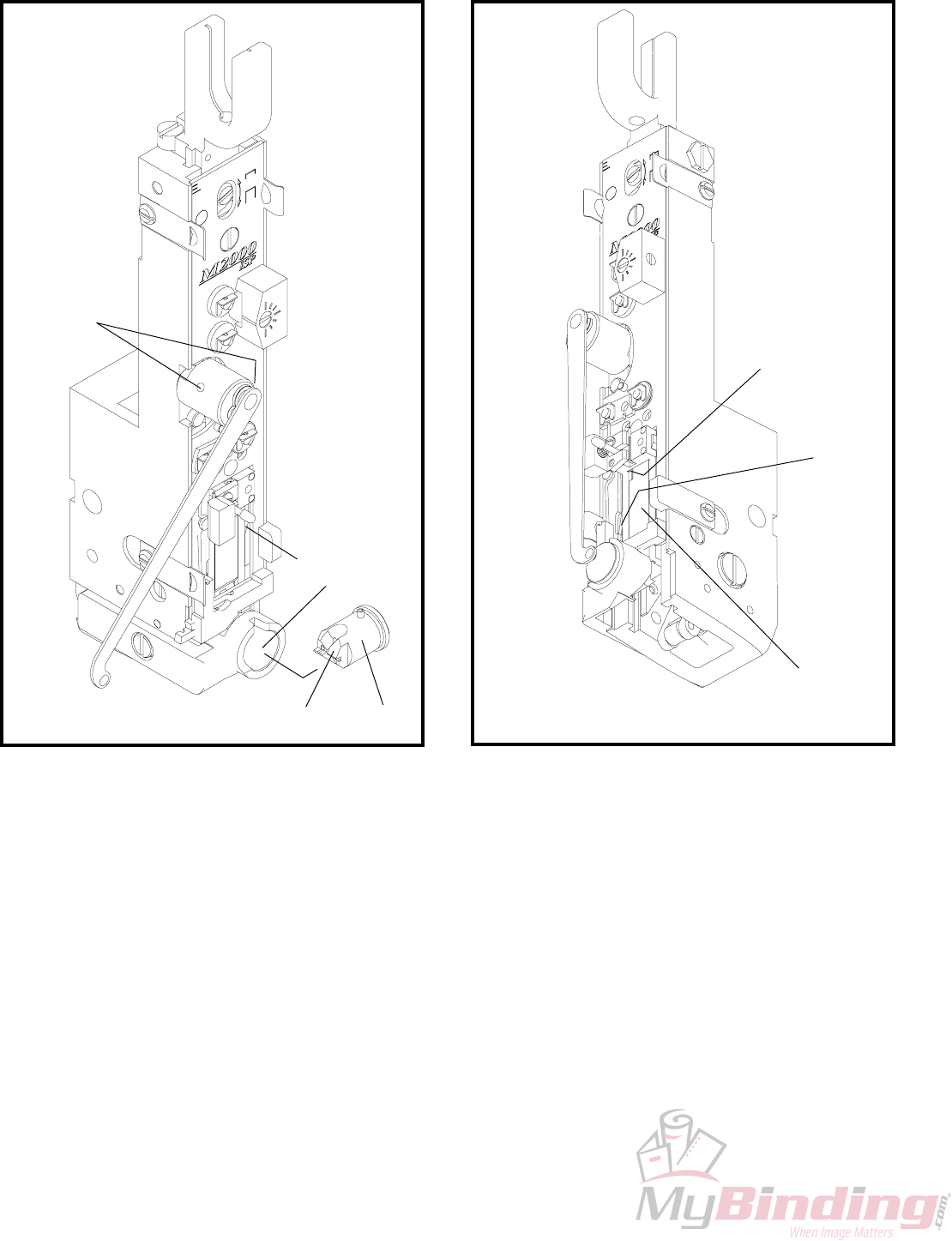
STITCHING HEAD
LUBRICATION:
(FIGURES 6 & 7)
Figure 6
(CTTT2605 Scene 5)
H
B
C
A
D
E
F
G
F. Inject a small amount of lube into cam area of
driver bar.
G. Inject lube into cutter operating slide.
H. Wipe driver clean, and apply a light coating of
lube.
After prolonged use (or storage) accumulations of
wire dust, dirt, or other contaminants can mix with
the stitcher lubricant. This will reduce the lubricant's
effectiveness. The following procedure is
recommended every 1,000,000 cycles.
1. Disassemble the head and clean all parts.
2. Lightly lube all sliding surfaces using ISP
lubricant #CA9640.
3. Double check lube points A through H.
Figure 7
(CTTT2605 Scene 6)
9
Lubricate the following points before each spool of
wire using SAE 20 oil.
L. One drop in top hole of head operating link.
Access through slot at top of cover behind stitcher
head.
M. One drop in lower/side hole of head operating
link. Access through round hole (while viewing
through slot immediately above round hole) in
side of cover.
N. One drop on clincher slide.
EXTERNAL LUBRICATION:
(FIGURES 8, 9, 10)
L
M
Figure 8
(CA44 Layout 2)
Figure 9
(QF27F4)
L
M
Figure 10
(QF27F5)
N
10
INTERNAL LUBRICATION
(FIGURES 11, 12)
Frequency of Lubrication: Every 500,000 stitches
or once a year, which ever comes first.
Unplug power cord, remove grey plastic cover and
apply oil as follows:
O. Two drops to pivot point of clincher operating
lever.
P. One drop between cam and clincher operating
lever.
Q. One drop on roll pin.
R. One drop on each clincher rocker lever roll
Figure 11
(QF27F6)
Figure 12
(QF27F7)
P
Q
O
R

11
Section 4
OPERATION
General:
After having properly installed and set up the
machine, it is now ready for stitching. It is
recommended that each operator be instructed as to
correct operating procedure and normal adjustments
necessary for varying work conditions.
WARNING
Prevent accidents by following these
rules:
1. Do not put your hands near area to
be stitched when machine is operating.
2. Turn the power off when the stitcher
is not in use.
Table/Saddle Conversion:
To convert from saddle to table fully raise front
sliding guard (Index 118, page 37), swing up front
of saddle until the two spring loaded table braces
(Index J, Fig.2) flip up to keep the table from
swinging back down.
To convert from table to saddle gently lift the front
of the table, pull forward at the bottom of one of the
table braces until the table can be gently swung
down to saddle position. Fully lower front sliding
guard (Index 118, page 37).
Table Stitching Using the Work
Trip:
Position table/saddle for table stitching. Switch off
power. Swing up front guard assembly. Turn the
trip lever knob counter clockwise and position the
work trip to achieve the desired stitch location.
Swing down the front guard assembly. Switch power
on. Insert work, from the front, into the stitching
area until the work depresses the work trip, causing
stitch.
Table Stitching Using the Foot
switch:
Switch off power. Swing up front guard assembly.
Position table/saddle for saddle stitching. Turn the
trip lever knob counter clockwise and position the
work trip to serve as a back gauge or move work
trip completely back out of the way of the work.
Plug the foot switch cord into foot switch outlet on
rear control panel (work trip is then automatically
bypassed). Switch power on. Load work, from the
front, into the stitching area. Once the work is
positioned as desired step on foot switch to cause
a stitch.
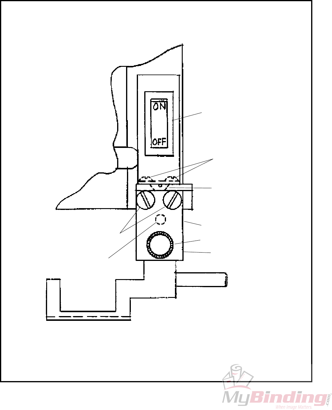
Hand Jog:
A hand jog is located at the rear of the machine. To
manually cycle the Bindery Mate: switch off power;
push in and rotate knob counter clockwise to go
through a normal stitch cycle, or clockwise for a
reverse cycle.
12
Master Out and SecondaryUnit In:
These outlets are only for use with the "Multiple
Stitch Accessories".
Saddle Stitching-Foot Switch Use
Only:
Switch off power. Swing up front guard assembly.
Turn the trip lever knob counter clockwise, and
move the work trip all the way back. Position the
table/saddle for saddle stitching. Swing down the
front guard assembly. Slightly loosen the two knobs
(counter clockwise) securing the front sliding guard
to the front guard. Allow the front sliding guard to
drop to the saddle position. Retighten the two knobs.
Plug the foot switch cord into foot switch outlet on
rear control panel (work trip is then automatically
passed). Switch power on. Load work from either
side and step on foot switch to cause a stitch.
CAUTION
AVOID DAMAGE TO YOUR
STITCHER BY FOLLOWING THESE
RULES:
1. Never operate your stitcher with wire
feeding unless you have work material
between the clinchers and benderbar.
2. Do not drive one stitch on top of
another.
Work Guides:
A. Side Guides: To adjust side guides pop-up the
pins at the end of each guide, loosen the screw
knob beneath the table, position guides as desired,
and retighten the screw knob.
B. Corner Stitch Guides-Table Use Only: Pop Up
the pins located in the table and the pins located
at the end of each side guide. Using your work
as a set up tool, position and secure the side
guides as indicated in figure 13. Switch off
power, swing upfront guard assembly, and move
the work trip all the way forward. Swing front
guard assembly back down and switch on power.
Push work into corner guided area of table until
depression of work trip causes a stitch.
Changing Work Thickness:
Changing work thichness will probably require a
change of the wire draw length used to make a
stitch. This is done by raising or lowering the face
plate. To change face plate position switch off
power; swing front guard assembly up to the second
detente position; loosen the faceplate screw
(Located directly above M2000 on the face plate),
move the position lever up for more wire or down
for less wire, retighten faceplate screw, and swing
down front guard.
Figure 13
(QF27F8)
13
Caution
MAKE ALL ADJUSTMENTS WITH
THE POWER OFF AND THE
STITCHING HEAD IN NEUTRAL
POSITION! (Fig. 14)
In neutral position, the wire grip assembly
(Index A) is stopped at the top of the slot
in the face plate.
Stitching Adjustments
Best stitching performance will be assured if all
adjustments are made so that you get the following
results:
1. Good Cut-Off
2. Uniform Wire Draw
3. Equal Leg Length
4. Proper Clincher Alignment
5. Sufficient Compression
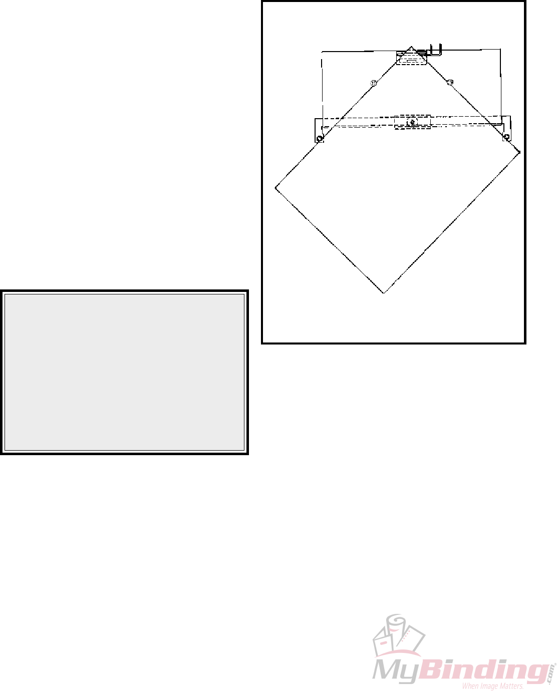
To Equalize Both Legs of Stitch
(Fig. 15)
1. Loosen the wire guide locking bolt (Index C).
2. Turn adjusting screw (Index D) clockwise to
shorten left leg of stitch; counter clockwise to
lenghten left leg.
3. Tap bracket (Index E) down before tightening
bolt (Index C).
General
Every Bindery Mates M2000 Head Stitcher has a
friction-type head which depends on smooth sliding
friction and proper timing to function correctly.
Preventative maintenance will go far to insure
trouble-free operation. Avoid production down time
by keeping your stitcher in top working condition at
all times.
Recommended Spare Parts
Like any equipment that has moving parts, certain
parts of your stitcher will be subjected to more
wear than others and require replacement. The
following listing includes all the parts required for
minimum maintenance and good operation of your
Bindery Mate.
PART NAME PART NO. QTY.
Wire Cutters CA9048 2
Grip CA9015D 1
Grip Spring CA168 1
Tension Roll Clip CA9124 2
Rotator CAA9038E 1
Clincher Points CA9083 2
Section 5
MAINTENANCE, TROUBLE
SHOOTING AND
ADJUSTMENTS
Figure 14
(CTTT2605T3 Scene 8)
Figure 15
(CTTT2605T3 Scene 9, 1)
E
C
D
A
14
2. Wrinkled crown.
M2000 Head Trouble Shooting
HERE'S HOW A PERFECT STITCH LOOKS
Should stitches appear in any form other than illustrated, one or more
kinds of mechanical trouble may have caused the malformation. The
possible causes and remedies are given for each kind of mechanical trouble
and are listed under each section. The remedies are indexed to the
Adjustments Section which gives more detailed information about your
stitcher, the mechanical trouble that may occur and suggested remedies.
Unless you recognize the correct cause, check each possible cause given.
TROUBLE POSSIBLE CAUSE REMEDY
A. Defective Stitches
See "To Equalize Both Legs of
Stitch" Page 13
"K" Page 24
"K" Page 24
Page 40
"P" Page 27
"I" Page 23
"R" Page 28
"K" Page 24
1. One or both legs buckled.
NOTE: Since buckled legs are
often concealed in the work and
may appear the same as a short
leg, always remove two or more
stitches to see which is
occurring.
1. Clincher is worn or improperly
aligned.
2. Insufficient compression.
3. Unequal leg length
1. Leg Lengths not adjusted
properly
2. Gripper is worn or dirty
3. Grip release slide is worn
4. Broken wire guide spring
(index 65H)
5. Excessive tension on wire
straightner
6. Worn Driver bar
7. Worn Tension Pawl or weak
tension pawl spring
8. Weak or broken grip spring
3. Length of one leg varies
"C,F" Page 20,22
"A,B" Page 20
See "To Equalize Both Legs of
Stitch" Page 13
"L" Page 25
"N" Page 26
"G" Page 22
4. Burred stitch leg.
5. Incorrect wire size.
6. Worn bender bar.
15
TROUBLE POSSIBLE CAUSE REMEDY
4. Corner of crown distorted or
fractured 1. Excessive compression
2. Broken driver bar end
3. Worn bender bar
4. Clincher improperly aligned
or worn
5. Incorrect wire size
"A,B" Page 20
"I" Page 23
"G" Page 22
"C,F" Page 20,22
"N" Page 26
5. Stitch crown not flat and legs
not bent into work 1. Insufficient compression "A,B" Page 20
6. One or both legs turn out 1. Clincher improperly aligned
2. Dull cutters
7. Flat piece of wire "O" Page 26,27
"P" Page 27
"O" Page 26,27
"O" page 26,27
8. Stitches come out in pieces "O" Page 26,27
"O" Page 26,27
"P" Page 27
"N" Page 26
"G,I" Page 22,23
9. Both stitcher legs are either
too long or too short See "Changing Work
Thichness" Page 12
"F" Page 22
"L" Page 25
1. Rotator is dirty
2. Improperly adjusted lower wire
straightener
3. Broken or worn rotator
4. Improperly aligned rotator
Face plate not adjusted properly
1. Improperly aligned rotator
2. Weak rotator operating spring
3. Improperly adjusted upper wire
straightener
4. Incorrect wire size
5. Wire jammed in bender bar
grooves
M2000 Head Trouble Shooting
16
M2000 Head Trouble Shooting
REMEDYPOSSIBLE CAUSETROUBLE
B. WIRE BUCKLES
1. Wire buckles above the grip
and below the tension pawl 1. Worn driver bar
2. Worn bender bar latch
3. Worn or broken bender bar
friction plug and/or spring
"I" Page 23
"J" Page 24
"H" Page 22
2. Wire Buckles above the wire
cutters and below the grip
1. Improperly aligned rotator
2. Worn or broken wire cutters
3. Burrs on rotator
4. Improperly adjusted lower
wire straightner
5. Worn or broken wire cutter
operating slide
6. Wire cutter slot in face plate
worn
"O" Page 26,27
"L" Page 25
"O" Page 26,27
"P" Page 27
"M" Page 26
"L" Page 25
C. GRIP
1. Grip does not close with
position lever up.
Face plate is too high Loosen face plate screw, turn
set screw (item 36H, page 40)
downward slightly in face plate
clip (item 35H, page 40),
retighten face plate screw.
Figure 16
(CTTT2605 Scene 10VA)
Figure 17
(CTTT2605 Scene10VB8)

17
Drive Trouble Shooting
POSSIBLE CAUSETROUBLE REMEDY
Power cord unplugged Plug in power cord
Contaminants on electrical
contacts of trip mechanism
Faulty electrical contact of trip
machanism. (Pressing the trip
should break the circuit between
the round trip locating rod, Item
25 page 35, and the hexagonal
paper trip rod, Item 24 page 35)
Faulty safety switch
Faulty motor (test using 90 vdc)
Faulty circuit board Replace circuit board
Replace motor
Faulty electrical connections Use electrical schematic page
42, 43 to check wiring
Remove trip machanism, clean,
repair, or replace contaminated
or damaged items
Turn trip lever knob counter
clockwise and move trip mecha-
nism from front to back a few
times
On/Off switch does not light
when switched on
Replace switch
Press in extended circuit
breaker
NOTE: If recently blown, wait
10 min. before pressing in
Circuit breaker is blown
Use electrical schematic page
42, 43 to check wiring
Faulty electrical connection
Stitcher drive does not operate
with work trip Safety switch is not being
depressed by front guard
Adjust front guard and/or safety
switch bracket
Foot switch is plugged in Unplug foot switch
Circuit breaker is blown Press in the extended citcuit
breaker. NOTE: If recently
blown, wait 10 min. before
pressing in
Faulty foot switch jack Repair or replace foot switch
jack
See foot switch schematic pages
42 and 43 for reference

18
TROUBLE POSSIBLE CAUSE REMEDY
Stitcher drive does not operate
when foot switch is depressed
Safety Switch is not being
depressed by front guard
Adjust front guard and/or safety
switch bracket
Circuit breaker is blown Press in the extended circuit
breaker. NOTE: If recently
blown, wait 10 min. before
pressing in.
Faulty foot switch (pressing foot
switch should break contacts of
switch inside Footswitch
assembly)
Replace footswitch
Faulty electrical connections Use electrical schematic page
42, 43 to check wiring
Faulty safety switch Replace switch
Faulty motor (test using 90 vdc) Replace motor
Faulty circuit board Replace circuit board
Stitcher keeps cycling, without
depressing footswitch or work
trip, until power is shut off
Faulty cam switch
Faulty electrical connections
replace switch
Use electrical schematic page
42, 43 to check wiring
Drive Trouble Shooting

19
NOTES
20
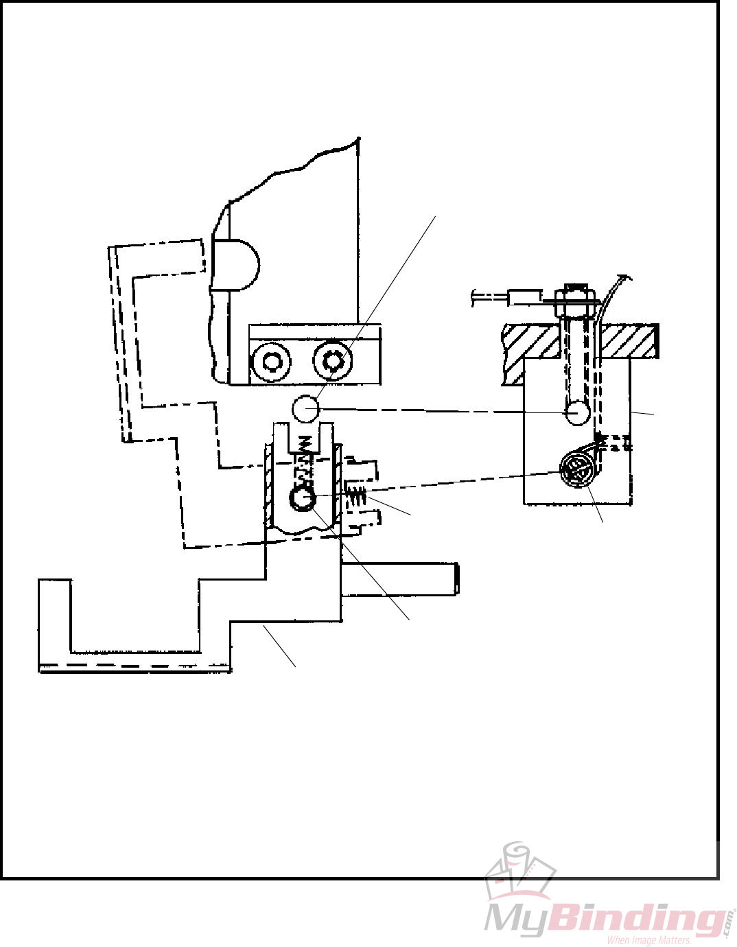
CAUTION
Turn Power OFF Before making Any
Adjustments
A. Insufficient or Excessive
Compression
Proper compression of work between the clincher
and the bender bars is necessary so that the stitch
penetrates the work material and clinches correctly.
To test for compression, drive several stitches into
sample work material. With proper compression,
stitches hold the work together firmly and the clinched
legs do not overlap. In the following instances,
either one or all of the conditions may exist: with
insufficient compression, stitch legs overlap, crown
of the stitch is fractured, and the work mutilated.
To change compression adjust the table/clincher
bracket.
B. Table/Clincher Bracket
Adjustment (Figure 18)
1. Remove wire from rotator, and turn the jog knob
clockwise until the bender bar is fully down.
2. Loosen the two screws (Index A) securing the
table/clincher bracket (Index B) to the stand
(Index C).
3. Move the table/clincher bracket up until the top
of the clincher assembly squarely touches the
bottom of the fully lowered bender bar. (Index
D)
4. Retighten the two screws.
C. Clincher (Figure 19)
The purpose of the clincher is to turn the legs of the
stitch back after they have penetrated the work
material.
With the Activated (moving) Type clincher, the stitch
legs must enter the clincher at the same time and
with equal spacing from each side. When the stitch
legs have penetrated the work material, the moving
clinchers are raised to bend the legs towards each
other and up flat against the work. The clincher
points must bend both legs of the stitch against the
work with the same force. Clincher points must
always move freely and not bind. Dirt, wire chips,
etc. will cause the points to bind.
The clincher points are in a retracted position in the
clincher box until the stitch legs penetrate the work
material. After the legs penetrate, the clincher points
move upward to give a neat, flat clinch against the
bottom surface of the work material. If the clincher
points remain in the up position, the legs of the next
stitch cannot penetrate the work material, causing
the stitch legs to buckle and/or the corners of the
crown to fracture. Examine the clincher points,
clincher slide for possible binding. Clean and oil.
If clincher points rise to high, they fracture the stitch
legs and/or mar the work. If the points do not rise
high enough, the legs will not clinch flat. Adjust the
height of the clincher points.
Figure 18
(QF27F9)
B
D
A
C
21
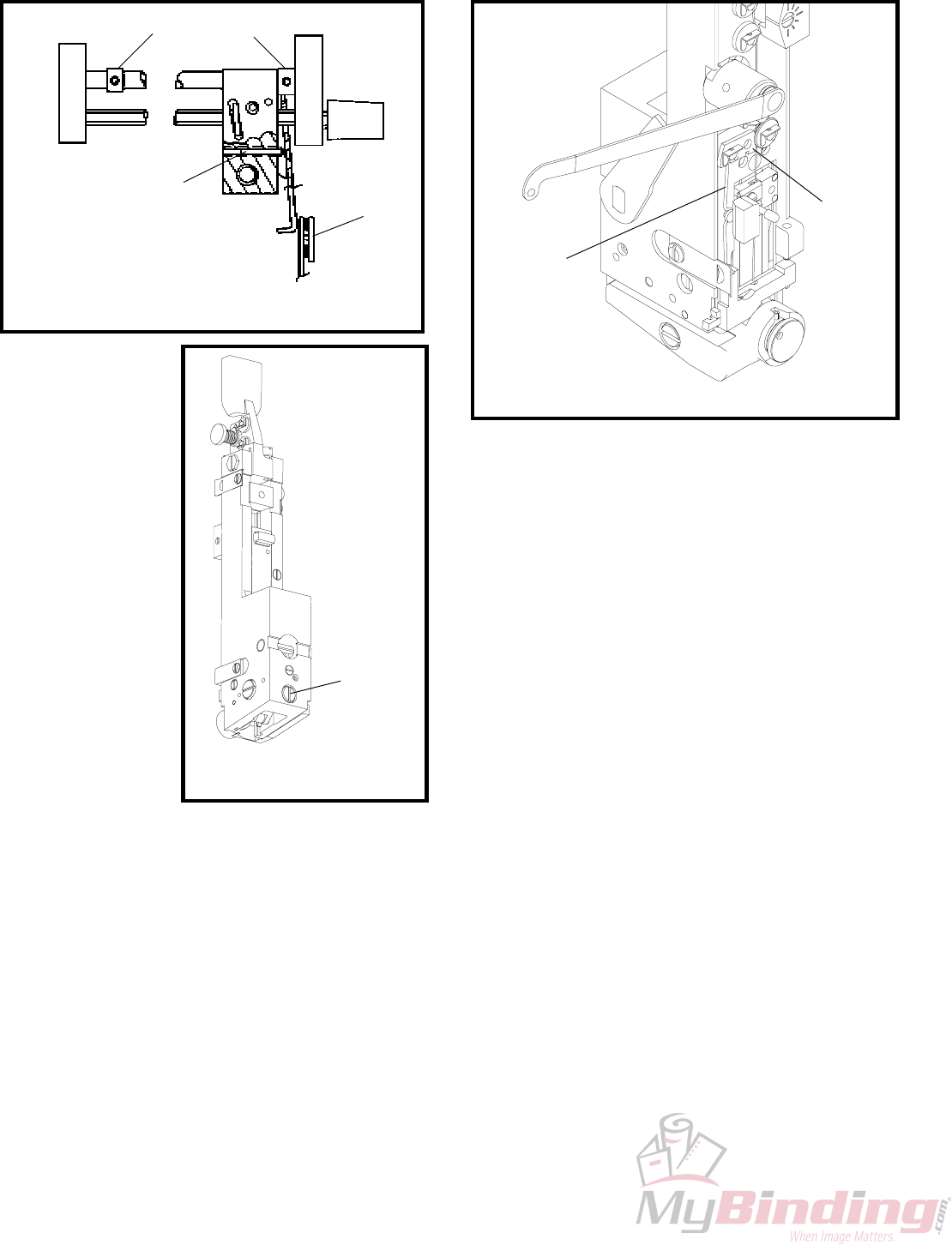
D. To Adjust Clincher Points
Height (Figure 20)
1. Turn off power and unplug power cord.
2. Remove wire coil, washer, compression spring
and stud.
3. Swing up front guard assembly to 1st detent
position.
4. Unscrew the four screws securing cover and
remove cover.
5. Unhook and remove the extension spring (Index
A).
6. Lift clincher operating lever (Index B) away
from clevis (Index C) and turn clevis clockwise
to lower the clinchers, counterclockwise to raise
the clinchers. Note: clinchers will raise or lower
.025" per 360 degree turn of clevis.
7. Reassemble unit.
If the clinchers points are broken, the stitch legs
will not clinch and/or be deformed. Reverse or
replace the clincher points.
E. To Reverse or Replace Clincher
Points (Figure 21)
1. Remove the two screws (Index A) securing the
clincher slide brace (Index B). Remove brace.
2. Move clincher slide away from clincher points
(Index C).
3. Raise the clincher points, and reverse or replace.
4. When reassembling, push the clincher points
down so that the top lip of the clincher slide
(Index D) will engage the center of the clincher
points. Note: Clincher slide must move freely
up and down after reassembly.
The proper alignment of the clincher under the
formers is one of the most critical adjustments on
the stitcher. Therefore, extreme care should be
taken to align the clincher so that both legs of the
stitch strike the clincher at the same time with equal
spacing from the outside edges of the grooves (See
Figure 19). Also, the clincher must be aligned with
the bender bar grooves of the head from front to
rear so that the legs enter the clincher at the widest
section of the clincher grooves.
Figure 19
(SK852F)
Figure 20
(QF27F10)
Figure 21
(QF27F11)
B
A
C
CD
A
B
Stitch
22
G. Bender Bar (Figure 24)
The bender bar bends the wire over the rotator and
forms it into an unclinched stitch. The legs of the
stitch are guided towards the work material by the
bender bar grooves. The legs of the unclinched
stitch should be perpendicular to the crown. When
the bender bar grooves become worn, the legs tend
to flare out (Figure 24) as they emerge from the
grooves. This causes the legs to strike the clincher
improperly. As a result, one or both legs will
crumple and a broken driver bar or a broken bender
bar can result. If the lower end of the bender bar
groove becomes chipped, it will not support the
wire and may cause the stitch to break at the crown.
Replace the bender bar assembly (See Section H or
Fig. 25). Other bender bar functions are related to
wire cutting (Section L), and driving (Section I).
H. Bender Bar Friction Plug
And/Or Spring (Fig. 25)
Two parts furnish pressure to coordinate movement
of driver bar and bender bar. If pressure is
insufficient, proper timing is not maintained for the
action of the grip. As a result, wire feeds backwards.
Replace the plug and/or spring.
To replace bender bar friction plug and/or bender
bar friction spring:
1. Remove bender bar assembly by following steps
1 through 23 of "Removing and Dismantling
M2000 Head", Pages 29 and 30.
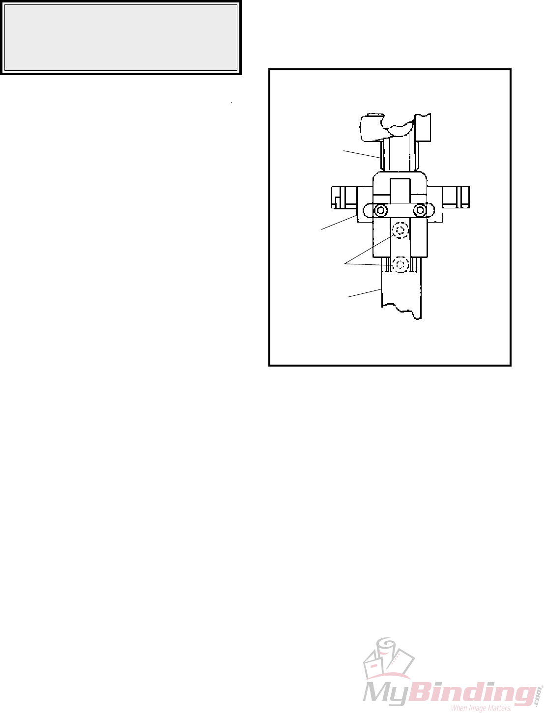
F. Head/Clincher Alignment
(Figures 22, 23)
To test alignment: Drive several stitches into a
section of material identical to that which is to be
stitched. The clinched legs should be identical and
aligned with each other. If the legs are not in
alignment, make the following adjustments:
1. With power off, press in and turn the jog knob
clockwise until the legs of the stitch (Index A,
Fig. 22) appear just below the bender bar (Index
B).
2. Loosen the four bolts (Index A, Fig. 23) securing
the base (Index B) to the stand (Index C).
3. Move the base until the legs of the stitch line
up with the clincher points (Index C, Fig. 22).
4. Tighten the four base mounting bolts.
Figure 22
(QF27F12)
Figure 23
(QF27F13)
Figure 24
(SK852I)
A
B
C
B
CA
23
2. Remove bender bar friction bushing (Index A).
Bender bar friction plug (Index C) and spring
(Index B) will be released forward from bender
bar assembly.
3. Replace plug and/or spring and reassemble.
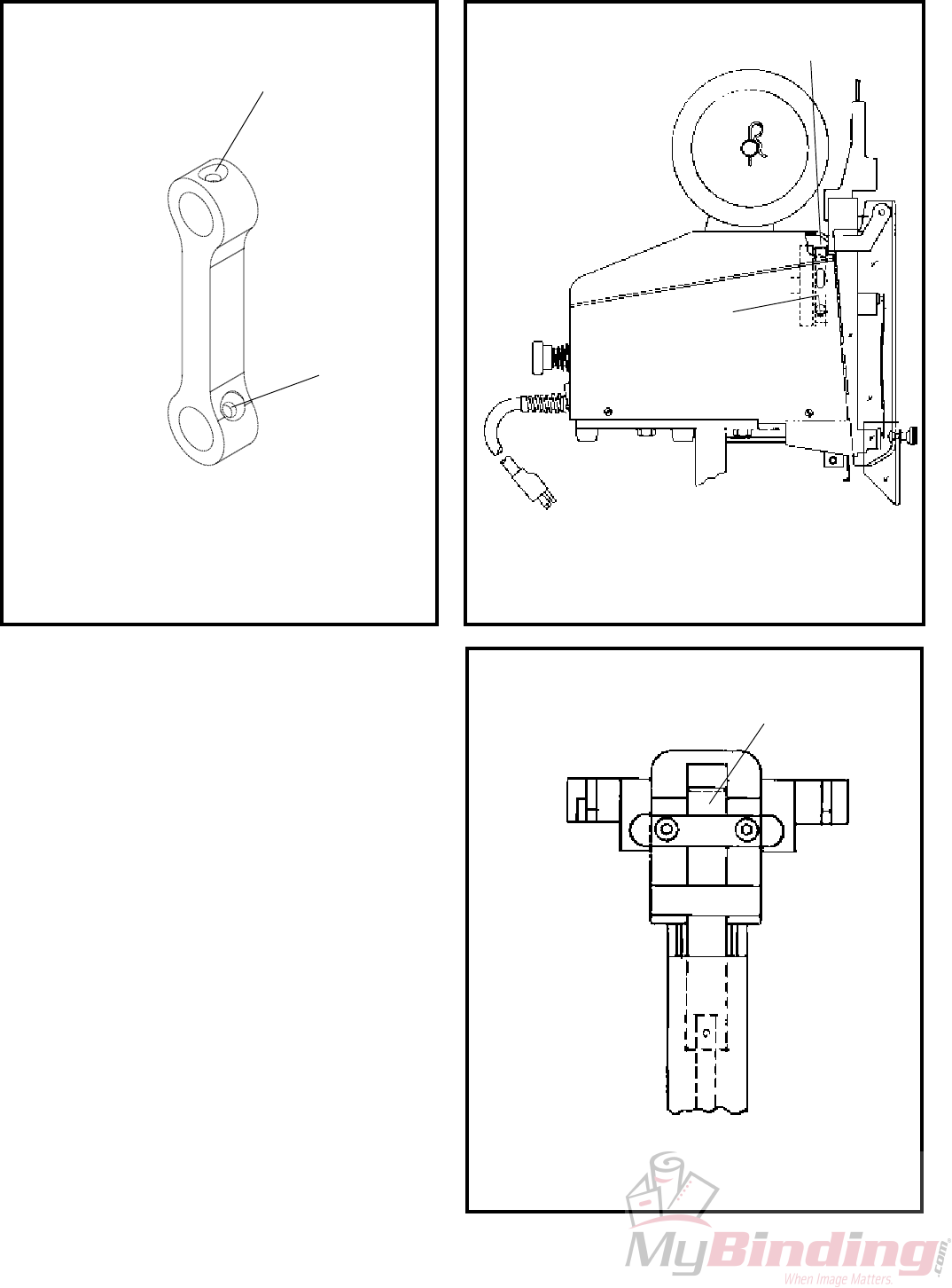
I. Driver Bar (Figure 26)
The driver bar (Index A) has several functions:
1. It imparts the downward thrust from the driving
slide assembly (Index B) to the bender bar
assembly (Index C).
2. It returns these parts to the neutral position on
the upstroke.
3. In conjunction with the grip release slide (Index
D), it controls the movement of the bender bar
latch (Index E) that opens and closes the grip
(Index F).
If the notches (Index G) at the top left side of the
driver bar become worn, the grip will not remain
open on the upstroke. As a result the wire feeds
backwards and buckles above the grip and below
the tension pawl. Worn notches can also cause
uneven wire draw. Replace the driver bar.
The notches shown on left side of driver bar play
an important part in function of bender bar assembly
therefore, corners should be free of dirt and notches
not marred.
The driver bar rides within the bender bar grooves
as part of the bender bar assembly. As this assembly
reaches the lower contact point of the cam in the
grip release slide, the bender bar latch is forced
inward, releasing the wire grip and permitting the
bender bar assembly to continue downward with the
end of the driver bar riding on top of the formed
stitch. When the bender bar is stopped against the
work material, the driver bar continues downward
to exert pressure on the crown of the stitch, driving
it through the work material.
If the end of the driver bar is chipped it allows the
legs of the stitch to back up into the broken area.
This causes the corner of the crown to fracture or
a "spike" section to protrude above the crown. A
chipped driver bar is usually the result of driving a
stitch on top of another stitch. A worn driver bar
often causes deformed stitches or fracturing at the
corners of the crown.
Figure 25
(CTTT2605 Scene 13)
Figure 26
(CTTT2605T3 Scene 10, CA9012M)
A
B
C
B
D
F
E
G
A
C
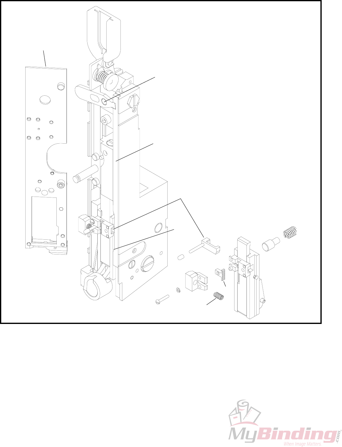
24
J. Bender Bar Latch
The bender bar latch opens and closes and is actuated
by the grip release slide and driver bar. If the
contact points of the latch become worn, timing of
the grip is erratic and uneven wire feed results. A
dirty latch will decrease pressure of the grip on the
wire. This causes wire slippage. Clean or replace
the latch.
K. Grip, Grip Release Slide and
Face Plate: (Figure 27)
The grip spring (Index A) exerts pressure on the
benderbar latch (Index B) to close the grip (Index
C) at the start of the down stroke. The grip release
slide (Index D) actuates the bender bar latch at
point X to open the grip after the correct amount of
wire has been fed to make a stitch. The serrated
teeth on the grip must be sharp or slippage will
occur, producing uneven wire draw.
Figure 27
(CTTT2605T3 Scene 11)
A
B
C
D
X
E
F
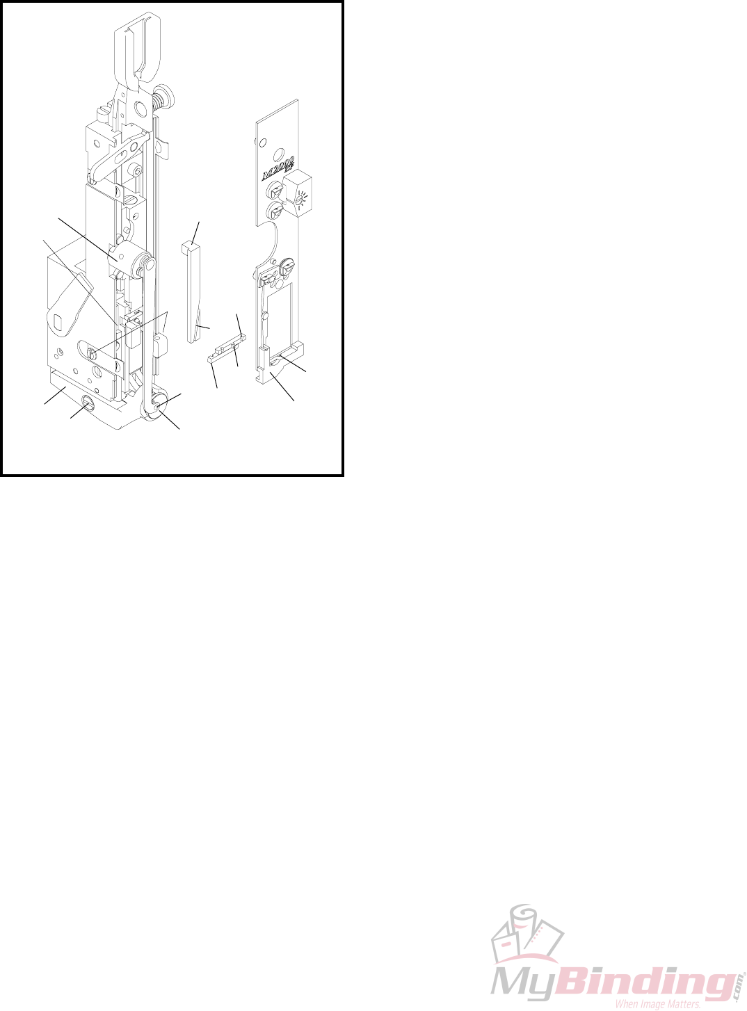
25
When the face plate (Index E) is adjusted (See
"Changing Work Thickness", page 12) a pivotal
action (at point F) changes the position of the grip
slide. When the face plate is raised, it moves the
grip release slide down. The gripper can then remain
closed longer, on the downstroke, feeding more wire
for the stitch. When the face plate is lowered, it
moves the grip release slide up. The gripper will
open sooner on the downstroke, feeding less wire
for the stitch.
If the grip is weak, uneven wire draw will result.
Replace the grip spring. If the contact points on the
grip release slide and/or the bender bar latch are
worn, wire adjustment will not remain accurate.
The face plate stops the bender bar assembly at the
top of its stroke and allows the bender bar latch to
close the grip. When the face plate is too high, too
much of the upstroke has been used before the bender
bar hits the face plate. In the remaining portion of
the upstroke, the driver bar cannot continue upward
enough to release the bender bar latch so that it can
close the grip.
L. Wire Cutters: (Figure 28)
The purpose of the wire cutters is to shear the wire
cleanly. There are two wire cutters, upper and
lower. The upper wire cutter (Index A) recieves
wire from the grip through the wire cutter lead-in-
hole (Index B). It also serves as the cut-off die.
The lower wire cutter (Index C) is the cutting knife.
If the cutter breaks, it will cover the lead-in hole.
This prevents the wire from feeding into the rotator.
If the cutting surfaces become worn, burrs will re-
sult on the end of the wire. This prevents the wire
from feeding into the rotator. As a result, the wire
buckles between the cutters and the wire grip. Re-
verse, interchange or replace the cutters.
To Reverse, Interchange or
Replace the Wire Cutters:
1. Loosen both face plate retaining clips (Index D)
at bottom of bonnet.
2. Spring the face plate out 1/8" while holding the
cutter clide in position (Index E).
3. Slide the cutters out to the left.
4. Reverse, interchange or replace the cutters.
NOTE
While installing the cutters, make sure that (1):
lip on upper cutter (Index F) fits into the recess
behind the face plate (Index G) and (2):that the
lip on the bottom cutter fits into the slot (Index
H) in the wire cutter operating slide (Index I).
The wire cutter operating slide actuates the lower
wire cutter. If the slide is worn or broken, the wire
cutter is not actuated. Replace the operating slide.
The slot in the lower part of the face plate contains
the wire cutter and maintains a close fit for wire
shearing. If this slot becomes oversized, the wire
will not be cut off. Replace face plate. To Replace
Face Plate (See Steps 1 through 10, Section M)
NOTE: (Figure 29)
The lug (Index C) in the faceplate must match
the slot (Index D) in the grip release adjusting
lever (Index E) or damage to the head may result.
Figure 28
(CTTT2605T3 Scene 12)
MI
A
H
E
D
KN
C
F
G
B
J
L
26
M. Wire Cutter Operating Slide
The wire cutter operating slide actuates the lower
wire cutter which acts as the cutting knife. If the
slide is worn or broken, the wire cutter is not
actuated. Replace the operating slide.
To Replace The Wire Cutter Operating Slide:
1. Cut the wire at the bracket and pull the loose
end out.
2. Remove the stitcher head assembly.
3. Lift end of spring (Index L, Figure 28) out of
rotator.
4. Swing the spring up to disengage it and lift out.
5. Slip the rotator operating cam (Index M, Figure
28) forward and off the stud.
6. Pull the rotator forward.
7. Loosen the two face plate retaining clips (Index
A, Figure 29) and rotate them downward.
8. Push two face plate retaining clips (Index F)
outward while lifting face plate up, or remove
retaining clips to release face plate.
9. Position grip spring housing (Index G) between
tension pawl spring retainer (Index H) and cutter
housing (Index I).
10. Remove face plate (Index B) by sliding face
plate to the left and lifting up.
11. Remove the cutter operating slide (Index I, Figure
28).
12. Insert a new cutter operating slide.
13. Reassemble
N. Proper Wire
The Bindery Mate is designed to use 25 gauge (.020"
diameter) 120,000 to 159,000 psi tensile strength
bookbinders wire.
If the wire used is larger than the bender bar grooves
were designed for, it will fracture at the stitch corners
and come out in pieces. Also, serious damage to
the stitcher may result. If the wire used is smaller
than the bender bar grooves were designed for, the
legs of the stitch do not fit snugly in the grooves and
may tend to buckle when they strike the work material
because they are not fully supported.
O. Rotator (Figure 28)
The rotator (Index J) (1) recieves the wire from the
cut-off die, (2) holds the wire while it is being cut,
then (3) turns it to a horizontal position, moves it
under the bender bar grooves and (4) supports the
wire while it is being formed into a "U-shaped"
stitch.
The wire lead-in-funnel of the rotator must be aligned
with the wire as it comes through the wire cutters.
If the rotator is improperly aligned, the wire hits the
rotator and buckles. Adjust upper two wire
straightners until wire slips past rotator. Burrs on
the rotator prevent the wire from entering the rotator.
This causes wire buckling. Remove the rotator and
polish the lead-in radius.
The magnets in the rotator hold the wire firmly in
the rotator. If a magnet is broken or chipped the
wire may fall out. To determine if the rotator has
the proper holding strength, remove the rotator and
insert a cut length of wire in the rotator. Hold
rotator between thumb and forefinger. Attempt to
jar wire loose by hitting heel on hand on top of
table or against other hand. With proper magnetic
holding force wire will remain in rotator. With
Figure 29
(CTTT2605T3 Scene 13)
E
C
D
I
H
G
F
B
A
27
insufficient holding force wire
will fall from rotator. Replace
the rotator.
The rotator holder and rotator
operating spring are responsible
for alignment of the wire beneath
the bender bar grooves. The
position of the rotator holder
determines how far the rotator
is pushed forward under the
bender bar by the rotator
operating spring (Index L). A
weak spring will not push the
rotator in far enough and with
this improper alignment the
bender bar will knock the wire
from the rotator or will shear
the wire into pieces. To secure
proper alignment, check the
position of the rotator operating
spring. Make any necessary
adjustment of the rotator holder
or replace the rotator operating
spring if weak.
The wire is fed into the rotator
and held for forming. If the
rotator is dirty, the wire is not
gripped securely enough and drops out. Remove
and clean the rotator. If the edges over which the
wire is formed are sharp, the corners of the stitch
crown will fracture. Remove the rotator and polish
the edges with a fine emery cloth.
To remove, Adjust or Replace the Rotator Holder:
1. Swing the rotator operating spring to the left.
2. Remove the rotator.
3. Loosen the rotator holder screw (Index N).
4. Adjust the rotator holder screw.
5. Re-assemble.
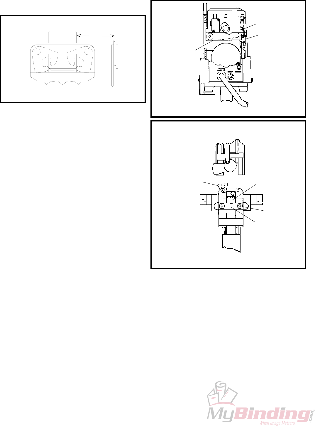
P. Wire Straighteners: (Figure 30)
All coils of stitching wire have a certain amount of
bundle curve. The purpose of a wire straightener
is to remove this curve. There is both an upper
wire straightener (Index A) and a lower wire
straightener (Index B) on all M2000 Model Stitchers.
See "Threading Wire and Adjusting Wire
Straighteners" page 6.
The upper wire straightener should feed wire parallel
to the faceplate. This insures that the wire will
properly enter the rotator and will be aligned with
the grooves in the bender bar. If the wire is not
parallel to the face plate the wire is sheared in the
rotator as the bender bar descends. Adjust the
upper wire straightener.
The lower wire straightener directs the wire straight
down so that it enters the rotator (Index C). If the
wire is not straight enough it hits the rotator and
buckles. Adjust the lower wire straightener so that
the wire points straight down as in figure 30.
Improper straightening of the wire can also cause
the stitch legs to buckle or turn out because they
strike the clincher improperly. Excessive tension
on the wire straightener prevents the grip (Index D)
from feeding the wire smoothly. This causes
variation in leg length.
NOTE:
Check the wire straighteners when changing the
coils to insure the accurate feeding of wire.
Figure 30
(CTTT2605T3 Scene 3, 4)
A
B
C
D
28
Q. Supporter
The supporter fur-
nishes the necessary
support to the inside
surface of the stitch
so that it does not
buckle as it is being
driven into the work
material. A lack of
(or insufficient) sup-
port will often cause
the stitch crown to
wrinkle or the legs
of the stitch to
buckle. Tighten the
supporter spring
bushing (Index A,
Figure 33) or re-
R. Tension Pawl: (Figure 32)
The tension pawl (Index A) and spring (Index B)
apply pressure on the wire to prevent back feed. If
the pawl becomes worn or the spring becomes weak,
the wire feeds backwards. Reverse or replace the
tension pawl and/or spring.
S. Work Trip: (Figure 31)
The amount of work trip lever overtravel can be
slightly increased or decreased by turning the
overtravel adjustment screw (Index A) located at
the rear of the trip lever guide.
1. Turn screw counterclockwise to increase trip
lever overtravel.
2. Turn screw clockwise to decrease trip lever
overtravel., NOTE: A small amount of trip lever
overtravel is always required or work trip will
not function properly.
NOTE:
Trip lever must NOT touch the clincher assembly
(Index B) when moved fully forward or the rear
table when moved fully back, or unit will not
work properly. If the trip lever touches clincher
decrease overtravel or loosen set screw in front
bumper (Index C) and reposition and secure
further back. If the lever touches rear table
loosen set screw in rear bumber (Index D) and
reposition and secure further forward.
DC
A
B
place the spring.
If the corners of the top surface of the supporter are
too sharp, or nicked, the corners of the stitch crown
will fracture. To inspect the supporter:
1. Turn the jog knob clockwise until the bender
bars touch the work material and the legs of the
stitch are about to leave the bender bar grooves.
At this point, the supporter should be touching
the underside of the crown. DO NOT TURN
THE MOTOR ON
2. Continue turning the jog knob until the stitch is
completely driven. Although the supporter is
gradually retracted by the driver, it should remain
under the crown of the stitch until the last instant
before the crown touches the work material.
Figure 31
Figure 32
(CTTT2605T3 Scene 15)
Figure 33
(CTTT2605T3 Scene 14)
A
B
A
29
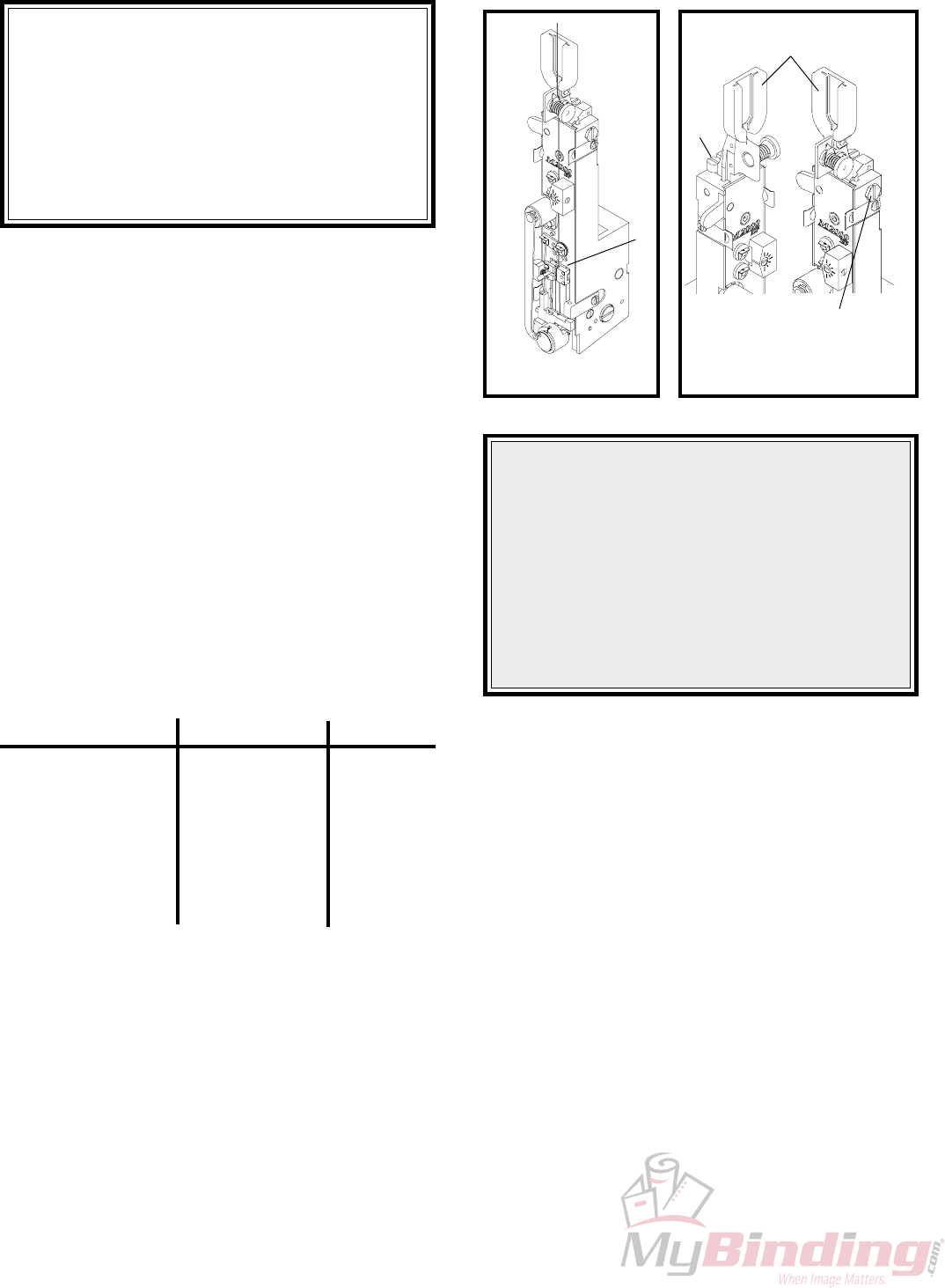
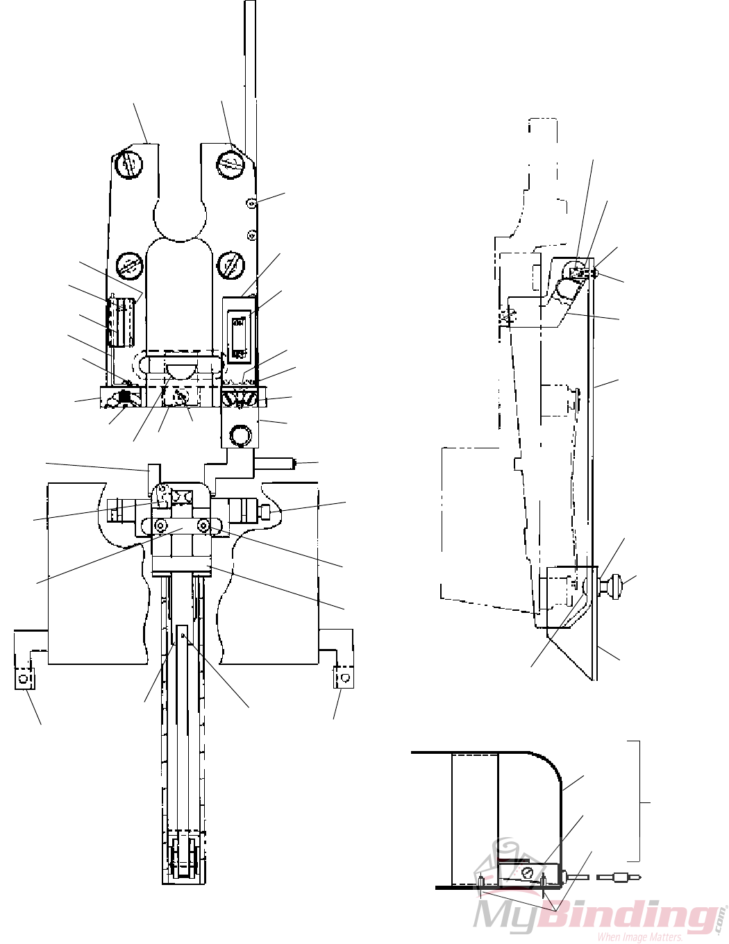
REMOVING AND DISMANTLING M2000 HEAD
CAUTION
As a precautionary measure-When removing
the head from any stitching machine make
SURE that the power to the machine has been
turned OFF or disconnected.
B
AC
D
(CTTT2605T3 Scene 17)
(CTTT2605T3 Scene 16) (CTTT2605T3 Scene 18)
Note: Before removing head use hand jog to make sure bender
bar is all the way up.
1. Cut wire at bracket
and secure.
2. Slip tension spring
from bracket.
3. Lift Bonnet Clamp
lever as shown.
4. Pull head froward
and off stitcher.
5. Loosen the top two
clip screws, and
remove clear guard
assembly.
6. Lift end of spring
out of rotator.
7. Swing spring up
to disengage.
Lift out.
8. Slip rotator operating cam
off.
9. Pull
rotator
forward.
CAUTION
The rotator operating cam can be
installed backwards. Be sure to
read fand follow the instructions
on page 30 before reassembling.
10. Remove
the upper
face plate
clips.
11. Remove the lower face plate clips.
12. Position grip
spring housing
between
tension pawl
spring retainer
and cutter
housing.
13. Remove the
face plate by
sliding face
plate to the left
and lifting up.
14. Remove the cutter
operating slide.
15. Remove the friction
plug and spring.
16. Remove rotator holder.
17. Remove
grip
release
slide.
(QF27F14)
30
REMOVING AND DISMANTLING M2000 HEAD
F
E
21. Slide tension spring bracket
and adjusting lever from top.
20. Remove
screw
22. Loosen face plate clamp screw and slide out face plate
locating block.
23. Slide the driving slide and bender
bar assemblies from the top. When
reassembling, hook bender bar to
driving slide before sliding into
place. This must be assembled as
a complete unit.
19. Remove
rotator
operating
cam
stud.
18. Remove
rotator
operating
cam stud
screw.
DO NOT
REMOVE
OR ADJUST
THESE TWO
SCREWS.
The screws
are factory set
to control the
supporter
lever location.
Caution
When reassembling,
make certain that pin
(Index A) is visible and is
aligned with slot (Index
B) of rotator operating
cam (Index C). If not
assembled in this way,
the bonnet casting will
crack or break on the
next cycle under power.
It is recommended that
the stitcher be cycled by
hand to test that proper
reassembly procedure
has been followed.
A
B
C
G
(CTTT2605T3 Scene 19)
(CTTT2605T3 Scene 21) (CTTT2605T3 Scene 20)
How to Install rotator
operating cam
31
DISMANTLING DRIVE
CAUTION
Disconnect power to the machine
before any disassembly.
A
C
B
NOTE: Head must be removed prior
to dismantling drive
1. Remove hairpin cotter
2. Remove spool retainer.
3. Remove coil
of wire.
4. Remove wire
spool washer.
5. Remove conical
spring.
6. Remove wire
spool stud.
7. Remove cover screws.
8. Remove cover.
9. Remove circuit board by gently
sqreezing here and then lift off
circuit board.
Note: If replacing circuit board, unplug
connector terminal from circuit board after
removing board.
Circuit board support
Circuit board
10. Remove circuit board
bracket.
14. Unplug motor terminals.
11. Unplug cam switch
terminals.
12. Remove extension spring.
13. Unscrew flat head bolts (4) and
remove motor.
(QF27F15) (QF27F16)
(QF27F17)
32
DISMANTLING DRIVE
D
15. Remove screws securing
ON/OFF switch bracket.
16. Remove two screws
from front glide
bracket
17. Hold front glide bracket in
place while removing the top
screw.
ON/OFF
SWITCH
BRACKET
TRIP LOCATING ROD
FRONT GLIDE BRACKET
PAPER TRIP ROD/KNOB
NOTE: Rear table must be removed prior
to trip mechanism disassemblly.
(QF27F18)
18. Hold the paper trip rod/knob in place
while gently pulling the front glide
bracket off of the trip locating rod.
33
DISMANTLING DRIVE
E
19. Gently lower trip mechanism until it is clear of the trip locating
rod. Do not yet pull away from rear glide bracket.
PAPER TRIP ROD
COMPRESSION
SPRING TORSION SPRING
REAR
GLIDE
BRACKET
TRIP LOCATING ROD
20. Rotate trip mechanism, with paper trip rod, clockwise to
unwrap the torsion spring. The trip mechanism with
paper rod can now be withdrawn from the rear glide bracket.
Reverse procedure for reassembly.
(QF27F19)
34
DISMANTLING DRIVE
Note: Remove saddle/table prior to
removing clincher slide
Note: After reassembly, clincher slide must move freely up and down
in clincher assembly.
21. Remove roll pin. 22. Lower clincher rocker lever.
23. Remove roll pin.
26. Slide out front clincher
rod with clincher slide.
25. Remove clincher brace.
24. Remove clincher brace
screws.
(QF27F20)
35
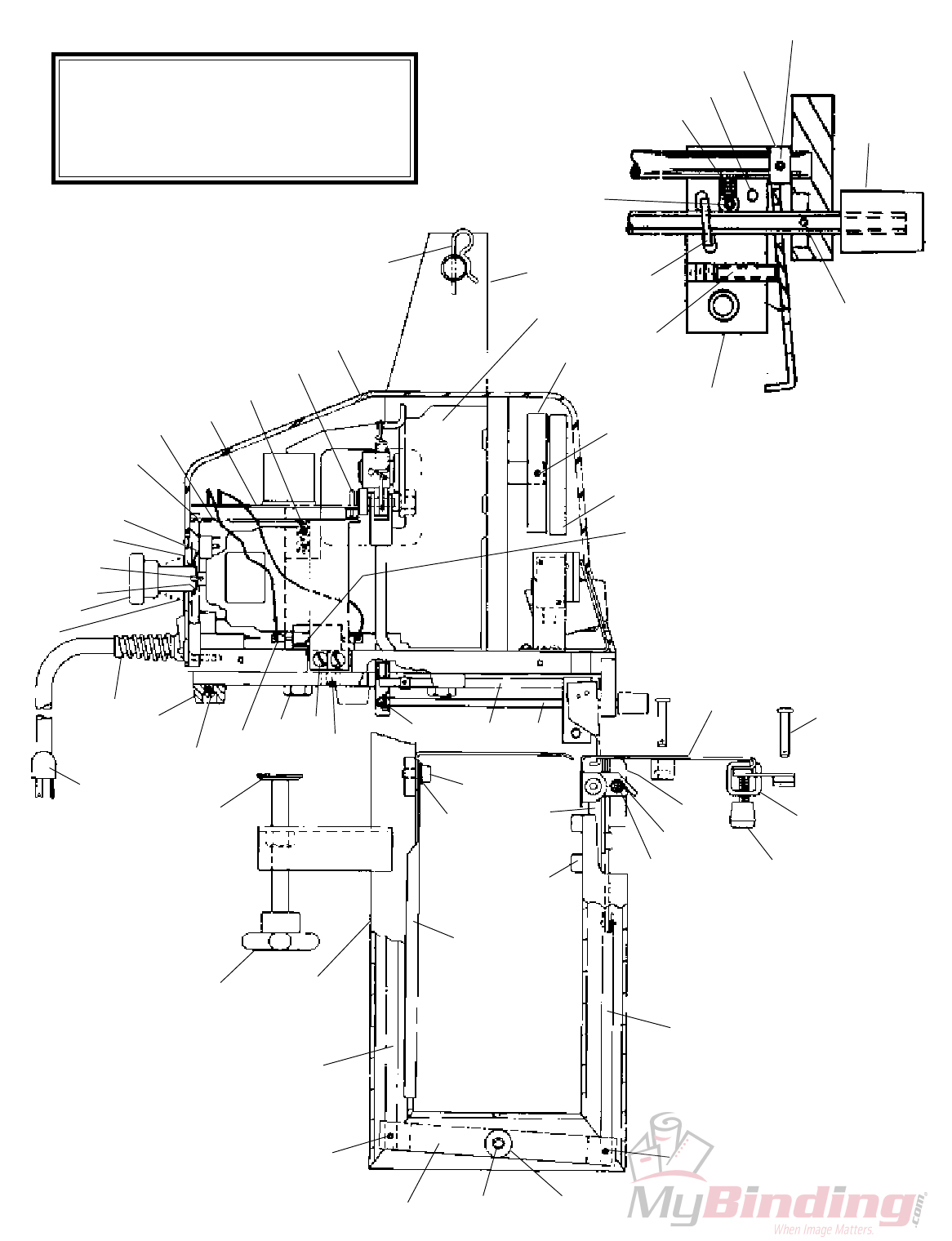
Section 6
PARTS LIST
1
2
3
4
5
55
54
53
52
51
50
49
48
47
46
45
44
43
42
41
40
124
38
37
36
35
34
33
20
32 31
28 127 29 2827 26 25 24
22
23
22
21
30
19 18
123
17
13
16 15 14
13
12
11
10
9
8
125
7
6
124
(QF27F21)
36
77
78
79
80
81
82
83
84
85
86
57
58
59
60
128
61
62
63
28
65
53
66
67
68 69
70
71
72
73
74
75
76
37
33
56
64
(QF27F22)
37
110
111
112
93
113
114
115
116
118
117
119
120
121
122
88 89
90
91
92
42
93
84
94
95
42
105
106
107
108
93
109
126
75
39
96
97
98
101
55
99
100
102
103
104
(QF27F23)

38
1 CK-138 SUPPORT 1 35
2 CG-115-A GEARMOTOR, 90 VDC (115 V A C ) 1 35
CG-115-B GEARMOTOR, 180 VDC (230 V A C ) 1 35
3 CKK-81-B CRANK ASSEMBLY, DRIVE SHAFT 1 35
CKK-81-A CRANK ASSEMBLY, DRIVE SHAFT 1 35
(FOR BINDERY MATE PRIOR TO SERIAL # 700)
4 D-23940-F PIN, ROLL, 125 x 88 Lg (CRANK) 1 35
5 CA-44-E HEAD OPERATING LINK 1 35
CA-44 HEAD OPERATING LINK 1 35
(FOR BINDERY MATE PRIOR TO SERIAL # 700)
6 CKK-154 SADDLE AND TABLE ASSEMBLY 1 35
7 CK-158 PIN, CLEVIS, COTTERLESS 4 35
8 CB-1253 KNOB 1 35
9 CK-150 BRACE, TABLE 2 35
10 CK-180-B SPRING, TORSION, TABLE 1 35
11 CK-152 BAR, PIVOT, TABLE BRACE 1 35
12 CK-148 ROD, CLINCHER, FRONT 1 35
13 D-37769-F PIN, ROLL, 125 x 500 2 35
14 CT-199 WASHER, 25 ID x 625 OD x 093 2 35
15 CB-835-Z PIN, ROLL, 250 X 1 00 SST 1 35
16 CK-145 LEVER, CLINCHER, ROCKER 1 35
17 CK-147 ROD, CLINCHER, REAR 1 35
18 CKK-137 STAND W/MT 1 35
19 CKK-193 CLAMP, ASSEMBLY 1 35
20 CBB-283-J CORD, POWER (115 V A C ) 1 35
CBB-283-S CORD, POWER (230 V A C ) 1 35
21 CK-151 BRACKET, TABLE AND CLINCHER 1 35
22 D-41440-F SCREW, 25-28 x 375 SOC HD CAP 4 35
23 CB-806 WASHER, FLAT, 250 2 35
24 CK-157 ROD, TRIP, PAPER 1 35
25 CK-136 ROD, LOCATING TRIP 1 35
26 CK-180-C SPRING, TORSION 1 35
27 CB-284-A PIN, DOWEL, 1875 X 75 1 35
28 CB-401 SCREW 8-32 X 375 RD HD 10 35,36
29 D-25947-F SCREW, 375-16 X 75 HEX HD 4 35
30 CK-168 DISC, CLAMP 1 35
31 CP-3-A BUMPER, POLYLASTOMER 4 35
32 CG-162-B BUSHING, STRAIN RELIEF 1 35
33 CK-180 SPRING, COMP , CONICAL 2 35,36
34 CKK-193-C KNOB ASSEMBLY 1 35
35 CB-837-L RING, RETAINING 1 35
36 CB-835-K2 PIN, ROLL, 093 x 437 LG 1 35
37 CA-114-A WASHER, FLAT, 625 ID x 1 5 OD x 04 2 35,36
38 CK-230 WASHER, 562 ID, 75 OD x 030 FLAT 1 37
39 CG-14-A SCREW, 4-40 x 50 RD HD 2 37
40 CK-182 BRACKET, CIRCUIT BOARD 1 35
41 CK-162 BOARD, CIRCUIT (115 V A C ) 1 35
CK-162-A BOARD, CIRCUIT (230 V A C ) 1 35
42 CB-206 SCREW, 8-32 x 375 FL HD 4 35,37
43 CK-183 SUPPORT, PC BOARD 4 35
44 CK-174 COVER 1 35
45 CK-176 COTTER, HAIRPIN 1 35
46 CK-170 GLIDE, LEVER, TRIP 1 35
47 CA-9077 SCREW, 6-32 UNC 2B x 500 SET 1 35
48 CK-156 WASHER, ECCENTRIC 1 35
49 CB-835-J2 PIN, ROLL, 093 X 562, SST 1 35
50 CA-5108-B SPRING, COMP 1 35
51 CK-175 PIN, TRIP LEVER 1 35
52 CB-434-A BUMPER, TRIP 2 35
53 D-31028-F SCREW, 6-32 X 25 SET 3 35,37
54 CK-193-B KNOB, TRIP LEVER 1 35
55 CB-835-T PIN, ROLL, 062 x 312 2 35,37
56 CA-45-B STUD, SPOOL WIRE 1 36
57 CA-139 SPOOL RETAINER 1 36
58 CB-56-R SCREW, 4-40 x 75 SOC HD CAP 2 36
59 CB-1070-A SCREW, 10-32 x 375 HEX HD 3 36
60 CK-149 CAM 1 36
61 CK-180-A SPRING, EXTENSION 1 36
62 D-30610-F PIN, ROLL, 187 x 625 LG 1 36
63 CK-146 CLEVIS 1 36
64 CK-153 TABLE, AUXILIARY 1 36
65 CK-166 BRACKET, GLIDE, REAR 1 36
66 CB-56-S SCREW, 5-40 x 50 SOC HD, CAP 2 36
MODEL 305
PARTS LIST
(See Pages 40 & 41 for M2000 HEAD Parts List.)
ITEM PART NO. DESCRIPTION QTY REF.
PAGE
67 CB-720 NUT, 6-32 HEX 2 36
68 CK-178 SCREW, 6-32 x 1 00 SET 1 36
69 CBB-283-K WIRE ASSEM , TRIGGER/FT JACK 1 36
70 CK-144 LEVER, CLINCHER OPERATING 1 36
71 CB-102-A NUT, 312-18 UNC 2B HEX 1 36
72 CK-181 WASHER, 390 ID x 625 OD x 062 7 36
73 CB-1421-G SHOULDER SCR , 375 DIA x 75 LG 1 36
74 CG-17 SPACER, LIMIT SWITCH 3 36
75 CG-15 SWITCH, LIMIT 2 36,37
76 CK-143 BRACKET, SWITCH, CAM 1 36
77 CG-190-A PHONE JACK, 097 DIA 2 36
78 CK-164-A WASHER, SWEDGED FIBRE, 097 DIA 2 36
79 CK-164-C WASHER, FLAT PHENOLIC, 097 DIA 2 36
80 CK-167 PANEL, CONTROL, REAR (115 V A C ) 1 36
CK-167-B PANEL, CONTROL, REAR (230 V A C ) 1 36
81 CG-190-B PHONE JACK, 141 DIA 1 36
82 CK-164 WASHER, SWEDGED FIBRE, 141 DIA 1 36
83 CK-164-B WASHER, FLAT PHENOLIC, 141 DIA 1 36
84 CB-206-B SCREW, 8-32 x 625 FL HD 4 36,37
85 CK-163 CIRCUIT BRKR ASSEM (115 V A C ) 1 36
CK-163-A CIRCUIT BRKR ASSEM (230 V A C ) 1 36
86 CB-55-F SCREW, 4-40 x 375 FL HD 3 36
88 CK-135 PLATE, MOTOR, MTG 1 37
89 CB-587 SCREW, 250-20 x 75 FL HD 4 37
90 CB-56-P SCREW, 5-40 x 75 SOC HD 8 37
91 CK-172 BRACKET, SWITCH, ON-OFF 1 37
92 CB-2 8 5-P2 SWITCH, ON-OFF ILLUM (115 V A C ) 1 37
CB-2 8 5-S2 SWITCH, ON-OFF ILLUM (230 V A C ) 1 37
93 CB-287-B SCREW, 6-32 X 312 RD HD 8 37
94 CK-165 BRACKET, GLIDE, FRONT 1 37
95 CB-835-Y PIN, 250 x 1 50 SST 1 37
96 CB-1421-E SCREW, SHOULDER 2 37
97 CB-561 SCREW, 10-32 x 50 SOC HD CAP 2 37
98 CTT-9086 CLINCHER PLATE ASSEMBLY 1 37
99 CA-2095-J CLINCHER SLIDE 1 37
100 CK-160 GUIDE, PAPER L H 1 37
101 CK-161 GUIDE, PAPER R H 1 37
102 CA-9085-H BRACE, SLIDE, CLINCHER 1 37
103 CA-9083 CLINCHER POINTS 2 37
104 CK-155 TRIP, LEVER, PAPER 1 37
105 CK-179 PLATE, RETAINER 1 37
106 CTT-9002 BONNET CLAMP ASSEMBLY 1 37
107 CB-619 SCREW, 250-20 x 1 FL HD 2 37
108 CK-134 BASE 1 37
109 CK-190 BRACKET, SW , SAFETY 1 37
110 CK-192 PIN, PIVOT, BLOCK 2 37
111 CK-191 BLOCK, PIVOT, GUARD 1 37
112 CF-1989 WASHER, #6 FLAT 2 37
113 CK-186 SPRING/SUPPORT, GUARD 1 37
114 CK-187 GUARD, FRONT 1 37
115 CB-1262 WASHER, #10, FLAT 2 37
116 CA-9067-B NUT, ECCENTRIC, WIRE STR 2 37
117 CK-189 BOLT, 10-24 x 50 CARRIAGE 2 37
118 CK-188 GUARD, SLIDING, FRONT 1 37
119 CB-2095-D GUARD, FOOTSWITCH 1 37
120 CB-502-M FOOT SWITCH 1 37
121 CK-177 SCREW, NO 4 THR'D FORMING 2 37
122 CBB-502-M FOOTSWITCH ASSEMBLY 1 37
123 CK-196 GUIDE, PAPER 1 35
124 CG-14 SCREW, 4-40 X 250 RD HD 4 35
125 CK-198 BRACKET, PAPER, GUIDE 1 35
126 CK-229 GUIDE, GUARD 2 37
127 CKK-234 RESISTOR ASSEMBLY 1 35
128 D-38063-F PIN, ROLL 125 x 625 1 35
ITEM PART NO. DESCRIPTION QTY REF.
PAGE

39
NOTES

40
1H
70H
2H
11H
9H
10H
8H3H 4H
5H 6H
7H
13H
14H
33H 32H
34H
37H
40H
38H
12H
37H
(39H)
67H
65H
69H
68H
67H
66H
64H
34H
49H
37H 31H
30H
47H
46H
50H
51H
52H
(9H)
(10H)
62H
53H
39H
36H 37H
41H
35H
44H
43H
15H
45H
42H
48H
57H
58H
54H
55H
56H
60H
63H
59H
61H
21H
22H
23H
24H
17H
16H
19H
20H
18H
25H
26H
27H
28H
29H
34H
(CTTT2605T3 Manual)
Note: See Section
F page 30 before
assembling.

41
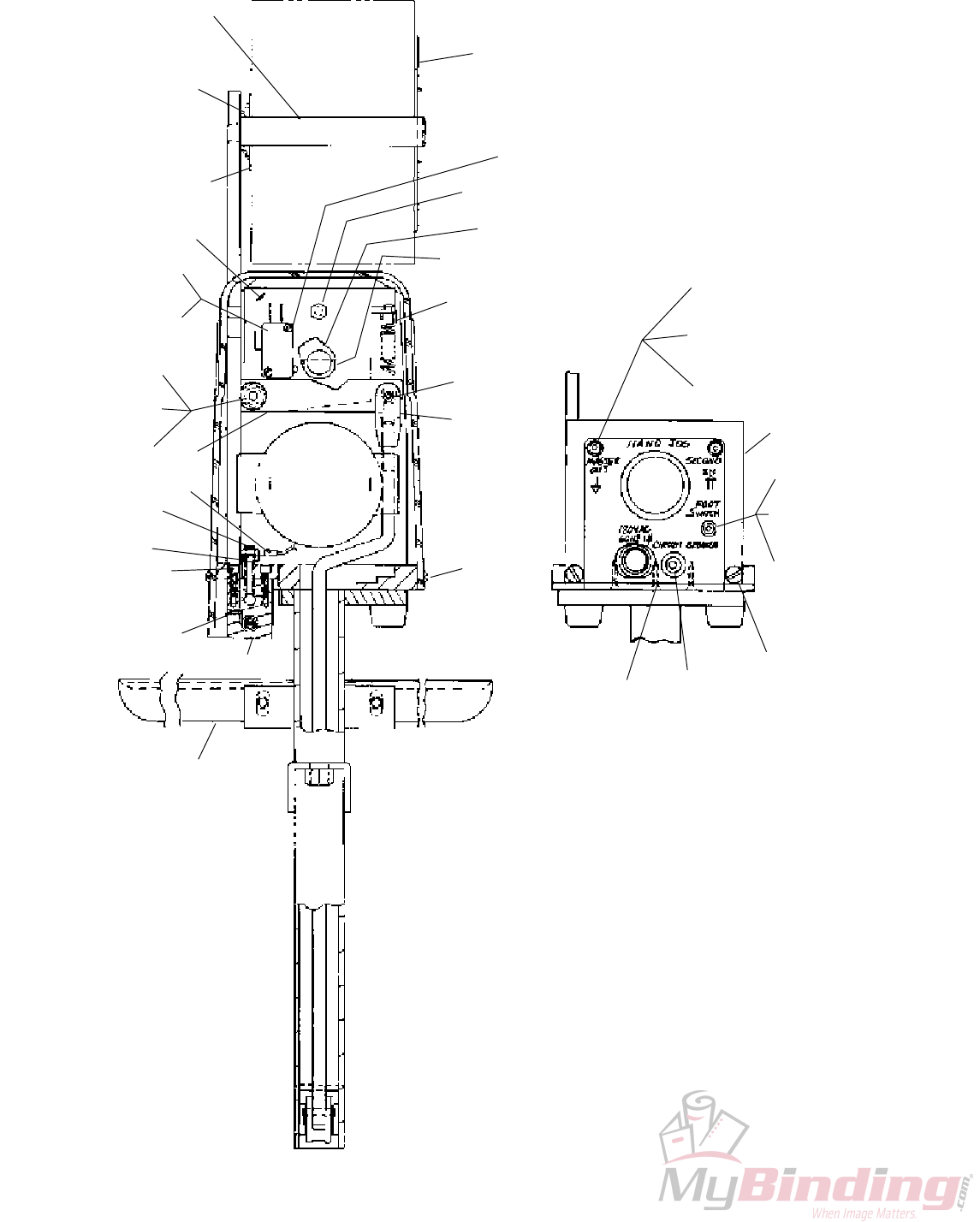
M2000 HEAD
PARTS LIST
The following parts listing (from index numbers 1H through 70H) is for the
Bindery Mate's M2000 Head, CTTT-2605-T3.
1H CAAA9074A2 WIRE GUIDE BRACKET ASSEMBLY 1
NOTE The above Wire Guide Bracket Assembly includes the
following items through item 11H
1H CAA9074A2 WIRE GUIDE BRACKET SUB-ASSEMBLY 1
2H CA9146A ECCENTRIC SCREW 1
3H CA9068 ECCENTRIC FRICTION BUSHING 1
4H CA9065 ECCENTRIC ROLL 1
5H CA9070 ECCENTRIC POINTER 1
6H CA9069 ECCENTRIC SPRING 1
7H CA9067 ECCENTRIC NUT 1
8H D31028F SET SCREW 1
9H CA9103C WIRE STRAIGHTENER ROLL 2
10H CA9124 TENSION ROLL CLIP 2
11H CA9076 WIRE GUIDE SPRING BRKT ADJ SCREW 1
12H CB77 FACE PLATE LOCATING BLOCK SCREW 1
13H CT2606 FACE PLATE LOCATING CLAMP 1
14H CT2607 FACE PLATE LOCATING BLOCK 1
15H CAA2623C DRIVING SLIDE ASSEMBLY 1
NOTE The above assembly includes the following parts
CA2623B DRIVING SLIDE (ONLY)
CA2007A DRIVING SLIDE SPRING PLUNGER
CA9006A DRIVING SLIDE SPRING
D37327F DRIVING SLIDE SPRING PIN
CA9028 DRIVING SLIDE ROTATOR OPERATING PIN
16H CAAA9013Z2 BENDER BAR ASS'Y COMPLETE 1
1/2" CROWN #25 TO #30 RD WIRE
NOTE The above Bender Bar Assembly includes the following items
through item 29H
16H CAA9013U BENDER BAR SUB ASSEMBLY
1/2" CROWN #25 TO #30 RD WIRE
17H CAA9026 SUPPORTER ASSEMBLY 1/2" CROWN 1
18H CA9029 SUPPORTER PIVOT PIN 1
19H CAA9014J BENDER BAR LATCH ASSEMBLY 1
20H CA173 PLASTIC CAP 1
21H CA9012M DRIVER BAR ASSEMBLY 1/2" CROWN 1
22H CA9112A BENDER BAR FRICTION PLUG 1
23H CA9113A BENDER BAR FRICTION PLUG SPRING 1
24H CA9115 BENDER BAR FRICTION BUSHING 1
25H CA9015D GRIP 1
26H CA168 GRIP SPRING 1
27H CT413A SPRING HOUSING 1
28H CB371K LOCKWASHER 1
29H CA9024A GRIP RETAINING CLIP SCREW 1
30H CTT2604N BONNET CASTING SUB ASSEMBLY 1
31H CA9127 ROTATOR OPERATING CAM STUD 1
32H CA9058 ROTATOR OPERATINGCAM STUD SCREW 1
33H CA9075 WIRE GUIDE BRACKET SCREW 1
34H CA9056C FACE PLATE RETAINING CLIP 3
35H CA9056D FACE PLATE RETAINING CLIP 1
36H CK213 SCREW, 4-40 X 500 SOC HD SET 1
37H CA2081 FACE PLATE RETAINING CLIP SCREW 4
38H CT9109 BONNET ALIGNMENT SCREW 1
39H CA9032C SUPPORTER SPRING 1
40H CA9037 SUPPORTER SPRING BUSHING 1
41H CA9081 SUPPORTER GUIDE PLATE SCREW 2
42H CA9030 SUPPORTER GUIDE PLATE 2
43H CAA9036B SUPPORTER SPRING LEVER 1
44H CA9034 SUPPORTER SPRING LEVER SCREW 1
45H CA9049A WIRE CUTTER OPERATING SLIDE 1/2" CR 1
46H CA9050A WIRE CUTTER OP SLIDE FRICTION 1
PLUG
47H CA9051A WIRE CUTTER OP SLIDE FRICTION 1
PLUG SPRING
48H CA9022J GRIP RELEASE SLIDE 1/2" CROWN 1
49H CA9025F FACE PLATE ADJUSTING LEVER 1
50H CAAA2132W FACE PLATE ASSY 1/2" CROWN #22 TO 1
#30 RD WIRE
NOTE The above Face Plate Assembly includes the following items
through item 56H
(9H) CA9103C WIRE STRAIGHTENER ROLL 2
(10H)CA9124 TENSION ROLL CLIP 4
50H CAA2132W FACE PLATE SUB ASSY 1/2" CROWN 1
#22 TO #30 RD WIRE
51H CA9065A WIRE STRAIGHTENER ECCENTRIC ROLL 1
52H CA9066A WIRE STRAIGHTENER ECCENTRIC 1
53H CA172 ECCENTRIC FRICTION LOCKING SCREW 1
54H CA9098 TENSION PAWL 1
55H CA9103A CHECK PAWL ROLLER 1
56H CA9134 TENSION PAWL SPRING 1
57H CA9048 WIRE CUTTER 2
58H CA9043M ROTATOR HOLDER #25 TO #30 RD WIRE 1
59H CB75B KEY, WOODRUFF 1
60H CA9044A ROTATOR HOLDER SCREW 1
61H CAA9038E ROTATOR ASSEMBLY COMPLETE, 1/2" CR 1
62H CA9163C ROTATOR OPERATING CAM 1
63H CAA9046D ROTATOR OPERATING SPRING ASSEMBLY 1
64H CTT9003D BONNET CLAMP ECCENTRIC 1
65H CTTT2133C2 WIRE GUIDE ASSEMBLY 1
NOTE The above Wire Guide Assembly includes the following items
through item 70H
(39H)CA9032C SUPPORTER SPRING 1
65H CTT2133C2 WIRE GUIDE SUB-ASSEMBLY 1
66H CB651E SCREW 1
67H CA9651 WASHER 2
68H CA9652 FELT WASHER, THICK 1
69H CA9653 FELT WASHER, THIN 1
70H CB860B NUT 1
ITEM PART NO. DESCRIPTION QTY ITEM PART NO. DESCRIPTION QTY
42
Section 7
ELECTRICAL
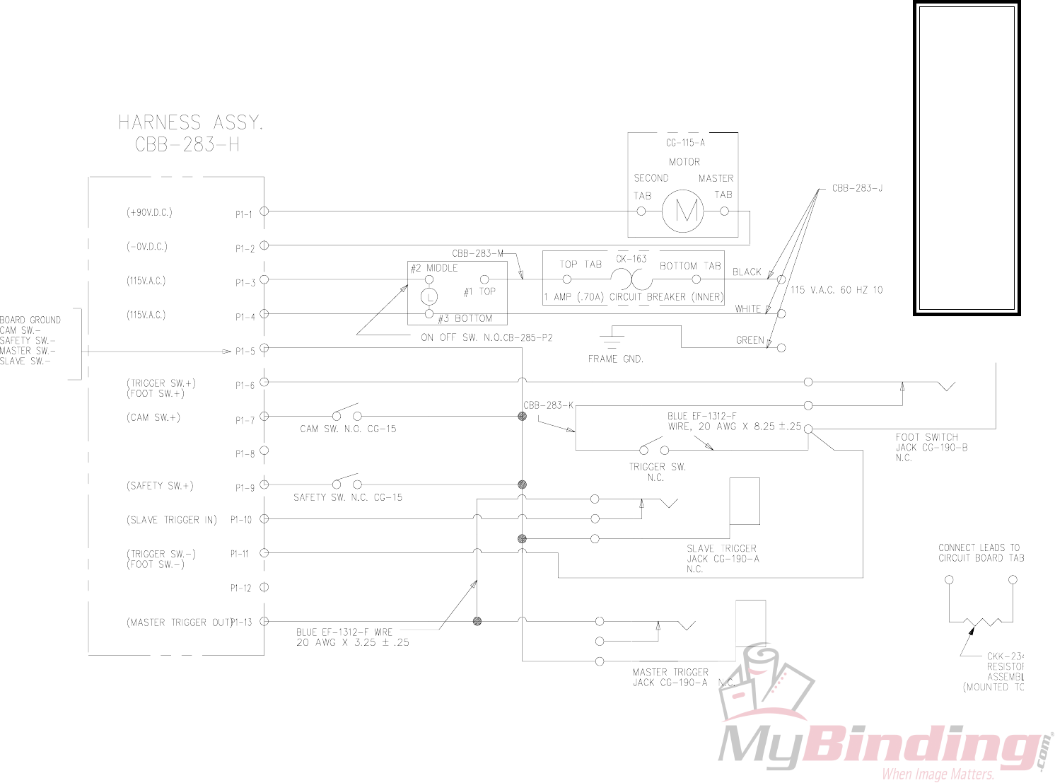
ELECTRICAL SCHEMATIC 115 V.A.C.
(SK828)
43
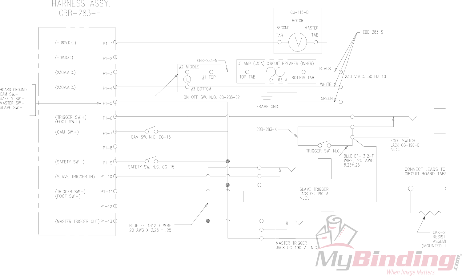
ELECTRICAL SCHEMATIC 230 V.A.C.
(SK828B)

BINDERY MATE
WHEN ORDERING PARTS, PLEASE STATE: QUANTITY REQUIRED, PART
NUMBER, PART NAME, WIRE SIZE AND CROWN WIDTH OF YOUR STITCHER.
USA:
3911 S. Memorial Dr. Racine, WI 53403
1-800-345-6641 1-262-589-5421
Fax: 1-262-598-5426
www.ispstitching.com
FORM QF27D 7-9-02
ISP
Stitching & Bindery Products
A Division Of Samuel Strapping Systems
