MyBinding Mbm Ep Cutter Error Codes User Manual
2013-06-04
User Manual: MyBinding Mbm-Ep-Cutter-Error-Codes
Open the PDF directly: View PDF ![]() .
.
Page Count: 3


Error codes for EP-machines.
Error code Er-10:
Backgauge motor is defetive or moves too strong.
Please check, if the backgauge is on it’s endposition and has jammed. The tooth belt
of the drive system should be moved easily. When the back gauge has not jammed,
please check the function of the potentiometer 5221 495 inside the handwheel for
correct adjustment by the enclosed diagnostic routine. Also check the capacitor 9002
635 for correct function. If potentiometer is defective or not correctly adjusted, the
display will also show Er-10.
Error code Er-15:
Please check the wiring 4850 552 going from the PCB A4 to the Counter PCB 5221
504 ( see enclosed drawing of the parts list ) for broken wire or connection. Also
check Counter PCB for correct soldering.
Error code Er-04:
Please check the function and value of the potentiometer (see diagnostic routine).
Error code Er-14:
Please check the postion of the backgauge. When the backgauge is on the rear,
please adjust the limit switch rear of the back gauge a little bit forwards and calibrate
the machine. When it happens in the middle, please check the function of the limit
switch. If limit switch is ok, please replace PCB A4.
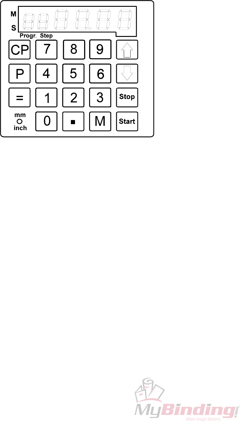
Diagnostic routine EP-Version
1. Turn main switch Q1 off until the display disappears.
2. Press and hold switch “mm/inch”. Turn on the main switch Q1 and release switch
“mm/inch”. The display shows: 88 88.88.
3. Press button “9”. The display shows “rb 19”. The actual version of the display is shown.
4. Press button “9”. The display shows “rt 19”. The actual version of the PCB A4 is shown.
5. Press button “9”. The display shows “Ad 40”.
Value of potentiometer A5 in normal position 38–42 in segment 5+6. Best adjustment is 40.
Potentiometer turned to the left: value 0-10. Best adjustment is 0.
6. Press button “9”. The display shows “Cr XX”
Diagnostic of the button can be done in following sequence:
0 = Cr.10 8 = Cr 08 P = Cr 18
1 = Cr.01 9 = Cr 09 = = Cr 19
2 = Cr.02 . = Cr 20 CP = Cr 17
3 = Cr.03 M = Cr 11 mm/inch = Cr 16
4 = Cr.04 Ï = Cr 13
5 = Cr.05 Ð = Cr 12
6 =
Cr.06 Stop = Cr 14
7 = Cr.07 Start = Cr 15
7. Press button “9”. The display shows “St ON 00”:
Segment 1+2 : limit switch
Segment 3+4 : status of limit switch (On – OFF), when pressed by hand.
Segment 5+6 : number of limit switch, when actuated (see wiring diagram).
8. Press button “9”. The diagnostic routine is finished. The display shows “CHEC” and then
“E 55” or “l lll”. Press “Start” and the backgauge moves to its set position.
Jan.03/Ro.
