MyBinding Plockmatic Ftr2000 Service Manual User
2013-06-04
User Manual: MyBinding Plockmatic-Ftr2000-Service-Manual
Open the PDF directly: View PDF ![]() .
.
Page Count: 77


TRIMMER FTR 2000
SERVICE MANUAL
This manual applies to the FTR 2000 both in left and right version.
Within this document, all references to right version also apply to the left version
unless specially mentioned.
The difference is basically that the two models are mirrored. All pictures within this manual are of
the right version.
Due to the mirroring, typical Front and Rear designations which normally is viewed from the opera-
tor location has been replaced by Left and Right. Left and Right is viewed from the paper direction.
Clearication:
Left = Rear for right version & Front for left version
Right = Front for right & Rear for left
20 September 2006, Rev 0.01
Subject to change

Page intentionally blank

III
20 September 2006, Rev 0.01
TABLE OF CONTENTS
1 INSTALLATION PROCEDURE
1.1 INSTALLATION PROCEDURE .........................................................FTR-1-1
2 PREVENTIVE MAINTENANCE SCHEDULE
2.1 PREVENTIVE MAINTENANCE SCHEDULE ...................................FTR-2-1
3. REPLACEMENT AND ADJUSTMENT
3.1 COVERS ...........................................................................................FTR-3-1
3.1.1 FRONT AND REAR COVER ...................................................FTR-3-1
3.1.2 TOP COVER ...........................................................................FTR-3-2
3.1.3 BLOWER MOTOR M5 / M6 .....................................................FTR-3-3
3.1.4 INFEED COVER ......................................................................FTR-3-4
3.1.5 LOCKING BRACKET ..............................................................FTR-3-5
3.1.6 UPPER OUTFEED COVER ....................................................FTR-3-6
3.1.7 INTERLOCK SWITCH S9 &S10 ..............................................FTR-3-7
3.1.8 LOWER OUTFEED COVER ...................................................FTR-3-8
3.1.9 PROTECTION COVER ...........................................................FTR-3-9
3.2 AREA C ........................................................................................... FTR-3-11
3.2.1 INFEED SENSOR Q13 ......................................................... FTR-3-11
3.2.2 CONTROL SWITCH S2 ........................................................FTR-3-12
3.2.3 CONTROL SWITCH S3 ........................................................FTR-3-13
3.2.4 TRANSPORT MOTOR M1 ....................................................FTR-3-14
3.2.5 TRANSPORT BELT SENSOR Q4 .........................................FTR-3-15
3.2.6 TRIM KNIFE MOTOR M2 ......................................................FTR-3-16
3.2.7 TRIM KNIFE HOME POSTITON SENSOR Q5 .....................FTR-3-17
3.2.8 TRIM KNIFE ..........................................................................FTR-3-18
3.2.9 PAPER PATH & OUTFEED SENSOR Q6 .............................FTR-3-22
3.2.10 STOP GATE CARRIAGE .......................................................FTR-3-23
3.2.11 STOP GATE MOTOR M3 & SENSOR Q7 .............................FTR-3-24
3.2.12 LENGTH ADJUSTMENT MOTOR M4 & SENSOR Q12 .......FTR-3-25
3.2.13 LENGTH ADJUSTMENT HOME POSITION SWITCH S11 ...FTR-3-26
3.2.14 LOWER OUTFEED BELTS ...................................................FTR-3-27
3.2.15 UPPER OUTFEED BELTS ....................................................FTR-3-28
3.2.16 TRIM BIN FULL SENSOR Q8 ...............................................FTR-3-29
3.2.17 TRANSMISSION CHAIN .......................................................FTR-3-30
3.2.18 KNIFE SUPPORT CHAIN .....................................................FTR-3-31
3.2.19 KNIFE CHAIN ........................................................................FTR-3-32
3.2.20 INFEED BELTS .....................................................................FTR-3-33
3.3 PCB ................................................................................................FTR-3-35
3.3.1 MD6DC PCB ”A” ....................................................................FTR-3-35
4. TROUBLESHOOTING
4.1 FAULT CODE DESCRIPTIONS ........................................................FTR-4-1
5 SERVICE TABLES
5.1 SERVICE TABLES ............................................................................FTR-5-1

IV
20 September 2006, Rev 0.01
6. DETAILED SECTION DESCRIPTIONS
6.1 ELECTRICAL COMPONENT LIST ...................................................FTR-6-1
6.1.1 REAR VIEW ............................................................................FTR-6-2
6.1.2 INFEED VIEW .........................................................................FTR-6-3
6.1.3 OUTFEED VIEW .....................................................................FTR-6-4
6.1.4 STOP CARRIAGE VIEW .........................................................FTR-6-5
6.2 BOARD STRUCTURE ......................................................................FTR-6-7
6.2.1 BLOCK DIAGRAM ...................................................................FTR-6-7
6.2.2 CONTROLLER MD6DC ..........................................................FTR-6-8
6.2.2 CONTROLLER MD6DC, CONTINUES ...................................FTR-6-9
6.3 TRIMMING PROCESS ................................................................... FTR-6-11
6.3.1 PRINCIPLE OF OPERATION ................................................ FTR-6-11
6.3.2 SIZE ADJUSTMENT ..............................................................FTR-6-12
SPECIFICATIONS
SPECIFICATIONS ...............................................................................FTR-Spc-1
WIRING
Trimmer .................................................................................................FTR-Wir-1

FTR-1-1
20 September 2006, Rev 0.01
Installation
1 INSTALLATION PROCEDURE
1.1 INSTALLATION PROCEDURE
Trimmer INSTALLATION PROCEDURE is located in the Booklet Maker BM 2000
Service Manual.

Page intentionally blank

FTR-2-1
20 September 2006, Rev 0.01
Preventive
Maintenance
2 PREVENTIVE MAINTENANCE SCHEDULE
2.1 PREVENTIVE MAINTENANCE SCHEDULE
Trimmer PREVENTIVE MAINTENANCE SCHEDULE is located in the Booklet
Maker BM 2000 Service Manual.

Page intentionally blank
Replacement
Adjustment
20 September 2006, Rev 0.01
FTR-3-1
COVERS
3. REPLACEMENT AND ADJUSTMENT
3.1 COVERS
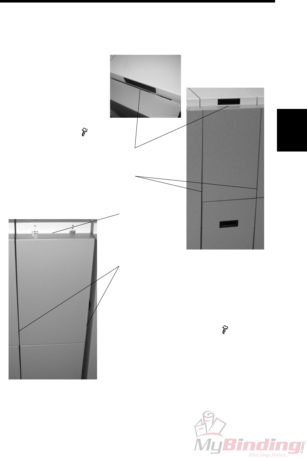
3.1.1 FRONT AND REAR COVER
Front Cover
1. Open the Top Cover.
2. Remove screw [A] ( x1)
3. Lift cover upwards to unhook
cover at the lower end [B].
[B]
[A]
[D]
Rear Cover
1. Open the Top Cover.
2. Remove screw [C] ( x1).
Similarly located as for the
Front Cover.
3. Lift cover upwards to unhook
cover at the lower end [D].
[C]
FTR-3-2
20 September 2006, Rev 0.01
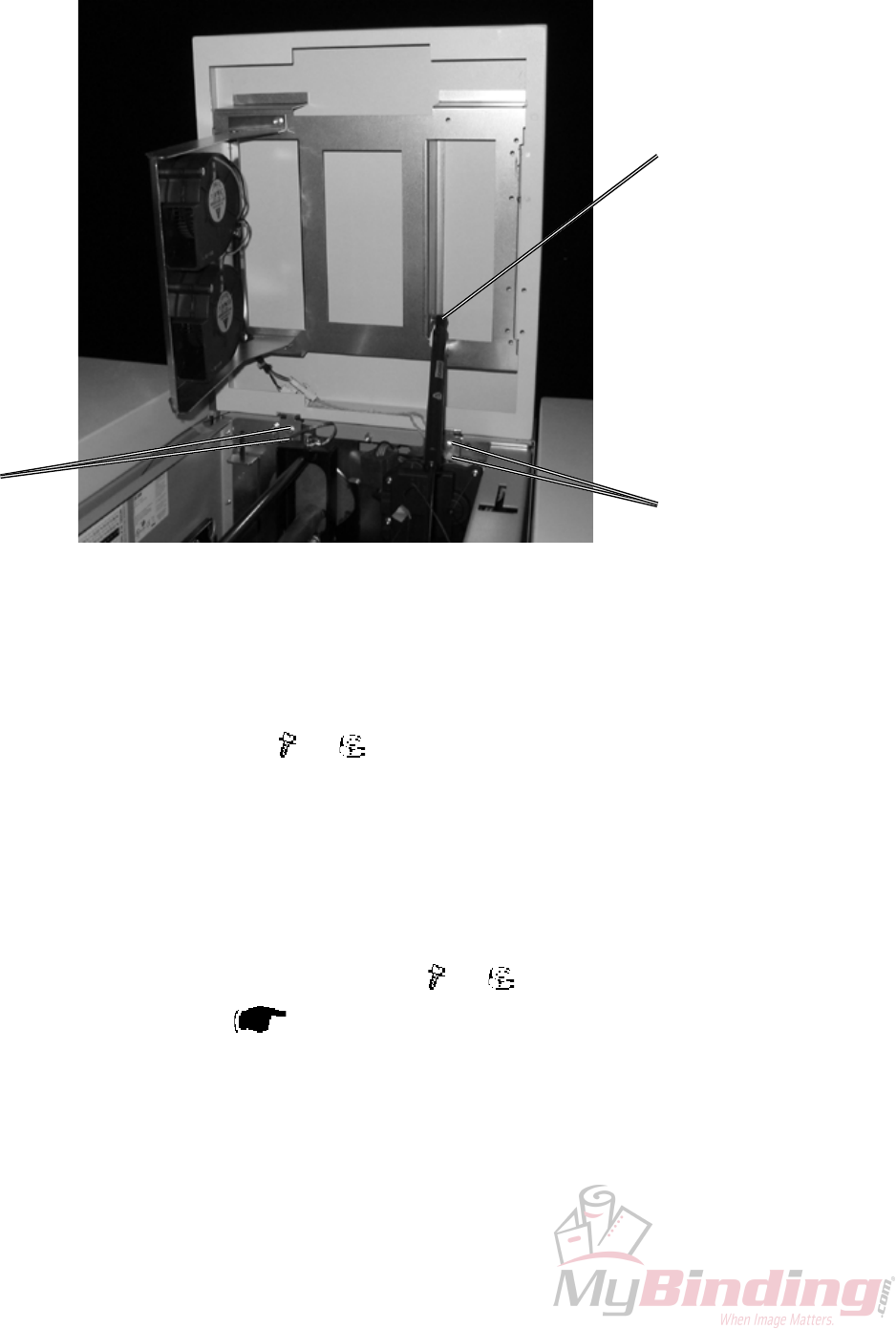
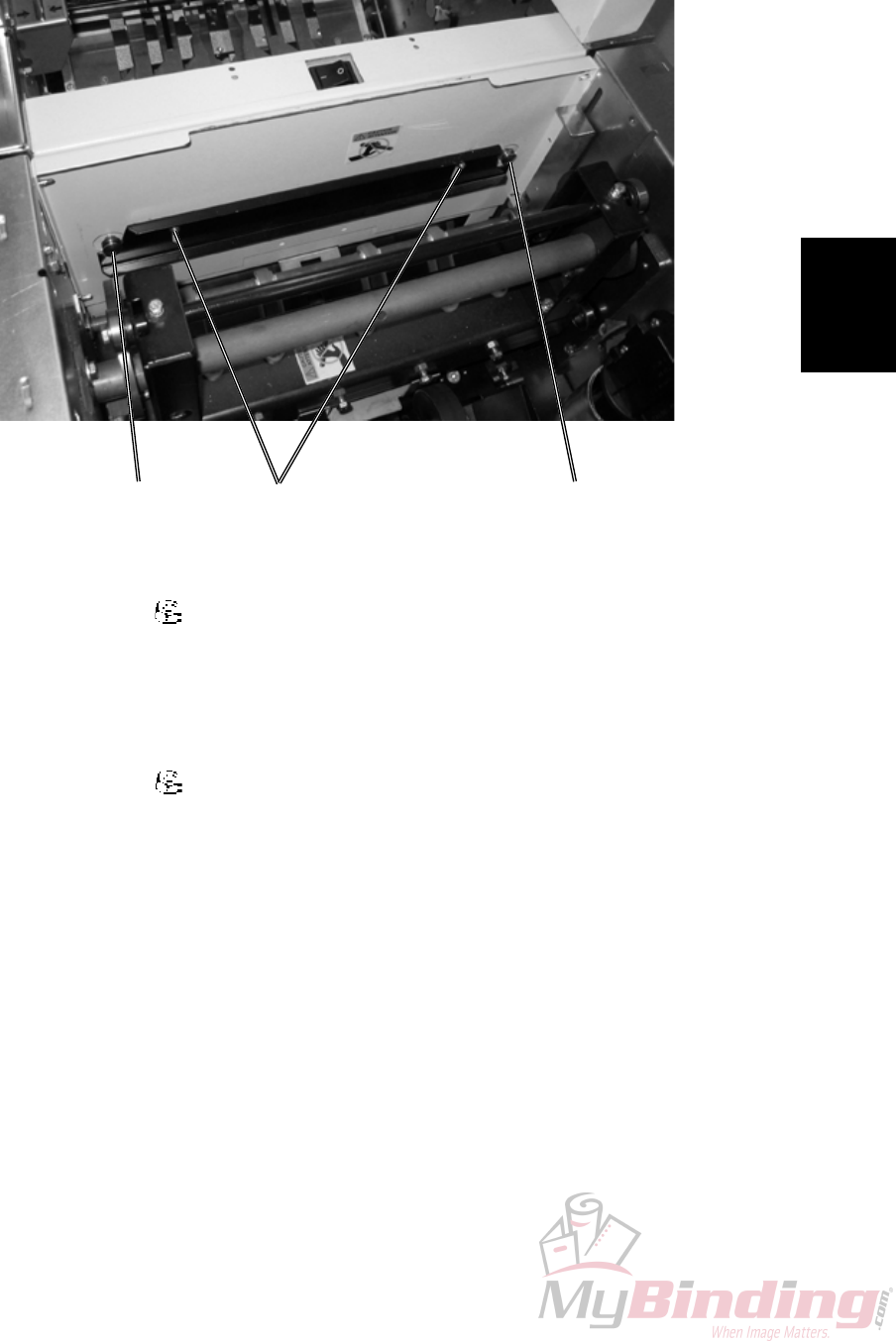
3.1.2 TOP COVER
COVERS
[A]
[B] [B]
Removal
1. Pry off the Gas spring [A] using a screw driver.
2. Loosen screws and nuts [B] ( x4, x4).
3. Lift out Cover upwards through cut-outs.
Replacement
1. Reverse the removal procedure.
Adjustment
1. Check that gap Top Cover to Frame is visually equal.
2. Adjust on screws and nuts [B] if necessary ( x4, x4). .
3. Adjust Interlock Switch ( 3.1.7).
Replacement
Adjustment
20 September 2006, Rev 0.01
FTR-3-3
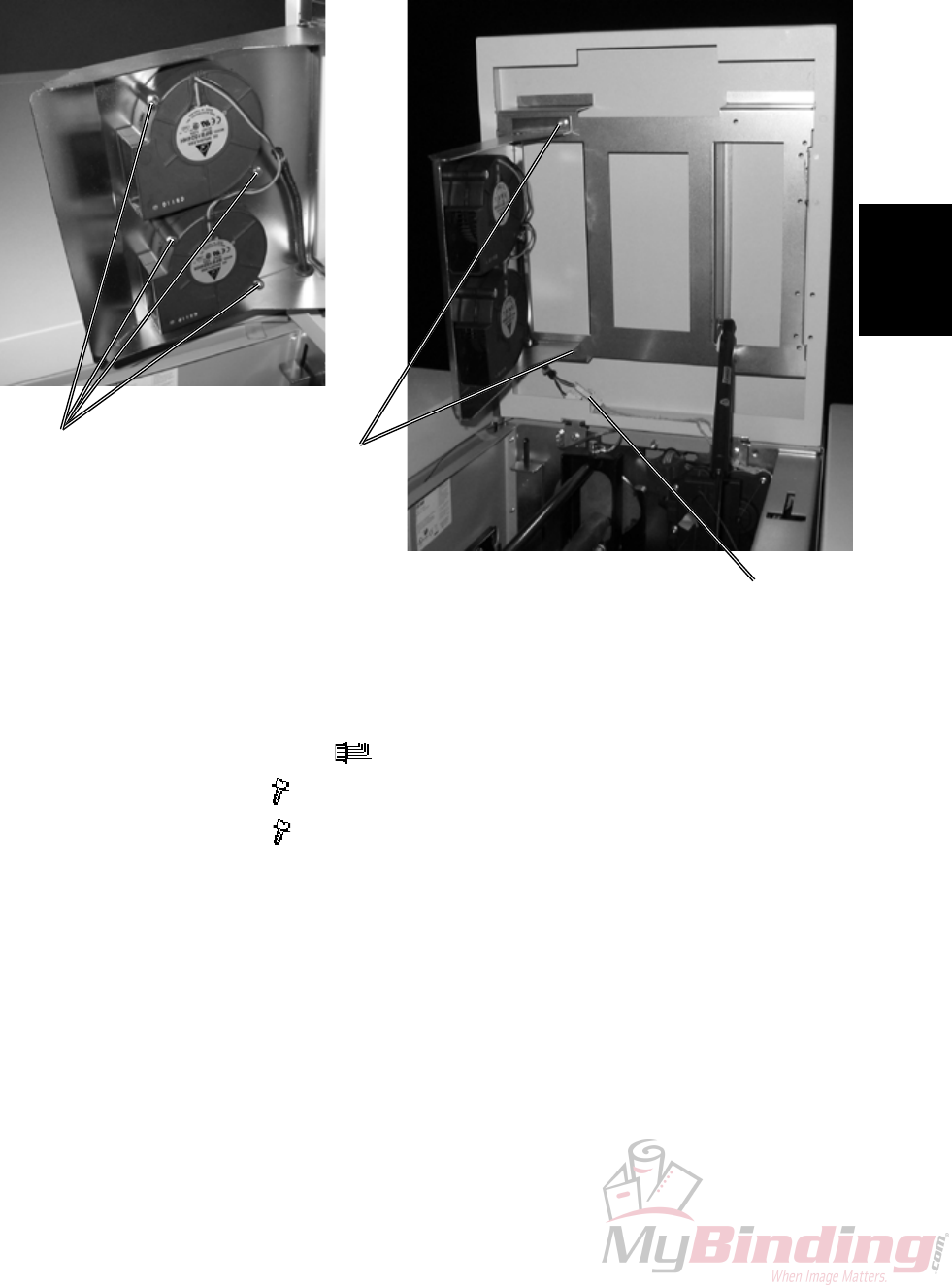
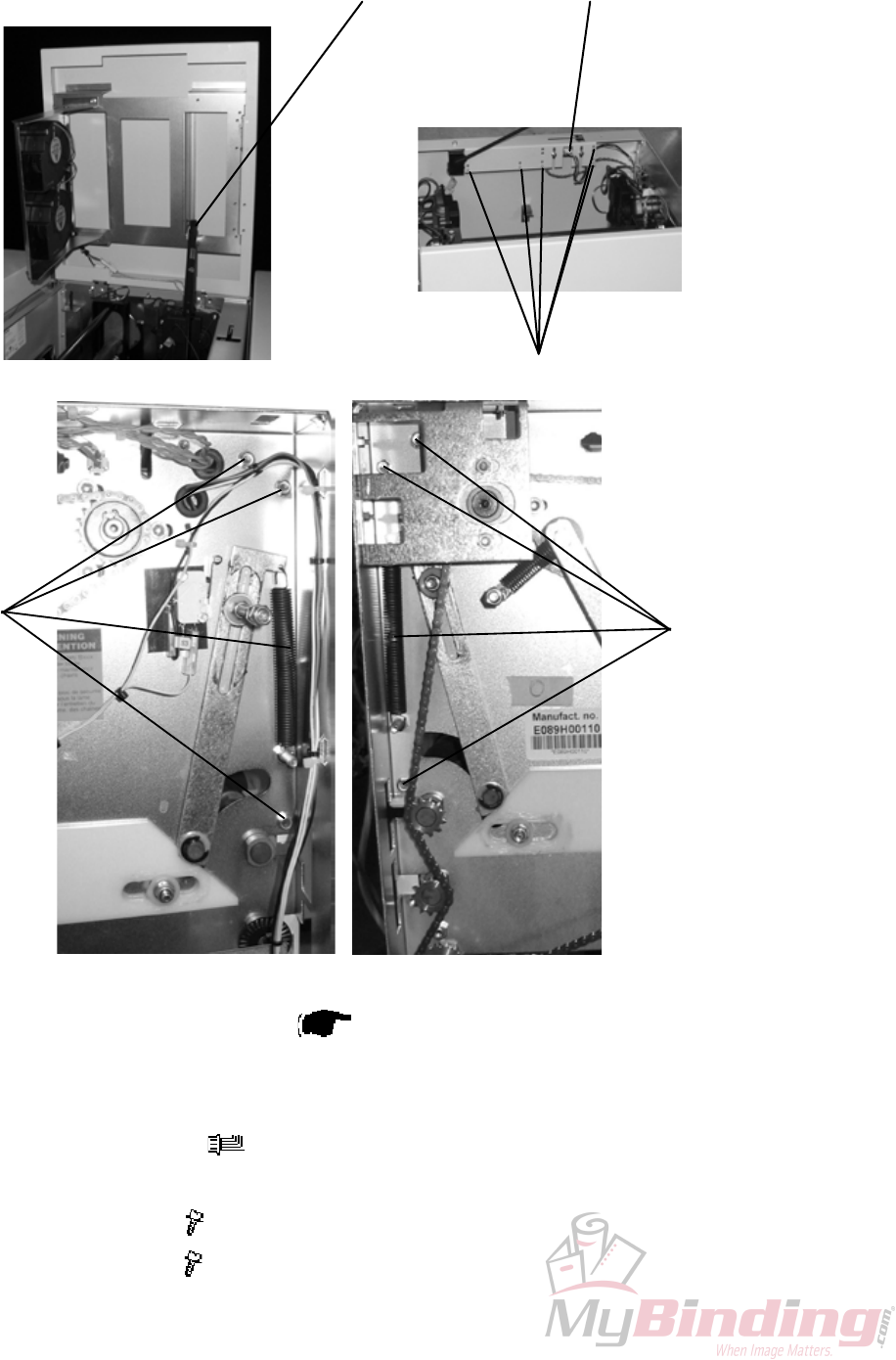
3.1.3 BLOWER MOTOR M5 / M6
COVERS
Removal
1. Open the Top Cover.
2. Disconnect connectors [A] ( x2).
4. Remove screws [B] ( x2).
5. Remove screws [C] ( x4).
Replacement
1. Reverse the removal procedure.
[A]
[B]
[C]
FTR-3-4
20 September 2006, Rev 0.01
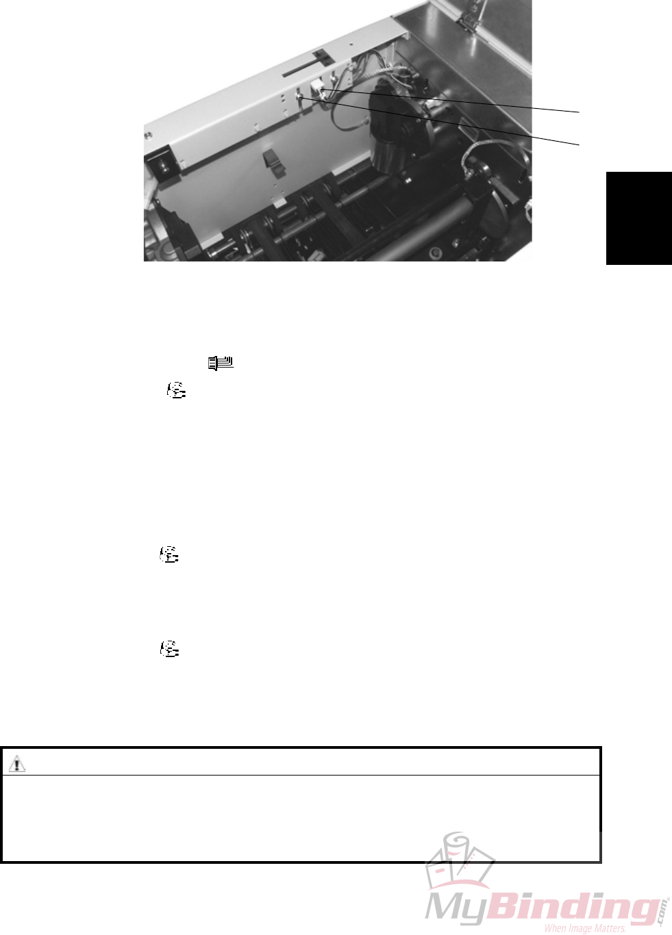
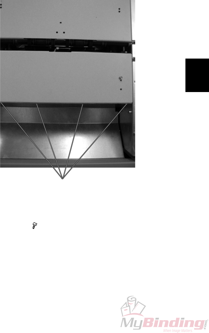
3.1.4 INFEED COVER
COVERS
[A]
1. Remove Front and Rear cover ( 3.1.1).
4. Remove screws [A] ( x3).
5. Remove screws [B] similar way as [A] ( x3).
[B]
Replacement
Adjustment
20 September 2006, Rev 0.01
FTR-3-5
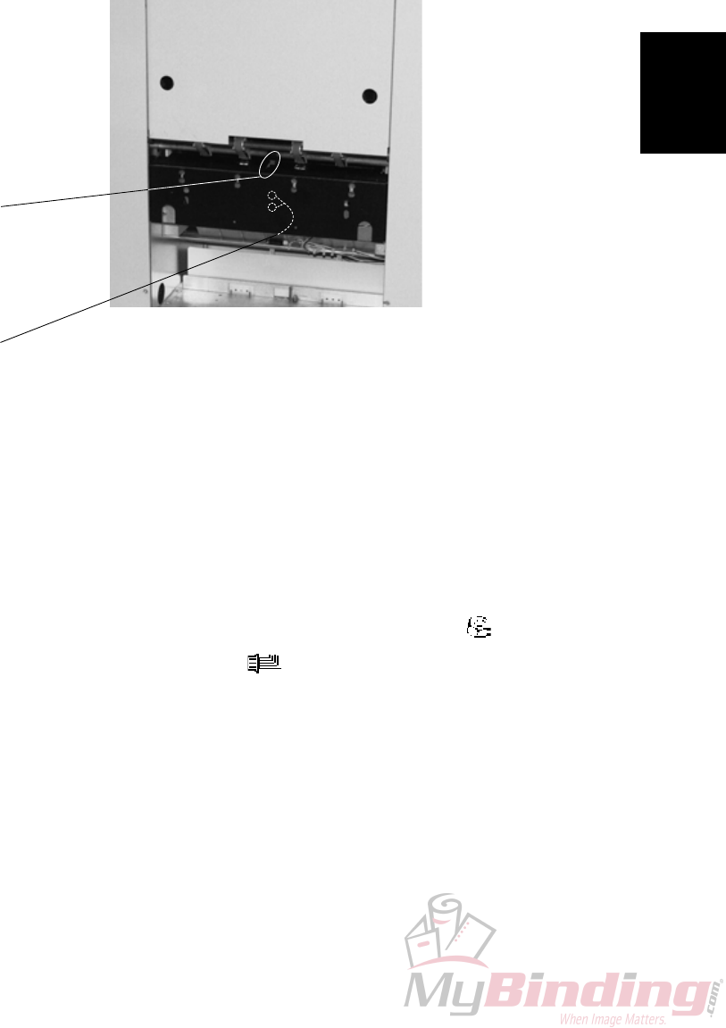
3.1.5 LOCKING BRACKET
COVERS
[A]
[B]
Removal
1. Loosen nuts [A] ( x2).
2. Locking bracket will fall down.
Replacement
1. Push Trimmer against Bookletmaker.
2. Push up Locking bracket so it latches studs [B].
3. Tighten nuts [A] ( x2).
[B]
FTR-3-6
20 September 2006, Rev 0.01
3.1.6 UPPER OUTFEED COVER
COVERS
1. Remove Belt stacker.
2. Remove Front and Rear cover ( 3.1.1).
3. Open the Top Cover.
4. Remove the Gas spring [A] by prying it off using a screw driver.
5. Remove connector [B] ( x1).
6. Cut cable ties [C] inside cover.
7. Remove screws [D] ( x5).
8. Remove screws [E] ( x5).
[A]
[C]
[B]
[D] [E]
Replacement
Adjustment
20 September 2006, Rev 0.01
FTR-3-7
3.1.7 INTERLOCK SWITCH S9 &S10
COVERS
Removal
1. Remove connector [B]( x1).
2. Remove nuts [A] ( x2).
Replacement
1. Reverse the removal procedure.
Adjustment
1. Loosen nuts [A] ( x2).
2. Adjust the interlock so that Top cover actuates interlock switch 2 mm before
closed.
NOTE: Make sure both rubber dampers contact the front cover when closed.
3. Tighten nuts [A] ( x2).
[A]
[B]
WARNING
Overriding or cheating the interlock allows the FTR 2000 system to operate
with the top cover open which can result in personal injury. Never give the
operator access to the cheater or show how ovverriding the interlock sys-
tem is carried out.
FTR-3-8
20 September 2006, Rev 0.01
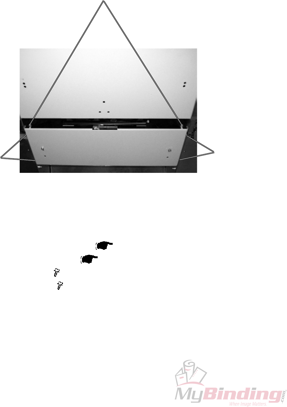
3.1.8 LOWER OUTFEED COVER
COVERS
1. Remove Belt stacker.
2. Remove Front and Rear cover ( 3.1.1).
3. Remove Protection Cover ( 3.1.9).
4. Loosen screws [A] ( x2).
5. Remove screws [B] ( x4).
[B]
[A]
[B]
Replacement
Adjustment
20 September 2006, Rev 0.01
FTR-3-9
3.1.9 PROTECTION COVER
COVERS
Removal
1. Loosen screws [A] ( x4).
2. Remove the cover through the key-holes.
[A]

Page intentionally blank
Replacement
Adjustment
20 September 2006, Rev 0.01
FTR-3-11
3.2 AREA C
3.2.1 INFEED SENSOR Q13
AREA C
1. Undock the Trimmer.
2. Remove nuts [A] inside bracket holding the Sensor bracket ( x2).
3. Remove connector from the Sensor ( x1).
4. Remove sensor [B].
[A]
[B]
FTR-3-12
20 September 2006, Rev 0.01
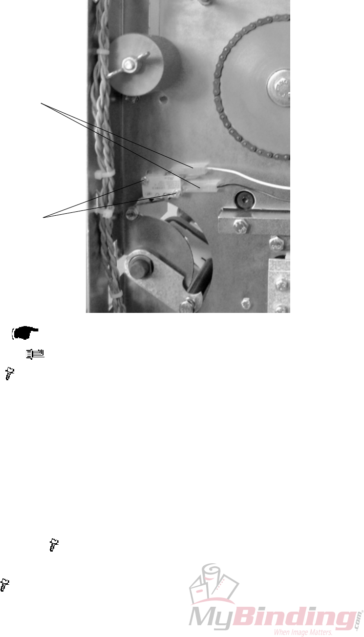
3.2.2 CONTROL SWITCH S2
AREA C
Removal
1. Remove Rear cover ( 3.1.1).
2. Remove connectors [A] ( x2).
3. Remove screws [B] ( x2 ).
Replacement
1. Reverse the removal procedure.
Adjustment
1. Lift the Infeed shaft.
2. Make sure the Switch activates slightly before the shaft latches in upper posi-
tion.
3. To adjust, loosen screws [B] ( x2 ).
4. Reposition switch to obtain adjustment.
5. Tighten screws [B] ( x2 ).
[A]
[B]
Replacement
Adjustment
20 September 2006, Rev 0.01
FTR-3-13
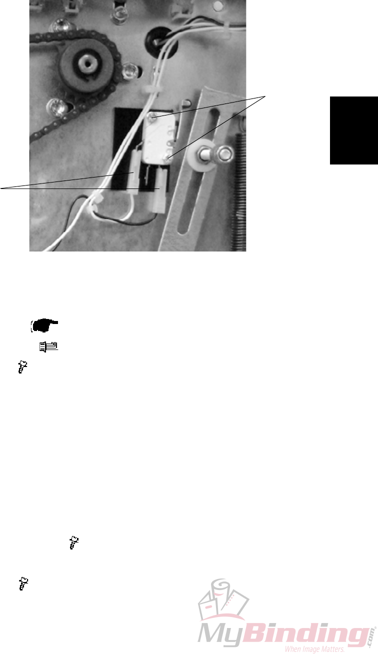
3.2.3 CONTROL SWITCH S3
AREA C
Removal
1. Remove Rear cover ( 3.1.1).
2. Remove connector [B] ( X2).
3. Remove screw [A] ( x2).
Replacement
1. Reverse the removal procedure.
Adjustment
1. Lift the compressing bracket.
2. Make sure the Switch activates approximately 10 mm from where the com-
pressing bracket latches in the upper position.
3. To adjust, loosen screws [A] ( x2 ).
4. Reposition switch to obtain adjustment.
5. Tighten screws [A] ( x2 ).
[A]
[B]
FTR-3-14
20 September 2006, Rev 0.01
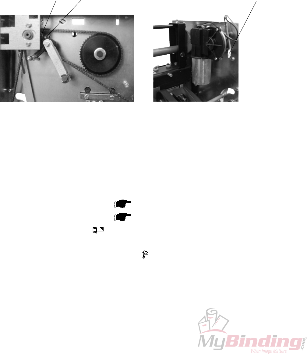
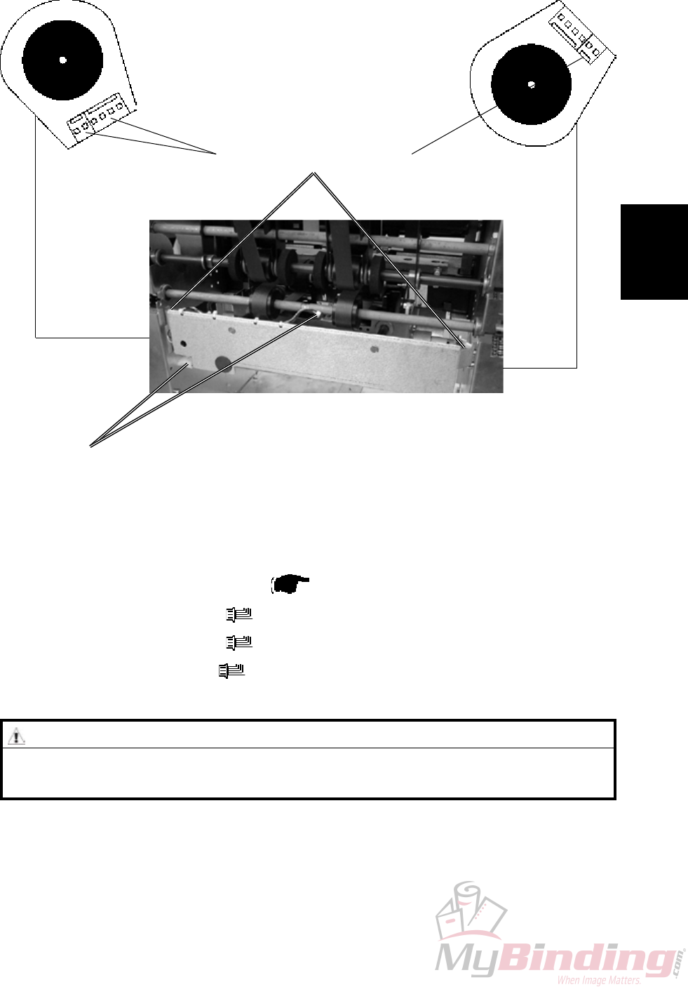
3.2.4 TRANSPORT MOTOR M1
AREA C
[A]
[B]
1. Remove Transmission chain ( 3.2.17).
2. Remove Knife support chain ( 3.2.18).
3. Remove connector [A] ( x1).
4. Grab the inner sprocket to pull out the whole sprocket assembly [B].
5. Remove screws [C] holding the motor ( x3).
NOTE: Hold the spacers between motor and frame when removing screws.
[C]
Replacement
Adjustment
20 September 2006, Rev 0.01
FTR-3-15
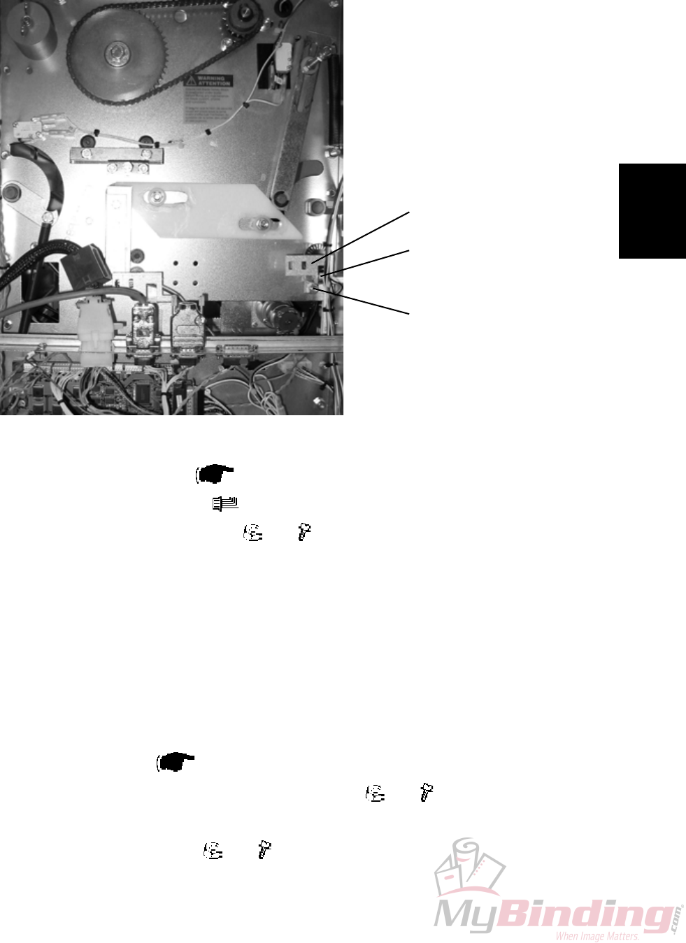
3.2.5 TRANSPORT BELT SENSOR Q4
AREA C
[A]
[B]
Removal
1. Remove Rear cover ( 3.1.1).
2. Remove connector [A] ( x1).
3. Remove nut and screw [B] ( x1, x1).
4. Remove bracket [C].
5. Squeeze the barbs of the sensor to remove.
Replacement
1. Reverse the removal procedure
NOTE: When tightening nut/screw make sure there is a space between en-
coder disc and sensor.
2. Enter service program mode and start the belts (motor M1). Check speed (m/
s) is registered ( Service Manual BM 2000: 5.1.1, 5.1.2).
3. If no, or erratic speed, loosen screw/nut [B] ( x1, x1).
4. Reposition sensor to obtain correct speed registration.
5. Tighten screw/nut [B] ( x1, x1).
[C]
FTR-3-16
20 September 2006, Rev 0.01
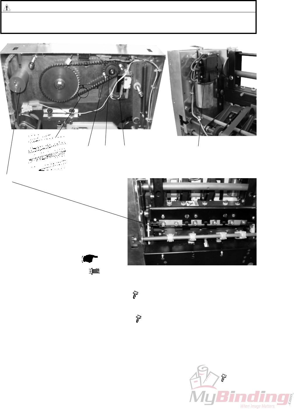
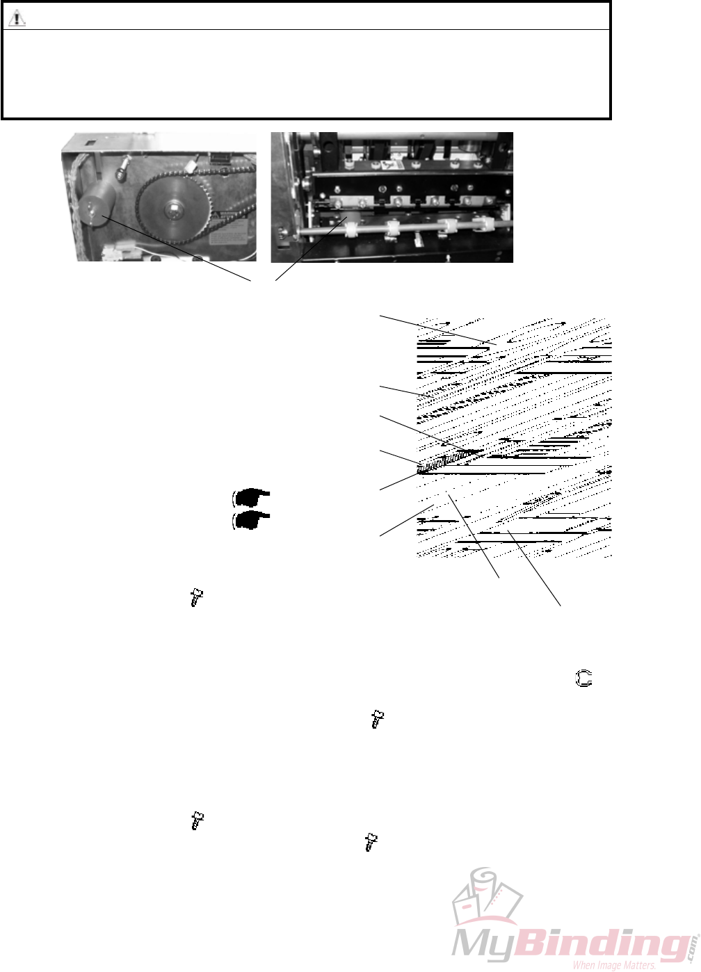
3.2.6 TRIM KNIFE MOTOR M2
AREA C
Removal
1. Remove Rear cover ( 3.1.1).
2. Remove connector [E] ( x1).
3. Remove circlip [C] using a circlip plier.
4. Loosen screws [A] holding the motor ( x3).
5. Remove sprocket [F].
6. Remove screws [A] holding the motor ( x3).
Replacement
1. If it is difcult to mount sprocket [F] remove master link [B].
2. Reverse the removal procedure.
3. Tension the chain so there is no slack when tightening screws [A] ( x3).
[B] [A] [C] [E]
[F]
WARNING
Place the safety block [D] between lower knife and upper knife beam. When
removing the chain nothing holds upper knife beam and knife in position.
[D]
Replacement
Adjustment
20 September 2006, Rev 0.01
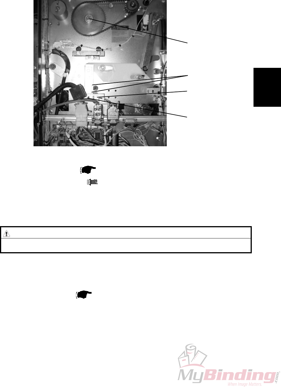
FTR-3-17
3.2.7 TRIM KNIFE HOME POSTITON SENSOR Q5
AREA C
[A]
[B]
Removal
1. Remove Rear cover ( 3.1.1).
2. Remove connector [A] ( x1).
3. Squeze the barbs of the sensor to remove.
NOTE: Gently pull bracket [B] to remove.
[C]
[D]
Replacement
1. Reverse the removal procedure.
2. Enter service program mode to check that sensor Q5 changes state when
blocked/unblocked ( Service Manual BM 2000: 5.1.1, 5.1.2).
NOTE: Do not cheat the interlock.
3. Move the Upper knife by turning crank [C] using a 13 mm wrench.
4. Check on the LCD that sensor Q5 changes state when blocked/unblocked by
actuators [D].
WARNING
Stay clear from upper knife. The knife edge may cause serious injuries.
FTR-3-18
20 September 2006, Rev 0.01
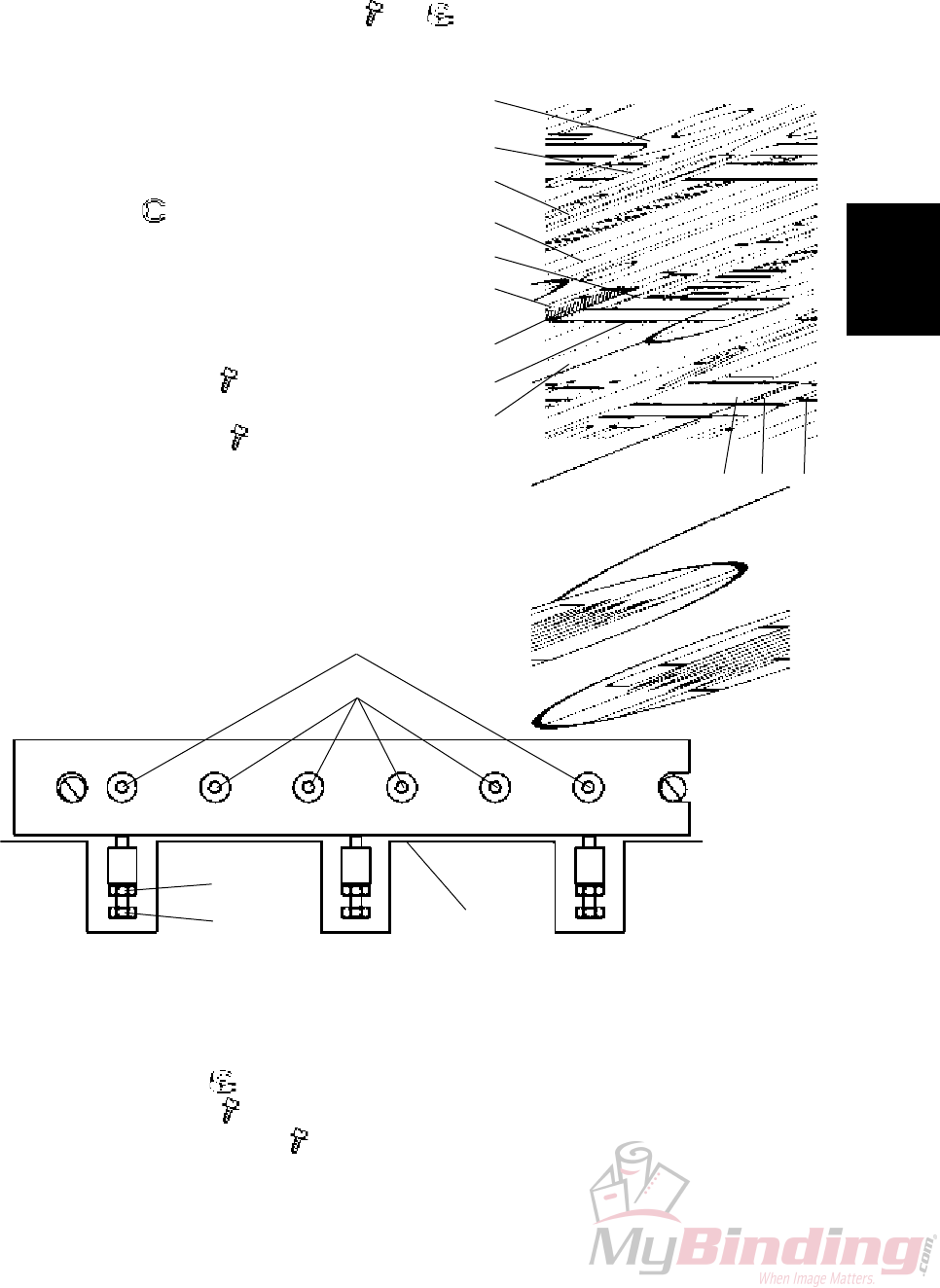
3.2.8 TRIM KNIFE
AREA C
WARNING
Stay clear from upper knife. The knife edge may cause serious injuries.
Place the safety block [A] between lower knife and upper knife beam. Keep
the safety block in that position as much time as possible throughout this
procedure.
[A]
Removal
1. Remove the belt stacker.
2. Undock the Trimmer.
3. Latch the compressing bracket in upper position.
4. Remove the infeed cover ( 3.1.4).
5. Remove protection cover ( 3.1.9).
Removal Upper knife
1. Remove screws [B] ( x3).
2. Remove knife protection plate [C].
3. Move transport protection from the new to the old knife or use the transport
protection attached behind the front cover.
4. Remove the e-clip [D] from the middle plunger, to release the Set clamp (
x1).
5. Remove screws [E] and cup spring washers ( x6).
NOTE: When removing screws [E] the nuts [G] will fall down through the cut-
out in bottom of knife beam.
Removal Lower knife
1. Remove screws [H] ( x4).
2. Remove screws [I] and cup spring washers ( x2).
[C]
[E]
[F]
[D]
[G]
Lower knife
[B]
Upper knife
Replacement
Adjustment
20 September 2006, Rev 0.01
FTR-3-19
Replacement Upper knife
1. Move transport protection from the old to the new knife.
2. Clean and apply grease on guide bars [J] and side guides [K].
3. Fit upper knife onto guide bars [J].
Apply grease on the cup spring washers [F] closest to the knife.
Mount screws [E] with nuts [G] ( x6, x6).
NOTE: Make sure each screw has 7 cup spring washers placed accord-
ing to gure.
4. Remove transport protection and mount
it on the old knife.
5. Mount knife protection plate [C].
6. Mount the set clamp in position with
e-clip [D] ( x1) .
Replacement Lower knife
1. Place the lower knife onto the lower knife
beam.
2. Apply grease on both washers.
3. Mount screws [I] ( x2) and cup spring
washers.
4. Mount screws [H] ( x4).
[K]
[J]
[O]
[N] [L]
[H]
[M]
[L]
[N]
[I]
[E]
[F]
[B]
[D]
[G]
[C]
[M]
Adjustment
1. Turn screws [E] so there is no tension and no play between cup spring wash-
ers and upper knife.
2. Then turn screws [E] one revolution clockwise each.
3. Loosen nuts [L] ( x3)
4. Turn screws [M] ( x3) counter clockwise until they passes edge [N].
5. Loosen screws [I] & [H] ( x6).
6. Push the Lower knife against the bracket [N].
12435 6
AREA C
FTR-3-20
20 September 2006, Rev 0.01
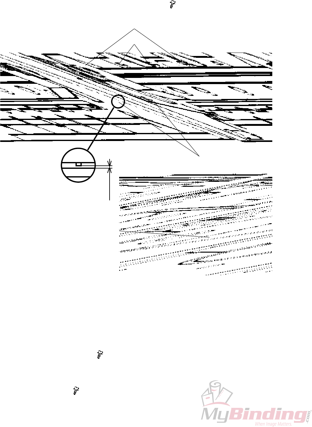
7. Use a feeler gauge and check that the space [Q] between upper knife and the
two red marked reference screws in the middle [P] is 0.50 mm.
NOTE: Never touch the red painted reference screws [P].
8. Adjust the space if necessary with screws [O] ( x2).
[O]
[Q]
0.50 mm
[P]
9. Bring the Upper knife down to the bottom position by turning crank [R] using a
13 mm wrench.
NOTE: When bringing the Upper knife down, make sure it does not touch the
Lower knife.
10. Gently push in the Lower knife against the Upper knife.
NOTE: Listen that it touches on both sides.
11. Raise the upper knife to the top position by turning crank [R].
12. Tighten screws [I] & [H] ( x6).
NOTE: Tighten a little at rst according to the sequence 1-6. Then tighten a lit-
tle harder to nally fully tighten the screws. Always according to the sequence
1-6.
13. Turn screws [M] ( x3) so they touch the lower knife.
[R]
AREA C
Replacement
Adjustment
20 September 2006, Rev 0.01
FTR-3-21
13. Slowly and carefully without paper lower the upper knife by turning crank [R].
Check that the upper knife does not contact the lower knife. In that case, back
up the upper knife and start over from step 3. If no contact proceed to the bot-
tom position.
NOTE: Look through the cut out in the side frames while turning crank.
14. Make 5 different booklets in the BM 2000 required for the adjustment. The
booklets should have 2, 15, 20 & 25 sheets A3 (11“x17“) 80 gsm (20# bond).
15. Place the 2 sheet booklet in cutting position.
Trim the set by turning crank [R].
Inspect the trim result. Check if the lowest sheet of the booklet is cut clean
throughout the length.
If good, trim and inspect the 15 sheet booklet the same way.
If good, trim and inspect the 20 sheet booklet the same way.
If the set is not correctly cut on one of the ends, loosen the ve screws [I] & [H]
on the bad end and keep the one screw [I] tightened at the good end.
Turn screw [M] on the bad end 1/36 revolution or 10° clockwise ( x1).
16. Repeat from step 11 until trim result is perfect.
NOTE: As guidance, trim the over spec. 30 sheet booklet to clearer see if and
where it does not cut clean.
17. If not correctly cut in the middle, loosen the four screws [H] and keep the
screws [I] tightened.
Turn screw [M] in the middle 1/72 revolution or 5°clockwise ( x1).
Repeat from step 11.
NOTE: If the knife/knives has been damaged, they have to be replaced or
resharpened even if a correct result is obtained, due to shortened life time.
18. Tighten the lock nuts [L] without turning screws [M] ( x3).
19. Reverse removal procedure step 1-5.
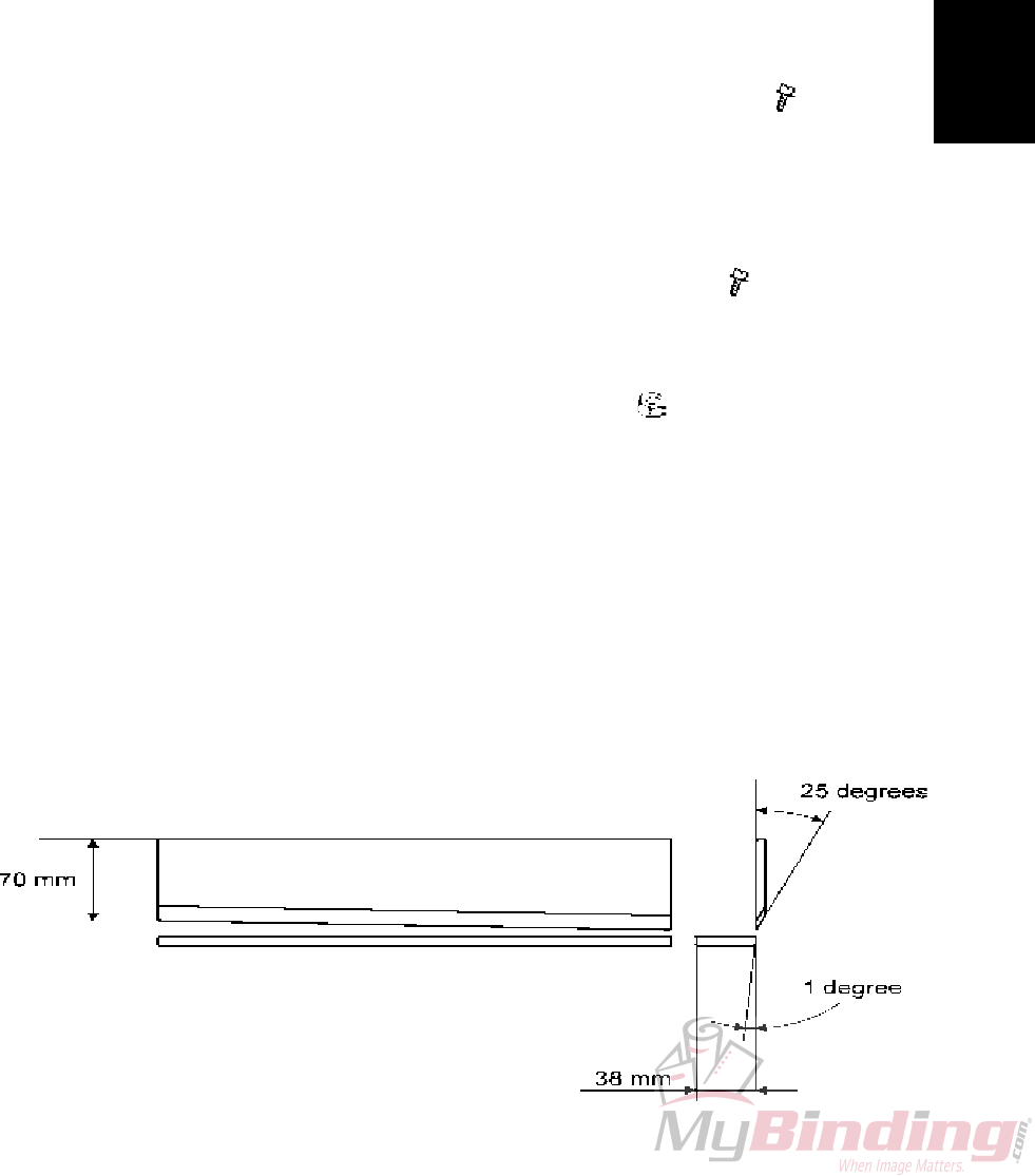
NOTE: When the knives become dull it is possible to resharpen them.
The upper knife can be resharpened until it is 70 mm (2”3/4) wide at the short-
er end. Resharpen at a 25° angle.
The lower knife can be resharpened until it is 38 mm (1”½) wide.
Resharpen at a 1° angle.
AREA C
FTR-3-22
20 September 2006, Rev 0.01
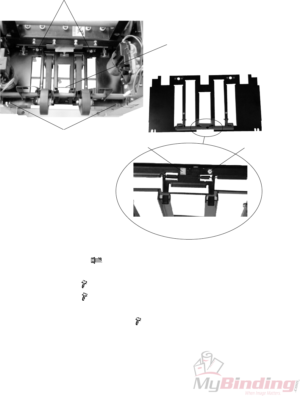
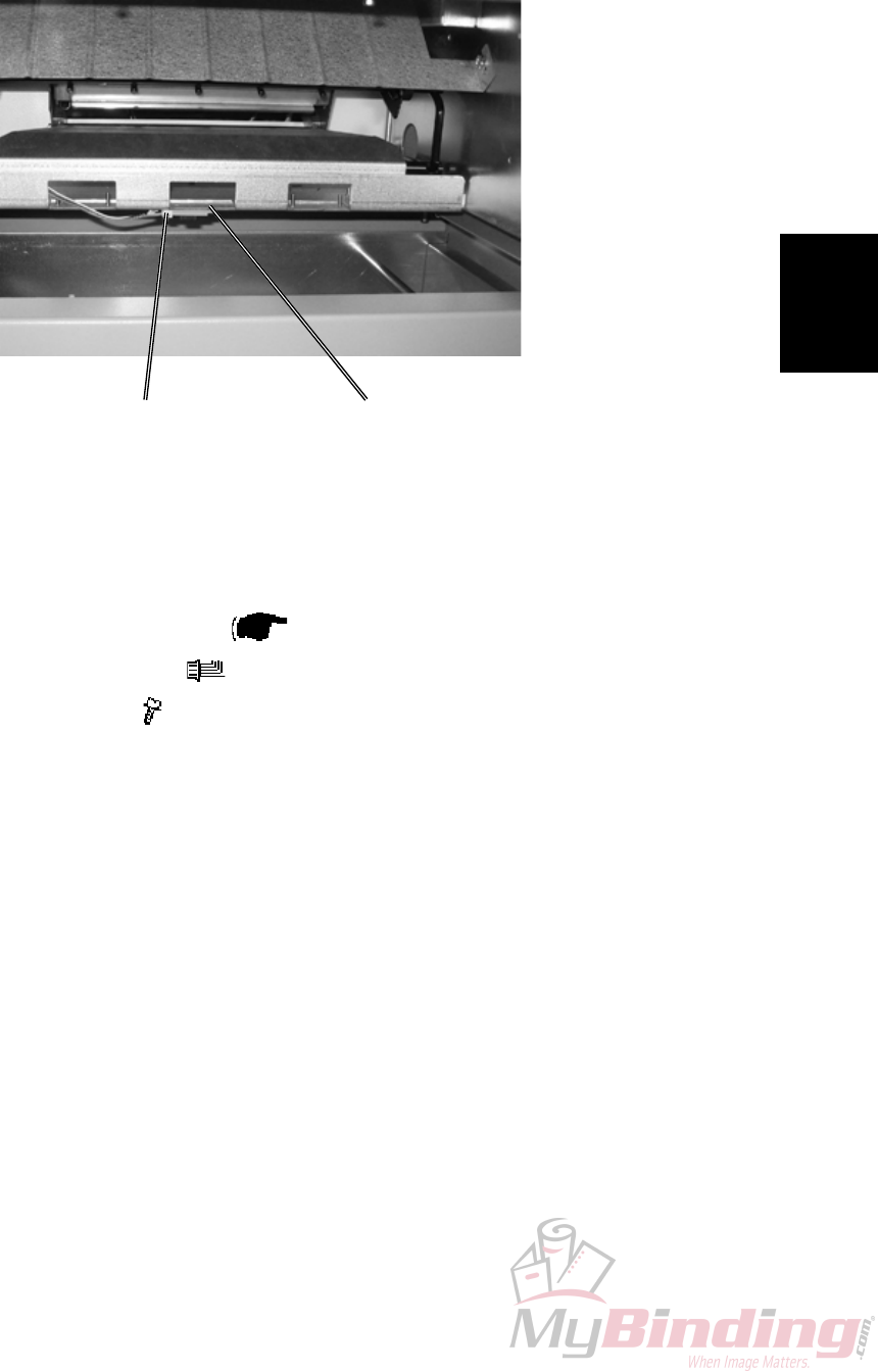
3.2.9 PAPER PATH & OUTFEED SENSOR Q6
AREA C
1. Remove connector [D] ( x1).
2. Lift up and latch compressing bracket [B].
3. Remove screws [A] ( x2).
4. Remove screws [C] ( x2).
5. Pull Paper path out through the outfeed.
6. To remove sensor, remove screw [E] ( x1).
[A]
[C]
[B]
[D] [E]
Replacement
Adjustment
20 September 2006, Rev 0.01
FTR-3-23
3.2.10 STOP GATE CARRIAGE
AREA C
Removal
1. Before switching off the power,
set the Trimmer (Paper size) to A4 / 8.5x11” and Trimming to off.
2. Remove Lower outfeed cover ( 3.1.8).
3. Remove connectors [A] ( x2).
4. Remove connectors [B] ( x2).
5. Remove connector [C] ( x1).
6. Pull out the Carriage gently.
[A]
[B] [C]
[D]
CAUTION
When removing the Carriage, watch out so the motor connectors [B] & [C]
do not get damaged by the side frame cut-outs.
Replacement
1. When positioning the carriage in place, make sure the two sliding rods and the
gear rack enters their holes and slot.
2. Reverse the removal procedure.
FTR-3-24
20 September 2006, Rev 0.01
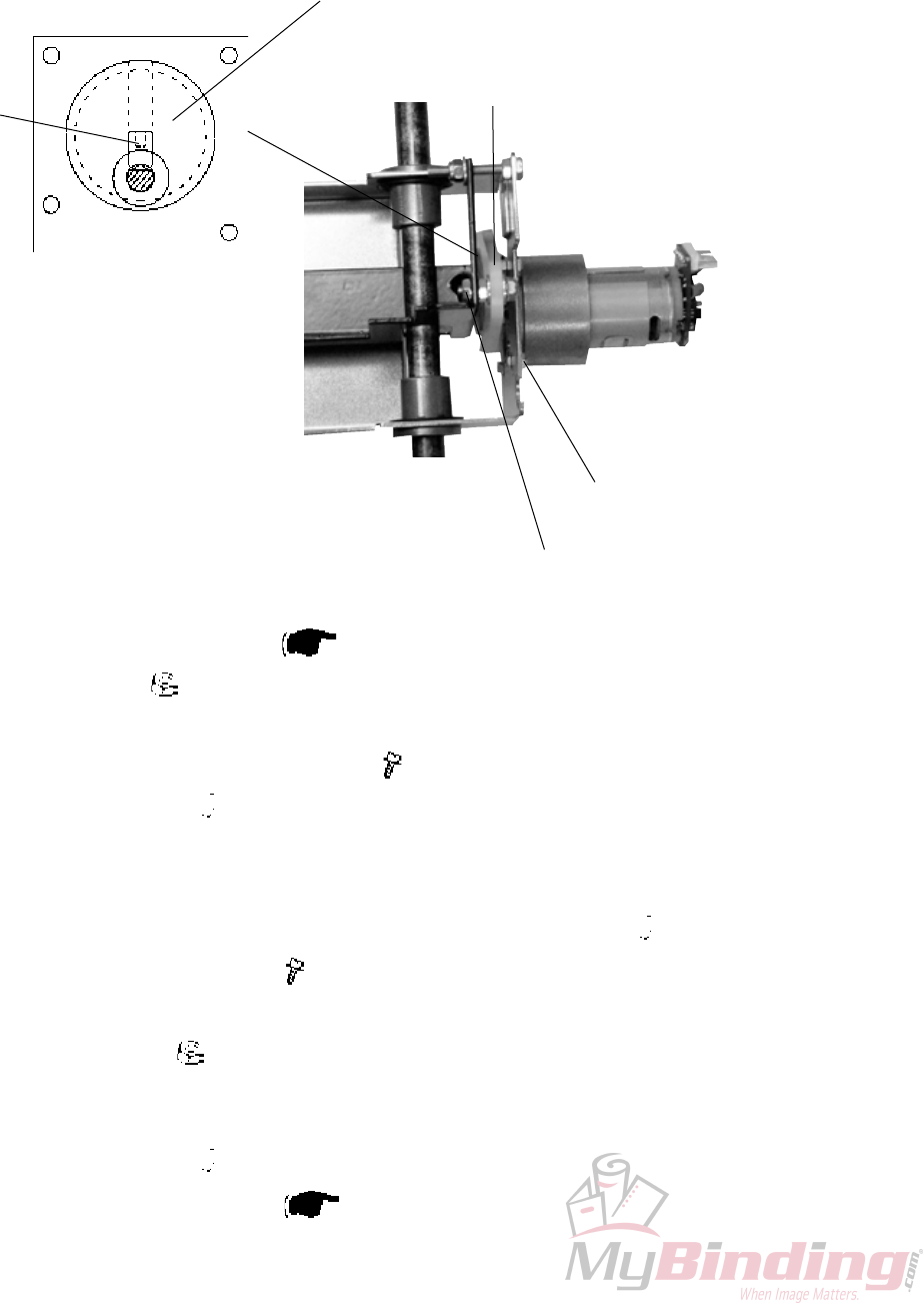
3.2.11 STOP GATE MOTOR M3 & SENSOR Q7
AREA C
Removal
1. Remove Stop gate carriage ( 1.2.10).
2. Remove nut [A] ( x1).
3. Remove Crank arm [B].
4. Remove screws [C] holding the motor ( x4).
5. Loosen set screw [D] ( x1).
Replacement
1. Mount the Crank pulley [E] without tightening the set screw [D] ( x1).
2. Mount motor with screws [C] ( x4).
3. Mount Crank arm [B].
4. Tightening nut [A] ( x1).
NOTE: Make sure play for Crank arm [B] is maintained.
5. Position the Crank pulley [E] so it is aligned with Crank arm [B].
6. Tighten set screw [D] ( x1) on the at of the shaft..
7. Reinstall Stop gate carriage ( 3.2.10).
[A]
[D]
[C]
[B]
[E]

Replacement
Adjustment
20 September 2006, Rev 0.01
FTR-3-25
3.2.12 LENGTH ADJUSTMENT MOTOR M4 & SENSOR Q12
AREA C
1. Remove Stop gate carriage ( 3.2.10).
2. Unhook spring [A].
3. Remove screws [B] holding the motor ( x4).
[A]
[B]
FTR-3-26
20 September 2006, Rev 0.01
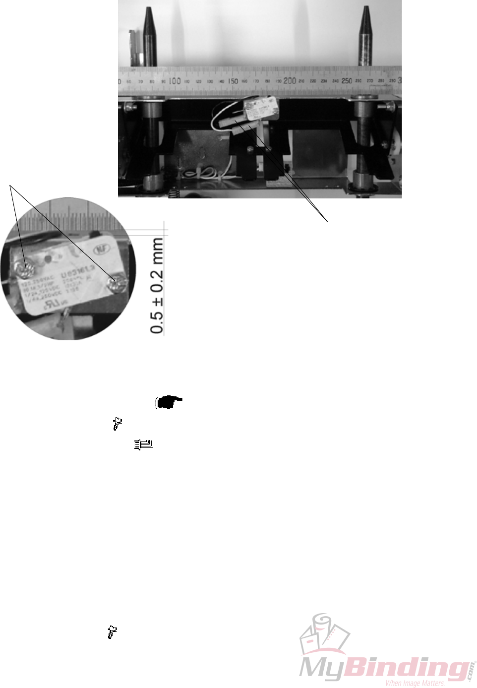
3.2.13 LENGTH ADJUSTMENT HOME POSITION SWITCH S11
AREA C
Removal
1. Remove Stop gate carriage ( 3.2.10).
2. Remove screws [B] ( x2).
3. Remove connectors [A] ( x2).
Replacement
1. Reverse the removal procedure.
Adjustment
1. Place a ruler across the slide rods and up against the ange bushings
[Picture 1].
2. Position the switch so it is activated by the ruler and
so there is a 0.5 mm ± 0.2 mm gap between switch body and ruler [Picture 2].
3. Tighten screws [B] ( x2).
[A]
[B]
[Picture 1]
[Picture 2]
Replacement
Adjustment
20 September 2006, Rev 0.01
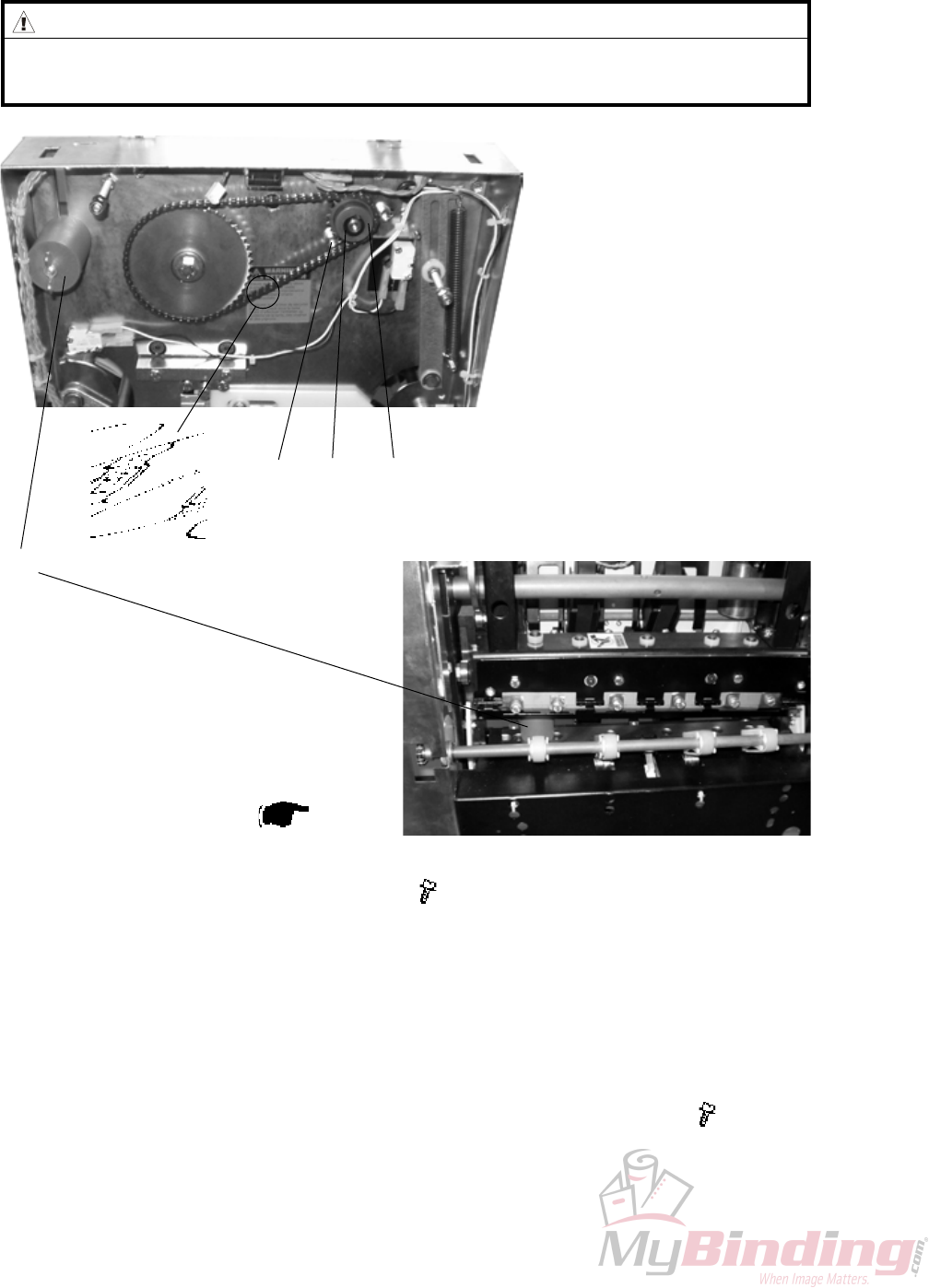
FTR-3-27
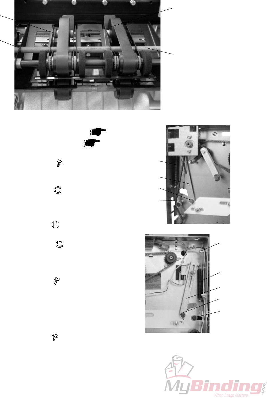
3.2.14 LOWER OUTFEED BELTS
AREA C
Removal
1. Remove Stop gate carriage ( 3.2.10).
2. Remove Paper path ( 3.2.9).
3. Remove Transmission chain ( 3.2.17).
4. Remove screws [B] ( x2).
5. Remove e-clip [C] ( x1).
6. Slide Flange bushing [C] towards the center of the shaft and tilt the shaft out
through the cut-out in the side frame.
Replacement
1. Reverse the removal procedure.
Adjustment
1. Loosen screws [B] ( x2).
2. The belts should be adjusted so they have no slack and even tension.
3. Pull shaft [D] to obtain adjustment and tighten screws [B] ( x2).
[B]
[C]
[B]
[A]
[D]
FTR-3-28
20 September 2006, Rev 0.01
3.2.15 UPPER OUTFEED BELTS
AREA C
Removal
1. Remove Belt stacker.
2. Remove Front and Rear cover ( 3.1.1).
3. Remove Transmission chain ( 3.2.17).
4. Unhook springs [A] (x2).
5. Remove screws [B] ( x6).
NOTE: Leave the screw at the top on each side
for the outfeed cover to pivot around.
6. Remove e-clip [C] ( x2).
Remove nylon washer [C] (x2).
Unhook link arm [D] (x2).
Remove needle bearing [C] (x2).
7. Remove e-clip [E] ( x2).
8. Pull out shaft [F].
9. Remove e-clips [G] ( x2) inside frames.
10. Slide Flange bushings [G] towards the center of
the shaft and pull out the whole assembly th-
rough the outfeed.
11. Loosen screws [H] ( x4) and remove belts.
Adjustment
1. The belts should be adjusted so they have no
slack and even tension.
2. Pull runner pulleys [I] to obtain adjustment and
tighten screws [H] ( x4).
Replacement
1. Reverse the removal procedure.
[E]
[H] [I]
[F]
[A]
[D]
[C]
[G]
[A]
[D]
[C]
[G]
[B]
Replacement
Adjustment
20 September 2006, Rev 0.01
FTR-3-29
3.2.16 TRIM BIN FULL SENSOR Q8
AREA C
[A]
[B]
1. Undock the Trimmer.
2. Remove Protection Cover ( 3.1.9).
3. Remove connector [B] ( x1).
4. Remove screw [A] ( x1).
FTR-3-30
20 September 2006, Rev 0.01
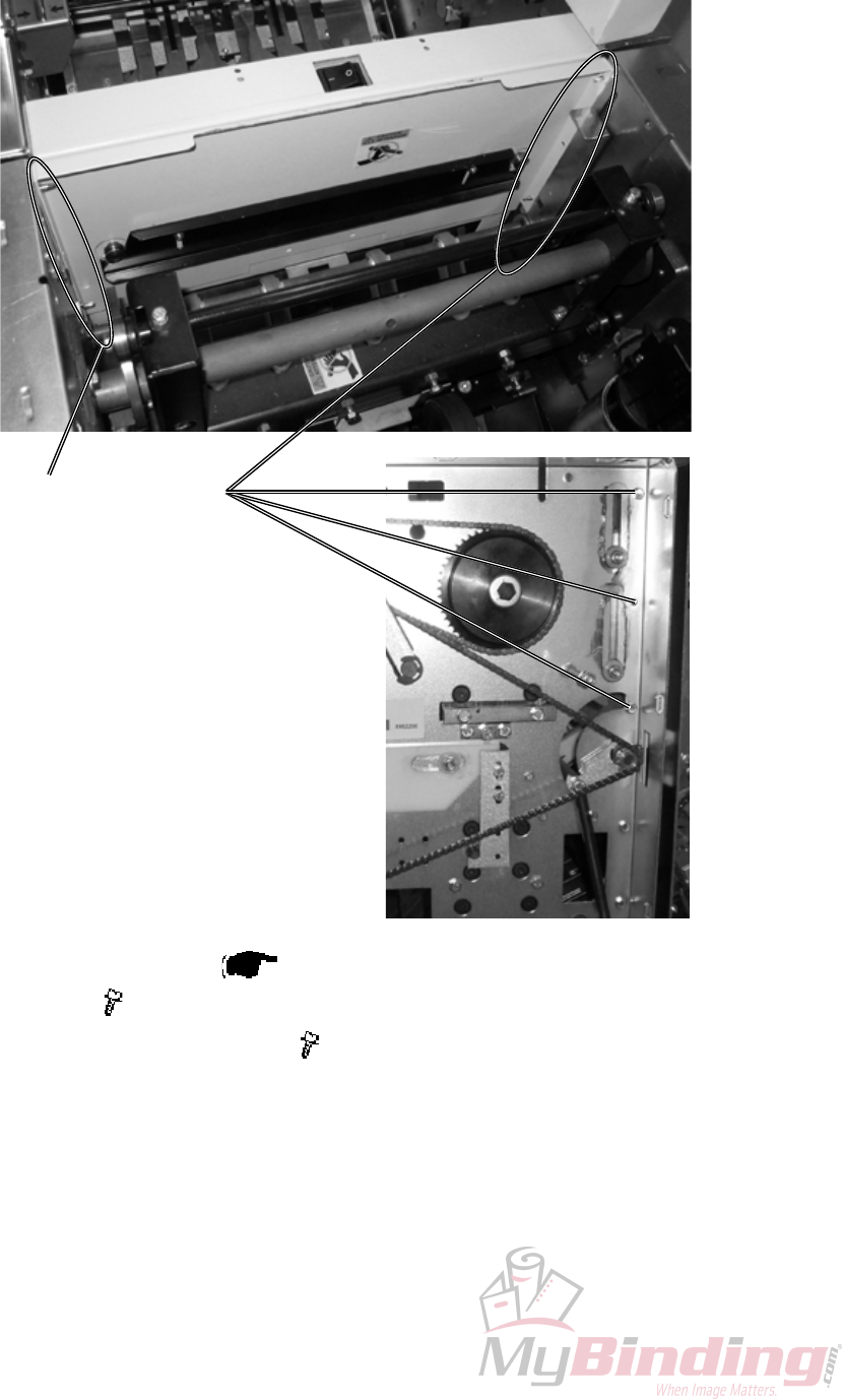
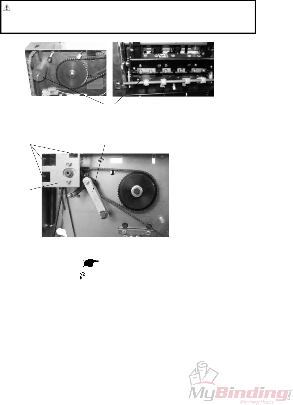
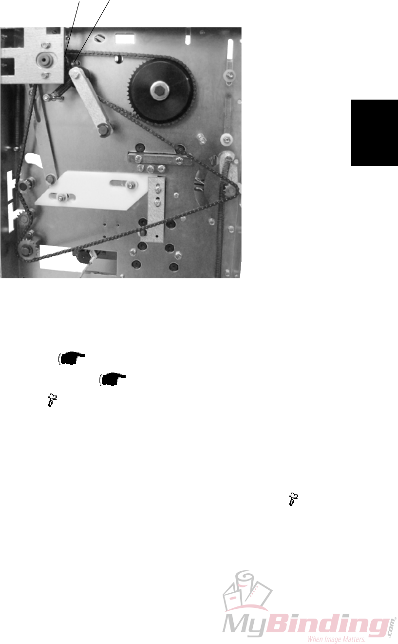
3.2.17 TRANSMISSION CHAIN
AREA C
WARNING
Place the safety block [D] between lower knife and upper knife beam. When
removing the chain nothing holds upper knife beam and knife in position.
[D]
[A]
[B]
[C]
1. Remove Front cover ( 3.1.1).
2. Remove screws [A] ( x3).
3. Remove bracket [B].
4. Pull Tensioner [C] to release tension when removing chain.
Replacement
Adjustment
20 September 2006, Rev 0.01
FTR-3-31
3.2.18 KNIFE SUPPORT CHAIN
AREA C
[A]
[B]
1. Remove Front cover ( 3.1.1).
2. Remove Transmission chain ( 3.2.17).
3. Loosen screws [A] ( x3).
4. Remove chain from sprocket [B].
Replacement
1. Reverse the removal procedure.
2. Tension the chain so there is no slack when tightening screws [A] ( x3).
FTR-3-32
20 September 2006, Rev 0.01
3.2.19 KNIFE CHAIN
AREA C
Removal
1. Remove Rear cover ( 3.1.1).
2. Remove retaining ring [A].
3. Loosen screws [B] holding the motor ( x3).
4. Remove sprocket [C].
Replacement
1. If it is difcult to mount sprocket [C] remove master link [E].
2. Reverse the removal procedure.
3. Tension the chain so there is no slack when tightening screws [B] ( x3).
[E] [B] [A] [C]
WARNING
Place the safety block [D] between lower knife and upper knife beam. When
removing the chain nothing holds upper knife beam and knife in position.
[D]
Replacement
Adjustment
20 September 2006, Rev 0.01
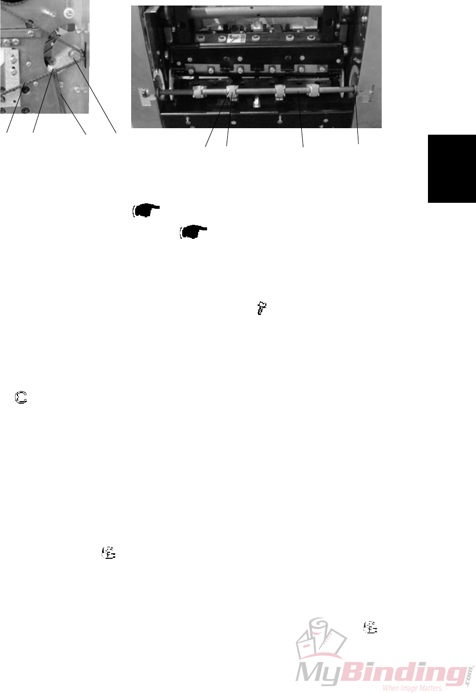
FTR-3-33
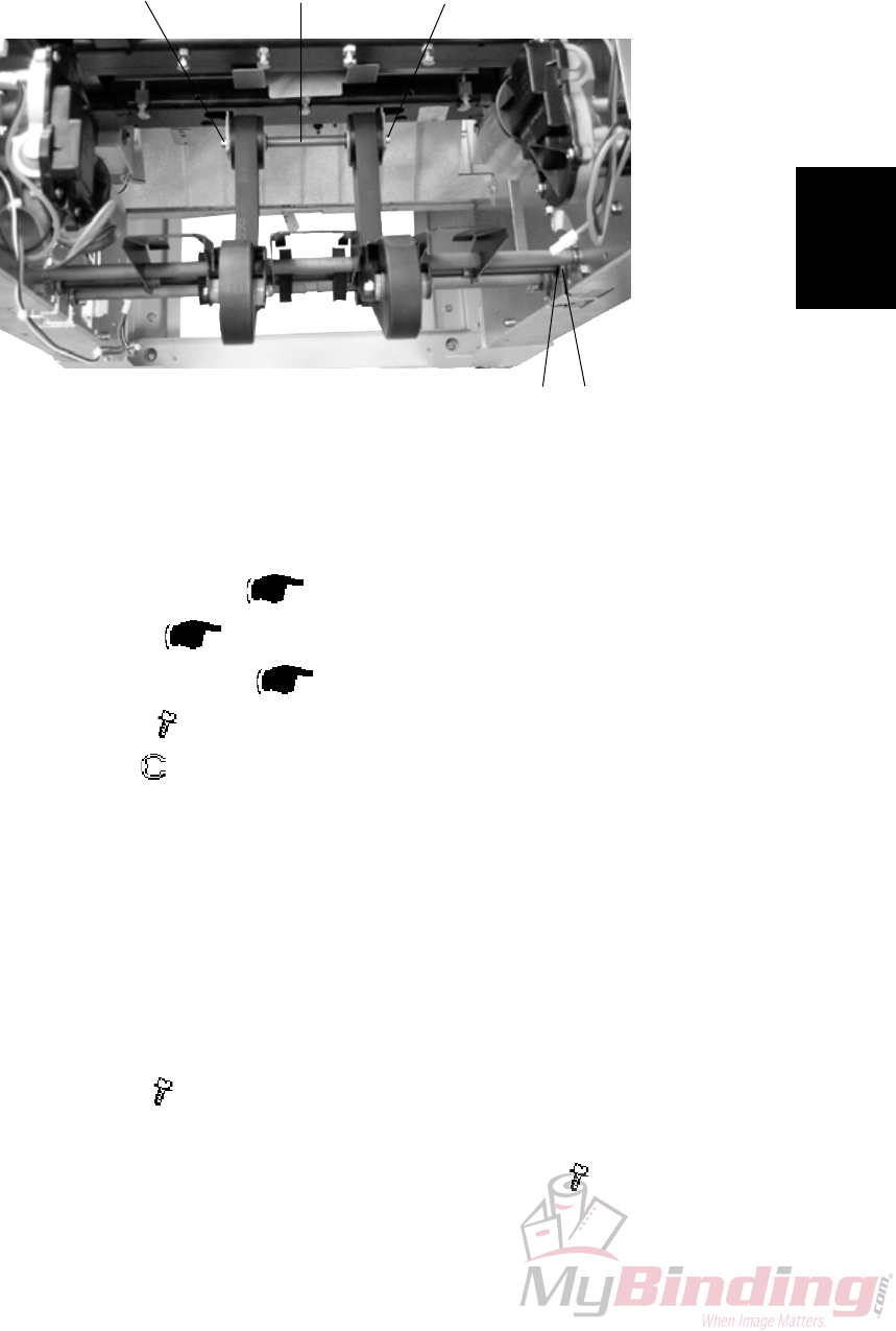
3.2.20 INFEED BELTS
Removal
1. Undock the Trimmer.
2. Remove Infeed cover ( 3.1.4).
3. Remove Front and Rear cover ( 3.1.1).
4. Unhook Transmission chain [E] from sprocket [F].
NOTE: Unhooking chain from outfeed shaft sprockets rst to gain more slack.
5. Unhook Springs [A] on both ends of the shaft (x2).
6. Remove screws [B] on both ends of the shaft ( x2) .
7. Remove Plastic retaining clips [G] (x8).
8. Remove Belts [D] (x4) from Lever shaft [H].
NOTE: Move the belts to one end and the lever shaft to the opposite end.
9. Remove e-clip [C] and slide ange bushing towards the center of the shaft.
( x1)
10. Tilt the shaft out through the cut-out in the side frame on that end to
remove the Belts [D] (x4).
Replacement
1. Reverse the removal procedure.
Adjustment
1. Loosen nuts [B] ( x2) slightly.
2. Place a piece of paper (80 gsm) between the two center belts and the ball
bearings.
3. Pull the sheet a little, by each of the center belts to verify even pressure.
4. Unskew shaft until even pressure is obtained and tighten nuts [B] ( x2).
[A]
[B] [C]
[D]
[E] [F] [G] [H]
AREA C

Page intentionally blank
Replacement
Adjustment
20 September 2006, Rev 0.01
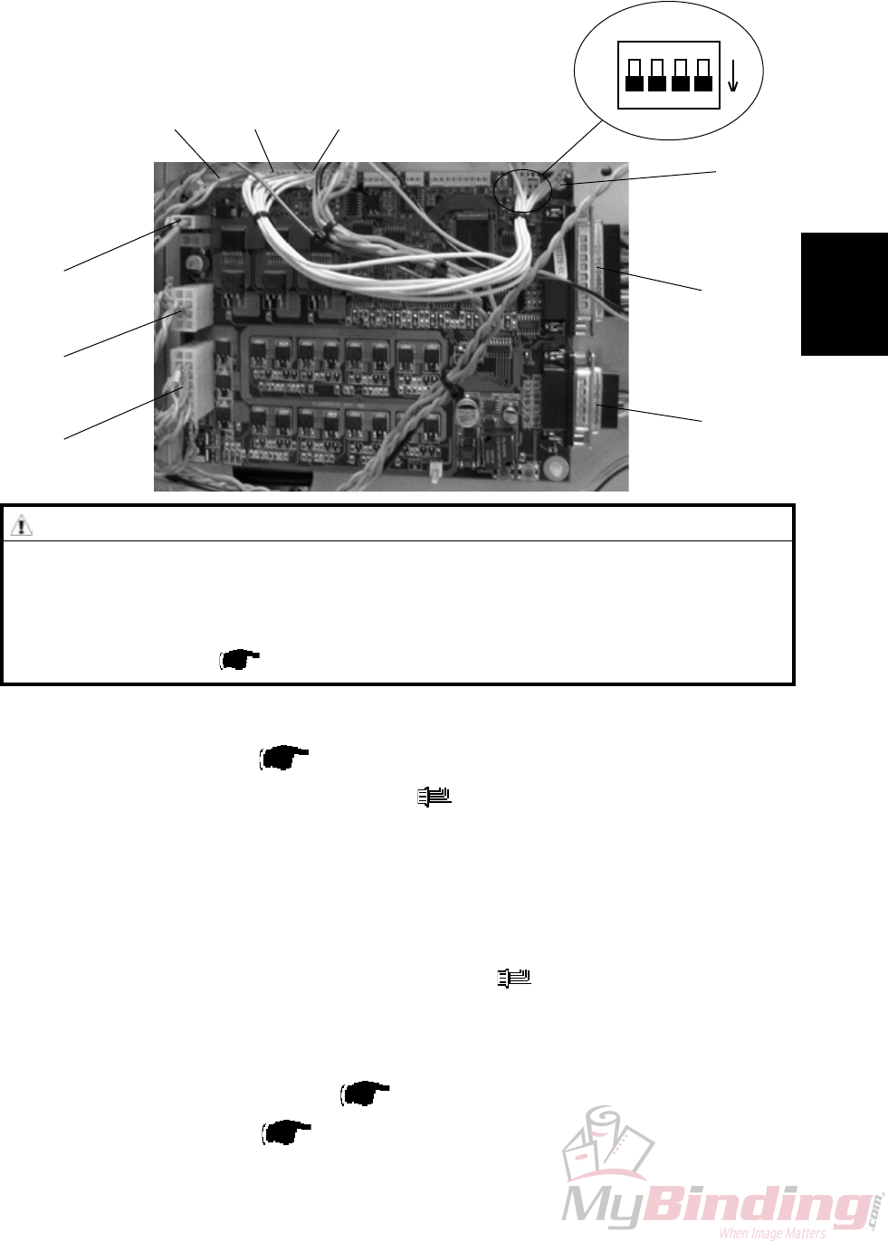
FTR-3-35
PCB
3.3 PCB
3.3.1 MD6DC PCB ”A”
Removal
1. Remove Rear cover ( 3.1.1 ).
2. Remove all connectors from the PCB ( x8 ).
3. Squeeze the barbs of the four pins [A] and lift out the PCB.
Replacement
1. Position the PCB on the pins [A] and snap it in place.
2. Connect all plugs to PCB according to picture ( x8 ).
3. Make sure all DIP-switches are set to OFF according to picture.
NOTE: Make sure replacement PCB has matched software with the system
refering to the latest Technical Bulletin.
Download software if needed ( Service Manual BM 2000 5.2 ).
4. Reinstall Rear cover ( 3.1.1 ).
ON
CAUTION
ESD Hazard! ESD (Electrostatic Discharge) can cause software crashes, data and/or com-
munications problems. Failure to use proper ESD procedures will cause damage to elec-
tronic components (example: PCBs). ESD problems can be minimized by maintaining all
machine ground connections, ensuring the proper handling of circuit boards/ sensors
- Use ESD protection when working near PCBs. Failure to use ESD protection is likely to
result in a PCB failure ( Service Manual BM 2000 3.1 ).
A.P6A.P7A.P4
A.P12
A.P3
A.P2
A.P13
A.P14
[A]

Page intentionally blank

Trouble-
shooting
FTR-4-1
20 September 2006, Rev 0.01
4. TROUBLESHOOTING
4.1 FAULT CODE DESCRIPTIONS
Fault Item Fault description Page
code No. No.
TR-001 TR-M1 Transport motor No displacement pulses ........................................ TR-4-2
TR-002 TR-M1/M2 Transport motor and Trim knife motor Cycle time out .................... TR-4-3
TR-003 TR-M1 Transport motor Short circuit ............................................................ TR-4-4
TR-004 TR-M1 Transport motor Open circuit ............................................................ TR-4-4
TR-005 TR-M2 Trim knife motor Short circuit ........................................................... TR-4-4
TR-006 TR-M2 Trim knife motor Open circuit ............................................................ TR-4-5
TR-007 TR-M3 Stop gate motor Cycle time out ......................................................... TR-4-5
TR-008 TR-M3 Stop gate motor Short circuit ............................................................ TR-4-6
TR-009 TR-M3 Stop gate motor Open circuit ............................................................ TR-4-6
TR-010 TR-M4 Stop gate positioning motor No displacement pulses .................... TR-4-6
TR-011 TR-M4 Stop gate positioning motor Cycle time out .................................... TR-4-7
TR-012 TR-M4 Stop gate positioning motor Short circuit ........................................ TR-4-7
TR-013 TR-M4 Stop gate positioning motor Open circuit ........................................ TR-4-8
TR-014 TR-M5/M6 Blower motor(s) Open circuit ............................................................ TR-4-8
TR-015 TR-Q13 Infeed sensor is Faulty ....................................................................... TR-4-8
TR-016 TR-S2/S3 Control switch infeed or out feed Faulty .......................................... TR-4-9
TR-017 TR-Q6 Outfeed sensor Trimmer is Faulty ..................................................... TR-4-9
TR-018 TR-Q8 Trim bin full sensor is Faulty ........................................................... TR-4-10
TR-150 36V Input low .................................................................................... TR-4-10
TR-151 36V Input high ................................................................................... TR-4-10
TR-152 TR-S9/S10 Interlock switch faulty .......................................................................TR-4-11
TR-201 TR-Q13 Infeed sensor was Not blocked within timeout ...............................TR-4-11
TR-202 TR-Q13 Infeed sensor was Blocked exceeding timeout ..............................TR-4-11
TR-203 TR-Q6 Outfeed sensor Trimmer was Not blocked within timeout ........... TR-4-12
TR-204 TR-Q6 Outfeed sensor Trimmer was Blocked exceeding timeout ........... TR-4-12
TR-205 TR-S2/S3 Infeed shaft or Outfeed compressing bracket
not in lower position ......................................................................... TR-4-12
TR-401 Trim bin full ....................................................................................... TR-4-12
TR-501 Trim bin full ....................................................................................... TR-4-12
TR-502 Trimmer fan missing ......................................................................... TR-4-13
FAULT CODE DESCRIPTIONS

FTR-4-2
20 September 2006, Rev 0.01
TR-001
Fault Code TR-001, indicates that the Transport motor (TR-M1) does not receive any displacement
pulses.
Initial Actions
Check fuse F2 on Transformer.
Make sure that the Transport belt sensor (TR-Q4) is installed correctly ( TR 3.2.5).
Procedure
Enter the Service mode and select Transport motor (TR-M1) in check motors. Does the encoder run properly, Parts catalog
page 13, Item 17?
Y N
1. Check transmission ( 3.2.17).
2. Replace motor TR-M1.
1. Replace sensor TR-Q4.
2. Disconnect plug B.P14 from PCB “A”. Measure between J14-13 and J14-15? (5V and ground). The voltage is
approximately 5 VDC?
Y N
Replace PCB “A”.
Disconnect plug from sensor TR-Q4. Check wires for Continuity / Short circuit from the white wire Q4 to B.P14-14. Is there
Continuity and no Short circuit?
Y N
Replace Wire Harness
Connect plug B.P14 to PCB “A”. Measure between the red wire Q4 and the black wire Q4 (5V and ground). The voltage is
approximately 5 VDC?
Y N
Replace wire Harness.
Replace PCB “A”.
FAULT CODE DESCRIPTIONS

Trouble-
shooting
FTR-4-3
20 September 2006, Rev 0.01
TR-002
Fault Code TR-002, indicates that either the Transport motor (TR-M1) or the Trim Knife motor
(TR-M2) had a Cycle time out.
Initial Actions
Check fuse F2 on Transformer.
Make sure that the Trimmer knife home position sensor (TR-Q5) is installed correctly.
Procedure
Enter the Service mode and select Trimmer knife home position sensor (TR-Q5) in check sensors. The Trimmer knife home
position sensor indicates :1 when the sensor is blocked, and :0 when the sensor is unblocked?
Y N
1. Replace sensor TR-Q5.
2. Disconnect plug B.P13 from PCB “A”. Measure between J13-23 and J13-25 (5V and ground). The voltage is
approximately 5 VDC?
Y N
Replace PCB “A”.
Disconnect plug from sensor TR-Q5. Check wires for Continuity / Short circuit from the white wire Q5 to
B.P13-24. Is there Continuity and no Short circuit?
Y N
Replace wire Harness.
Connect plug B.P13 to PCB “A”. Measure between the red wire Q5 and the black wire Q5 (5V and ground). The
voltage is approximately 5 VDC?
Y N
Replace wire Harness.
Replace PCB “A”.
Enter the Service mode and select Transport motor (TR-M1) and Trim Knife motor (TR-M2) in check motors. Both motors
energizes?
Y N
Disconnect the motor plug M1 to Transport / Knife motor (TR-M1). Enter the Service mode and start Transport motor
(TR-M1) in check motors. Measure between the orange wire M1 and the violet wire M1 (PWM 36V and ground).
The voltage is approximately 22 VDC?
Y N
Disconnect plug B.P3 from PCB “A”. Measure between J3-2 and J3-3 (PWM 36 and ground). The
voltage is approximately 22 VDC?
Y N
Replace PCB “A”.
Replace wire Harness.
Disconnect the motor plug M2 to Trim Knife motor (TR-M2). Enter the Service mode and start Trim Knife motor
(TR-M2) in check motors. Measure between the orange wire M2 and the violet M2 (PWM 36 and ground). The
voltage is approximately 28 VDC?
Y N
Disconnect plug B.P3 from PCB “A”. Measure between J3-6 and J3-7 (PWM 36 and ground). The
voltage is approximately 28 VDC?
Y N
Replace PCB “A”.
Replace wire Harness.
1. Make sure that nothing interferes with the mechanical movement.
2. Lubricate where needed.
1. Make sure that nothing interferes with the mechanical movement.
2. Lubricate where needed.
FAULT CODE DESCRIPTIONS

FTR-4-4
20 September 2006, Rev 0.01
TR-004
Fault Code TR-004, indicates that the Transport motor (TR-M1) has a Open circuit.
Initial Actions
Check fuse F2 on Transformer.
Procedure
Disconnect the motor plug M1. Enter Service mode and start Transport motor (TR-M1) in check motors. Measure between the
orange wire M1 and the violet wire M1 (PWM 36 and ground). The voltage is approximately 22 VDC?
Y N
Disconnect plug B.P3 from PCB “A”. Measure between J3-2 and J3-3 (PWM 36 and ground). The voltage is
approximately 22 VDC?
Y N
Replace PCB “A”.
Replace wire Harness.
Replace motor TR-M1.
TR-003
Fault Code TR-003, indicates that the Transport motor (TR-M1) has a Short circuit.
Initial Actions
Check fuse F2 on Transformer.
Procedure
Disconnect the motor plug M1. Run the Diagnostics again. Fault code TR-004 (Open circuit) is displayed?
Y N
Disconnect plug B.P3 from PCB “A”. Check wires for Short circuit across leads the orange wire M1 to B.P3-3
(violet) and the violet wire M1 to B.P3-2 (orange). Is there Short circuit?
Y N
Replace PCB “A”.
Replace wire Harness.
Replace motor TR-M1.
TR-005
Fault Code TR-005, indicates that the Trim knife motor (TR-M2) has a Short circuit.
Initial Actions
Check fuse F2 on Transformer.
Procedure
Disconnect the motor plug M2. Run the Diagnostics again. Fault code TR-006 (Open circuit) is displayed?
Y N
Disconnect plug B.P3 from PCB “A”. Check wires for Short circuit across leads the orange wire M2 to B.P3-6
(violet) and the violet wire M2 to B.P3-7 (orange). Is there Short circuit?
Y N
Replace PCB “A”.
Replace wire Harness.
Replace motor TR-M2.
FAULT CODE DESCRIPTIONS

Trouble-
shooting
FTR-4-5
20 September 2006, Rev 0.01
TR-006
Fault Code TR-006, indicates that the Trim knife motor (TR-M2) has a Open circuit.
Initial Actions
Check fuse F2 on Transformer.
Procedure
Disconnect the motor plug M2. Enter Service mode and start Trim knife motor (TR-M2) in check motors. Measure between the
orange wire M2 and the violet wire M2 (PWM 36 and ground). The voltage is approximately 22 VDC?
Y N
Disconnect plug B.P3 from PCB “A”. Measure between J3-6 and J3-7 (PWM 36 and ground). The voltage is
approximately 22 VDC?
Y N
Replace PCB “A”.
Replace wire Harness.
Replace motor TR-M2.
TR-007
Fault Code TR-007, indicates that the Stop gate motor (TR-M3) had a Cycle time out.
Initial Actions
Check fuse F2 on Transformer.
Enter the Service mode and select Stop gate motor (TR-M3) in check motors.
Make sure that the Paper stop gate home position sensor (TR-Q7) is installed correctly.
Procedure
Enter the Service mode and select Paper stop gate home position sensor (TR-Q7) in check sensors. The Paper stop gate
home position sensor indicates :1 when the sensor is blocked, and :0 when the sensor is unblocked?
Y N
1. Replace sensor TR-Q7.
2. Disconnect plug B.P13 from PCB “A”. Measure between J13-7 and J13-9 (5V and ground). The voltage is
approximately 5 VDC?
Y N
Replace PCB “A”.
Disconnect plug from sensor TR-Q7. Check wires for Continuity / Short circuit from the white wire Q7 to
B:P13-8. Is there Continuity and no Short circuit?
Y N
Replace wire Harness.
Connect plug B.P13 to PCB “A”. Measure between the red wire Q7 and the black wire Q7 (5V and ground). The
voltage is approximately 5 VDC?
Y N
Replace wire Harness.
Replace PCB “A”.
Are you able to move the Stop gate up and down without it interfering with anything?
Y N
Make sure that the Stop gate does not interferes with the “Deck plate”. Adjust if necessary ( TR 3.2.10).
1. Check the allen screw on the “cam” to TR-M3.
2. Replace motor TR-M3.
FAULT CODE DESCRIPTIONS

FTR-4-6
20 September 2006, Rev 0.01
TR-010
Fault Code TR-010, indicates that the Length adjustment motor (TR-M4) do not receive any displace-
ment pulses.
Initial Actions
Check fuse F2 on Transformer.
Enter the Service mode and select Length adjustment motor (TR-M4) in check motors.
Procedure
Disconnect the sensor plug Q12 to motor M4. Measure between the red wire Q12 and the black wire Q12 (5V and Signal
ground). The voltage is approximately 5 VDC?
Y N
Disconnect plug B.P14 from PCB “A”. Measure between the J14-3 and J14-5 (5V and Signal ground). The volt
age is approximately 5 VDC.
Y N
Replace PCB “A”.
Replace wire harness.
Disconnect plug B.P14 from PCB “A”. Check wires for Continuity / Short circuit from the grey wire Q12 to B.P14-7, the white wire
Q12 to B.P14-4, the black wire Q12 to B.P14-3, the red wire Q12 to B.P14-5. Is there Continuity and no Short circuit?
Y N
Replace wire harness.
1. Replace motor TR-M4.
2. Replace PCB “A”.
TR-009
Fault Code TR-009, indicates that the Stop gate motor (TR-M3) has a Open circuit.
Initial Actions
Check fuse F2 on Transformer.
Procedure
Disconnect the motor plug M3. Enter Service mode and start Stop gate motor (TR-M3) in check motors. Measure between the
orange wire M3 and the violet wire M3 (PWM 36V and ground). The voltage is approximately 36 VDC?
Y N
Disconnect plug B.P2 from PCB “A”. Measure between J2-4 and J2-11 (PWM 36V and ground). The voltage is
approximately 36 VDC?
Y N
Replace PCB “A”.
Replace wire Harness.
Replace motor TR-M3.
TR-008
Fault Code TR-008, indicates that the Stop gate motor (TR-M3) has a Short circuit.
Initial Actions
Check fuse F2 on Transformer.
Procedure
Disconnect the motor plug M3. Run the Diagnostics again. Fault code TR-009 (Open circuit) is displayed?
Y N
Disconnect plug B.P2 from PCB “A”. Check wires for Short circuit across leads the orange wire M3 to B.P2-11
(violet) and the violet wire M3 to B.P2-4 (orange). Is there Short circuit?
Y N
Replace PCB “A”.
Replace wire Harness.
Replace motor TR-M3.
FAULT CODE DESCRIPTIONS

Trouble-
shooting
FTR-4-7
20 September 2006, Rev 0.01
TR-011
Fault Code TR-011, indicates that the Length adjustment motor (TR-M4) had a Cycle time out.
Initial Actions
Check fuse F2 on Transformer.
Enter the Service mode and select Length adjustment motor (TR-M4) in check motors.
Make sure that the Length adjustment home position switch (TR-Q131) is installed correctly.
Procedure
Enter the Service mode and select Length adjustment home position switch (TR-Q131) in check switches. The Length adjust-
ment home position switch indicates :1 activated, and :0 deactivated?
Y N
Disconnect plug B.P13 from PCB “A”. Measure between J13-2 and J13-3 (5V and ground). The voltage is
approximately 5 VDC?
Y N
Replace PCB “A”.
Connect plug B.P13 to PCB “A”. Measure between the white wire Q131 and the black wire Q131 (5V and ground).
The voltage is approximately 5 VDC?
Y N
Replace wire Harness.
1. Replace switch TR-Q131
2. Replace PCB “A.
Enter the Service mode and select Length adjustment motor (TR-M4) in check motors. The motor energizes?
Y N
Replace motor TR-M4.
2. Check the allen screw on the “cam” to the “Stop gate push rod”.
1. Lubricate were needed.
FAULT CODE DESCRIPTIONS
TR-012
Fault Code TR-012, indicates that the Length adjustment motor (TR-M4) has a Short circuit.
Initial Actions
Check fuse F2 on Transformer.
Procedure
Disconnect the motor plug M4. Run the Diagnostics again. Fault code TR-013 (Open circuit) is displayed?
Y N
Disconnect plug B.P2 from PCB “A”. Check wires for Short circuit across leads the orange wire M4 to
B.P2-9 (violet) and the violet wire M4 to B.P2-2 (orange). Is there Short circuit?
Y N
Replace PCB “A”.
Replace wire Harness.
Replace motor TR-M4.

FTR-4-8
20 September 2006, Rev 0.01
TR-013
Fault Code TR-013, indicates that the Length adjustment motor (TR-M4) has an Open circuit.
Initial Actions
Check fuse F2 on Transformer.
Procedure
Disconnect the motor plug M4. Enter Service mode and start Length adjustment motor (TR-M4) in check motors. Measure
between the orange wire M4 and the violet wire M4 (PWM 36V and ground). The voltage is approximately 36 VDC?
Y N
Disconnect plug B.P2 from PCB “A”. Measure between J2-2 and J2-9 (PWM 36V and ground). The voltage is
approximately 36 VDC?
Y N
Replace PCB “A”.
Replace wire Harness.
Replace motor TR-M4.
FAULT CODE DESCRIPTIONS
TR-015
Fault Code TR-015, indicates that the Infeed sensor (TR-Q13) is faulty.
Procedure
Enter the Service mode and select Infeed sensor (TR-Q13) in check sensors. The Infeed sensor indicates :1 activated,
and :0 deactivated?
Y N
Disconnect the connector to sensor Q13. Measure between the wires to sensor Q13 (5V and
ground). The voltage is approximately 5 VDC?
Y N
1. Replace PCB “A”.
2. Replace wire harness.
Replace Infeed sensor (TR-Q13).
Replace PCB “A”.
TR-014
Fault Code TR-014, indicates that the Blowers (TR-M5/M6) have an Open circuit.
Initial Actions
Check fuse F2 on Transformer.
Check placement of blowers.
Procedure
Disconnect the blowers. Enter Service mode and start blowers (TR-M5/M6) in check motors. Measure between the orange
wire M5/M6 and the violet wire M5/M6 (24V and ground). The voltage is approximately 24 VDC?
Y N
Replace PCB.
Replace blowers TR-M5/M6.

Trouble-
shooting
FTR-4-9
20 September 2006, Rev 0.01
FAULT CODE DESCRIPTIONS
TR-017
Fault Code TR-017, indicates that the Outfeed sensor Trimmer (TR-Q6) is faulty.
Initial Actions
Make sure that the Outfeed sensor Trimmer (TR-Q6) is installed correctly.
Procedure
1. Replace sensor TR-Q6.
2. Disconnect plug B.P13 from PCB “A”. Measure between J13-4 and J13-6 (5V and ground). The voltage is
approximately 5 VDC?
Y N
Replace PCB “A”.
Disconnect plug from sensor TR-Q6. Check wires for Continuity / Short circuit from, the white wire Q6 to
B.P13-5. Is there Continuity and no Short circuit?
Y N
Replace wire Harness.
Connect plug B.P13 to PCB “A”. Measure between the red wire Q6 and the black wire Q6 (5V and ground). The voltage is
approximately 5 VDC?
Y N
Replace wire Harness.
Replace PCB “A”.
TR-016
Fault Code TR-016, indicates that the Control switch infeed (TR-S2) or Control switch outfeed (TR-
S3) is faulty.
Initial Actions
Make sure that the Infeed shaft and the Outfeed compressing bracket is in it’s lower position.
Procedure
Enter the Service mode and select Infeed switch (TR-S2/S3) in check switches. The Infeed switch indicates D:1 activated,
and D:0 deactivated?
Y N
Disconnect the two connectors to switch S2/S3. Measure between the two connectors to switch S2/S3 (5V and
ground). The voltage is approximately 5 VDC?
Y N
Replace PCB “A”.
Replace switch S2/S3.
Replace PCB “A”.

FTR-4-10
20 September 2006, Rev 0.01
FAULT CODE DESCRIPTIONS
TR-150 / 151
Fault Code TR-150, indicates that the Unreg is low/high.
Procedure
Measure between D.P14-1 and D.P14-2in the BM 2000. The voltage is approximately 36V?
Y N
Replace the BM 2000 Interlock PCB “D”.
Measure between D.P14-7 and D.P14-8 in the BM 2000. The voltage is approximately 36V?
Y N
Replace the BM 2000 Interlock PCB “D”.
Power OFF the Booklet Maker. Remove the power cable between the booklet maker and the trimmer. Measure for continuity
in the wires between Pin 1, 2, 7 and 8 on both ends of the cable. Is there continuity between all cables?
Y N
Replace the power cable between the BM 2000 and FTR 2000.
Power ON the Booklet Maker. Measure between A.J12-1 and A.J12-2 in the FTR 2000. The voltage is approximately
36V?
Y N
Replace the FTR 2000 wire harness.
Replace PCB “A”.
TR-018
Fault Code TR-018, indicates that the Trim bin full sensor (TR-Q8) is faulty.
Initial Actions
Make sure that the Trim bin full sensor (TR-Q8) is installed correctly.
Procedure
1. Replace sensor TR-Q8.
2. Disconnect plug B.P13 from PCB “A”. Measure between J13-10 and J13-12 (5V and ground). The voltage is
approximately 5 VDC?
Y N
Replace PCB “A”.
Disconnect plug from sensor TR-Q8. Check wires for Continuity / Short circuit from, the white wire Q8 to
B.P13-11. Is there Continuity and no Short circuit?
Y N
Replace wire Harness.
Connect plug B.P13 to PCB “A”. Measure between the red wire Q8 and the black wire Q8 (5V and ground). The voltage is
approximately 5 VDC?
Y N
Replace wire Harness.
Replace PCB “A”.

Trouble-
shooting
FTR-4-11
20 September 2006, Rev 0.01
TR-201
Fault Code TR-201, indicates that during Run, the Infeed sensor (TR-Q13), was not blocked within
timeout.
Initial Actions
Check fuse F2 on Transformer.
Make sure that the Infeed sensor (TR-Q13) is installed correctly.
Procedure
Enter the Service mode and select Infeed sensor (TR-Q13) in check sensors. Activate, then deactivate, the TR-Q13. The Infeed
sensor (TR-Q13) indicates :1 when the sensor is activated and :0 when the sensor is deactivated.
Y N
Go to TR-016 fault code.
1. Make sure that the Exit guide bracket is installed as high as possible.
2. Make sure that nothing interferes with the paper path.
FAULT CODE DESCRIPTIONS
TR-152
Fault Code TR-151, indicates that the Interlock switch is faulty.
Initial Actions
Check fuse F2 on Transformer.
Enter the Service mode and check the Trimmer voltmeter.
Power ON and Power OFF the Trimmer (make sure that the Top cover interlock, and
the External Interlock Device interlock is interlocked).
Procedure
Measure the Interlock switch S9 and S10, and make sure that they are OK. Are all two switches OK?
Y N
Replace faulty switch.
Measure for continuity between J14-18 and J14-19, between J25-3 and J25-4. Is there continuity in both cables?
Y N
Replace wire harness.
Replace PCB.
TR-202
Fault Code TR-202, indicates that at “initialization” or during Run, the Infeed sensor (TR-Q13), was
blocked exceeding timeout.
Initial Actions
Check fuse F2 on Transformer.
Make sure that the Infeed sensor (TR-Q13) is installed correctly.
Procedure
Enter the Service mode and select Infeed sensor (TR-Q13) in check sensors. Activate, then deactivate, the TR-Q13. The Infeed
sensor (TR-Q13) indicates :1 when the sensor is activated and :0 when the sensor is deactivated.
Y N
Go to TR-016 fault code.
Make sure that nothing interferes with the paper path.

FTR-4-12
20 September 2006, Rev 0.01
FAULT CODE DESCRIPTIONS
TR-204
Fault Code TR-204, indicates that at “initialization” or during Run, the Outfeed sensor Trimmer (TR-
Q6), was blocked exceeding timeout.
Initial Actions
Check fuse F2 on Transformer.
Make sure that the Outfeed sensor Trimmer (TR-Q6) is installed correctly.
Ensure that the Outfeed sensor Trimmer (TR-Q6) is clean.
Procedure
Enter the Service mode and select Outfeed sensor Trimmer (TR-Q6) in check sensors. Block, then unblock, the TR-Q6 with
a sheet of paper. The Outfeed sensor Trimmer (TR-Q6) sensor indicates :1 when the sensor is blocked and :0 when
the sensor is not blocked.
Y N
Go to TR-017 fault code.
Make sure that nothing interferes with the paper path.
TR-401
Fault Code TR-401, indicates that the Trim bin is full, or that the Trim bin full sensor TR-Q8 is faulty.
Procedure
Is there something blocking the Trim bin full sensor TR-Q8?
Y N
Go to TR-018 fault code.
Remove the object and empty the Trim bin.
TR-501
Fault Code TR-501, indicates that the Trim bin is full, or that the Trim bin full sensor TR-Q8 is faulty.
Procedure
Is there something blocking the Trim bin full sensor TR-Q8?
Y N
Go to TR-018 fault code.
Remove the object and empty the Trim bin.
TR-203
Fault Code TR-203, indicates that during Run, the Outfeed sensor trimmer (TR-Q6), was not blocked
within timeout.
Initial Actions
Check fuse F2 on Transformer.
Make sure that the Outfeed sensor trimmer (TR-Q6) is installed correctly.
Ensure that the Outfeed sensor trimmer (TR-Q6) is clean.
Procedure
Enter the Service mode and select Outfeed sensor trimmer (TR-Q6) in check sensors. Block, then unblock, the TR-Q6 with a
sheet of paper. The Outfeed sensor trimmer (TR-Q6) sensor indicates :1 when the sensor is blocked and :0 when the
sensor is not blocked.
Y N
Go to TR-017 fault code.
Make sure that nothing interferes with the paper path.
TR-205
Fault Code TR-205, indicates that the Infeed shaft or the Outfeed compressing bracket not is in it’s
lower position or that control switch S2 or S3 is faulty.
Procedure
Is the Infeed shaft or the Outfeed compressing bracket lifted from it’s lower position?
Y N
Go to TR-016 fault code.
Lift Infeed/outfeed latch and make sure that the Infeed shaft and the Outfeed compressing bracket is in it’s lower position.

Trouble-
shooting
FTR-4-13
20 September 2006, Rev 0.01
TR-502
Fault Code TR-502, indicates that the blowers (TR-M5/M6) do not respond.
Initial Actions
Check placement of blowers.
Make sure blowers are installed correctly.
Procedure
Enter the Service mode and select blowers Trimmer (TR-M5/M6) in check motors. Do the blowers work?
Y N
Go to TR-014 fault code.
Replace PCB.

FTR-4-14
Page intentionally blank

Service
Tables
FTR-5-1
20 September 2006, Rev 0.01
5 SERVICE TABLES
5.1 SERVICE TABLES
Trimmer SERVICE TABLES is located in the Booklet Maker BM 2000 Service
Manual.

Page intentionally blank

Detailed
description
FTR-6-1
20 September 2006, Rev 0.01
ELECTRICAL COMPONENT LIST
6. DETAILED SECTION DESCRIPTIONS
6.1 ELECTRICAL COMPONENT LIST
Page
FTR-M1 Transport motor .........................................................................FTR-6-3 / FTR-6-4
FTR-M2 Trim knife motor .........................................................................FTR-6-3 / FTR-6-4
FTR-M3 Stop gate motor ......................................................................................... FTR-6-5
FTR-M4 Length adjustment motor ......................................................................... FTR-6-5
FTR-M5/M6 Blower motor .............................................................................................. FTR-6-3
FTR-Q13 Infeed sensor ............................................................................................. FTR-6-3
FTR-S2 Control switch infeed ................................................................................ FTR-6-2
FTR-S3 Control switch outfeed .............................................................................. FTR-6-2
FTR-Q4 Transport belt sensor ................................................................................ FTR-6-2
FTR-Q5 Trim knife home position sensor ............................................................. FTR-6-2
FTR-Q6 Outfeed sensor .......................................................................................... FTR-6-2
FTR-Q7 Paper stop gate home position sensor ................................................... FTR-6-5
FTR-Q8 Trim bin full sensor .................................................................................... FTR-6-3
FTR-S9 Interlock switch .......................................................................................... FTR-6-3
FTR-Q130 Interlock magnet ........................................................................................ FTR-6-3
FTR-S11 Length adjustment home position switch ............................................... FTR-6-5
FTR-Q12 Length adj. motor sensor (loc. on mot M4) ............................................. FTR-6-5
PCB MD6DC PCB ”A” ........................................................................................ FTR-6-2
Stacker Receptacle............................................................................................................ FTR-6-2
Communication Booklet Maker BM2000 ......................................................................... FTR-6-2
Power supply Trimmer FTR2000 ...................................................................................... FTR-6-2
Terminator / Communication Square Fold SQF2000 ...................................................... FTR-6-2
Counter ..................................................................................................................... FTR-6-2
Safety block for knife ........................................................................................................ FTR-6-2
FTR-6-2
20 September 2006, Rev 0.01
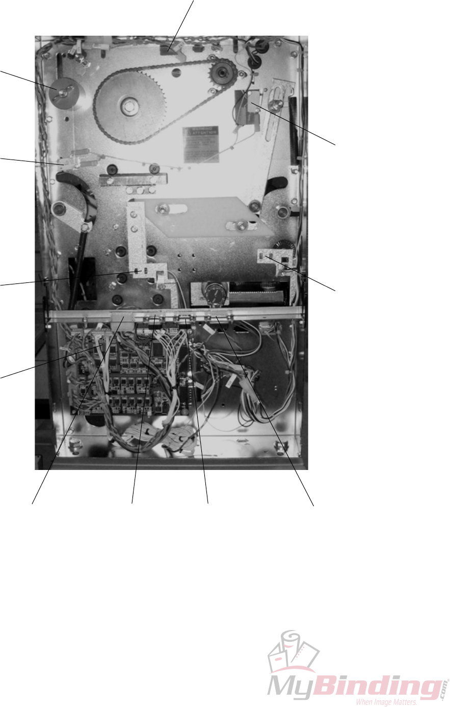
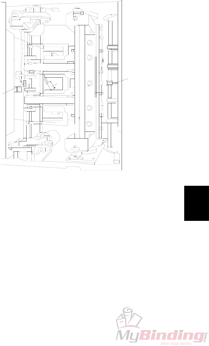
6.1.1 REAR VIEW
FTR-S2 FTR-S3
FTR-Q4
FTR-Q5
MD6DC
PCB “A”
Safety
block
Power sup-
ply trimmer Stacker recep-
tacle
COM BM2000 Terminator /
COM SQF2000
ELECTRICAL COMPONENT LIST
Counter
Detailed
description
FTR-6-3
20 September 2006, Rev 0.01
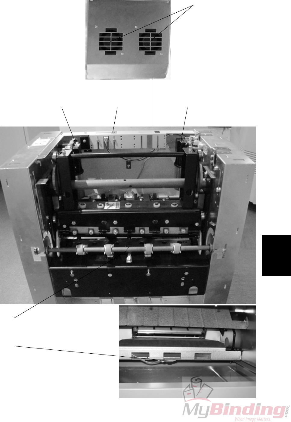
6.1.2 INFEED VIEW
FTR-M1 FTR-M2
FTR-Q13
FTR-Q8
Interlock Switch
FTR-S9 / Q130
FTR-M5 / M6
ELECTRICAL COMPONENT LIST
FTR-6-4
20 September 2006, Rev 0.01
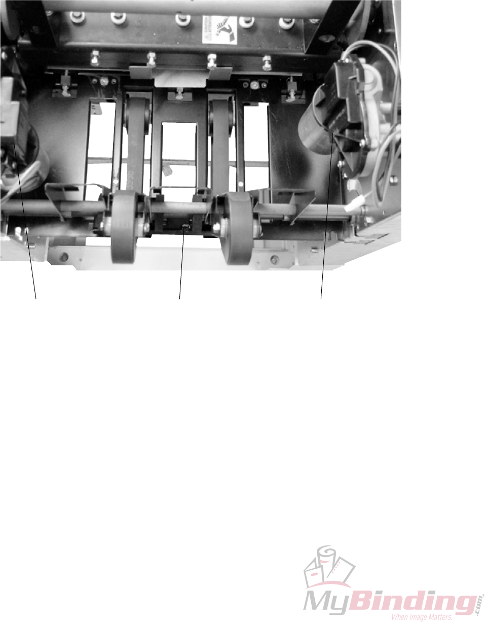
6.1.3 OUTFEED VIEW
FTR-Q6FTR-M2 FTR-M1
ELECTRICAL COMPONENT LIST
Detailed
description
FTR-6-5
20 September 2006, Rev 0.01
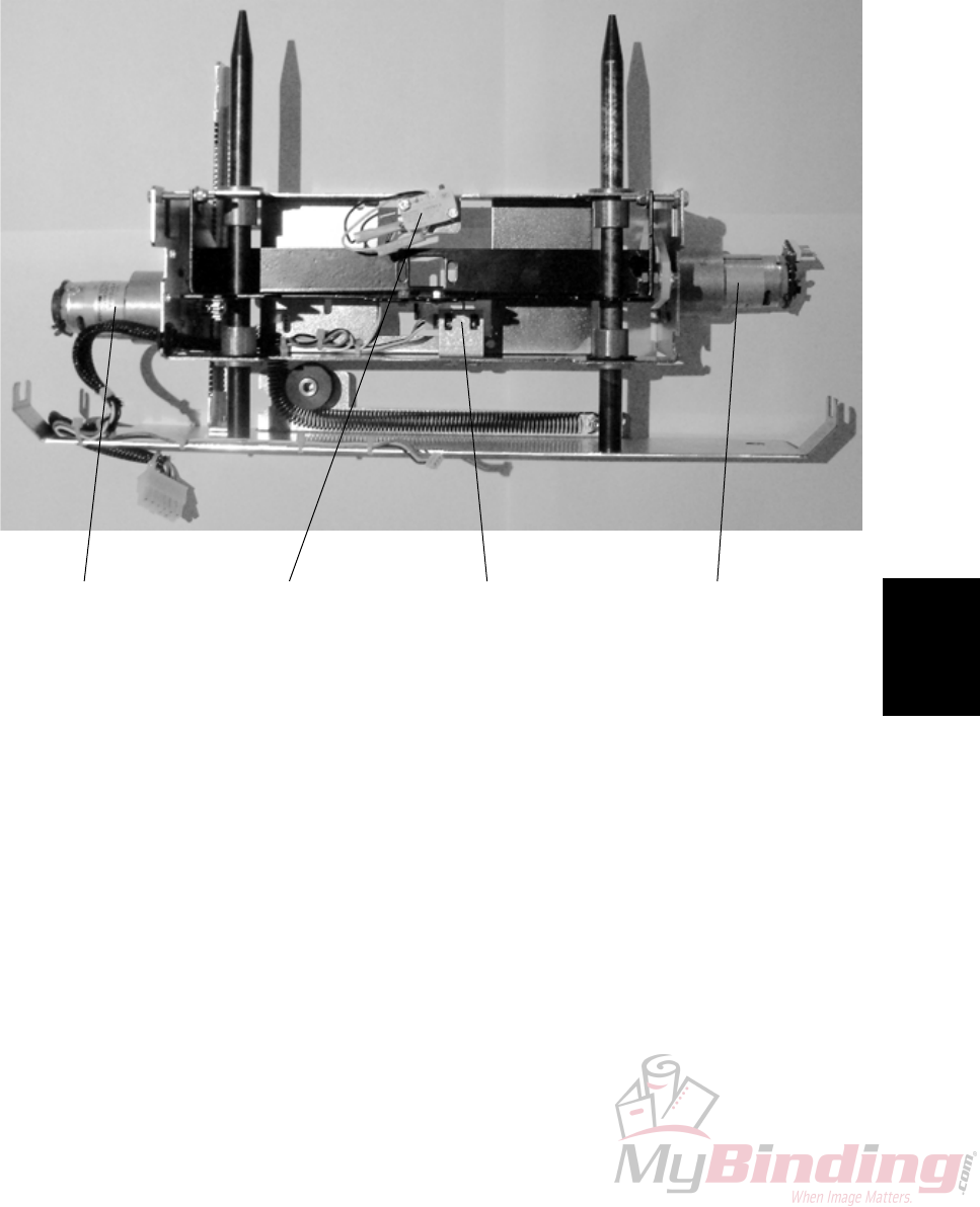
6.1.4 STOP CARRIAGE VIEW
FTR-M3FTR-M4 /
FTR-Q12 FTR-Q7FTR-S11
ELECTRICAL COMPONENT LIST

Page intentionally blank
Detailed
description
FTR-6-7
20 September 2006, Rev 0.01
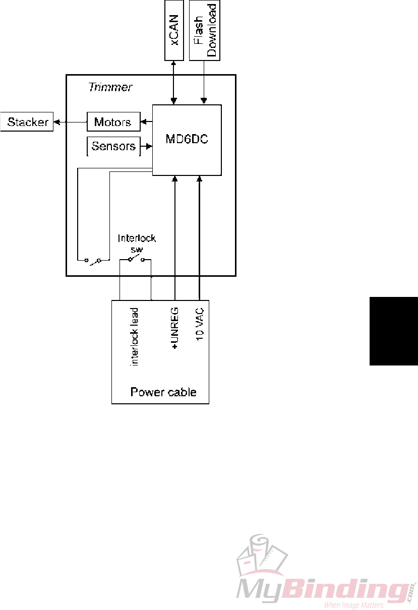
6.2 BOARD STRUCTURE
6.2.1 BLOCK DIAGRAM
Interlock
magnet
FTR-6-8
20 September 2006, Rev 0.01
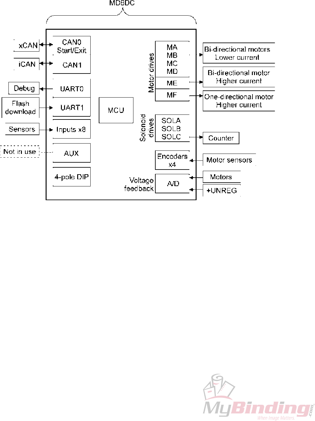
6.2.2 CONTROLLER MD6DC
The motor drives:
MA-MD are for bi-directional motors with lower current
ME is for bi-directional motor with higher current.
MF is for one-directional motor with higher current.
As the FTR 2000 does not have any solenoids, one of the solenoid drives is used
for the electro-mechanical counter.

Detailed
description
FTR-6-9
20 September 2006, Rev 0.01
6.2.2 CONTROLLER MD6DC, CONTINUES
FTR-M2 FTR-M1 FTR-M4
FTR-M3 ST-M1Set counter
FTR-M5
&
FTR-M6

Page intentionally blank
Detailed
description
FTR-6-11
20 September 2006, Rev 0.01
M1
M2
Q6
Q13
S11
6.3 TRIMMING PROCESS
6.3.1 PRINCIPLE OF OPERATION
TRIMMING PROCESS
Trimming
Booklet maker sends a start signal, stop gate motor (FTR-M3) moves the stop
gate to up position and is stopped when the stop gate home position sensor (FTR-
Q7) activates. The transport motor (FTR-M1) starts and transports the booklet
into the machine. The infeed sensor (FTR-Q13) is activated by the booklet. The
booklet passes and deactivates the infeed sensor (FTR-Q13). When the booklet
hits the stop gate, the transport motor (FTR-M1) stops. The timing is controlled by
transport motor sensor (FTR-Q4) and set by the paper size.
Trim knife motor (FTR-M2) starts moving the knife down. After a while when the
knife is about to cut the sheets, transport motor (FTR-M1) is triggered by knife
position sensor (FTR-Q5) to reverse and helps knife motor (FTR-M2) during the
cutting stroke. About the time when the knife has cut through the sheets, the stop
gate motor (FTR-M3) moves the stop gate down and the transport motor (FTR-M1)
reverses again to transport the set out of the machine. The knife motor completes
its cycle and stops at the trim knife home position sensor (FTR-Q5).
The stacker motor (ST-M1) starts when the outfeed sensor (FTR-Q6) activates and
runs for a short while to separate the booklets on the stacker belt.

FTR-6-12
20 September 2006, Rev 0.01
6.3.2 SIZE ADJUSTMENT
Initialization cycle
Main power is switched on.
Length adjustment motor (FTR-M4) starts. The motor (FTR-M4) moves the stop
gate to the smallest booklet size.
The motor (FTR-M4) stops when length adjustment home position switch (FTR-
S11) is activated.
When the switch(FTR-S11) is activated, a counter for the motor (FTR-M4) starts
and the motor (FTR-M4) reverses.
The motor (FTR-M4) runs until* length adjustment motor sensor (FTR-Q12) has
counted the preset amount of pulses set by the paper size and trim length. The
stop gate is now in correct position corresponding to the paper size and trim length
selected.
Changing paper size
New paper size and or trim length is selected on the UI.
Length adjustment motor (FTR-M4) starts. The motor (FTR-M4) runs in the direc-
tion towards the new paper size. Length adjustment motor sensor (FTR-Q12)
counts pulses from the previous paper size to the new paper size and stops motor
(FTR-M4) when correct amount of pulses are received*. Stop gate is now in cor-
rect position corresponding to the new paper size selected.
If paper jam occurs
If top cover is opened and closed:
Stop gate motor (FTR-M3) moves the stop gate down. Length adjustment motor
(FTR-M4) moves the stop gate to the smallest booklet size.
* Length adjustment motor (TR-M4) actually passes the stop position slightly,
reverses slightly pass the point and reverses again for the last time to stop at the
exact position, to take out any play.
TRIMMING PROCESS

FTR-Spc-1
20 September 2006, Rev 0.01
Specication
SPECIFICATIONS
SPECIFICATIONS
Trimmer SPECIFICATIONS is located in the Booklet Maker BM 2000 Service
Manual.

Page intentionally blank

FTR-Wir-1
20 September 2006, Rev 0.01
Wiring
WIRING
Trimmer
See pocket at rear of manual for wiring diagrams.

Page intentionally blank
