N V Nederlandsche Apparatenfabriek NEDAP MACER1 Reader for 120 kHz and 13.56 MHz cards and also NFC, QR and BT User Manual Report
N. V. Nederlandsche Apparatenfabriek NEDAP Reader for 120 kHz and 13.56 MHz cards and also NFC, QR and BT Report
Contents
- 1. 14_MaceMM_InstallGuide_E CGDMACER1
- 2. 16_MACE Reader MM QR_Nedap_v1.2 CGDMACER1
- 3. 17_Nedap_brochure_MACE LR CGDMACER1
14_MaceMM_InstallGuide_E CGDMACER1
MACE MM (QR)
installation guide
2016
-08-18 | v1.5 | 5285852

MACE | INSTALLATION GUIDE
Content
2/30
CONTENT
1 INTRODUCTION _______________________________________________________ 3
1.1 MACE __________________________________________________________ 3
1.2 NOTES _________________________________________________________ 3
2 INSTALLATION ________________________________________________________ 4
2.1 SAFETY INSTRUCTION ____________________________________________ 4
2.2 MOUNTING INSTRUCTIONS _______________________________________ 4
3 CONNECTIONS ________________________________________________________ 6
3.1 POWER SUPPLY _________________________________________________ 6
3.2 COMMUNICATION _______________________________________________ 6
3.2.1 RS485 ___________________________________________________ 6
3.2.2 USB _____________________________________________________ 7
3.2.3 WIEGAND ________________________________________________ 8
3.2.4 MAGSTRIPE ISO7811/2 ____________________________________ 9
3.3 LED CONTROL _________________________________________________ 10
3.4 TAMPER SWITCH _______________________________________________ 11
3.5 NEDAP ANTENNA INTERFACE _____________________________________ 11
4 READER CONFIGURATION ______________________________________________ 12
4.1 CONFIG SOFTWARE _____________________________________________ 12
4.2 OPTIONS ______________________________________________________ 13
4.2.1 USER MODE _____________________________________________ 13
4.2.2 SEND CONFIG ___________________________________________ 13
4.2.3 READ CONFIG ___________________________________________ 13
4.2.4 SETUP BAUDRATE ________________________________________ 13
4.2.5 RESET CONFIG ___________________________________________ 13
4.3 SETTINGS _____________________________________________________ 14
4.3.1 GENERAL _______________________________________________ 14
4.3.2 LED/BUZZER ____________________________________________ 14
4.4 READER SETTINGS ______________________________________________ 15
4.4.1 BLE ____________________________________________________ 15
4.4.2 NFC ____________________________________________________ 16
4.4.3 QR-CODE _______________________________________________ 17
4.4.4 DESFIRE ________________________________________________ 18
4.4.5 MIFARE _________________________________________________ 19
4.4.6 OTHER ID TYPES _________________________________________ 20
4.5 COMMUNICATION OUTPUT ______________________________________ 21
4.5.1 SERIAL __________________________________________________ 21
4.5.2 WIEGAND/MAGSTRIPE ____________________________________ 22
Unconfigured __________________________________________________ 22
Wiegand ______________________________________________________ 22
Magstripe _____________________________________________________ 24
A TECHNICAL SPECIFICATIONS ___________________________________________ 26
B PART NUMBERS ______________________________________________________ 27
C FCC AND ISED DECLARATIONS __________________________________________ 28
D DISCLAIMER _________________________________________________________ 29
E DOCUMENT REVISION _________________________________________________ 30

MACE | INSTALLATION GUIDE
Introduction
3/30
1 INTRODUCTION
1.1 MACE
MACE is an acronym for Mobile Access Control Entities. MACE is a platform
consisting of readers, apps and a cloud based server that enables the use of
smartphones to identify people.
MACE supports Bluetooth, NFC and QR-codes to identify people using virtual
credentials are stored in a MACE app that is available for iPhone and Android.
MACE can be used in combination with any access control system or any other
system that requires the swift identification of people, like parking management
systems or registration systems.
Please remember to fill out the ‘How to Order Guide’ to prepare your MACE
installation and order virtual MACE credentials that will be read by the MACE
Readers you plan to install.
1.2 NOTES
• MACE is introduced in 2016 and the platform is expected to be subject to
continuous development and improvement. You can expect further
customization options and advanced 3rd party interfacing options to be
available throughout 2016 and 2017.
• If you need assistance or require any option other then found in this guide,
please consult with your Nedap representative.
• There is a lot of variation in performance and characteristics of Bluetooth
and NFC communication across the wide range of phones that are available
today. Please take this into account when planning the commissioning and
configuration of your application.
• The cloud based MACE server distributes the virtual credentials to the
phones of people. And to do that we need something to uniquely identify
the user. Amongst others an e-mail address is used for that.
MACE | INSTALLATION GUIDE
Installation
4/30
2 INSTALLATION
2.1 SAFETY INSTRUCTION
The following safety precautions should be observed during normal use, service and
repair.
• The MACE may only be installed and serviced by qualified service
personnel.
• Disconnect the power supply before (dis)connecting any wires, MACE is NOT
hot-swappable, so when making or changing connections, power must be
switched OFF.
• The cable shield shall be connected with safety ground and the metal case
of the external device(s).
• To be sure of safety, do not modify or add anything to the MACE other than
mentioned in this installation guide or indicated by NEDAP N.V.
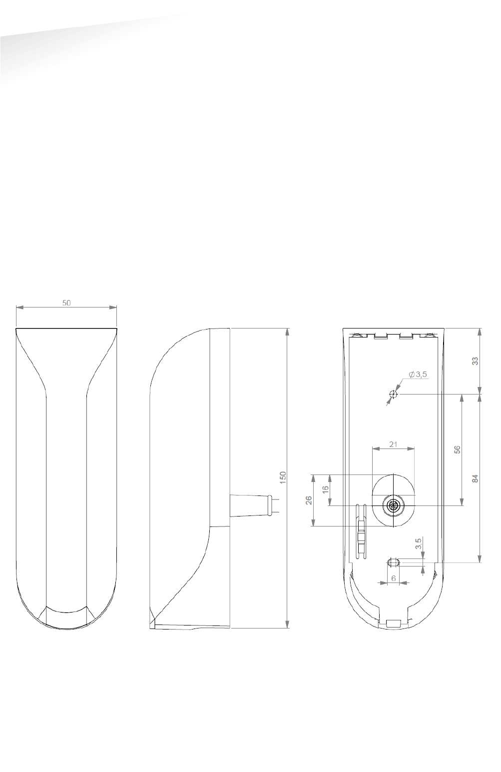
2.2 MOUNTING INSTRUCTIONS
The MACE can be mounted to any surface, including directly to metal. See the
picture below for details about the dimensions.
Figure
1
: MACE dimensions (mm)
MACE | INSTALLATION GUIDE
Installation
5/30
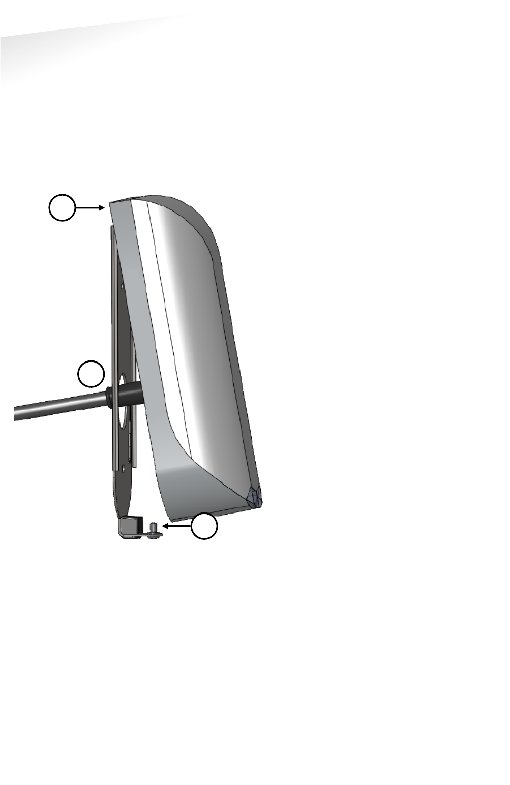
Mount the base-plate on the required location.
Ensure that it is placed correctly covering the cable entry hole. Properly fix the base-
plate into its position using the 2 screws. When mounting on a stone or concrete
wall drill 5mm holes for the plugs. When mounting on wood, drill with 2.5mm.
Install the MACE reader onto the base-plate.
1 Feed the cable through the cable entry hole. Important note: minimum
bending radius 30mm.
2 Attach the top of the MACE onto the base-plate.
3 Fix the assembly using the screw on the bottom.
Figure
2
: MACE installation
1
2
3

MACE | INSTALLATION GUIDE
Connections
6/30
3 CONNECTIONS
The MACE is supplied with a 5 meter (15 feet) shielded cable pigtail with 12 colored
wires.
RED
Power supply 12 - 24VDC.
BLACK
Power supply 0VDC, DC-Ground.
BROWN
RS485 A (-)
GREEN
RS485 B (+)
GRAY
Data-0 / Clock
PINK
Data-1 / Data
YELLOW
Tamper switch (normally closed)
GRY/PNK
Tamper switch (common)
RED/BLU
Led_UL_IN*
WHITE
Led_NA_IN*
PURPLE
Nedap antenna interface. Connect to ANT.
BLUE
Beeper_IN*
SHIELD
Shield
3.1 POWER SUPPLY
The MACE requires DC power supply in the range from 12 – 24V.
Maximum current consumption is 0.4A @ 12VDC, 0.2A @ 24VDC.
Connections:
RED
Power supply 12 - 24VDC.
BLACK
Power supply 0V / DC-ground.
SHIELD
Shield connected to DC-ground.
3.2 COMMUNICATION
3.2.1 RS485
The MACE reader has a RS485 interface for communication with a host system or to
configure the reader settings. RS485 is a 2-wire half-duplex serial communication
interface using balanced lines.
Connections:
BROWN
RS485 A (-) Balanced RX/TX
GREEN
RS485 B (+) Balanced RX/TR
SHIELD
Shield connected to DC-ground.
For details about reader configuration see chapter 4.
Default RS485 communication baud rate is 115200. See chapter 4.2.4.
The RS485 output message format is described in chapter 4.5.1
Note
Cable shield shall
be
connected to the metal
case of the external
device(s). Cable extensions
shall only be made by
means of shielded cable(s).
All shields of the shielded
cable extensions shall be
connected together and to
the metal case of the
external device(s).
Led_UL_IN
, Led_NA_IN and
Beeper_IN are inputs that
are active LOW.
Note:
Extending this connection
beyond the 5 meter pig tail
length shall ONLY be
allowed using shielded
cable.
The minimum voltage at the
end of the fixed shieled
pigtail cable shall be
greater
than 12VDC -10%
The shield shall be
connected to the metal
case of the external device.
Note:
The RS485 interface is
disabled while the USB
interface is in use!
Extending this connection
beyond the 5 meter pig tail
length shall ONLY be
allowed using
shielded
twisted pair cable(2 x 2 x
0.25 mm2) as long as the
total length is shorter than
1200 meters, 6000 feet,
cable capacity < 100
pF/meter.
The second twisted pair
shall be used for the DC
power supply.
The shield shall be
connected to the metal
case
of the external device.

MACE | INSTALLATION GUIDE
Connections
7/30
3.2.2 USB
The MACE reader features an USB interface for service, installation and firmware
upgrade purposes. The Mini-USB connector is located on the bottom of the device
and can only be reached when the bottom screw is opened and the MACE is lifted
away from the base-plate. This ensures that unauthorized modifications to the
reader settings can be detected using the tamper switch.
The USB interface can be used to configure the reader using the MACE config tool
software. See chapter 4.
USB Driver installation
Make sure your computer is connected to the internet. The driver should install
automatically via Windows update when the MACE reader is connected to your PC
via the USB cable. Follow the driver installation wizard. If you do not see the
Windows update pop-up, you can manually install the driver. To manually install,
you need to go to FTDI’s website at www.ftdichip.com/Drivers/VCP.htm and
download the VCP (Virtual Com Port) drivers for your operating system. Drivers for
MacOS and Linux are available as well.
Note
While the shielded USB
cable is connected, the
RS485 interface is disabled!
The maximum shielded
cable length shall be < 2
meter.
MACE | INSTALLATION GUIDE
Connections
8/30
3.2.3 WIEGAND
The Wiegand and Magstripe ISO7811/2 (clock & data) interface share the same
connections. This means that only Wiegand or Magstripe can be used and not both
simulaneously.
Wiegand connections:
GRAY
D0
PINK
D1
BLACK
Ground (0V)
SHIELD
Shield connected to DC-ground.
Message format:
The Wiegand output format is determined by the programming format of the
credential. MACE Wiegand credentials will automatically generate a Wiegand
message. If the credential is not programmed in Wiegand format, you may configure
the message output format as described in chapter 4.5.2.
Make sure to order the correct credential programming format if you want to use the
Wiegand or Magstripe interface. See also the MACE how to order guide (HTOG) for
more information.
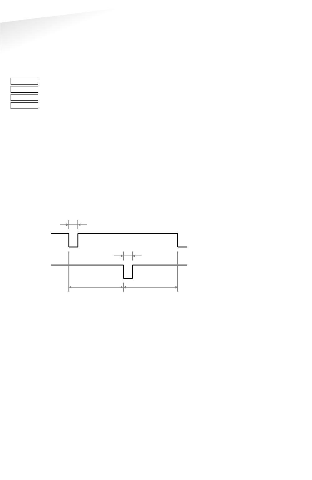
Wiegand Timing
In the figure below the Wiegand protocol timing is specified.
Tpw
5V
0V
D1
5V
0V
D0
Tpi
Tpi
Tpw
Figure 3: Wiegand protocol timing
Timing constants:
Tpi Pulse interval time 1msec
Tpw Pulse width time 50µsec
Note
Extending these
connections beyond the 5
meter pig tail
length shall
ONLY be allowed using
shielded cable (4 x 0.25
mm2) as long as the total
length is shorter th
an 150
meters (500 feet).
The shield shall be
connected to the metal
case of the external device.
MACE | INSTALLATION GUIDE
Connections
9/30
3.2.4 MAGSTRIPE ISO7811/2
The Magstripe ISO78122/2 (clock & data) and Wiegand interface share the same
connections. This means that only Wiegand or Magstripe can be used and not both
simulaneously.
Magstripe connections:
GRAY
CLK
PINK
DAT
BLACK
Ground (0V)
SHIELD
Shield connected to DC-ground.
Message format:
The Magstripe output format is determined by the programming format of the
credential. MACE Magstripe credentials will automatically generate a Magstripe
message. If the credential is not programmed in Magstripe format, you may
configure the message output format as described in chapter 4.5.2.
Make sure to order the correct credential programming format if you want to use the
Wiegand or Magstripe interface. See also the MACE how to order guide (HTOG) for
more information.
Magstripe Timing
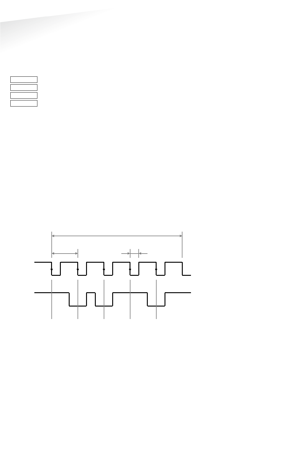
The figure below shows the timing for one magstripe character. Each bit consists out
of one period low (220µsec) and two periods high (440µsec). The Data-signal is valid
and stable on the falling edge of the Clock-signal.
odd parity
msb
lsb
3300µsec
0
1
1
0
1
220µsec
660µsec
5V
0V
CLK
5V
0V
DAT
Figure 4: Magstripe protocol timing one character
Timing constants:
Clock period 660µsec
Clock high 440µsec
Clock low 220µsec
Data pre-amble 16 clock periods
Data post-amble 16 clock periods
Note
Extending these
connections beyond the 5
meter pig tail length shall
ONLY be allowed using
shielded cable (4
x 0.25
mm2) as long as the total
length is shorter th
an 150
meters (500 feet).
The shield shall be
connected to the metal
case of the external device.

MACE | INSTALLATION GUIDE
Connections
10/30
3.3 LED CONTROL
The built-in high intensity LED provides visual feedback that the tag has been read
or authorized. The LED and buzzer can be controlled by the access control system.
Automatic mode:
Default the MACE will automatically control the LED.
During stand-by the LED will be BLUE and upon identification it will be GREEN.
These colors can be changed!
Remote control:
The LED can be controlled remotely by a connected access control system. Digital
inputs will determine the color indicated on the LED. Use MACE config tool to enable
the Remote LED control mode.
RED/BLU
Led_UL_IN*
WHITE
Led_NA_IN*
BLUE
Beeper_IN*
BLACK
Ground
SHIELD
Shield connected to DC-ground.
Note
Extending these
connections beyond the 5
meter pig tail length shall
ONLY be allowed using
shielded cable (4 x 0.25
mm2) as long as the total
length is shorter th
an 150
meters (500 feet).
T
he shield shall be
connected to the metal
case of the external device.

MACE | INSTALLATION GUIDE
Connections
11/30
3.4 TAMPER SWITCH
An internal magnet provides tamper indication when the reader is dismounted. This
contact may be connected to an external alarm system. The contacts are normally
closed when the reader is in place.
Tamper switches of multiple readers can be connected in series.
Connections:
YELLOW
Tamper switch (normally closed)
GRY/PNK
Tamper switch (common)
SHIELD
Shield connected to DC-ground.
Contact ratings:
Max. current 50 mA (0.5 Volt voltage drop)
Max. switching voltage +24 VDC
3.5 NEDAP ANTENNA INTERFACE
The Nedap antenna interface is used to connect the MACE to NEDAP AEOS access
control hardware such as the AP1001. Instead of proximity antenna the MACE can be
connected.
Connections:
PURPLE
Nedap antenna interface. Connect to ANT.
BLACK
Nedap antenna interface. Ground, shield. Connect to ANT GND.
SHIELD
Shield connected to DC-ground.
Note
Extending this connection
beyond the 5 meter pig tail
length shall ONLY be
allowed using shielded
cable (2 x 0.25 mm2) as
long as the total length is
shorter than 150 meters
(500 feet).
The shield shall be
connected to the
metal
case of the external device.
Note
Extending this connection
beyond the 5 meter pig tail
length shall ONLY be
allowed using coaxial cable,
RG58U, as long as the total
length is shorter than 100
meters (350 feet).
The shield shall be
connected to
the metal
case of the external device.
MACE | INSTALLATION GUIDE
Reader configuration
12/30
4 READER CONFIGURATION
The MACE reader can be configured easily using the MaceConfigTool software.
Configuration allows to change:
• General settings.
• Reader settings; what to read and how.
• Communication output settings.
Some settings require expert knowledge. Leave settings unchanged, when their
specific meaning is unclear.
It’s always a good practice to save the configuration into a file for future reference or
when requesting technical assistance from Nedap or its business partners.
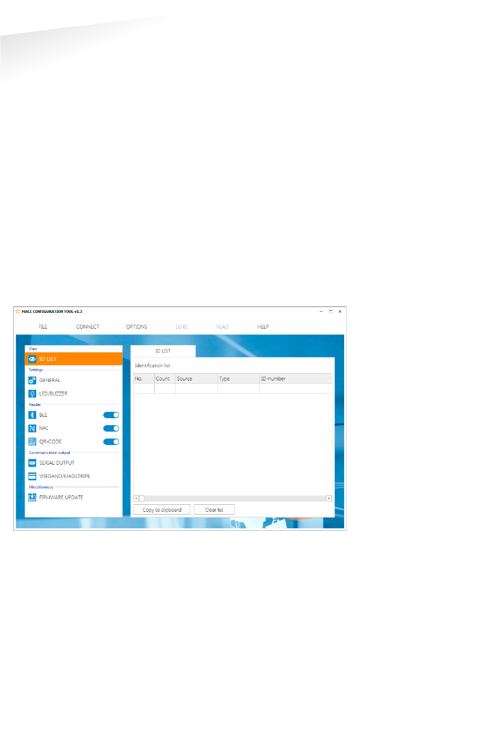
4.1 CONFIG SOFTWARE
The MaceConfigTool software allow to configure all settings for the MACE reader.
The software can interface with the reader using the USB or RS485 interface.
Figure 5: MaceConfigTool software
Start the MaceConfigTool software and click CONNECT.
Select the COM-port and the baud rate and click OK.
Default baud rate is 115200.
When the connection is established, the software checks the MACE firmware
version.
Check the ID List to see what is identified.
Check the Console to see the communication details. For details about the
communication protocol refer to the firmware manual.

MACE | INSTALLATION GUIDE
Reader configuration
13/30
4.2 OPTIONS
The options menu gives access to various Mace reader configuration options.
4.2.1 USER MODE
Select user mode simple or avanced to adjust the user interface.
4.2.2 SEND CONFIG
Send configuration to reader.
This options will send all configuration settings to the reader and saves them into
non-volatile memory of the reader. A message indicates that the configuration was
sent successfully.
4.2.3 READ CONFIG
Read configuration from reader.
This options will read all* configuration settings from the reader.
A message indicates that the configuration was read successfully.
* Security keys and passwords cannot be read from the reader.
4.2.4 SETUP BAUDRATE
Select the serial communication baud rate.
Possible selections are:
1200
2400
9600
19200
38400
57600
115200 (default)
Click OK after changing the baud rate. Upon success the software will show a
message and the baud rate in the software and reader have been changed. The new
baud rate setting in the reader is saved to non-volatile memory.
Note that when using a separate interface converter, it may be required to update
the baud rate setting in there as well.
4.2.5 RESET CONFIG
Reset configuration to factory defaults.
All settings will be reset to factory defaults. The reader will restart automatically
afterwards.

MACE | INSTALLATION GUIDE
Reader configuration
14/30
4.3 SETTINGS
4.3.1 GENERAL
Nedap customer codes
The MACE reader is programmed with a customer code. Nedap tags or credentials
may also have a customer code. Enable 'Read only if customer code is correct' to
make the reader ignore tags that have an invalid customer code.
Identifiers without customer code
Other tags or credentials may not have a customer code. For example Desfire cards
or the MACE UID64. Enable or disable 'Allow reading ID numbers without customer
code'.
Configuration password
Enter a configuration password to lock the configuration settings in the reader.
Without the password you cannot change any configuration settings. Please
remember this password very carefully. By default the MACE reader has no
configuration password.
Hold time / repeat time
Set tag hold time. Default 1 sec. Max. 25 sec.
Enable 'repeat using hold-time interval' to repeat the communication output while
the tag remains within read range.
*** Advanced user mode settings;
Antenna modulation
This setting is only used for the Nedap antenna interface. See chapter 3.5. The
setting defines how often the id number is sent on the antenna interface. Default
settings is 30 cycles, which corresponds to ± 1 sec.
Heater
The MACE reader has a heater unit to prevent condensation on the QR-code scanner
at low temperatures. By default the heater unit is off.
4.3.2 LED/BUZZER
LED and buzzer mode
Automatic:
MACE reader will automatically set the LED color and optionally beep upon
identification. The LED color upon identification and during idle can be configured.
Remote (follow digital inputs)
The connected access control panel may control the LED and buzzer using the digital
inputs. The corresponding LED colors can be configured. See chapter 3.3.
Direct (using serial commands).
The connected access control panel may control the LED and buzzer using
commands on the serial interface. Details are described in the firmware manual.
LED brightness
Set LED brightness in range from 0 to 100%. Default 50%.

MACE | INSTALLATION GUIDE
Reader configuration
15/30
4.4 READER SETTINGS
4.4.1 BLE
The Mace Bluetooth low energy (BLE) reader is a single mode Bluetooth Smart reader
that complies with the Bluetooth Core specification 4.1. The Bluetooth reader
implements the peripheral role.
Enable
Enable the MACE BLE module. This automatically starts the Bluetooth advertising.
Ranging profile
Select ranging profile:
P Proximity range (max ± 50 centimeter)
S Short range (max ± 2 meter)
M Medium range (max. ± 5 meter)
L Long range (max ± 15 meter)
Reader function
Select the reader function:
M Mace general purpose
D Door
I Vehicle entrance
U Vehicle exit
X Vehicle entrance/exit
*** Advanced user mode settings;
Custom bluetooth device name
Setup a custom bluetooth device name. This is not recommended, because the
MACE app uses the bluetooth device name for ranging purpose.
Advertising interval
Default advertising interval Is 100 msec.
TX power
Set TX power in dBm (default 8 dBm). Not each TX power setting is possible. The
value will be rounded to the nearest possible TX power setting.
The TX correction (default 0 dBm) can be used for readers that are mounted on a
location that affect the gain of the Bluetooth antenna. Set the TX correction to a
positive value when the received signal is higher than expected.
Note that smartphone specific corrections will be done by the MACE app.
The TX power and TX correction added together are sent within the advertisement
data. They are used by the MACE app to implement ranging.
Authentication
Bluetooth authentication should normally be enabled. Leave the AES-128 key empty
to keep it unchanged. The key will be diversified to ensure a unique security key per
identifier.
Note:
Please be aware that, after
changing
the ranging
profile
or reader function
, it
may
take some time before
the MACE
-app recognises
the
update. It may occur
one or two times after the
ranging profile
or reader
function have been
changed that the MACE app
is still responding based on
the prior
settings.

MACE | INSTALLATION GUIDE
Reader configuration
16/30
4.4.2 NFC
Near Field Communication (NFC) is a wireless communication technique operating
on 13 MHz. Read range is only few centimeters. NFC is currently not supported on
Apple iOS. On Andriod at least version 4.4 (KitKat) is required.
Enable
Enable the MACE NFC reading.
*** Advanced user mode settings;
Application ID, file number, data length and offset
For MACE the following settings are required:
Application ID: A0000007151001
File number: 0
Data length: 0
Data offset: 0
Authentication
NFC authentication should normally be enabled. Leave the AES-128 key empty to
keep it unchanged. The key will be diversified to ensure a unique security key per
identifier.

MACE | INSTALLATION GUIDE
Reader configuration
17/30
4.4.3 QR-CODE
The barcode scanner can be used to read MACE QR-codes or any other barcode. The
MACE QR-codes are mainly used when BLE or NFC is not possible, but besides that it
is a user friendly and comfortable method of identification.
Custom barcodes should contain an id-number in hex notation. Leading or trailing
text characters can be automatically trimmed. See check prefix/suffix setting below.
Enable
Enable the barcode scanner.
Aiming beam
Enable the optical aiming beam. This may be useful when reading paper barcodes.
Illuminator
Enable the illuminator. Useful when reading paper barcodes during darkness.
*** Advanced user mode settings;
Check prefix/suffix
The prefix and/or suffix may be used to only read tag that contain specific leading or
trailing text characters. These characters will be trimmed.
The MACE prefix "MACE: " is automatically stripped, but not required, unless
specifically enabled.
The prefix/suffix do not have to be at the start or end of the barcode.
Example customer barcode "<name=Hans><id=123><country=NL>".
Set the prefix to "<id=" and the suffix to ">".
This will result in the barcode id-number 123.
Check authentication code
Enable the option 'check authentication code' to prevent copying the QR-code and
to prevent uncontrolled generation of fake QR-codes. The MACE App will show a QR-
code containing the MACE ID-number. Besides that the QR-code also contains the
current date and time and an authentication code calculated using a secure
encryption algorithm (AES-CMAC).
Note: this option is not yet implemented in the MACE App!!!

MACE | INSTALLATION GUIDE
Reader configuration
18/30
4.4.4 DESFIRE
The MACE Reader features also a universal smartcard reader. It also supports reading
Desfire (EV1) cards. This can be used to read existing physical Desfire cards.
*** Advanced user mode settings;
Enable
Enable to read custom Desfire cards.
Data to read
Select to read the CSN (7-bytes) or Desfire file data.
Byte order
Select byte order normal or reversed.
For example CSN normal is = 04 6C 5E A2 BD 24 80
For example CSN reversed is = 80 24 BD A2 5E 6C 04
Application ID
Application ID. 6-digit hex. For example F12345.
File number
File number within range from 0 to 255.
Communication mode
Select Plain, MACed or Enciphered.
Data length and offset
Select the data length and offset in nibbles. Set data length and offset both to 0
(zero) to read the whole file. Nibbles are half bytes or digits.
For example file data is 0123456789ABCDEF.
Set data length to 3 and offset to 7.
This will result in the id-number 789.
Encryption
Select the authentication/encryption method.
None (skip authentication)
Native DES/3DES
ISO DES/3DES
3Key 3DES
AES
Select the key number in range from 0 to 13.
Enter the read key. The length of the key depends upon the chosen encryption
method.

MACE | INSTALLATION GUIDE
Reader configuration
19/30
4.4.5 MIFARE
The MACE Reader features also a universal smartcard reader. It also supports reading
Mifare Classic, Mifare Ultralight and Mifare Plus cards (SL3) cards. This can be used to
read existing physical Mifare cards.
*** Advanced user mode settings;
Enable
Enable to read custom Mifare cards.
Data to read
Select what to read from the Mifare card;
CSN (can be 4-byte or 7-byte)
Mifare Classic sector data
Mifare Ultralight data
Mifare Plus SL3
Byte order
Select byte order normal or reversed.
For example CSN normal is = A2 07 6E 43
For example CSN reversed is = 43 6E 07 A2
Sector number
Select sector using fixed sector number within range from 0 to 39.
MAD (Mifare Application Directory)
When using MAD the AID and MAD Key must be given.
MAD key for Mifare Classic is normally A0A1A2A3A4A5.
MAD key for Mifare Plus is normally A0A1A2A3A4A5A6A7 A0A1A2A3A4A5A6A7.
Block number
Block number to read data from. The block number must be in range from 0 to 3. For
sectors 32 to 39 the block number can range from 0 to 15.
Page number
Mifare Ultralight page number to read data from. Must be in range from 0 to 15.
Read key
Select to use KeyA or KeyB for reading. Usually KeyA is used for reading.
Enter the read key. For Mifare Classic the key length is 6 bytes (12 hex digits).
For Mifare Plus SL3 the key length is 16 bytes (32 hex digits).
Data length and offset
Select the data length and offset in nibbles. Nibbles are half bytes or digits.
Each Mifare classic data block contains 16 bytes data = 32 nibbles.
For example sector data contains 12345000000000000000000000000000.
Set data length to 5 and offset to 0.
This will result in the id-number 12345.

MACE | INSTALLATION GUIDE
Reader configuration
20/30
4.4.6 OTHER ID TYPES
The MACE Reader also support reading different RFID card types based upon 13 MHz
and 120/125 kHz. Enable the individual RFID card types as mentioned below.
*** Advanced user mode settings;
Nedap XS
Enable reading Nedap XS cards (default enabled).
These tags are programmed with a CF, DF or GF customer code. Optionally enable
the customer code check. See chapter 4.3.1.
Nedap RW80
Enable reading Nedap RW80 cards.
EM4200 (and compatible)
Enable reading EM4200 (and compatible) RFID cards.
HID iCLASS (CSN only)
Enable reading HID iCLASS CSN.
The HID iCLASS CSN is the read-only 8-byte CSN.
ISO15693 (UID only)
Enable reading ISO15693 UID.
Different RFID cards comply with this standard, form example the LEGIC Advant MP
cards. Only reading the UID is supported. The UID for ISO15693 cards is 8 bytes.

MACE | INSTALLATION GUIDE
Reader configuration
21/30
4.5 COMMUNICATION OUTPUT
4.5.1 SERIAL
The serial communication output defines the format of the message that is
transmitted upon identification.
This serial output message format is used on the USB and RS485 interface. See for
interface connection details chapter 3.2.
Message format:
<prefix><id-source><id-type><id-number><suffix><cr><lf>
If the message format has been changed, the MaceConfigTool may fail to recognize
the message and the identification may not be shown in the ID-list anymore. In this
case check the Console to check the communication output.
Prefix
Default prefix is '4005'.
Can be any string of characters of min 0 (zero) to max 10 characters.
Add ID source
If enabled, the id-source will be sent as a 2 digit code that identifies how the id-
number was read.
'00' PROX-LF (120/125 kHz)
'01' BLE
'02' NFC
'03' Barcode
'04' Smartcard (13 MHz)
'05' Mifare
'06' Desfire
'07' ISO15693
'08' HID iCLASS
Add ID type
If enabled, the id-type will be sent as a 2 digit code that identifies the programming
format.
'00' RAW
'08' MACE UID64
'10' MACE UUID128
'45' EM4200
'4E' Nedap XS
'4F' Nedap RW80
'57' Wiegand
ID number
Select to output the id-number complete, left aligned or right aligned.
When left or right aligned specify the id-length and offset in bits.
Optionally convert the id-number from hex to decimal.
Suffix
Default no prefix is used.
Can be any string of characters of min 0 (zero) to max 10 characters.

MACE | INSTALLATION GUIDE
Reader configuration
22/30
Example:
MACE UID64 on BLE: '40050108B03BF925E6F04D34'<CR><LF>
4.5.2 WIEGAND/MAGSTRIPE
The wiegand/magstripe communication output defines the format of the
wiegand/magstripe message that is transmitted upon identification.
Note that if the id-number is already programmed in the Wiegand or Magstripe
format these settings are not used. For example the id-number programmed in
Wiegand 26-bit format will always generate Wiegand 26-bit output regardless of the
wiegand/magstripe settings.
The wiegand/magstripe output settings are only used for id-numbers that are not
programmed in the Wiegand or Magstripe format.
Unconfigured
Select unconfigured if the id-numbers are already programmed in the Wiegand or
Magstripe format or if the wiegand/magstripe interface is not used.
Wiegand
Select Wiegand to manually configure the wiegand message output format.
Wiegand output message format:
<P1><prefix><facility-code><id-number><suffix><P2>
Parity
Enable add parity bits to add a leading and trailing parity bit to the wiegand
message. The leading parity bit (P1) is even calculated on the first half of the data
bits. The trailing parity bit (P2) is odd calculated on the second half of the data bits.
If the number of data bits used in the parity calculation is odd, then the center bit is
used in both parity bit calculations.
Prefix
Constant prefix value. Max 65,535 (16 bits).
Facility-code
Constant facility-code (or site-code) value. Max 65,535 (16 bits).
ID number
Select to output the id-number complete, left aligned or right aligned.
When left or right aligned specify the id-length and offset in bits.
Suffix
Constant suffix value. Max 65,535 (16 bits).
MACE | INSTALLATION GUIDE
Reader configuration
23/30
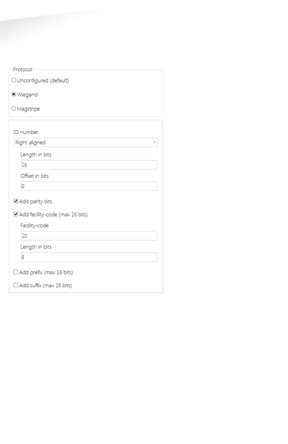
Wiegand configuration example:
The configuration shown below will generate a Wiegand 26-bit message with
facility-code 10. The id-number uses the 16 least significant bits (right aligned).
Mace UID64 B03BF925E6F04D34 id-number 0x4D34 = 19764.
Figure 6: Example wiegand 26-bit configuration

MACE | INSTALLATION GUIDE
Reader configuration
24/30
Magstripe
Select Magstripe to configure the magstripe message output format.
Wiegand output message format:
<0xB><prefix><id-number><suffix><0xF><LRC>
Add start, stop-sentinel and LRC
According to the Magstripe ISO7811/2 standard the messages should begin with a
start-sentinel (0xB) and finish with an stop-sentinel (0xF) and LRC checksum.
Add preamble and postamble clocks
If enabled the Magstripe output will generate 16 preamble clock cycles before the
message and and 16 postamble clock cycles afterwards.
Prefix
Constant prefix value transmitted before the id-number. Max. 16 digits.
ID number
Select to output the id-number complete, left aligned or right aligned.
When left or right aligned specify the id-length and offset in bits.
Convert to decimal
Enable to convert the id-number to a decimal value. Default enabled because
hexadecimal characters should be avoided within the id-number. Hexadecimal
characters are according to the ISO7811/2 standard reserved for message control.
Suffix
Constant suffix value transmitted after the id-number. Max 16 digits.
MACE | INSTALLATION GUIDE
Reader configuration
25/30
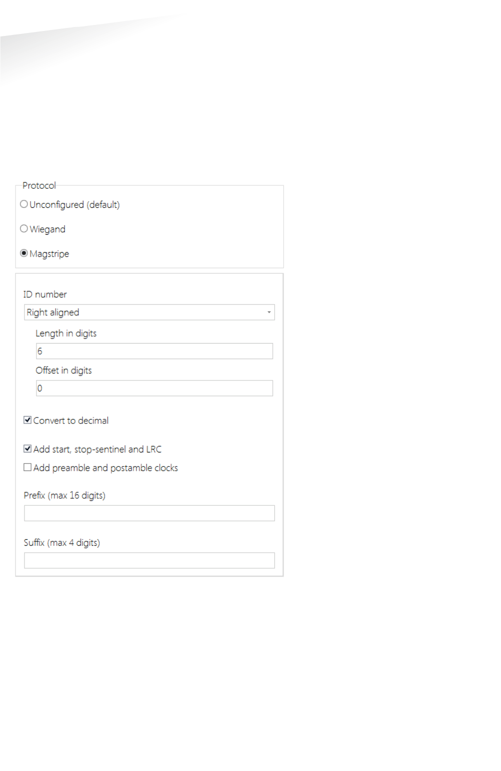
Magstripe configuration example:
The configuration shown below will generate a Magstripe message. The id-number
uses the 6 least significant hex digits (right aligned) and they are converted to 8
decimal digits.
Mace UID64 B03BF925E6F04D34 id-number 0xF04D34 = 15.748.404.
After adding the start, stop-sentinel and LRC this results in message:
B15748404FB
Figure 7: Example magstripe configuration

MACE | INSTALLATION GUIDE
Technical Specifications
26/30
A TECHNICAL SPECIFICATIONS
Technical information
Mace reader MM (QR)
Operating frequency Bluetooth low energy 2.402 – 2.480 GHz
NFC & smartcards: 13.56 MHz
Proximity cards: 120 kHz
Dimensions
150 x 50 x 40 mm [ 5.9 x 2 x 1.6 inch ]
Weight
0.5 kg [ 1.1 lbs ]
Housing
Aluminum (Zamak5) chassis with polycarbonate cover
Color
RAL9006 cover and RAL7016 chassis
Protection
IP65 [ approx.NEMA4x ]
Detection range Bluetooth Low Energy: configurable up to 2m (short), 5m (medium) or 15m (long).
NFC, smartcards and proximity cards: up to 5cm.
Operating temperature
-30...+60°C [ -22...+140°F ]
Power
12 … 24 VDC
Current consumption
0.4A@12VDC, 0.2@24VDC
Input 2 TTL digital inputs for LED control (RED/GREEN)
1 TTL digital input for beeper control
Tamper indication
Yes, magnetic tamper switch
Cable
Fixed cable length of 5 meters [16.4 ft.] included (pigtail)
Cable length Wiegand 150 m [ 500 ft. ] 22AWG
RS485 1200 m [ 3950 ft. ] when installed properly
Interfaces RS485 and USB service interface, additional interfacing options exist. Please consult your
representative.
Output
Wiegand, magstripe (clock & data)
Compliance Europe R&TTE Directive 1999/5/EC
USA: FCC Title 47 Part 15B and 15C
Canada: ISED ICES-003 and RSS210.
Certifications Safety: EN60950-1
EMC: EN301489
Telecom: EN330 330 and EN300 328
Human Exposure assessment: ICNIRP Guidelines, EN62369 and EN50364
UL294

MACE | INSTALLATION GUIDE
Part Numbers
27/30
B PART NUMBERS
Readers
Part number
Description
9565523 MACE MM
9565531 MACE MM QR

MACE | INSTALLATION GUIDE
FCC AND ISED DECLARATIONS
28/30
C FCC AND ISED DECLARATIONS
FCC ID: CGDMACER1 and IC: 1444A-MACER1
FCC (15.19) and ISED Compliance statement
This device complies with part 15 of the FCC Rules and to RSS210 of Industry Canada. Operation is subject to the
following two conditions:
(1) this device may not cause harmful interference, and
(2) this device must accept any interference received, including interference that may cause undesired operation.
Warning (15.21)
Changes or modifications not expressly approved by the party responsible for compliance could void the user’s
authority to operate the equipment.
Cet appareil se conforme aux normes RSS 210 exemptés de license du Industry Canada. L’opération est soumis aux
deux conditions suivantes:
(1) cet appareil ne doit causer aucune interférence, et
(2) cet appareil doit accepter n’importe quelle interférence, y inclus interférence qui peut causer une opération non pas
voulu de cet appareil.
Les changements ou modifications n’ayant pas été expressément approuvés par la partie responsable de la conformité
peuvent faire perdre à l’utilisateur l’autorisation de faire fonctionner le matériel.
FCC and ISED Radiation Exposure Statement
This equipment complies with FCC (OET Bulletin 65) and Canadian radiation exposure limits set forth in RSS-102 for a
uncontrolled environment. This equipment should be installed and operated with a minimum distance of 3 mm
between the radiator and your body. This transmitter must not be co-located or operating in conjunction with any other
antenna or transmitter.
Cet équipement est conforme a RSS-102 limites énoncées pour un environnement non contrôlé. Cet équipement doit
être installé et utilisé avec une distance minimale de 3 mm entre le radiateur et votre corps.
ISED EMC Declaration
This Class B digital apparatus complies with Canadian ICES-003.
Cet appareil numérique de Classe B est conforme à la norme Canadienne ICES-003.
FCC Information to the user (15.106(b))
Note: This equipment has been tested and found to comply with the limits for a class B digital devices, pursuant to part
15 of the FCC Rules. These limits are designed to provide reasonable protection against harmful interference in a
residential installation. This equipment generates, uses and can radiate radio frequent energy and, if not installed and
used in accordance with the instructions, may cause harmful interference to radio communications.
However, there is no guarantee that interference will not occur in a particular installation. If this equipment does not
cause harmful interference to radio or television reception, which can be determine by turning the equipment off and
on, the user is encouraged to try to correct the interference by one or more of the following measures:
• Reorient or relocate the receiving antenna.
• Increase the separation between the equipment and receiver.
• Connect the equipment into an outlet on a circuit different from that to which the receiver.
• Any changes or modifications not expressly approved by the party responsible for compliance could void the user's
authority to operate the equipment.
• To ensure compliance with FCC regulations, use only the shielded interface cables provided with the product, or
additional specified components or accessories that can be used with the installation of the product.

MACE | INSTALLATION GUIDE
Disclaimer
29/30
D DISCLAIMER
This information is furnished for guidance, and with no guarantee as to its accuracy or completeness; its publication
conveys no license under any patent or other right, nor does the publisher assume liability for any consequence of its
use; specifications and availability of goods mentioned in it are subject to change without notice; it is not to be
reproduced in any way, in whole or in part, without the written consent of the publisher.

MACE | INSTALLATION GUIDE
Document revision
30/30
E DOCUMENT REVISION
Version
Date
Comment
1.5
2016-08-18
Power supply specifications updated
1.4
2016-08-18
Added FCC and ISED declarations
1.3
2016-08-08
BLE note added when changing ranging profile
1.2
2016-07-15
Added simple and advanced user mode settings
1.1
2016-07-07
Added reader configuration chapter
1..0
2016-06-21
First preliminary release