NADEX MDM22 Weld Monitor With Bluetooth Transceiver User Manual
NADEX Co.,Ltd. Weld Monitor With Bluetooth Transceiver
UserManual.wiki
>
NADEX
>
MDM22 User Manual
User Manual
Navigation menu
Upload a User Manual
Namespaces
Wiki Guide
HTML
PDF
Info
Views
User Manual
Discussion / Help
Navigation

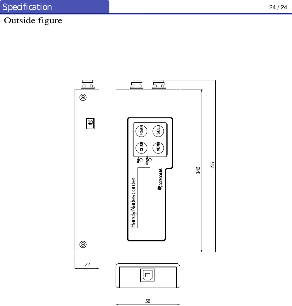
![1 / 24Outline1. OutlineThis machine is a welding current meter capable of measuring the welding current, welding cycle andtip voltage of resistance welders and displaying measured values on the liquid crystal display. Thedevice presents the following features:1) The equipment is small and lightweight, so that it can be easily carried around within the factorypremises.2) A large capacity memory allows storage of up to 10000 average data, 20 each cycle / each msecdata and 1 newest waveform data.3) Data is transmitted to a personal computer and data processing is possible with a personal computer.(The exclusive software for personal computers is required)4) Since the charge battery is built in, it is cordless and can be used.5) Collection of the data in remoteness is possible by radio communications (Bluetooth).6) The connectors for the cables used are all easy-to-use "one-touch" connectors.7) There are two measuring ranges, namely, Lo:2.50 to 19.99kA and 10.00 to 49.99kA. You canselect a range best suited to the current levels you are going to measure.8) The WELD lamp lights up when welding is being detected. Therefore, measuring condition can bemonitored even when you are away from the welding machine.9) The equipment can be used not only with AC welder but also with DC welder, inverter controlledwelder, and AC inverter controlled welder.10) Current consumption is minimized by the auto power-off function, in which power is turned offautomatically when there is no key operation, welding.( [ 10 minutes ], [ 30 minutes ], [ 60 minutes ], and auto-power-off function (OFF))](https://usermanual.wiki/NADEX/MDM22/User-Guide-450630-Page-7.png)
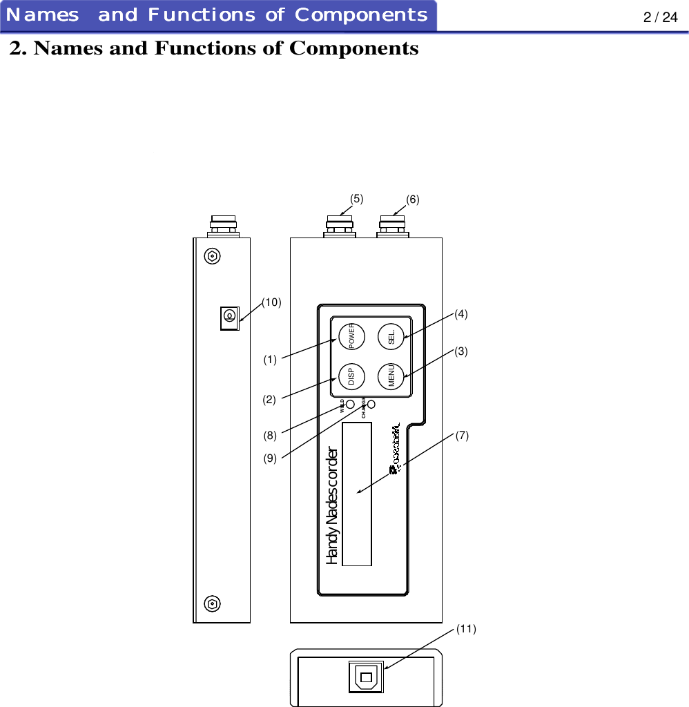
![3 / 24Names and Functions of ComponentsNames and Functions of ComponentsNames and Functions of ComponentsNames and Functions of ComponentsNames and Functions of Components(1) [POWER] keyTurns power on and off.(2) [DISP] keyOperate this key when changing displays or when switching from menu mode to measurementmode.(3) [MENU] keyOperate this key when changing menu items or when switching from measurement mode to menumode.(4) [SEL.] keyUse this key for setting change of menu item.The lighting for LCD turns on at the time of a measured value display.(5) The connector for current measurementConnect the appendant CT cable.(6) The connector of voltage between tipsConnect the appendant tip voltage cable.(7) Liquid crystal displayMeasured value is displayed in measurement mode.The contents of a menu are displayed in menu mode.(8) WELD lampLights up when welding is being done and goes out when it is completed.(9) CHARGE lampLights up during charging. 7. Refer to the Charge Method.(10) Power supply jackConnect the supplied AC adapter when charging.(11) USB connectorConnect the USB cable when performing cable communications.](https://usermanual.wiki/NADEX/MDM22/User-Guide-450630-Page-9.png)
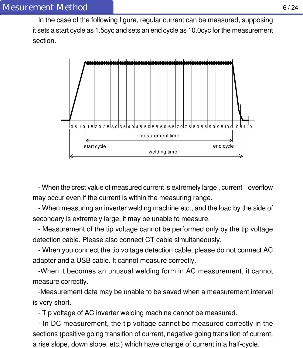
![5 / 24Mesurement Method4. Measuring Method4-1. Measurement Operation Procedure(1) Attach the supplied CT coil to the secondary conductor of the welding machine, and connect thecable to the connector on this device.(2) Turn on power by operating the [POWER] key.(Initial screen)It is in the state which can be measured.(3) Refer to 5. Selection of Menu Function when measuring conditions must be set or changed.(4) In order to measure after a setting end, please press the [DISP] key and make it an initial screen.(5) When you measure the tips voltage , please connect the tip voltage detection cable.Notes on measurement- If you connect the connector with the power on, the trigger may work and ameasurement will be made. But the data from this measurement are invalid.Be sure therefore to turn off power before connecting or disconnecting theconnector.- Since it will be regarded as a weld end if it becomes 50% of peakcurrent in a measurement period when measuring an inverter welding machineetc., a measurement cycle may become long.Moreover, measured value will become small if weld which became long isincluded in measurement.0 . 0 C Y Ak000 .mesurement timewelding timepeak currentweld enddetection level50%](https://usermanual.wiki/NADEX/MDM22/User-Guide-450630-Page-11.png)
![7 / 24Mesurement Method4-2. The display of a liquid crystal display If welding is performed, measured value will be displayed as follows. Moreover, the switch of adisplay can be performed by the [DISP] key.Whenever it presses the [DISP] key, switching display of weld time , weld current , tip voltage , weldcounter , and remain of memory.(Example of a display)The following is displayed when ms is chosen.weld currentweld time(cyc)voltage between tipsweld counterremainder of memoryR E M A I N M . 1 0 0 0 01 5 . 0 C Y 1 1 . 5 0 k AV21.0W . C O U N T 3weld currentweld time(ms)0 m s52 1 1 . 5 0 k A](https://usermanual.wiki/NADEX/MDM22/User-Guide-450630-Page-13.png)
![8 / 24Mesurement MethodThe display of a menu function is displayed as follows.Whenever it presses the [MENU] key, an item changes.(Example of a display)A U T O O F F F FOW E L D M E T H O D A CR A N G E L oI M P U L S E 0U N I T c y cS T A R T C Y5.0E N D 9 9 . 5C YS A V E M O D E O V E RC L E A R M E M .C L E A R C N T .F R E Q U E N C Y H z06](https://usermanual.wiki/NADEX/MDM22/User-Guide-450630-Page-14.png)
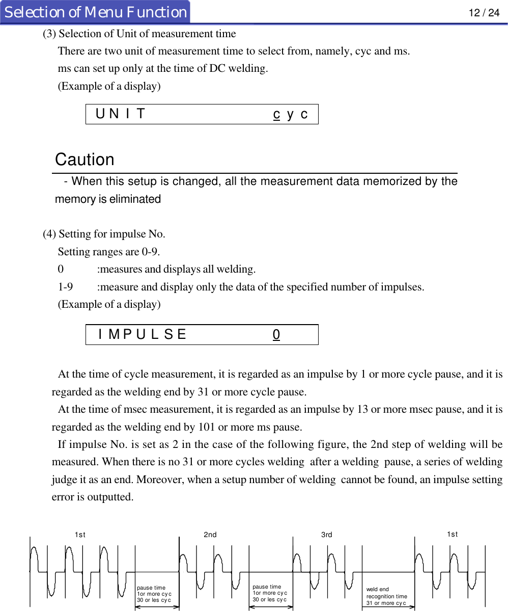
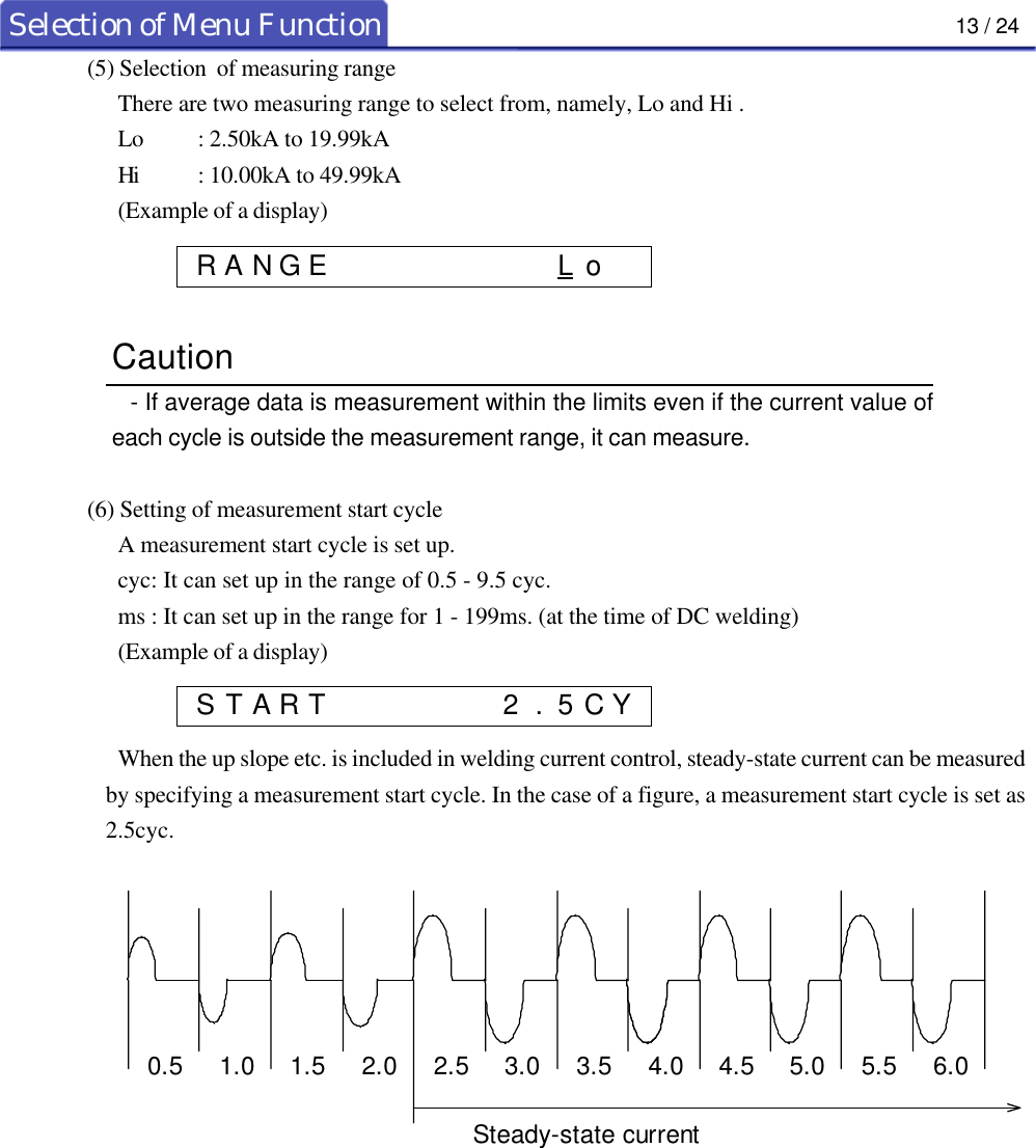
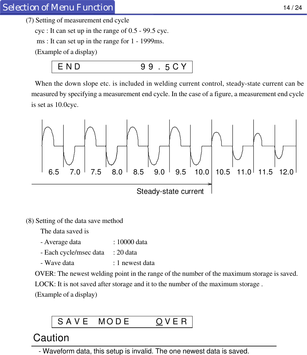
![11 / 24Selection of Menu Function5. Selection of Menu Function5-1. How to select(1) Press the [MENU] key to switch measuring mode to menu mode, and the following display willappear:(Example of a display)(2) To change the item, press the [MENU] key to go on to the next item.(3) After selecting the item to be set, move the cursor to the desired setting value by the [SEL.] key.(4) For further setting of other items, repeat (2) to (3).(5) On completion of setting all the necessary items, press the [DISP] key to switch menu mode tomeasurement mode and start measurement. It cannot measure in menu mode.5-2. Selection Menu Items(1) Selection of welding methodThere are two welding methods to select from, namely, AC welding, DC welding .AC : When measurement is made with a single-phase AC welder.DC :When measurement is made with inverter controlled welder and AC inverter controlled welder.(Example of a display)Caution- The tip voltage of AC inverter welding machine cannot be measured.(2) Selection of frequencyThe local power frequency must be selected.There are two frequency to select from, namely, 50Hz and 60Hz .(Example of a display)Caution- When this setup is changed, all the measurement data memorized by thememory is eliminated- In cyc measurement, any frequency other than 50Hz and 60Hz cannot bemeasured.W E L D M E T H O D A CF R E Q U E N C Y H z06W E L D M E T H O D D C](https://usermanual.wiki/NADEX/MDM22/User-Guide-450630-Page-17.png)
![15 / 24Selection of Menu Function(9) Setting of auto-power-offA setup -OFF / 10M / 30M / 60M can be performed.OFF : A power supply is not turn off until the [POWER] key is pressed.10M : If anything does not have key operation and welding for 10 minutes, a power supply willbe turn off automatically.(Example of a display)(10) Erase of an welding point counterIt chooses whether the welding counter currently recorded is eliminated.(Display)1. When [SEL.] key is pressed, it displays as follows.2. Press [SEL.] key and the data will be cleared.Press [MENU] key and it cancels carrying out.(11) Erase of measurement dataIt chooses whether the measurement data currently recorded on the memory is eliminated.(Display)1. When [SEL.] key is pressed, it displays as follows.2. Press [SEL.] key and the data will be cleared.Press [MENU] key and it cancels carrying out.C L E A R M E M .C L E A R M E M . S U R E ?C L E A R M E M . D O N E !C L E A R C N T .C L E A R C N T . S U R E ?C L E A R C N T . D O N E !A U T O O F F M01](https://usermanual.wiki/NADEX/MDM22/User-Guide-450630-Page-21.png)