NBB Controls and Components TJOY96 Remote Control Transmitter User Manual Revised Manual
NBB Controls + Components AG Remote Control Transmitter Revised Manual
Revised Manual
®
Serial No.:
Stift eindrücken
und Akku herausschieben
Page 1
%
%
%
%
Portable transmitter with two replaceable 7,2 volt NiCd batteries, neck and waist
straps.
Receiver with NBB adapter plate for fastening purposes (PNN-BUS-3), receiver with 4
fixing angles (PNN-BUS-5), with 1 mounting bracket (PNN-R-10) or with integrated
mounting holes (PNN-R-6, -16, -CAN and PNN-Compact).
Multi-pin connecting cable for the receiver according to your specifications.
Automatic battery charger with charging adapter (rapid charging in three hours).
For explanatory notes on obtaining an operating permit please refer to registration docu-
ments enclosed in the appendix of this operating instruction. Observe all applicable work-
safety and accident prevention regulations carefully. Only fully trained, authorized per-
sonnel may use the NBB radio control equipment. Components, etc. built into the NBB
equipment for safety purposes must be regularly inspected.
Failure to observe these recommendations will put both you yourself and others at risk.
Under these circumstances, NBB rescinds the guarantee and any other form of liability.
This radio control unit is designed exclusively for the control of construction machines
and industrial plants. Only under these conditions are the safety systems (EMERGENCY
STOP, zero setting) fully effective. No other form of use is permitted.
Any non-observance of this condition will relieve NBB of all liability.
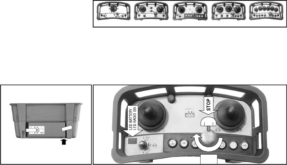
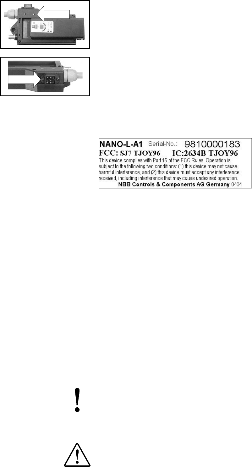
To make the unit ready for use, insert the battery into the battery compartment. To remo-
ve the battery, press in the pin and push out the battery. The power supply to the transmit-
ter is activated with the EMERGENCY STOP switch. (When pressed, the EMERGENCY
STOP switch can also be secured by removing the key cap). The green LED on the trans-
mitter control panel must flash regularly. Commands can now be put in by means of the
controls. The operating period with a charged battery is approximately 8 hours with the
transmitterin continuoususe.
When the red "Battery" indicator lamp lights up, the battery is nearly empty. The transmit-
ter can be operated for approximately 15 minutes more in this condition. During this time,
bring the unit to be controlled to a safe position and install a new battery. Removal of the
battery interrupts the radio link. As a result, the master switch for the unit to be controlled
must beswitched on again. Charge the discharged battery with the charger supplied.
The actual delivery specification is as detailed on the confirmation of order or
the delivery note accompanying the goods!
Even if you are accustomed to working with radio control systems, read these
operating instructions carefully before using this equipment. Only this docu-
ment contains the latest information relating to your NBB radio control system.
If the NBB radio control unit develops a fault, it must be shut down immediately.
The transmitter should be switched off with the EMERGENCY STOP switch. The
connecting cable must be disconnected at the receiver from the connecting so-
cket (terminal) of the unit to be controlled . The repair of the equipment must not
be carried out other than by NBB or an NBB authorized technician.
3. TRANSMITTER Nano-L
Nano-L-A2/1 Nano-L-A2/2 Nano-L-A2/2 Nano-L-A2/3 Nano-L-A1/6
START
2. SAFETY PRECAUTIONS
1. STANDARD SPECIFICATION
Steady light of the green LED : The battery charger is ready for use.
Place the battery in the charger.
If the battery is totally discharged, the yellow LED flashes slowly during pre-charging.
Steady light of the yellow LED: The battery will now be charged.
The yellow LED flashes quickly: The charging process is finished.
No harm will come to the battery if it is left in the charger beyond the required char-
ging time.
Optional: Integrated battery charger if DC-supply: In the receivers PNN-R-6 and PNN-R-
10. In PNN-R-16, -CAN and PNN-Compact rapid charging in about 1 hour. In PNN-BUS-
3about3hours. Use this battery charger only in closed rooms.
The receiver is connected to the unit to be controlled with the multi-pin connecting
cable supplied. Please observe the instructions issued by the manufacturer of the unit
to be controlled!
The power supply of the receiver is generally effected by the connecting cable.
(if existing)
Do not use the charger other than in dry rooms having a min-max tempera-
ture range of 0-40°C! A charged battery is a concentrated energy source.
Never store a charged battery in a toolbox or similar where it could be short-
circuited by metal components (even a key in your trouser pocket can cause
ashortcircuit).
We recommend urgently to realize this connection via a cen-
tral, well accessible, multi-pin plug connector (for example HTS-plug connec-
tor series HE/HB/HN/HA or comparable ones of other manufacturers) to
make possible a quick and clear fault diagnosis in the service case and to
take off the receiver without an expenditure of assembly.
In general, an earth lead is required in case the units to be controlled
have not previously been operated by radio control. Failing this, the
receiver electronic circuit will not receive any power supply. Ensure that
the operating voltage of the receiver complies with the electrical specifi-
cations of the unit to be controlled. The applicable operating voltage is
specified in the supplement.
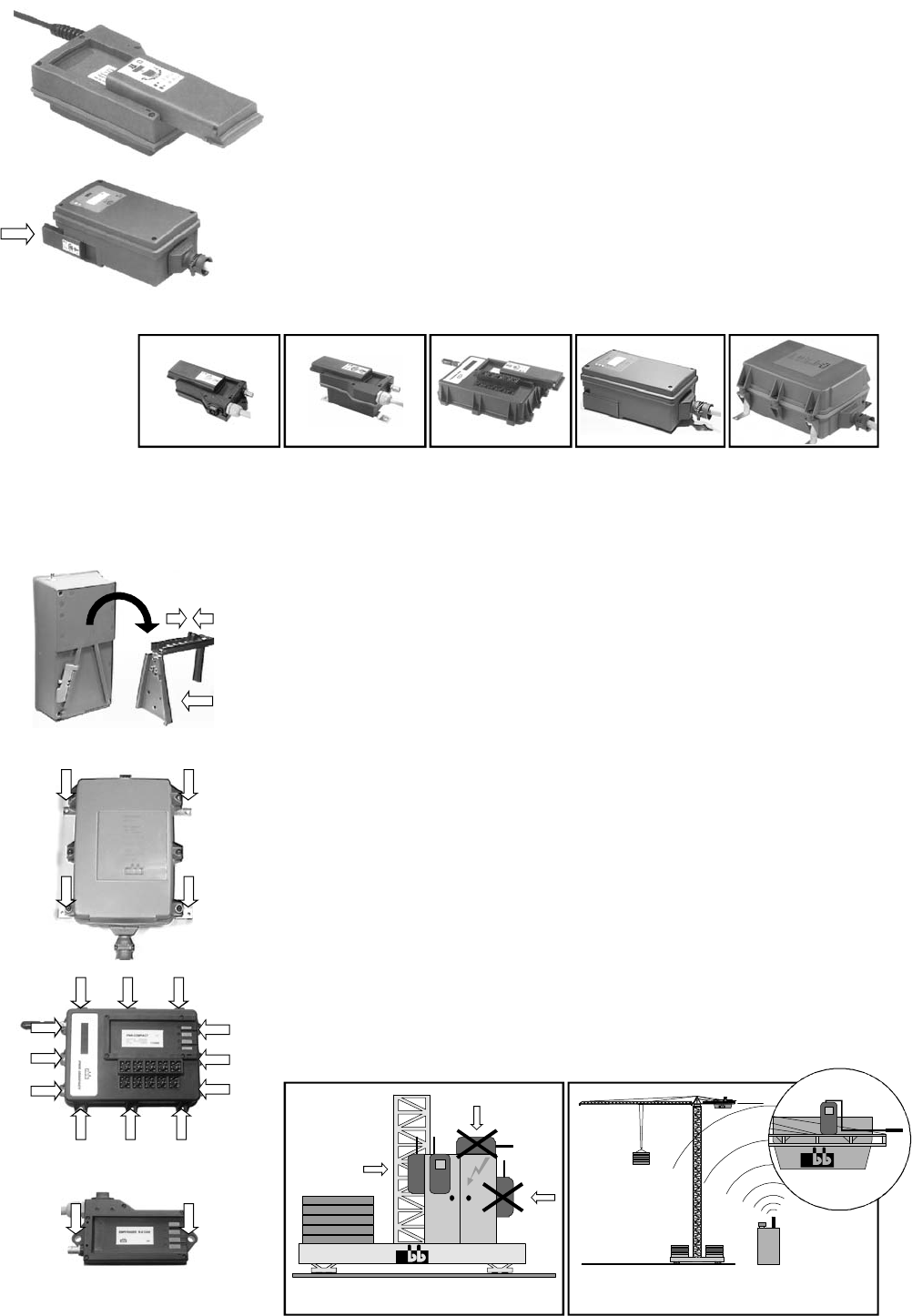
Never expose the receiver to a high pressure cleaning jet. This applies to
the transmitter also.
The receiver should always be fixed vertically at the outside panel of the
switching cabinet. (The antenna should always reach over the top of the
panel.)
You ha ve to make sure that the antenna is not shielded by metal par ts
totally or partly.
Mounting the receiver in a cabine or in a switching cabinet the antenna
should be layed with an extension cable to the outside and be attached with
the fastening strapping as horizontally as possible with distance to the
shielding metal parts.
In general the antenna should always be mounted in such a way so that the
antenna is still visible with each change of position of the transmitter.
%
%
%
%
%
%
PNN-Compact PNN-BUS-3 PNN-BUS-5PNN-R-6, -16, -CAN PNN-R-10
5. RECEIVER
PNN-R-6, -10
PNN-R-16
PNN-R-CAN
PNN-Compact
PNN-BUS-3, -5
Page 2
Mounting possibility
of the PNN-BUS-3 or PNN-BUS-5.
Mounting possibility
of the PNN-Compact
Mounting possibility of the PNN-R-6,
-10, -16 oder des PNN-R-CAN.
WRONG
WRONG
RIGHT
Mounting on a tower slewing crane.
Top slewi ng crane: Mount the antenna w ith
extension cable horizontally.
RIGHT
4. BATTERY CHARGER
Page 3
Safety equipment in the NBB-radio remote control:
In the transmitter
In the receiver:
If the NBB radio remote control is not used for a long period, it is urgently recom-
mended that the batteries be charged now and again (about every 4 weeks).
This prevents deep discharges of the batteries and prolongs their useful life. If
you shut down the NBB radio remote control for a long period, we recommend
you take the battery out of the transmitter.
Frequency change:
ACCIDENT RISK!
EMERGENCY STOP check
Checking the LED's at the receiver PNN-BUS-3:
LED1:
LED2:
LED3:
LED4:
LED5:
,thiscomprisesmainly:
EMERGENCY STOP with automatic disconnection of the power supply.
Automatic zero positioning.
Two diversity units for evaluation of the EMERGENCY STOP signal.
Automatic zero setting when switching back on after radio interruption.
Locking of the radio commands at relay level in the event of a defective EMERGENCY
STOP circuit.
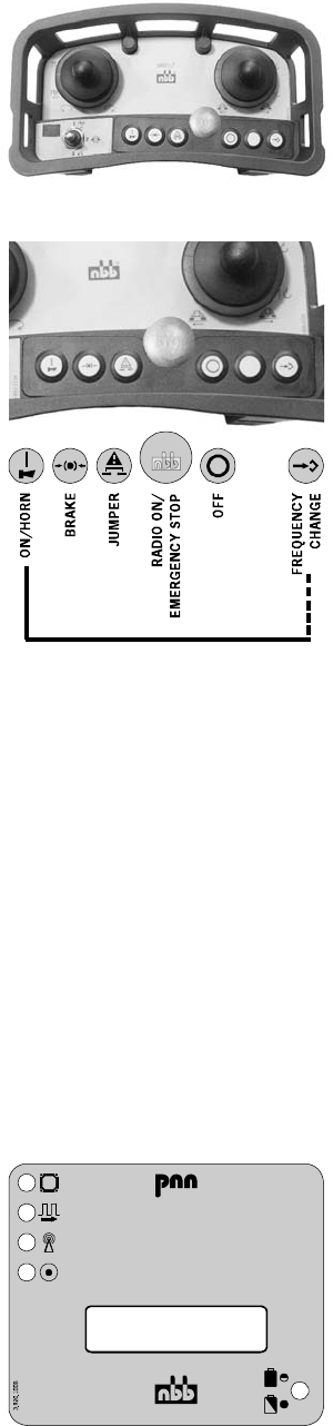
To ensure fault-free operation, please fo llow precisely the following rules for operati on:
The unit to be controlled can only be switched on - it is assumed that the transmitter is
ready to operate - when no command unit is actuated. The command necessary to do so
is triggered by the key "ON/HORN". This triggers a horn signal in the unit to be controlled.
After switch-on of the facility to be controlled, this key is used for repeated emission of the
horn signal in accordance with workingregulations.
To change the frequency, keep the "ON/HORN" key pressed down. Then operate the "FRE-
QUENCY CHANGE" key. If thereceiverlocks into the new frequency, a horn signal is given
(if present) and the unit to be controlled is ready for operation.
(Please observe the particular postal approval regulations of the concerned country.)
To maintain operational safety, a regular function check of the NBB radio remote control is
necessary. In single-shift day-to-day operation, we recommend performing this check at
least once a week. Checking is possible using the display lights provided on the receiver.
To do so, the transmitter must be set to the ready-to-operate state.
First connect just the receiver - the transmitter remains switched off.
Activate the transmitter by unlocking the EMERGENCY STOP switch.
Now check the commands (always start with the lowest stage) and check for
correct reaction of the unit to be controlled.
Ensureinparticularthatthereisnobodyinthedangerarea.
.PresstheEMERGENCYSTOPswitchatthetransmit-
ter until the switch engages. Then observe if the unit to be controlled is switched
off (time to switch off according to the application).
POWER ON. If LED fails to come on, check the power supply.
If the power lead is OK, call in the after-sales service.
HF PRESENT. Steady light when transmitter is switched on
(insignificant for scanner operation).
Flashes evenly during fault-free operation.
Irregular flashing means that the HF channel is probably at fault -
please set another channel.
IfthisLEDcomeson,theHFchannelisatfault.
Charge condition display of battery (only present when charger is
integrated). Steady light when charging a battery.
LED flashes: The battery is charged, the charging process is finished.
%
%
%
%
%
%
%
%
%
%
%
%
%
%
%
FREQUENCY CHANGE
6. OPERATING THE UNIT
7. FUNCTION CHECK
®
MADE IN GERMANY
®
ZULASSUNG - TYPE APPROVAL - AGREMENT - HOMOLOGATION
ISYSTEM
NON EU COUNTRIES:
AUS
CDN
CH
CZ
H
IS
KO
N
no approval necessary
2634231 116A /
2634231 116
BAKOM 95.0720.K.P
45251983
MÜ-40.039-083/96
IS-3236-00
93335
NO96000433-R /
NO95000545-R
1027 /96
YK33-9806
K9VPO C90 T0 01 /
K9VPNN3-5R00 1 /
O5RS-DE96AO
3K43 D/3R 1B9/
SPLS/RX- 439/98
PL
TJY
USA
ZA
1
2
3
4
5
TYPE:
SERIAL NO.:
HF MODULE:
FREQUENCY:
PNN - BU S-3
999 899 4990
S-EM01A0
BAND F
EU COUNTRIES:
X0560
LED RADIO ON
Checking the LED at the receiver PNN-R-16 and PNN-R-CAN:
The Green LED flashes:
Service plug: Information about this programming plug see customized
specifications in the annex.
RADIO PRESENT.
If the LED fails to come on:
1. Check that the transmitter is on.
2. Check the power supply of the receiver.
3. (Optional) Irregular flashing of the LED:
Check or change the current radio channel.
The rating plates state the serial number, the unit model, the HF part model and the
frequency.
Always state the serial number in all your queries.
Please observe the particular postal approval regulations of the concerning country.
Your NBB radio remote control is largely maintenance-free. Nevertheless, please bear in
mindthe followingpoints:
EMERGENCY STOP switch must be easy to move.
Remove any leftover building materials!
During electro-welding work on the unit to be controlled, disconnect the receiver from
thecurrentsupply! Otherwise there is a risk of damage to the receiver's electronic
system!
Check wear and tear parts like dust shield tops regular!
We grant a function warranty for 6 months after the sale date for all NBB radio remote
controls (transmitter, receiver, charger). The warranty covers working time and material
used. Shipping costs shall be charged to the customer. The warranty shall not cover:
wear and tear parts, relays and batteries. The function warranty shall be invalidated in the
case of damage, accident damage, negligence, incorrect use, non-compliance with
operating conditions, non-compliance with operating, testing and maintenance
instructions, and repairs or unit modifications not authorised by NBB. NBB shall not be
liable for indirect damage and reserves the right to decide on repair or replacement.
Do not attempt to continue working with a defective NBB radio remote control. Even
initially minor defects might be the start of a more extensive defect.
Do not try to repair the NBB radio remote control yourself. If there is any fault please
contact your dealer or our company.
%
%
%
%
NOTE:
CAUTION:
This equipment has been tested and found to comply with Part 15 of the FCC
Rules. Operation is subject to the following two conditions: (1) This device may
not cause harmful interference, and (2) this device must accept any interference
received, including interference that may cause undesired operation.
Changes or modifications not expressly approved by the manufacture
could void the user's authority to operate the equipment.
Page 4
SERVICE PLUG
8. RATING PLATES
9. LICENSING
10. MAINTENANCE
11. WARRANTY
12. IN CASE OF DEFECTS
13. FCC

Page 5
TECHNICAL DATA
®
Operating ambient temperature -20 to +65 °C
Insulation class - Protection IP 65
Transmission frequency range 400 - 477 MHz, 25kHz FM
The use of synthesizer technology permits frequencies to be selected in accordance with the appropriate
waveband for the country of use.
Low frequency modulation FSK signal to CCITT V.23
Data repetition rate about 60 ms
Baud rate 1200 baud (bits per sec.)
Range 300 up to 1000 m
Power input
RF ouput <
Weight (without battery) 1,0 kg
Size (L x W x H)
TRANSMITTER
R
Nano-L
PNN-R-6, -10, -16, -CAN, PNN-Compact, PNN-BUS-3, PNN BUS-5
60 - 100 mA
10 mW (This is a generic value. Actual value can be limited by national regulations!)
24,7 x 13,9 x 11,7 cm
Reception frequency range 400 - 477 MHz
Data security:
Generates a CRC code with a Hamming distance = 4.
Generates a neutral position.
Addressing of each transmitter with its own, unique combination (max. 2 possible combinations).
Data reception security: Diversitary evaluators, CRC, EMERGENCY STOP and neutral position bits.
Restart inhibitor if EMERGENCY STOP relay defective. (PNN-BUS-3, PNN-BUS-5, PNN-R-10-N)
Contact loading for EMERGENCY STOP and commands. (PNN-BUS-3, PNN-BUS-5, PNN-R-10-N)
max. switching voltage 250V AC (12V / 24V DC - PNN-R-16, PNN-R-CAN, PNN-Compact)
max. switching current 4A AC (3A DC at 12V / 24V - PNN-R-16, PNN-R-CAN, PNN-Compact)
max. switching power 1000 VA
Weight Size (L x W x H)
PNN-R-6 (with cable) 640 g 13,5 x 8,6 x 5,7 cm
PNN-R-10 (with cable) 740 g 13,5 x 8,6 x 7,3 cm
PNN-R-16, PNN-R-CAN 640 g 18 x 9,7 x 4,4 cm
(potted) 800 g
PNN-Compact (potted) 1,5 kg 21,5 x 16 x 6,5 cm
PNN-BUS-3 3,0 kg 30,6 x 18,1 x 13 cm
PNN-BUS-5 4,7 kg 36,4 x 28,3 x 15,2 cm
7,2V / 1000mAh (Planar: 2 x 1,2V AA-Mignon-R6 batteries)
Operating voltage / external charging unit 12V/24V DC, 110V AC, 230V AC
Operating voltage / PNN-BUS-3 / PNN-BUS-5 40V-230V AC, 8V-32V DC, 12V / 24V DC
Operating voltage / PNN-R-6, -10, -16, -CAN / PNN-Compact 12V / 24V DC
ECEIVER -
BATTERY
CHARGING UNIT
16

APPROVALS AND CERTIFICATES
®
Bedienungsanleitung
Englisch, USA, Kanada, Teile-Nr. 3.150.1051, Stand 11.04
Nano-L, PNN-R-6, -10, -16, -CAN, PNN-Compact, PNN-BUS-3, -5,
Page 6
©NBBControls&ComponentsAG
Otto-Hahn-Straße 1-3
D-75248 Ölbronn-Dürrn
Tel.: 0 72 37 / 9 99 - 0
Fax: 0 72 37 / 9 99 - 1 99
eMail: sales @nbb.de
http://www.nbb.de
We reserve the right to alter specifications without notice.
Approvals:
NON EU COUNTRIES:
AUS no approval necessary
CDN 2634 231 116A / 2634 231 116
CH BAKOM 95.0720.K.P
CZ 45251983
HMÜ-40.039-083/96
HR I-ETS 300 220
IS IS-3236-00
KO 93335
NNO96000433-R/NO95000545-R
PL 1027/96
TH KorKor0704 (MorWor.) / 4436
TJ YK33-9806
USA SJ7 TJOY96 / SJ7 TKEY96
K9VPNN3-5R001
ZA 3K43D/3R1B9/SPLS/RX-439/98
Obtainable at demand:
APPROVAL CERTIFICATE No. G120912F S-DE96A0 05.10.1995
TYPE-EXAMINATION CERTIFICATE No. G129014H S-EM01A0 26.08.1996
Certificate EC type-examination No. TRQ/97213021/AA/00 S-DE96A0 19.11.1997
Statement of Opinion No. 01214115/AA/00 S-DE96A0 19.06.2001
Certificate No. U 950721342002 PNN Nano-S-A2, PNN Nano-E-A2 19.07.1995
Pocket-S, Pocket-V
PNN BUS-3, PNN BUS-E-3
TYPE APPROVAL CERTIFICATE No. 11248-97HH Radio Remote Control 05.02.1998
/PNNSYSTEM
Certificate DIN EN ISO 9001:2000-12 No. 03022 NBB Controls & Components AG 15.07.2003
Federal Approvals Office For Telecommunications Of The Federal Republic Of Germany
telefication
TÜV
Germanischer Lloyd
M-Zert mbH