NCR RSD Atlanta 7730GA2 WIRELESS LAN User Manual USERS MANUAL
NCR Corporation, RSD - Atlanta WIRELESS LAN USERS MANUAL
USERS MANUAL

Model: 7730 Advanced Compliance Solutions FCC ID: JEH7730GA2
Frequency Hopping Spread Spectrum Transmitter
Transmitter Certification
FCC ID: JEH7730GA2
ACS Report Number: 04-0209-15C
Manufacturer: NCR Corporation
Models: 7730-2011, 7730-2012, 7730-2014 and 7730-2015
Manual

NCR RealPrice
Release 3.4
Hardware Service Guide
B005-0000-1491
Issue E
The product described in this book is a licensed product of NCR Corporation.
AIX is a registered trademark of IBM Corporation.
NCR is a registered trademark of NCR Corporation.
NCR RealPrice and DecisioNet are trademarks of NCR Corporation in the United States and/or other
countries.
This product includes software developed by the University of California, Berkeley and its contributors.
It is the policy of NCR Corporation (NCR) to improve products as new technology, components, software, and
firmware become available. NCR, therefore, reserves the right to change specifications without prior notice.
All features, functions, and operations described herein may not be marketed by NCR in all parts of the world.
In some instances, photographs are of equipment prototypes. Therefore, before using this document, consult
with your NCR representative or NCR office for information that is applicable and current.
To maintain the quality of our publications, we need your comments on the accuracy, clarity, organization, and
value of this book.
Address correspondence to:
Manager, Information Products
NCR Corporation
2651 Satellite Blvd.
Duluth, GA 30096
Copyright © 2004
By NCR Corporation
Dayton, Ohio U.S.A.
All Rights Reserved

i
Preface
This guide describes installation and service procedures for the NCR
RealPrice
™
System hardware. NCR RealPrice is the new brand name
for the previously named NCR DecisioNet System.
Safety Warnings
Servicing
Caution: This product does not contain user serviceable parts.
Servicing should only be performed by a qualified service technician.
Lithium Battery Warning
Caution: Danger of explosion if battery is incorrectly replaced.
Replace only with the same or equivalent type as recommended by the
manufacturer. Discard used batteries according to the manufacturer's
instructions.
Attention: Il y a danger d'explosion s'il y a remplacement incorrect de
la batterie. Remplacer uniquement avec une batterie du même type ou
d'un type recommandé par le constructeur. Mettre au rébut les
batteries usagées conformément aux instructions du fabricant.
Battery Disposal (Switzerland)
Refer to Annex 4.10 of SR814.013 for battery disposal.
IT Power System
This product is suitable for connection to an IT power system with a
phase-to-phase voltage not exceeding 240 V.
Peripheral Usage
This product should only be used with peripheral devices that are
certified by the appropriate safety agency for the country of installation
(UL, CSA, TUV, VDE) or those which are recommended by NCR
Corporation.

ii
Environmental Consciousness
NCR is demonstrating its concern for the environment by designing an
intelligent power management system into this terminal that operates
efficiently whether the system is in a stand-alone or network
environment.
Grounding Instructions
In the event of a malfunction or breakdown, grounding provides a
path of least resistance for electric current to reduce the risk of electric
shock. This product is equipped with an electric cord having an
equipment-grounding conductor and a grounding plug. The plug must
be plugged into a matching outlet that is properly installed and
grounded in accordance with all local codes and ordinances. Do not
modify the plug provided – if it will not fit the outlet, have the proper
outlet installed by a qualified electrician. Improper connection of the
equipment-grounding conductor can result in a risk of electric shock.
The conductor with insulation having an outer surface that is green
with or without yellow stripes is the equipment-grounding conductor.
If repair or replacement of the electric cord or plug is necessary, do not
connect the equipment-grounding conductor to a live terminal. Check
with a qualified electrician or service personnel if the grounding
instructions are not completely understood, or if you are in doubt as to
whether the product is properly grounded.
Use only 3-wire extension cords that have 3-prong grounding plugs
and 3-pole receptacles that accept the product’s plug. Repair or replace
damaged or worn cords immediately.

iii

iv
Table of Contents
Chapter 1: Introduction
About This Guide ............................................................1-1
Release 3.1 and Release 3.2 Information................1-1
Chapter Summaries ..................................................1-2
Information Sources .................................................1-3
RealPrice System Installation Reference................1-4
For Windows Installations ..................................1-4
For AIX Installations ............................................1-6
Chapter 2: Installing the Hardware Infrastructure
Chapter Overview ...........................................................2-1
Policy for New Installations ....................................2-2
Installation Recommendations................................2-2
General Layout Instructions....................................2-4
Tools and Supplies....................................................2-6
CBS Installation................................................................2-7
CBS Ethernet Cable Connections............................2-7
CBS Numbering....................................................2-8
CBS Power Supply Cable Connections..................2-9
Sample Store Cabling.........................................2-10
CBS Timeslots......................................................2-11
CBS Hopping Table............................................2-12
CBS Cables...........................................................2-13
CBS Connectors and Status Lights .......................2-17
Data Connectors..................................................2-17
Power Receptacle................................................2-18
CBS Status Lights................................................2-18

v
CBS Identification ...................................................2-19
CBS Installation .......................................................2-20
Alternate CBS Mounting Solution....................2-22
Connecting Ethernet Data Cables.........................2-22
General Comments Regarding Ethernet
Wiring...................................................................2-22
Connecting the Ethernet Hub to the Primary
CBS........................................................................2-23
Connecting Secondary CBSs .............................2-24
Connecting Power Supply Cables ........................2-24
Connecting CBS Power Supplies to AC
Power....................................................................2-24
Connecting CBS Power Supplies to CBSs .......2-25
CBS Antennas..........................................................2-27
Installing CBS Antennas ........................................2-28
Mounting an Antenna to a Suspended
Ceiling ..................................................................2-29
Mounting an Antenna in a Freezer ..................2-31
Hanging an Antenna from a Roof Truss .........2-36
CBS Hardware Configuration...............................2-38
Verify Communication Links................................2-38
Document CBS Network Addressing..............2-39
RealPrice Software Installation, Configuration,
and Testing...............................................................2-39
Chapter 3: Maintenance
Replacing RealPrice Hardware......................................3-1
Windows 2000/NT/XP and AIX Environment
Procedures .................................................................3-2
Stopping and Starting RealPrice Using the
Start Button............................................................3-2
Stopping and Starting at a System Prompt.......3-2

vi
RealPrice Support Utility.....................................3-3
RealPrice for AIX CBS Setup Utility ..................3-3
Replacing a CBS ........................................................3-4
Adding a CBS ............................................................3-5
Replacing Antennas..................................................3-6
Replacing a Receive Antenna..............................3-6
Replacing a Transmit Antenna ...........................3-7
Replacing a Power Supply.......................................3-7
Battery Replacement .......................................................3-9
Updating CBS's Firmware Image (ftpdl)....................3-11
Windows NT/2000/XP Installations...................3-12
AIX UNIX Installations ..........................................3-13
Error Messages....................................................3-14
Updating CBS's Firmware Image – Firmware
Bootloader ......................................................................3-15
Firmware Compatibility ........................................3-15
Firmware Downgradability...................................3-15
Updating the Firmware..........................................3-16
Steps for completing firmware update ................3-17
DHCP Server Configuration .................................3-23
Updating Firmware Before RealPrice Base
Software Installed ...................................................3-25
Using Static IP Addresses ......................................3-26
NCR TFTP Configuration ......................................3-26
Command Line Parameters ..............................3-27
Appendix A: Parts Order Information
CBS ...................................................................................A-1
Model Number.........................................................A-1
Major Model Code ...................................................A-1
Sub Model Code.......................................................A-1

vii
Language Code ........................................................A-2
Power Code...............................................................A-2
Kit Numbers .............................................................A-2
10/100 Unmanaged Switches.................................A-6
Cable Numbers.........................................................A-6
Part Numbers ...........................................................A-7
Glossary

viii
Revision Record
Issue Date Remarks
A Apr. 2003 First issue
B July 2003 Updated to include Firmware Bootloader for
upgrading firmware
C Nov 2003 Added Power Supply Installation
Requirements
Changed the process in Updating CBS’s
Firmware Image – Firmware Bootloader section
D July 2004 Updated Updating CBS’s Firmware Image –
Firmware Bootloader section
E Sept 2004 Updated for 3.4 Hardware Release

ix
Radio Frequency Interference Statements
Federal Communications Commission (FCC)
Information to User
This equipment has been tested and found to comply with the limits
for a Class A digital device, pursuant to Part 15 of FCC Rules. These
limits are designed to provide reasonable protection against harmful
interference when the equipment is operated in a commercial
environment. This equipment generates, uses, and can radiate radio
frequency energy and, if not installed and used in accordance with the
instruction manual, may cause harmful interference to radio
communications. Operation of this equipment in a residential area is
likely to cause interference in which case the user will be required to
correct the interference at his own expense.
NCR is not responsible for any radio or television interference caused by unauthorized
modification of this equipment or the substitution or attachment of connecting cables
and equipment other than those specified by NCR. The correction of interference
caused by such unauthorized modification, substitution or attachment will be the
responsibility of the user. The user is cautioned that changes or modifications not
expressly approved by NCR may void the user's authority to operate the equipment.
RF Exposure (Intentional Radiators Only)
In accordance with FCC requirements of human exposure to
radiofrequency fields, the radiating element shall be installed such that
a minimum separation distance of (20cm) is maintained between the
radiating element and the general population.
Canadian Department of Communications
This Class A digital apparatus complies with Canadian ICES-003.
This digital apparatus does not exceed the Class A limits for radio noise emissions
from digital apparatus set out in the Radio Interference Regulations of the Canadian
Department of Communications.
Cet appareil numérique de la classe A est conforme à la norme NMB-003 du Canada.

x
Le présent appareil numérique n'émet pas de bruits radioélectriques dépassant les
limites applicables aux appareils numériques de la classe A prescrites dans le
règlement sur le brouillage radioélectriques édicté par le ministrère des
Communications du Canada.
Voluntary Control Council For Interference (VCCI)
International Radio Frequency Interference Statement
Warning: This is a Class A product. In a domestic environment this
product may cause radio interference in which case the user may be
required to take adequate measures.

xi
Declaration of Conformity
Manufacturer's Name NCR Corporation
Manufacturer's Address NCR Corporation
Retail Solutions Division – Atlanta
2651 Satellite Boulevard
Duluth, GA 30096-5810
Type of Equipment Information Technology Equipment
Model Number Class 7730-2xxx
Electrical Ratings (Input) 100-120 V/200-240 V, 2.0 A/1.0 A, 50-60 Hz
NCR Corporation, 1700 South Patterson Boulevard, Dayton, OH 45459,
USA, declares that the equipment specified above conforms to the
referenced EU Directives and Harmonized Standards.
EU Directive Harmonized Standard(s)
89/336/EEC (EMC)
1999/5/EC (R&TTE)
EN 301 489-1 V1.2.1: 2000-08
EN 301 489-17 V1.1.1: 2000-09
EN 300 328-1 V1.2.2: 2000-07
I-ETS 300-440, EN 55022, CISPR 16-1
EN 61000-3-2, EN 61000-3-3, EN 61000-4-2,
EN 61000-4-3, EN 61000-4-4, EN 61000-4-5,
EN 61000-4-6, EN 61000-4-11
73/23/EEC (Low Voltage) EN60950:1992 A1 - A4, A11
NCR Corporation
Retail Solutions Division — Atlanta
2651 Satellite Boulevard
Duluth, GA 30096-5810
European Contact:
International IP Counsel
206 Marylebone Road
London, NW1 6LY, England

Chapter 1: Introduction
About This Guide
This guide, for RealPrice System installers and technicians, describes
how to install and service the following RealPrice System components:
• Communication Base Station(s) (CBSs)
• CBS Power Supply(s)
• Transmit and receive antennas
Release 3.1 and Release 3.2 Information
This guide contains details about servicing RealPrice hardware in the
following RealPrice System environments:
• RealPrice for AIX Release 3.1
• RealPrice for Windows NT/Windows 2000/Windows XP Release
3.2
Where applicable, operating environment-specific information is
provided.

1-2 Chapter 1: Introduction
Chapter Summaries
The following is a brief description of each chapter in this guide:
• Chapter 1: Introduction - This chapter provides a brief description of
each chapter in this guide and lists additional RealPrice System
documents that are available.
• Chapter 2: Installing the Hardware Infrastructure - This chapter
describes how to prepare and install CBSs, power supplies,
antennas and cabling.
• Chapter 3: Maintenance - This chapter describes RealPrice hardware
maintenance and replacement procedures and Firmware update
procedures.
• Appendix A: Parts Order Information - This appendix provides
information on model codes, available kits and part order numbers.

Chapter 1: Introduction 1-3
Information Sources
For additional information about the RealPrice System, refer to the
following documents:
Title Document ID Description
RealPrice Site
Preparation Guide
B005-0000-1501 This guide provides site preparation
information for RealPrice RF
infrastructure components.
RealPrice
Software Guide
B005-0000-1479 This guide describes how to install,
configure, and service the RealPrice
System software in the Windows
environments.
RealPrice Utilities
Guide
B005-0000-1487 This guide describes how to use the
RealPrice System utilities to setup RF
infrastructure configuration parameters
and how to diagnose and analyze
RealPrice System hardware and software
problems.
RealPrice Store
Operations Guide
B005-0000-1497 This guide describes how to use the
software's features and functions using
the RealPrice Release 3.2 Console
graphical user interface.
RealPrice AIX CUI
User's Guide
B005-0000-1473 This guide describes how to use the
software's features and functions using
the RealPrice for AIX Release 3.1
character-based user interface (CUI).
RealPrice AIX
HHT User's Guide
B005-0000-1456 This guide describes how to use the
software's features and functions using
the RealPrice for AIX Release 3.1
character-based user interface (CUI) on a
hand held terminal.
RealPrice
Implementation
B005-0000-1250 This CD provides project management
and planning information for site

1-4 Chapter 1: Introduction
Title Document ID Description
Guide installations.
The following document is for NCR internal use only and is available at
http://merlin.corp.ncr.com/
RealPrice
Certification Site
Survey Policy
497-0421218 This policy describes how to certify and
document a completed installation's site
configuration for support purposes.
RealPrice System Installation Reference
The planning and installation of a RealPrice System is a coordinated
effort between various NCR organizations, third-party hardware and
software vendors, and the customer over an extended period of time.
The following chart lists the primary areas of installation activity and
identifies where details may be found to support the personnel
performing the activity.
For Windows Installations
Activity Task Reference
Site Planning Site Surveys Implementation Guide
Install RF Infrastructure Run power, communication,
and antenna cables
Install Power Supplies, mount
CBS units and CBS antennas
Hardware Service Guide
Chapter 2
Configure CBS IP
Addresses
Setup static IP Addresses
using RealPrice Support
Utility (dnutils)
Software Guide
Chapter 4
Verify network Ping all CBS units Utilities Guide
Chapter 3
Document CBS
Network Addressing
Record CBS Numbers, MAC
Addresses, and IP Addresses
Software Guide
Chapter 4

Chapter 1: Introduction 1-5
Activity Task Reference
Install RealPrice
Software
Load the RealPrice Base
Application
Software Guide
Chapter 2
Configure RealPrice
Software for CBS units
Modify CBS Configuration file
(dncbsconfig.xml) using
RealPrice Support Utility
(dnutils)
Software Guide
Chapter 4
Configure CBS Units Set store-specific CBS
parameters using RealPrice
Support Utility (dnutils)
Timeslots
Hopping Table
Software Guide
Chapter 4
Confirm CBS
Functionality
Verify CBS Diagnostic Log
and Tally information using
RealPrice Support Utility
(dnutils)
Utilities Guide
Chapter 2
Perform Power Supply
Configuration Test
Verify that the correct number
of CBS units are connected to
each Power Supply
Three (3) CBS units are
connected to each 24V Power
Supply.
Five (5) CBS units are
connected to each 48V Power
Supply.
Utilities Guide
Chapter 4
Perform Healthcheck on
all CBS receive antennas
Use Coverage Test utility
(dncalib) to display RSSI
(Received Signal Strength
Indicator) data
Utilities Guide
Chapter 4
Certify the Site Use the RF Certification Utility
to confirm RF infrastructure
functionality and coverage
Implementation Guide and
RF Certification Utility
Guide

1-6 Chapter 1: Introduction
Activity Task Reference
area
Perform Initial Load Initialize RealPrice Database
and Electronic Shelf Labels
Implementation Guide and
Initial Load Process Guide
Confirm Integration
Software
Run Data Reader Test in the
RealPrice Support Utility
(dnutils) after all software is
installed
Utilities Guide
Chapter 2
For AIX Installations
Activity Task Reference
Site Planning Site Surveys Implementation Guide
Install RF Infrastructure Run power, communication,
and antenna cables
Install Power Supplies, mount
CBS units and CBS antennas
Hardware Service Guide
Chapter 2
Configure CBS IP
Addresses
Setup static IP Addresses Installation and Service
Guide
Chapter 4
Verify network Ping all CBS units Installation and Service
Guide
Chapter 3 and 7
Document CBS
Network Addressing
Record CBS Numbers, MAC
Addresses, and IP Addresses
Installation and Service
Guide
Chapter 3
Install RealPrice
Software
Load the RealPrice Base
Application
Installation and Service
Guide
Chapter 5
Configure RealPrice Modify CBS Configuration file
(dncbsconfig.xml) using CBS
Installation and Service
Guide

Chapter 1: Introduction 1-7
Activity Task Reference
Software for CBS units Setup Utility (dncbssetup) Chapter 7
Configure CBS Units Set store-specific CBS
parameters using CBS Setup
Utility (dncbssetup)
Timeslots
Hopping Table
Installation and Service
Guide
Chapter 7
Confirm CBS
Functionality
Verify CBS Diagnostic Log
and Tally information using
CBS Setup Utility (dncbssetup)
Installation and Service
Guide
Chapter 7
Perform Power Supply
Configuration Test
Verify that no more that three
(3) CBS units are connected to
each Power Supply
Installation and Service
Guide Chapter 7
Perform Healthcheck on
all CBS receive antennas
Use Coverage Test utility
(dncalib) to display RSSI
(Received Signal Strength
Indicator) data
Installation and Service
Guide Chapter 7
Certify the Site Use the RF Certification Utility
to confirm RF infrastructure
functionality and coverage
area
Implementation Guide and
RF Certification Utility
Guide
Perform Initial Load Initialize RealPrice Database
and Electronic Shelf Labels
Implementation Guide and
Initial Load Process for AIX
Guide
Confirm Integration
Software
Run RealPrice Data Reader
Test (dndatareader.exe) after
all software is installed
Installation and Service
Guide
Chapter 7

Chapter 2: Installing the Hardware Infrastructure
Chapter Overview
This chapter describes how to install the RealPrice hardware
infrastructure. This includes the following components:
• CBSs
Note: The RealPrice Release 3.4 Communication Base Station (CBS) is
a 10/100Base-T Ethernet device and may be used in a 10 Base-T or
100Base-T Ethernet network. CBS power supplies
• Data and power cables
• Transmit and receive antennas
For information about ordering these parts, refer to Appendix A.
Note: After the RealPrice hardware is installed, the RealPrice software
must be configured and the site must be RF certified. Refer to the
following documents:
• "Chapter 4: CBS Configuration" in the RealPrice Software Guide
(B005-0000-1479)
• RealPrice RF Certification Utility Guide (AIP-000269) or the "Certify
RF Infrastructure" section of the RealPrice Implementation Guide
(B005-0000-1250).

2-2 Chapter 2: Installing the Hardware Infrastructure
Policy for New Installations
It is the CBS installer's responsibility to ensure that CBS firmware
revision levels are correct at the time of installation.
The correct firmware level is one of the following:
1. The latest firmware version available at www.ncr.com -> Support -
> Drivers and Patches -> Retail Support Files -> Retail RealPrice
Support Files.
2. A customer-specified firmware version. A small number of
customers do not allow installation of any new firmware that has
not been integration tested in their lab. The installation project
planner (usually NCR Professional Services) informs if this is the
case.
Due to supply chain logistics, new CBSs may not come pre-installed
with the latest firmware. Always verify.
To keep up to date, subscribe to the RealPrice software/firmware
update mailing list. NCR uses this list to announce new firmware
releases. Subscribe by sending an email to majordomo@lists.ncr.com
with "subscribe realpriceupdates" in the body of the message.
Installation Recommendations
• The most efficient way to install the RealPrice hardware
infrastructure is in one pass through the store. Install the CBSs,
antennas, power cables, and data cables all at the same time.
• Whenever possible the CBSs should installed at 15 feet or lower so
that serviceability by the ladder is possible.
• The primary CBS must be installed so that it is serviceable from the
floor.
• Label all CBSs, antennas, and data cables. Document how
components are labeled for future reference.
• Label all power supplies and 48V cables for serviceability.

Chapter 2: Installing the Hardware Infrastructure 2-3
• Power supply labels should indicate which CBSs they power,
and the fact that they are part of the RealPrice ESL system.
• The 48V cable labels should indicate which CBS they lead to.
• Neatness makes servicing the system much easier.
• Do not mount the power supply AC main power strips on the floor
or in a place where they might be accidentally switched off.
• Do not mount power supplies on the floor or in a place where wires
might get accidentally pulled out.
• Provide slack in cables, especially in receive antenna cables.
• Test the system as it is being installed. Refer to “Chapter 3, CBS
Network Utilities and Diagnostic Tools” in the NCR Utilities Guide
(B005-0000-1487) for information on testing.
• Provide AC power that meets NCR requirements for the power
supplies. Refer to the "Power, Grounding and Distribution
Requirements" section of the RealPrice Site Preparation Guide (B005-
0000-1501).
• Test wiring as it is installed. Some installation problems are
extremely difficult to diagnose later.
• RealPrice Release 3.x requires the RF infrastructure to be connected
to the site's RealPrice Software Controller to test the infrastructure.
Refer to the following for information on testing the infrastructure
and site certification:
• RealPrice Implementation Guide (B005-0000-1250)
• RealPrice RF Certification Utility Guide (AIP-000269)
• RealPrice III Certification Site Survey Policy (497-0421218)

2-4 Chapter 2: Installing the Hardware Infrastructure
General Layout Instructions
• The cable length between any two devices (10/100Base-T
compatible Ethernet hub to CBS or CBS to CBS) cannot exceed 100
m (328 ft.).
• The maximum number of Ethernet levels beyond the primary CBS
is three (3).
• The maximum total cable length is as follows:
Cable Maximum Cable Length
Ethernet (primary CBS to last CBS in chain) 300 m (984 ft.)
Power supply to last CBS in the chain 162 m (532 ft.)
• Use only NCR authorized communication cable.
• Communication cables must be secure and locked into their
connectors.
• The maximum number of CBSs per store is 85.
• If the communication cable is routed through an exposed area, such
as up the side of a wall, across the top of a freezer where
merchandised is stacked, or in an elevator shaft, it must be in a
conduit and the conduit must be connected to the building ground.
• The minimum distance between a communication cable and a
fluorescent, neon, or incandescent light is 30 cm (12 in.).
• Minimum distance between a transmit or receive antenna and a
neon light is 2.43 m (8 ft.).
• All communication cable connections must be protected from
electrical and mechanical deterioration. The deterioration of
communication cable connections due to corrosion or electrolysis,
especially in a humid or corrosive atmosphere, may result in
electrical noise.

Chapter 2: Installing the Hardware Infrastructure 2-5
• Minimum distance between the transmit antenna and any receive
antenna connected to 1 Watt or 500 mW CBS's is 9.2 m (30 ft.).
Minimum distance between the transmit antenna and any receive
antenna on a 100 mW CBS is 6.2 m (20 ft.). There is no minimum
distance between two transmit antennas.
• The minimum distances between a communication cable and
electrical equipment/associated power cables are as follows:
Maximum Rated Circuit Power Unshielded Power Cables Shielded Power Cables
1 kVA 30.5 cm (14 in.) 2.54 cm (1 in.)
2 kVA 45.7 cm (18 in.) 5.08 cm (2 in.)
5 kVA 60.9 cm (24 in.) 15.24 cm (6 in.)
Over 5 kVA 152.4 cm (60 in.) 30.48 cm (12 in.)
• All interconnecting wiring between the Ethernet hub, CBSs, and
power supplies is low voltage wiring. This wiring must conform to
all local and national electrical codes for the routing of commercial
signal wire.
• Do not route communication cables outside the building.

2-6 Chapter 2: Installing the Hardware Infrastructure
Tools and Supplies
RealPrice infrastructure installers must have access to the tools
typically found in an electrician's tool box. Additional tools and
supplies an installation team may require are shown in the following
table.
Tool/Supply Quantity
Cable ties 10 per CBS
RJ45 Modular Jacks 2 per cable plus spares
RJ45 crimp kit 1
Low-torque electric screw driver 1
ESL removal tool 1 per installer
Lift truck 1
CAT5 cable tester 1
Chapter 2: Installing the Hardware Infrastructure 2-7
CBS Installation
The following sections describe the preparation, cabling, and
installation of the CBS and its related components.
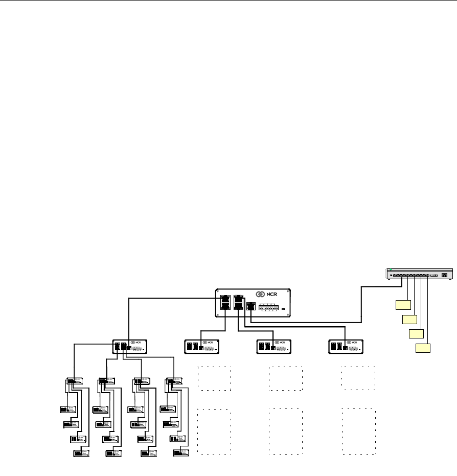
CBS Ethernet Cable Connections
The RealPrice CBS uses a star topology and has an integrated Ethernet
switch that can connect to three other CBSs. RealPrice supports up to
three (3) levels below the primary CBS. This topology results in the 85
CBS maximum mentioned in the “General Layout Instructions”
section. The following illustration shows an example 85 CBS
configuration, its Ethernet cable connections, and the maximum
number of CBSs on each level.
D
D
D
D
Power
Ground
+48V DC
31
42
Uplink
D
D
Power
Ground
+48V DC
31
42
Uplink D
D
Power
Ground
+48V DC
31
42
Uplink
D
D
Power
Ground
+48V DC
31
42
Uplink 13
D
D
Power
Ground
+48V DC
31
42
Uplink
D
D
Power
Ground
+48V DC
31
42
Uplink
D
D
Power
Ground
+48V DC
31
42
Uplink
D
D
Power
Ground
+48V DC
31
42
Uplink
D
D
Power
Ground
+48V DC
31
42
Uplink
D
D
Power
Ground
+48V DC
31
42
Uplink
D
D
Power
Ground
+48V DC
31
42
Uplink
D
D
Power
Ground
+48V DC
31
42
Uplink
D
D
Power
Ground
+48V DC
31
42
Uplink
D
D
Power
Ground
+48V DC
31
42
Uplink
D
D
Power
Ground
+48V DC
31
42
Uplink
D
D
Power
Ground
+48V DC
31
42
Uplink
D
D
Power
Ground
+48V DC
31
42
Uplink
D
D
Power
Ground
+48V DC
31
42
Uplink
D
D
Power
Ground
+48V DC
31
42
Uplink
D
D
Power
Ground
+48V DC
31
42
Uplink
D
D
Power
Ground
+48V DC
3
1
42
UplinkD
D
Power
Ground
+48V DC
3
1
42
UplinkD
D
Power
Ground
+48V DC
3
1
42
Uplink
D
D
Power
Ground
+48V DC
31
42
Uplink
D
D
Power
Ground
+48V DC
31
42
Uplink
D
D
Power
Ground
+48V DC
31
42
Uplink
D
D
Power
Ground
+48V DC
31
42
Uplink
D
D
Power
Ground
+48V DC
31
42
Uplink
D
D
Power
Ground
+48V DC
31
42
Uplink
D
D
Power
Ground
+48V DC
31
42
Uplink
D
D
Power
Ground
+48V DC
31
42
Uplink
D
D
Power
Ground
+48V DC
31
42
Uplink
D
D
Power
Ground
+48V DC
31
4
2
Uplink
D
D
Power
Ground
+48V DC
31
4
2
Uplink
D
D
Power
Ground
+48V DC
31
4
2
Uplink
D
D
Power
Ground
+48V DC
31
42
Uplink
D
D
Power
Ground
+48V DC
31
42
Uplink
D
D
Power
Ground
+48V DC
31
42
Uplink
D
D
Power
Ground
+48V DC
31
42
Uplink
D
D
Power
Ground
+48V DC
31
42
Uplink
D
D
Power
Ground
+48V DC
31
42
Uplink
D
D
Power
Ground
+48V DC
31
42
Uplink
D
D
Power
Ground
+48V DC
31
42
Uplink
D
D
Power
Ground
+48V DC
31
42
Uplink
D
D
Power
Ground
+48V DC
3
1
42
UplinkD
D
Power
Ground
+48V DC
3
1
42
UplinkD
D
Power
Ground
+48V DC
3
1
42
Uplink
D
D
Power
Ground
+48V DC
31
42
Uplink
D
D
Power
Ground
+48V DC
31
42
Uplink
D
D
Power
Ground
+48V DC
31
42
Uplink
D
D
Power
Ground
+48V DC
31
42
Uplink
D
D
Power
Ground
+48V DC
31
42
Uplink
D
D
Power
Ground
+48V DC
31
42
Uplink
D
D
Power
Ground
+48V DC
31
42
Uplink
D
D
Power
Ground
+48V DC
31
42
Uplink
D
D
Power
Ground
+48V DC
31
42
Uplink
D
D
Power
Ground
+48V DC
31
42
UplinkD
D
Power
Ground
+48V DC
31
42
UplinkD
D
Power
Ground
+48V DC
31
42
Uplink
WS
WS
WS
WS
Primary CBS
Level 1
( 4 CBSs)
CBS
121-124
CBS 1
11 12 14
21395
Power
Ground
+48V DC
31
42
D
D
Power
Ground
+48V DC
31
42
Uplink 113
111 112 114
Level 2
( 16 CBSs)
1111
CBS
141-144
CBS
131-134
Level 3
( 64 CBSs)
1121
1122
1123
1124
1112
1113
1114
1131 1141
1142
1143
1144
1132
1133
1134
CBS
1211
-
1244
CBS
1311
-
1344
CBS
1411
-
1444
Ethernet Switch
Uplink

2-8 Chapter 2: Installing the Hardware Infrastructure
CBS Numbering
CBS’s are identified in the CBS Manager section of the RealPrice CBS
configuration file (DNCBSCONFIG.XML) with a unique number and a
host name or IP address. Using the numbering scheme shown in the
illustration helps identify the level in which the CBS is connected in the
topology when running diagnostic tests and analyzing diagnostic logs.
This scheme is as follows:
• Primary CBS = always 1
• Level 1 = CBS 11-14
• Level 2 = CBS 111-144
• Level 3 = CBS 1111-1444
CBS configuration details are described in “Chapter 4: CBS
Configuration” in the RealPrice Software Guide (B005-0000-1479).
Chapter 2: Installing the Hardware Infrastructure 2-9
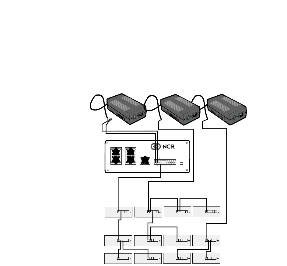
CBS Power Supply Cable Connections
The CBS Power Supply can support up to five (5) CBSs. The following
illustration shows power supply cable connections for a 13 CBS
configuration using 3 power supplies. This cabling scheme may be
extended to support 85 CBSs.
D
D
Power
Ground
+48V DC
31
42
Uplink
21393
Level 1
Level 2
Level 3
Primary CBS
CBS Power Supplies
2-10 Chapter 2: Installing the Hardware Infrastructure
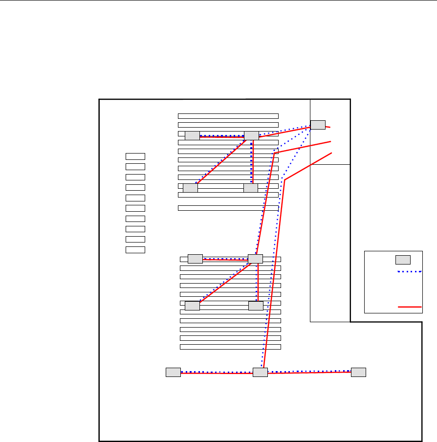
Sample Store Cabling
The following illustration shows a store layout with 12 CBSs and 3
power supply cables originate in the back office and are bundled
together, where possible, to accomplish this configuration.
Checkout
Bakery
Produce Dairy Meat and Deli
Legend
CBS
Cable
Power
Supply
Cable
112
Back
Office
PS1PS1
PS2
PS3
1
11111
112 113
121 12
122 123
131 13 132
21399

Chapter 2: Installing the Hardware Infrastructure 2-11
CBS Timeslots
Each CBS uses two (2) of the 24 available Timeslots to communicate
with the ESLs in its coverage area. Timeslots are assigned in pairs (1,
13; 2, 14; 3, 15; and so forth) to each CBS.
To provide the most efficient communication network, adjacent CBSs
must have timeslots that differ. The optimal difference is 6, but in larger
installations, this may be difficult to accomplish.
The timeslots for the CBSs shown in the Sample Store Cabling
illustration in the previous section could be set as follows to achieve
efficient communications:
CBS Number CBS ID Timeslot ID 1 Timeslot ID 2
1 1 12 24
2 11 4 16
3 21 7 19
4 22 10 22
5 23 1 13
6 12 5 17
7 24 2 14
8 25 8 20
9 26 11 23
10 13 6 18
11 27 3 15
12 28 9 21
2-12 Chapter 2: Installing the Hardware Infrastructure
CBS timeslot configuration can be done using the CBS Setup options in
the RealPrice Support Utility (dnutils.exe) after the RealPrice Base
Software is installed and the RealPrice CBS Configuration file is
modified. Refer to “Chapter 2: The RealPrice Support Utility” in the
RealPrice Utilities Guide (B005-0000-1487) for details on how to use this
utility to view and set CBS timeslots for Windows installations. Refer
to the "dncbssetup (CBS Setup Utility)" section of “Chapter 7: Testing
and Troubleshooting in AIX” in the RealPrice Installation and Service
Guide (B005-0000-1247) for details on how to use this utility to view and
set CBS timeslots for AIX UNIX installations.
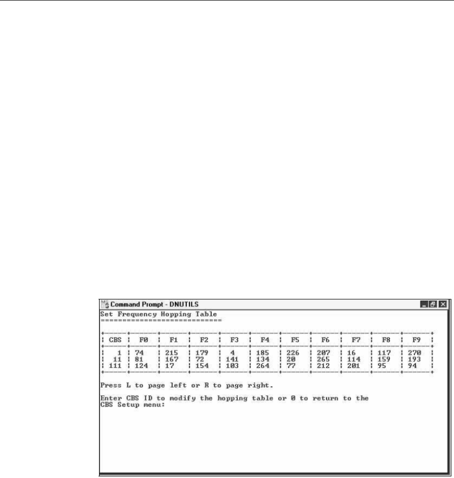
CBS Hopping Table
Each CBS is assigned a set of hopping frequencies in the 2.4 gHz range
that it uses to communicate with the ESLs. There are 565 frequencies
available numbered 0-564. CBS models have 83 frequencies in their
hopping table associated with a Hopping Table Index (0-82) in a single
frequency band. Local regulation may limit the number of frequencies
permitted. For example, in France, only 142 frequencies are used.
To provide the most efficient communication network, CBSs must not
have the same hopping table.

Chapter 2: Installing the Hardware Infrastructure 2-13
Hopping frequencies are assigned during the manufacturing process,
but can be modified using the RealPrice Support Utility. Refer to
“Chapter 2: The RealPrice Support Utility” in the RealPrice Utilities
Guide (B005-0000-1487) for details on how to use this utility to view and
set the CBS Hopping Table after the RealPrice Base Software for
Windows NT/2000/XP is installed. Refer to the "dncbssetup (CBS
Setup Utility)" section of “Chapter 7: Testing and Troubleshooting in
AIX” in the RealPrice Installation and Service Guide (B005-0000-1247) for
details on how to view and set the CBS Hopping Table after the
RealPrice Base Software for AIX is installed.
CBS Cables
The following cables are supplied by NCR.
Cable ID
(Part Number) Description Length
m (ft.) Connect From Connect To Comments
1416-C465-0018
(230-0146539)
Transmit
antenna cable
(plenum
rated)
1.8 (5.9) CBS transmit
antenna
connector
Transmit
antenna
Has TNC screw-
on connectors
1424-C057-0180
(230-0134951)
Receive
antenna cable
(plenum
rated)
18 (59) CBS receive
antenna
connector
A, B, C, or D
Receive antenna
Has BNC
connectors
Cable included
with receive
antenna kit.
1416-C520-0150
(230-0134953)
Receive
antenna cable
(plenum
rated)
15 (49) CBS receive
antenna
connector
A, B, C, or D
Receive antenna
Has BNC
connectors
Cable included
with receive
antenna kit
Use this cable
with 100 mW
CBSs

2-14 Chapter 2: Installing the Hardware Infrastructure
Cable ID
(Part Number) Description Length
m (ft.) Connect From Connect To Comments
7730-K055-
V002 Kit
(497-0436081)
Receive
antenna cable
(plenum
rated)
12 (39) CBS receive
antenna
connector
Receive antenna Has BNC
connectors
Cable included
with receive
antenna kit
Receive antenna
cable is 6 meters
(19 feet) long
Use for freezer
installation
CBS power
supply pigtail
First of up to
three CBSs
Bulk cable
from
third-party
Power cable
CBS CBS
Refer to tables in
next section
CBS CBS Bulk cable
from
third-party
Data cable
Refer to tables in
next section
Note: All cables conform to type CL2P.
Power and Data Cables
The power and data cables must be purchased in bulk from a third
party. NCR recommends using the Belden cables described in the
following table.
Note: The wire colors referenced in the text and illustrations that
follow are consistent with the recommended Belden cables. If you are
using a comparable cable from another manufacturer, your wire colors
may be different.

Chapter 2: Installing the Hardware Infrastructure 2-15
Cable Use
Manufacturer Manufacturer
Part Number Description
Power Belden 6100UE 2 conductor, 14 AWG (2 mm2) stranded,
unshielded, plenum rated
Power Belden 5100UE 2 conductor, 14 AWG (2 mm2) stranded,
unshielded, non-plenum rated
Data Belden 1585A 4 pair, CAT5, 24 AWG (0.2 mm2) solid,
unshielded, plenum rated
Data Belden 1583A 4 pair, CAT5, 24 AWG (0.2 mm2)
`11`solid, unshielded, non-plenum rated
Note: When installing into a plenum type ceiling, plenum rated wire
may be required by local or national electrical codes. Some suspended
ceilings are considered plenums; open ceilings are not. Plenum rated
wire is typically more costly than non-plenum. Choose the correct
wire type based on your applicable local and national electrical codes.
For general reference, CBS wiring falls under NEC (National Electrical
Code) Class 2 type.

2-16 Chapter 2: Installing the Hardware Infrastructure
Power Cable Connectors
Each CBS is shipped with a 10-wire connector
that plugs into the 10-wire power receptacle.
The only tool required to install the power
cable into the connector is a small screwdriver.
21390
Data Cable Connectors
An RJ45 connector is required for each of the CBSs data connectors.
The RJ45 connectors must be purchased from a third party. A crimp
tool is required to install the data cable into the RJ45 connector.
The following table provides information about RJ45 connectors and
crimp tools.
Manufacturer Manufacturer
Part Number Quantity Description
AMP 5-557315-1
5-557315-2
5-557315-3
5-557315-4
10,000 (loose)
500 (loose)
1,000 (10 boxes of
100)
1,000 (40 bags of 25)
RJ45, 8-position,
unshielded type1
AMP 1-231666-1 1 Crimp tool2
Ideal 33-652 1 Crimp tool2
Ideal 30-560 1 AMP die for Ideal
crimp tool3
1 Use any comparable RJ45 connector compatible with your crimp
tool.
2 Use any crimp tool compatible with your RJ45 connector.
3 Necessary only when using AMP connectors and Ideal crimp tool.
Chapter 2: Installing the Hardware Infrastructure 2-17
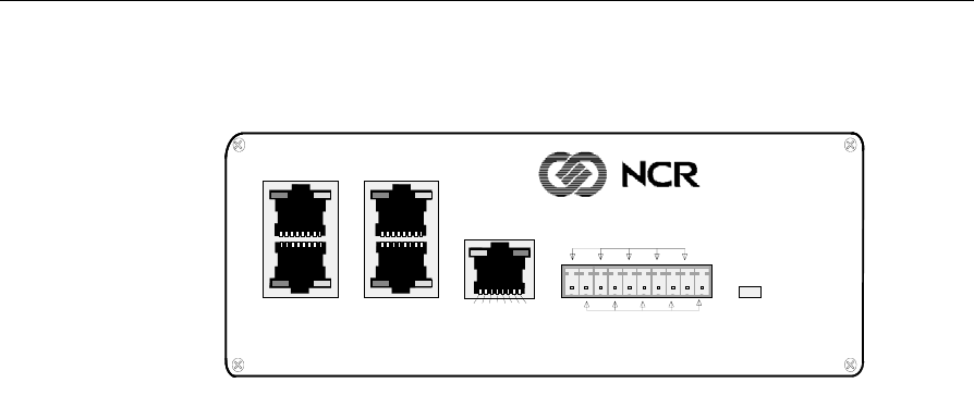
CBS Connectors and Status Lights
21391
Power
Ground
+48V DC
31
42
Uplink
87654321
Data Connectors
The CBS has four data connectors:
Uplink – used to connect to the in-store hub or a higher level CBS hub as
shown in the illustration in the "CBS Ethernet Cable Connections"
section of this chapter.
1, 2, 3, and 4 – used for downlink connections to lower level CBS hubs
Data connector pin and signal use is as follows:
• Pins 1, 2, 3, and 6 carry standard Ethernet transmit and receive data
between the Ethernet Hub and the primary CBS and between all
CBS's as defined in ISO/IEC Standard 8802.3 paragraph 14.5.1.
• Pins 4, 5, 7, and 8 are used for RealPrice transmit and receive timing
signals between all CBSs.
2-18 Chapter 2: Installing the Hardware Infrastructure
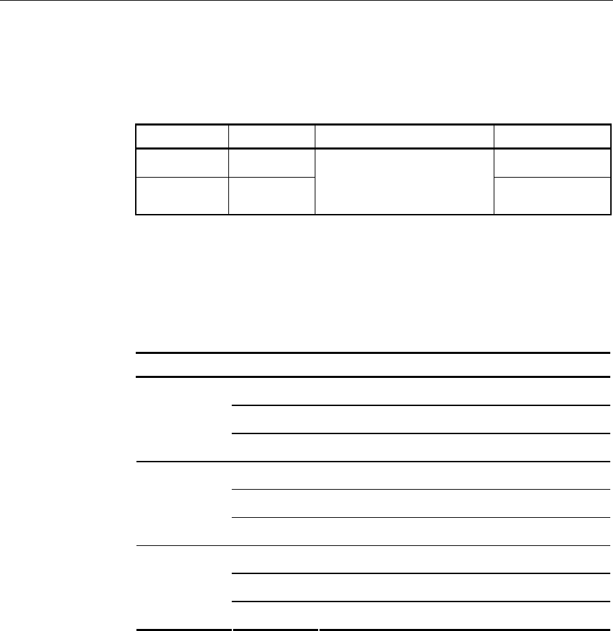
Power Receptacle
The following table provides information about the CBS power
receptacle.
Pins Description Connection Belden Wire Color
1, 3, 5, 7, 9 +48 VDC White
2, 4, 6, 8, 10 Ground
From CBS power
supply to primary CBS,
and CBS to CBS Black
CBS Status Lights
The Ethernet status lights (LEDs) are in the top corners of the data
connectors. The Power status light is a red LED shown to the right of
the power receptacle in the previous illustration.
The CBS status lights indicate the following conditions.
LED State Meaning
On OK (power is on)
Off PROBLEM (no power)
Power (red)
Blinking PROBLEM (intermittent power)
On OK (good link)
Off PROBLEM (no link)
C (green)
Ethernet
link status Blinking PROBLEM (intermittent link)
On NOT DEFINED
Off PROBLEM (no receive activity)
D (yellow)
Ethernet
activity Blinking OK (receive activity)
Chapter 2: Installing the Hardware Infrastructure 2-19
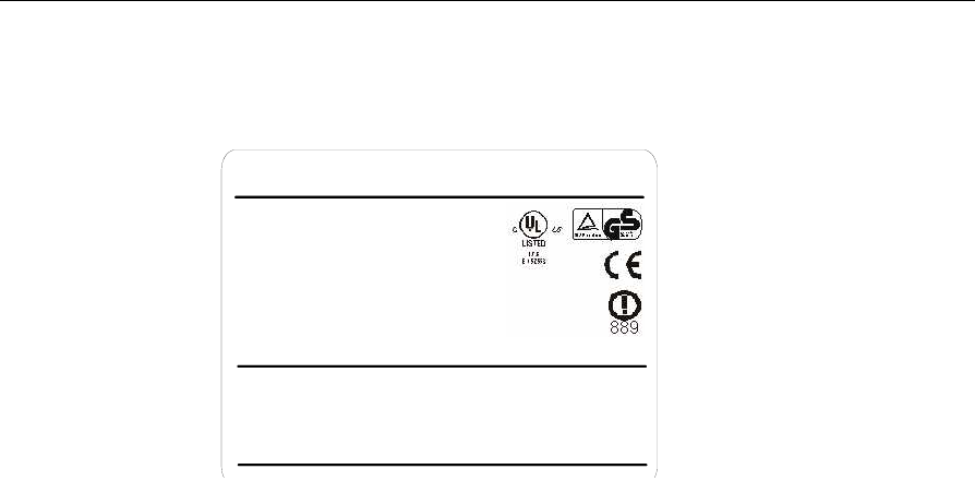
CBS Identification
NCR Corporation Made in U.S.A
Class
Model:
(Part of Class
Part Number:
Date of Mfg:
Serial #:
MAC Address:
48 VDC 0.4A
7730
2011-9090
7730 ESL System)
497-0423350
10/11/04
31-2345678
080001357942
21954
ONLY USE NCR MODEL 7730 48V POWER SUPPLY
Patents:5 640 683, 5 604 923
The CBS product label identifies the model number, serial number, and
unique MAC address of the CBS. The least significant 6 hexadecimal
characters of the MAC address are used to specify the host name for
each CBS in the CBS Manager section of the RealPrice CBS
Configuration file (DNCBSCONFIG.XML). The host name format is
NCRDNETXXXXXX where XXXXXX represents the 6 characters from
the MAC address (357942 for the sample label above).
When you complete the RF infrastructure installation, you need to
assign IP addresses and verify CBS communications. The
recommended method for managing IP addresses is through the use of
Static IP Addressing. A DHCP Manager from a DHCP Server may also
be used. Refer to “Chapter 4: CBS Configuration” in the RealPrice
Software Guide (B005-0000-1479) for details about assigning CBS
addresses in your Ethernet network and also how to enter the CBS
configuration information in the CBS Configuration File. Refer to the
"Verify Communication Links" section for how to verify CBS
communications.
2-20 Chapter 2: Installing the Hardware Infrastructure
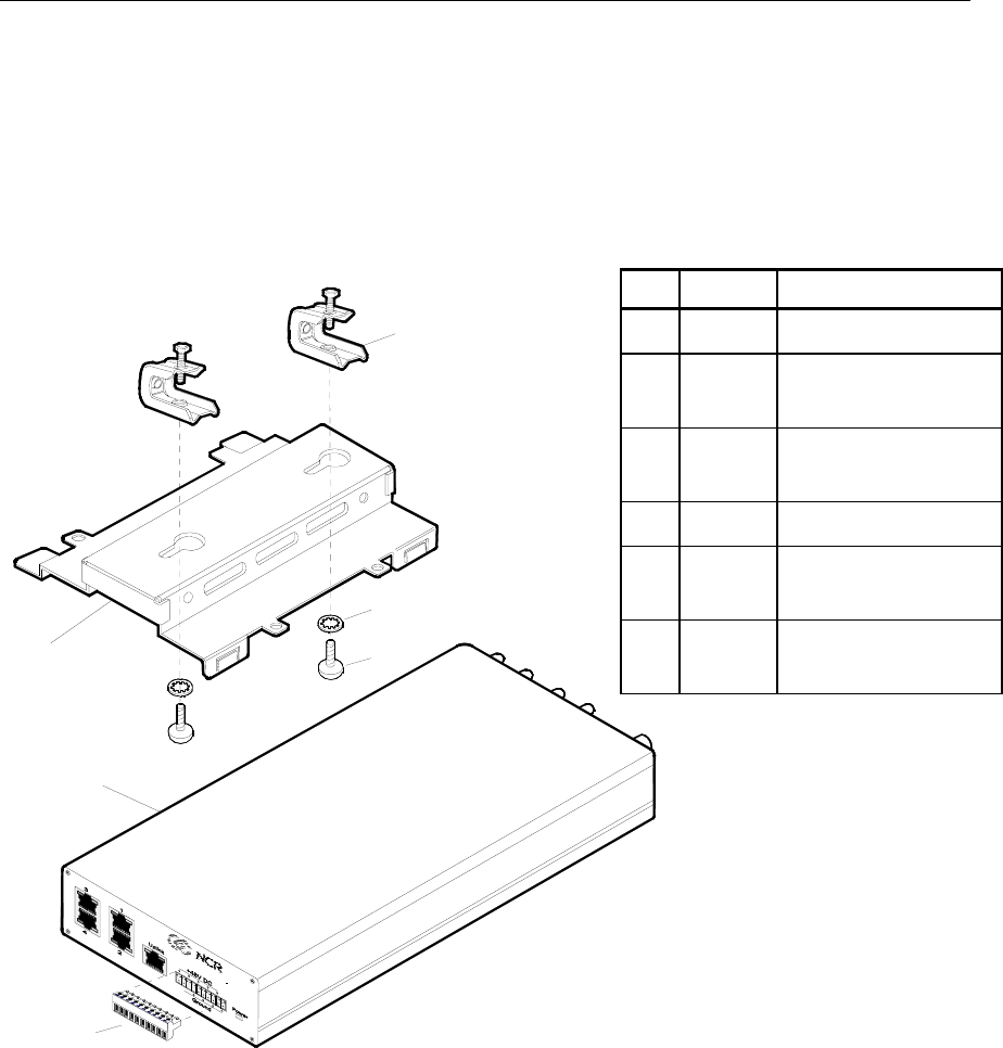
CBS Installation
Install the CBSs at the same time you install the power cables, data
cables, and antennas. The most efficient way to install the RealPrice
hardware is in one pass through the store.
The following table and illustration show a CBS and the mounting
hardware shipped with the CBS.
1
2
4
5
3
621394
Item Quantity Description
1 1 CBS
2 1 CBS mounting
bracket
3 2 Universal beam
clamp
4 2 Lock washer
5 2 Screw (¼ -20 x ¼
Phillips head)
6 1 Power connector
(installed on CBS )
Chapter 2: Installing the Hardware Infrastructure 2-21
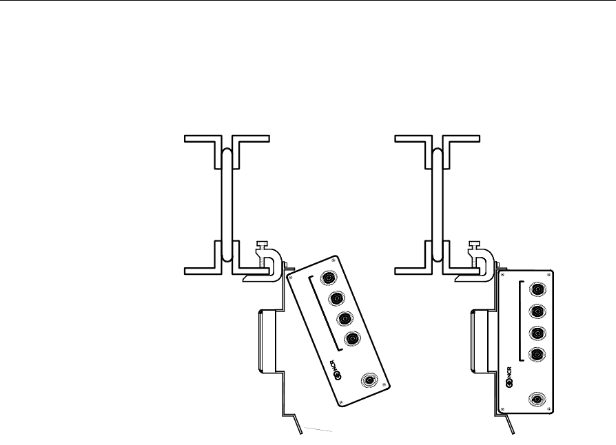
The CBS can be mounted in any position. The mounting bracket and
universal beam clamps permit a wide variety of installations. Position
the CBS for easy LED and connector access. The following illustrations
show a CBS mounted to a roof truss.
Step 1.
21392
Step 2.
Mounting Bracket Tabs
ABCD
Transmit
Receive
ABCD
Transmit
Receive
ABCD
Transmit
Receive
ABCD
Transmit
Receive
Warning: The CBS must be mounted securely and installed in
accordance with local building codes. The mounting surface must be
able to withstand a minimum weight of 2.26 kg (5 lb.).
Caution: DO NOT install a CBS by placing it on a ceiling tile.
The following procedure describes the installation of a CBS to a roof
truss as shown in the previous illustration.
1. Attach the CBS mounting bracket to the universal beam clamp
using the Phillips head screws and the tabs on the side of the CBS
mounting bracket.
Caution: Vibrations can loosen the screws holding the mounting
bracket to the clamps. It is extremely important to place the lock
washers on the screws before installing the screws into the clamps.
2. Attach the clamp to the beam.
2-22 Chapter 2: Installing the Hardware Infrastructure
3. Insert the CBS as shown in Step 1 and Step 2 of the illustration.
Make sure CBS is latched by the mounting bracket tabs.
Note: Press the mounting bracket tabs to remove a CBS from the
mounting bracket.
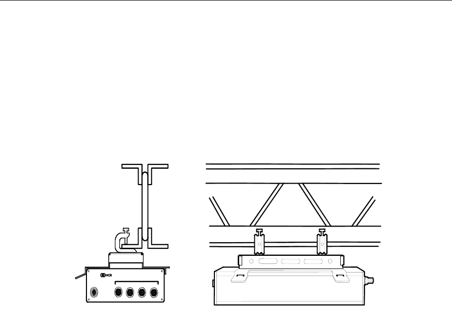
Alternate CBS Mounting Solution
21397
ABCD
Transmit
Receive
ABCD
Transmit
Receive
Connecting Ethernet Data Cables
From the primary CBS, a data cable connects every secondary CBS in
the system as shown previously in “CBS Ethernet Cable Connections”
section. Note that the Uplink data connector is used to connect to a
higher level CBS and the data connectors 1, 2, 3, and 4 are used to
connect to lower level CBSs. Otherwise, use standard CAT5 Ethernet
wiring conventions.
General Comments Regarding Ethernet Wiring
In this section, the assumption is that RJ45 connectors are being
crimped directly to the ends of each cable. It is acceptable to use punch-
down jacks and pre-fabricated CAT5 patch cables, or any other
generally accepted CAT5 wiring methodology.
Chapter 2: Installing the Hardware Infrastructure 2-23
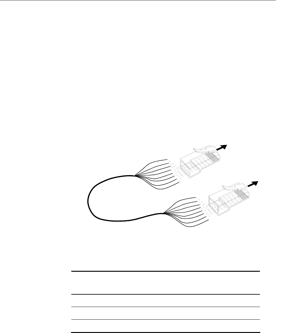
Connecting the Ethernet Hub to the Primary CBS
Each store configuration has only one primary CBS. All other CBSs are
secondary CBSs. The primary CBS is connected directly to the Ethernet
Hub. Standard 4 pair, CAT5, 24 AWG solid, unshielded cables are
required for all Ethernet communications.
Locate the Ethernet hub.
1. Cut a length of data cable that is long enough to reach from the hub
to the primary CBS. Refer to "General Layout Instructions" section
for maximum cable length information.
2. On each end of the data cable, install the wires into an RJ45
connector as shown in the following illustration and then crimp the
connector onto the cable.
18959
To Ethernet Hub
or CBS III Hub
To CBS III
Hub
RJ45
Connector
Blue/White
Orange
Orange\White
Green
RJ45
Connector
8
1
1
8
Note: Colors shown are for recommended Belden
cables. Your wire colors may be different.
Blue/White
Orange
Orange\White
Green
Blue
Blue
Green/White
Green/White
Brown
Brown
Brown/White
Brown/White
Belden Wire Colors
RJ45 Pin Color RJ45 Pin Color
1 Orange 5 Blue
2 Orange/White 6 Green/White
3 Green 7 Brown
4 Blue/White 8 Brown/White

2-24 Chapter 2: Installing the Hardware Infrastructure
3. Plug the data cable into the Uplink data connector on the primary
CBS.
Connecting Secondary CBSs
Follow these steps to connect the secondary CBSs:
1. Cut a length of data cable that is long enough to reach from one
CBS to the next CBS.
2. On each end of the data cable, install the wires into an RJ45
connector as shown in the previous illustration and then crimp the
connector onto the cable.
3. Plug the RJ45 connector into data connector 1, 2, 3, or 4 and into the
Uplink data connector of the next CBS.
4. Repeat steps 1 – 3 until all secondary CBSs are linked by a data
cable.
Connecting Power Supply Cables
Refer to the illustrations in the “CBS Power Supply Cable Connections”
section. Power supply cable routing is store dependent. The power
connector provides flexibility to connect additional CBSs in series from
one CBS to another or in parallel from a CBS to four other CBSs.
Connecting CBS Power Supplies to AC Power
Place the CBS power supplies with the host computer system, if
possible. Plug all power supplies into a common power strip so that
they can be powered on and off at the same time for reset purposes.
AC main power strips must have an indicator light to prevent
confusion about whether the system is currently powered on or off.
DO NOT remove power by unplugging the +48 VDC plug from the
power supply or the CBS as this may cause damage to the CBS.

Chapter 2: Installing the Hardware Infrastructure 2-25
Cable length restrictions may prevent installing all power supplies in
the same location. In this case, it may be necessary to install a
separately switched AC main circuit so that the power supplies can
still be controlled at the same time. If local electrical codes or special
circumstances require the installation of more than one switched AC
main circuit for the power supplies, all the main circuit switches
should be in the same easily accessible location.
Do not install the CBS power supply in the ceiling.
1. Have an electrician install new AC receptacles if needed.
2. Do not plug the CBS power supply into an AC receptacle until
steps 1 – 6 in the next section are complete and the transmit
antenna is connected to the CBS.
Connecting CBS Power Supplies to CBSs
Each CBS power supply can power up to five CBSs as shown
previously in the store configuration illustration. The wiring is the
same for each group of up to five CBSs.
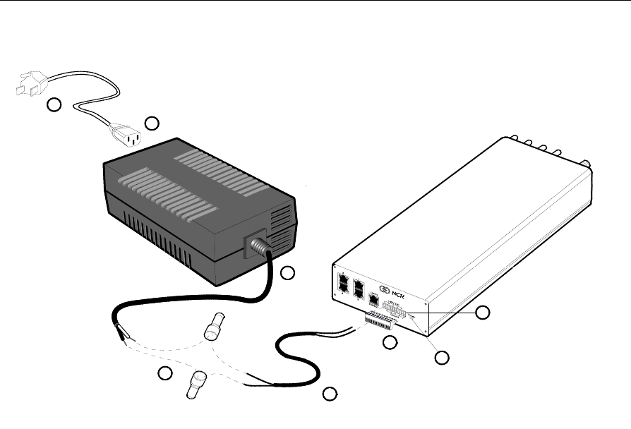
Follow these steps to connect a CBS power supply to each group of up
to three CBSs:
1. Cut a length of power cable that is long enough to reach from the
power supply to a CBS.
2. Splice the power cable wires to the pigtail supplied with the power
supply (black to black and red to white) and then crimp the
provided crimp connectors over the splices.
2-26 Chapter 2: Installing the Hardware Infrastructure
21398
5
White
White
Black
Black
2
1
3
White
Black
Note: Colors shown are for recommended Belden
cables. Your wire colors may be different.
7
8
4
6
21953
3
3. Plug the connector into the power supply.
4. On the CBS, unplug the power connector.
5. Install the power cable wires into the connector (white into pin 1, 3,
5, 7 or 9 [48 V] and black into pin 2, 4, 6, 8 or 10 [Ground]). Use
pins in pairs: 1-2, 3-4, 5-6, 7-8, and 9-10 for each power cable
connection at the CBS.
6. Plug the connector back into the CBS.
7. Insert the AC power cable into the power supply's AC receptacle.
8. Connect the AC plug to the AC power source.
9. Turn on AC power by setting switch to ON position. (Green light
indicates that power source is working properly).
Caution: To prevent damage to the transmitter, the transmit antenna
must be connected to the CBS before applying power to the CBS.
Chapter 2: Installing the Hardware Infrastructure 2-27
CBS Antennas
Two types of antennas are available:
• Transmit
• Receive
The transmit and receive antennas look similar, but have the following
differences:
• The transmit antenna has a small blue dot on the antenna case.
• The transmit antenna has a 1.83 m (6 ft.) cable attached. The cable
has a threaded reverse polarity TNC connector that attaches to the
CBS.
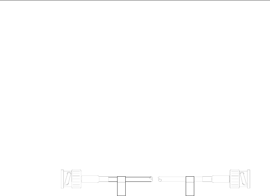
• The receive antenna has a 0.25 m (10 in.) cable attached. The cable
has a female BNC connector. A CBS Receive Antenna cable (1424-
C057-0180) is used between the attached cable and the CBS. This
cable has two BNC connectors.
14086
Note: The new Antenna cable for Freezers is 6 meters (19 feet) long.
Note: With 100 mW CBSs, a 15 m (49 ft.) receive antenna cable
1416-C520-0150 must be used instead of the usual 18 m (59 ft.) receive
antenna cable.
Consider the following when installing antennas:
• Install the antennas at the same time that the CBSs are installed.
• When connecting cables to antennas (especially Transmit
antennas), make sure connections on both ends are properly
aligned on the threads and are screwed down completely.
• Use care when connecting cables so the antenna cable connector is
not loosened from the circuit board inside the antenna.

2-28 Chapter 2: Installing the Hardware Infrastructure
• On a suspended ceiling, mount the antennas to the ceiling tile. In an
open ceiling, hang the antennas from the roof trusses.
• When mounting the antenna, face the front of the antenna (the side
opposite the cable connector) towards the ESLs, with as few
obstructions between it and the ESLs as possible.
Caution: The transmit antenna is required to comply with FCC RF
exposure requirements for mobile transmitting devices. A separation of
20 cm (8 inches) or more must be maintained between the antenna and
all persons during device operation to satisfy RF exposure compliance.
Installing CBS Antennas
The transmit antenna and receive antenna kits include the same
mounting hardware. The installation procedures for the transmit and
receive antennas are the same.
Note: Observe the following precautions to avoid RX antenna ESD
failures:
1. Always connect the RX cable to the CBS before connecting the cable
to an RX antenna.
2. Keep antennas in their anti-static packing bags until they are ready
to be installed.
3. Before handling, installing, or removing an RX antenna, touch a
grounded metal surface.
4. Only trust antennas that arrive in silver-gray plastic bags with anti-
static warning stickers.
5. If using a lift truck, ensure that it has an anti-static ground drag
strap. If it does not, then drag a short length of metal chain from the
lift truck undercarriage to dissipate any static energy.
Chapter 2: Installing the Hardware Infrastructure 2-29
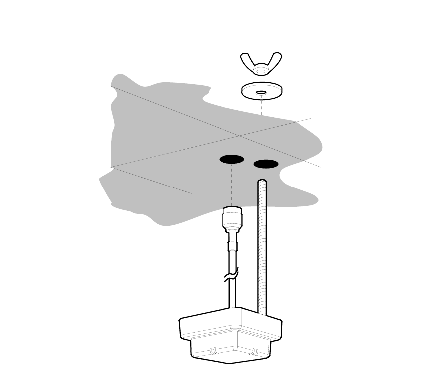
Mounting an Antenna to a Suspended Ceiling
20354
Suspended
Ceiling
Note: Maintain a minimum distance of 9.2 m (30 ft.) between a 1 W or
500 mW CBS's transmit and receive antennas. Minimum distance for a
100 mW CBS's transmit and receive antennas is 6.1 m (20 ft.).
To install an antenna on a suspended ceiling:
1. At the desired location, make two (2) 16 mm (5/8 in.) holes in the
ceiling tile using the template provided with the antenna kit.
Note: Make sure debris from the ceiling tile does not fall into the
antenna connector.

2-30 Chapter 2: Installing the Hardware Infrastructure
2. Screw the 63.5 mm (2.5 in.) antenna stud into the 1/4-20 UNC hole
in the back of the antenna.
3. Route the antenna cable through one hole in the ceiling tile and the
antenna stud through the other hole.
4. Place the 31.75 mm (1.25 in.) fender washer on the antenna stud
and screw the 6.35 mm (0.25 in.) wing nut onto antenna stud until it
firmly holds the antenna against the ceiling tile.
5. Connect the antenna cable as follows:
• Transmit antenna - Attach the 1.83 m (6 ft.) Transmit antenna
cable to the CBS.
• Receive antenna - Connect one end of the Receive antenna cable
to the CBS. Attach the Receive antenna pigtail to the other end
of the Receive antenna cable.
6. Use cable ties to secure the antenna cable.
Chapter 2: Installing the Hardware Infrastructure 2-31
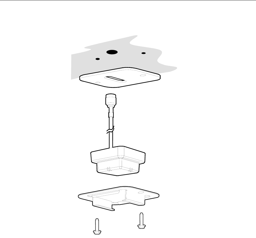
Mounting an Antenna in a Freezer
20355
Freezer Bracket
Freezer Gasket
7730 RealPrice CBS freezer layout guidelines sometimes require
mounting receive (RX) antennas inside of freezers. To prevent
mechanical and moisture damage to the antenna or freezer, use the
following installation guidelines:
• Seal all cable entry holes with permagum sealing compound. Do
not use expanding foam.

2-32 Chapter 2: Installing the Hardware Infrastructure
• If the customer stacks merchandise on top of the freezers, protect
exposed RX antenna cables with metal conduit.
• Protect the RX antenna BNC cable connector from the freezer
environment.
Note: Maintain a minimum distance of 9.2 m (30 ft.) between each 1 W
or 500 mW CBS's transmit and any receive antennas. Minimum
distance for a 100 mW CBS's transmit and receive antennas is 6.1 m (20
ft.).
To install an antenna in a freezer:
1. At the desired location, drill one (1) 16 mm (5/8 in.) hole for the
antenna cable.
2. Route the antenna cable through the hole in the Freezer Gasket.
3. Place the Freezer Bracket over the Antenna and check the
alignment of the assembled parts as follows.
Note: The round and elongated mounting holes in the gasket and
bracket are matched together.
• The antenna alignment guides are centered between the edges of
the elongated hole in the gasket.
• The gasket does not extend past the edge of bracket on any side.
Note: Proper alignment of gasket, antenna, and bracket is necessary to
make a secure seal against the ceiling.
4. Route the antenna cable through the hole in the ceiling.
5. Raise the assembled parts up against the ceiling.
6. Using the Freezer Bracket as a template, drill two (2) 3 mm (0.125
in.) holes in the freezer ceiling for the mounting screws.
7. Use the two (2) self-tapping screws to secure the bracket to the
ceiling.

Chapter 2: Installing the Hardware Infrastructure 2-33
8. Connect the end of the Receive antenna cable to the CBS, then
attach the Receive antenna pigtail to a Receive Antenna Cable.
Connect the other end of the Receive antenna cable to the CBS.
Note: Protect the RX antenna BNC cable connector from the freezer
environment.
• Water condensation inside and dripping water from outside an
unprotected BNC connector will trigger electrolytic corrosion
that will eventually destroy the connector.
• Carefully choose freezer RX antenna locations so that the inline
BNC cable connectors are in a room temperature environment
outside the freezer wall.
• For conventional stand-alone freezers, use the 7730-K050-V003
"Kit - Rx Antenna w/18m cable" or 7730-K054-V003 "Kit - Rx
Antenna w/15m Cable (for 100mW CBS)." These antennas
have a 25cm (10inch) antenna lead.
• For large walk-in and oversized freezers with high ceilings, use
the new long-lead 7730-K055-V002 "Kit - Rx antenna (6m lead)
and 12m cable." These antennas have an extended 6m (20ft)
antenna lead for better freezer routing, but they must be used
with the corresponding shortened 12m (39ft) antenna cable for
proper operation.
• In special situations, it is possible to seal the inline BNC
connector from the freezer environment. See the detailed
instructions below.
9. Use cable ties to secure the antenna cable.
10. Seal all cable entry holes with permagum sealing compound.
• Unsealed holes will cause icicles around entry holes and frost
buildup on nearby product. If the inline BNC connector is not
protected, condensation will drip down the antenna cable and
trigger electrolytic corrosion inside the connector that will
quickly destroy it.

2-34 Chapter 2: Installing the Hardware Infrastructure
• To use permagum, roll a walnut-sized piece into a rope shape
and push as much as possible into both ends of the cable entry
hole. Permagum-type sealing compound looks like modeling
clay and is commonly available from HVAC and electrical
supply houses. One example is Virginia KMP brand sealing
gum, catalog number PP-22V, from www.virginiakmp.com.
• If replacing an antenna or cable, re-seal the cable entry hole.
New permagum is best, but existing permagum can be re-used,
if necessary.
• DO NOT use any type of expanding foam sealant, for example
Dow brand "GREAT STUFF" polyurethane foam or DAP brand
DAPtex latex foam. NCR has found that these materials do not
cure properly at freezer temperatures or in the presence of
water condensation.
Note: If the customer stacks merchandise on top of the freezers,
protect exposed RX antenna cables with metal conduit. Customers
sometimes showcase large items on top of freezer units. These items
will damage exposed RX antenna cables. Protect cables with short
lengths of metal or plastic electrical conduit. Use appropriate straps to
keep the conduit in place.
Special Instructions for Sealing Inline BNC Antenna Connectors That
Must Be Located Inside Freezers
This BNC sealing procedure is only recommended for the following
situations:
• If servicing a walk-in or oversized freezer that was installed before
the previous guidelines were available
• If installing RealPrice infrastructure at a new site and long-lead RX
antenna kit 7730-K055-V002 cannot be obtained in time to meet the
installation schedule

Chapter 2: Installing the Hardware Infrastructure 2-35
Materials Required:
• 12in (30.5cm) length of CoaxSeal™ #105 hand-moldable plastic
material (http://www.coax-seal.com). This material is available
from Radio Shack and commercial electrical supply houses.
• 12in (30.5cm) length of black electrical tape, 3M Super 88 Scotch®
Brand Vinyl Electrical Tape or equivalent
Procedure:
1. Connect the RX antenna to the RX cable inside the freezer.
2. Wrap the in-line connectors with electrical tape. The electrical tape
allows the Coax-Seal™ material to come off cleanly in case of future
servicing.
3. Wrap the connection with a 12in (30.5cm) length of Coax-Seal™
material. Wrap beyond the ends of the electrical tape in order to
ensure a watertight seal.
4. Shape and form the Coax-Seal™ material to ensure a good seal.
Note: Keep the electrical tape and Coax-Seal™ material warm inside a
jacket as much as possible while working in the freezer. This keeps
them flexible for better adhesion.
Note: To prevent condensation from becoming trapped inside the
cable connection, do not remove antennas or cables from the freezer
once they have become cold. If they are removed, then keep them
outside the freezer until all signs of condensation have evaporated
before bringing them back in.

2-36 Chapter 2: Installing the Hardware Infrastructure
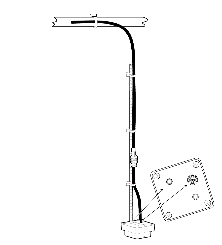
Hanging an Antenna from a Roof Truss
Note: Maintain a minimum distance of 9.2 m (30 ft.) between a 1 W or
500 mW CBS's transmit and receive antennas. Minimum distance for a
100 mW CBS's transmit and receive antennas is 6.1 m (20 ft.).
To hang an antenna from a roof truss (or other object) refer to the
illustration on the following page and these instructions:
1. Screw the 0.61 m (2 ft.) threaded rod into the 1/4-20 UNC hole in
the back of the antenna.
Note: A 2 ft. threaded rod is supplied in the antenna kit. If the open
ceiling installation requires a longer section of threaded rod, it is
expected the requirement be pre-determined and the longer rod be
supplied by the installer.
2. Secure the antenna cable to the threaded rod using three equally
spaced cable ties.
Note: Attach the 0.25 m (10 in.) Receive antenna pigtail to a Receive
Antenna Cable before securing the cable to the threaded rod as shown
in the illustration.
3. In the desired location, hold the antenna cable against a roof truss
and lower the antenna to the desired height.
4. Use a cable tie to hang the antenna cable from the roof truss.
Caution: Antenna cables must be secured to a roof truss as shown in
the following illustration. Do not hang the antenna from a CBS's
connector as the connector cannot withstand the weight of the
threaded rod, cable, and antenna.
5. Connect the antenna cable to the CBS.
Note: Always connect the RX cable to the CBS before connecting the
cable to an RX antenna.
6. Use cable ties to secure the antenna cable.
Chapter 2: Installing the Hardware Infrastructure 2-37
1/4-20 UNC
M6 X 1
20351
Open Ceiling

2-38 Chapter 2: Installing the Hardware Infrastructure
CBS Hardware Configuration
After all RF infrastructure components have been installed, and the
Ethernet cabling and power supply cabling has been circuit tested for
continuity, the system can be powered-up to establish the connection
between an Ethernet network and the RealPrice CBS units. IP allocation
can be configured using Static IP Addressing or using a DHCP Server.
Static IP addressing may be required for the following situations.
• For permanent assignment when you are not able to use the
existing DHCP Server/DHCP Manager in your communication
network
• For permanent assignment when you do not have a DHCP
Server/DHCP Manager in your communication network and
customer does not wish to have one
• For temporary assignment of IP addresses to test the RF
infrastructure
The decision is made during site survey interviews between the PS
Project Manager and the customer. The IP addresses, subnet mask, and
gateway address are provided by the customer’s IT support group.
Refer to the “Chapter 4: CBS Configuration” in the RealPrice Software
Guide (B005-0000-1479) for details about how to configure the IP
addresses for the RealPrice CBS units.
Verify Communication Links
Use the following procedures to verify your communication links.
1. Power-up each CBS.
2. Verify that each CBS link status LED is lit.
3. Use the Ping utility to ping each CBS using its IP Address to verify
connectivity.

Chapter 2: Installing the Hardware Infrastructure 2-39
Note: If your network is using a Dynamic IP Addressing, use the ARP
utility to display a list of the dynamically assigned IP Addresses. Refer
to “Chapter 4: Common Diagnostic Utilities” in the RealPrice Utilities
Guide (B005-0000-1487) for details on ARP. Cross reference the CBS
MAC address to the CBS number assigned in the store layout to
confirm all CBSs respond to the ping test. If reserved IP addresses were
used, refer to that list to confirm all CBSs respond to the ping test.
Document CBS Network Addressing
Note the CBS Numbers, MAC Addresses, and CBS IP Addresses on the
store layout for reference purposes.
RealPrice Software Installation, Configuration, and Testing
After the CBS hardware network is verified and you have documented
the CBS network addressing information, the next steps are to install
RealPrice Software, modify the RealPrice CBS Configuration file, and
validate RealPrice System functionality. The following sections identify
where to find details to accomplish these steps.
• Installing RealPrice Software
Refer to “Chapter 2: Installing RealPrice for Windows Software” or
“Chapter 3: Installing RealPrice for AIX Software” in the RealPrice
Software Guide for details.
• Modifying the CBS Configuration File
Refer to “Chapter 4: CBS Configuration” in the RealPrice Software Guide
(B005-0000-1479).
• Verifying Hardware and Software Configuration
For RealPrice for Windows NT/2000/XP systems, refer to “Chapter 2:
The RealPrice Support Utility” in the RealPrice Utilities Guide (B005-
0000-1487).
• View the CBS network addresses.

2-40 Chapter 2: Installing the Hardware Infrastructure
• View and, if necessary, set CBS Timeslots and the Frequency
Hopping Table.
For RealPrice for AIX systems, refer to “Chapter 5: Testing and
Troubleshooting” in the RealPrice Installation and Service Guide (B005-
0000-1247).
• Use the dnutils utility to view the CBS network addresses.
• Use the dnutils utility to view and, if necessary, set CBS Timeslots
and the Frequency Hopping Table.
• In Windows NT/2000/XP and AIX environments use dncalib to
display CBS ID and RSSI readings on a single ESL while standing
under each CBS receive antenna to verify all CBS units are
communicating properly. Refer to “Chapter 4: Common Diagnostic
Utilities” in the RealPrice Utilities Guide (B005-0000-1487).
Note: dncalib must be run in Install mode for this test.
• Upgrade all CBS firmware to the latest version available. The latest
firmware release can be found at www.ncr.com -> support ->
drivers and patches -> retail support files -> RealPrice support
files
Note: Check to make sure that the customer does not have a special
firmware version requirement.
Caution: Some customers may not allow firmware to be installed
until it has been integration tested.
• After RealPrice Base software and the custom integration software
is installed, use the Data Reader test to check the status of the
RealPrice data reader and verify ESL display data to confirm the
data reader is functioning properly. Refer to the “Software
Diagnostics” section in “Chapter 2: The RealPrice Support Utility”
in the RealPrice Utilities Guide (B005-0000-1487) for details.

Chapter 3: Maintenance
Replacing RealPrice Hardware
Except for the ESL battery replacement described in this chapter, the
RealPrice System hardware does not require any preventive
maintenance. If there is a problem, trained NCR Customer Service
personnel or other trained personnel can use the diagnostics and
troubleshooting information in the RealPrice Utilities Guide (B005-0000-
1487) to analyze and isolate the problem.
RealPrice hardware is not field-repairable. If it is determined that a
CBS, antenna, power supply, or ESL is defective, use the procedures
described in this chapter to replace the unit with a new one. If
appropriate, contact your NCR representative for information on
where to send the defective unit for repair.
Important Information: After removing or replacing the CBS or a
transmit antenna, it is recommended that RF communications be re-
certified. It is also recommended that the change in the site
configuration be noted for support purposes. For more information,
contact your NCR representative and reference the following:
• RealPrice Implementation Guide (B005-0000-1250)
• RealPrice RF Certification Utility Guide (AIP-000269)
• RealPrice Certification Site Survey Policy (497-0421218)

3-2 Chapter 3: Maintenance
Windows 2000/NT/XP and AIX Environment Procedures
The component replacement sections in this chapter provide steps that
can be followed for RealPrice installations in Windows 2000, Windows
NT, Windows XP, and AIX UNIX environments. However, the
procedures to stop and start the RealPrice System software are
different for Windows and AIX installations. Also, the CBS Support
Utility (dnutils.exe) shipped with the RealPrice Base Software for
Windows NT/2000/XP and the CBS Setup utility (dncbssetup.exe) in
RealPrice for AIX Release 3.1 have different procedures to access the
functions available in each utility. This section identifies the
environment-specific differences to use when replacing RealPrice
hardware components.
Stopping and Starting RealPrice Using the Start Button
• Stop the RealPrice System software by clicking on the Start button
and selecting Programs > RealPrice> Stop RealPrice Applications.
• Start the RealPrice System software by clicking on the Start button
and selecting Programs > RealPrice > Start RealPrice
Applications.
Stopping and Starting at a System Prompt
The following commands can be used in Windows 2000. Windows NT,
and Windows XP at a DOS prompt and in AIX at the AIX UNIX
prompt.
• To stop RealPrice, enter the following command:
stopdn
• To start RealPrice, enter the following command:
startdn

Chapter 3: Maintenance 3-3
RealPrice Support Utility
Note: Refer to the Chapter 2: The RealPrice Support Utility in the
RealPrice Utilities Guide (B005-0000-1487) for details on using this
utility.
• In a Windows NT/2000/XP environment, start the RealPrice
Support Utility by entering the following command at a DOS
system prompt.
dnutils
• Select the following options to Enable Normal Mode
communications:
11. CBS Setup > 51. Set Communications Mode > 1. Normal Mode
• Select the following options to View/Set Timeslots
11. CBS Setup > 13. Timeslot IDs
• Select the following options to View/Set Frequency Hopping Table
entries
11. CBS Setup > 16. Hopping Tables
• Select the following options to View Diagnostics
11. CBS Setup > 44. View Diagnostics
RealPrice for AIX CBS Setup Utility
Note: Refer to the “dncbssetup (CBS Setup Utility)” section in
“Chapter 7: Diagnostics and Troubleshooting” of the RealPrice
Installation and Service Guide (B005-0000-1247) for details on using this
utility.
• In a Windows AIX environment, start the CBS Setup utility by
entering the following command at an AIX system prompt.

3-4 Chapter 3: Maintenance
dncbssetup
• Enable Normal Mode communications by selecting option 51. Set
Communication Mode in the Operations section on the main menu.
• View/Set Timeslots by selecting option 13. Timeslot IDs in the Setup
section on the main menu.
• View/Set Frequency Hopping Table entries by selecting option 16.
Hopping Tables in the Setup section on the main menu.
• View Diagnostics by selecting option 43. View Diagnostics in the
Diagnostics & Tallies section on the main menu.
Replacing a CBS
Use this procedure to replace a malfunctioning CBS with another one.
1. Obtain the CBS Timeslots for the CBS being replaced. Look in the
dncbsstatus.out file for the site or get them from the Site
Installation documents. This information is needed in Step 9 below
to prevent coverage problems.
2. Stop the RealPrice System software.
3. Power off all CBSs in the system.
4. Disconnect antennas, power cable, and Ethernet cable(s) and
remove the malfunctioning CBS.
5. Install the new CBS and reconnect the cables.
Note: If a 3.2 CBS is to be replaced with a 3.4 CBS, all of the power
cables must be disconnected from the 8-pin connector and reconnected
to the new 10-pin connector. The 3.4 CBS is backwards compatible.
Caution: The 3.2 CBS is not compatible with a 3.4 Power Supply.
Doing so will destroy the CBS.
6. Power up all CBSs in the system.
7. Set the IP address for the new CBS.
• If using static IP addressing – use the Setup CBS option in
RealPrice Support Utility to assign the IP address to the CBS
(MAC address)

Chapter 3: Maintenance 3-5
• If using DHCP – change reservation so new MAC address is
reflected
8. Start the RealPrice System software.
9. Use the RealPrice Support Utility or CBS Setup utility to set the
CBS Timeslots and verify the Frequency Hopping Table does not
conflict with the existing CBSs.
10. Check the Diagnostics information for the new CBS using the
RealPrice Support Utility or CBS Setup utility.
• Make changes to firmware, if mismatch – before upgrading any
CBS, read firmware release notes
• Verify Country Codes match
• Check Transmit Power Levels
• Not 0 (zero)
• Within a range of +/- 10
11. Use the dncalib utility to verify CBS is functioning in the coverage
area where the CBS was replaced.
12. Confirm that errors related to the replaced CBS are no longer being
logged.
13. Run dncbsstatus utility to obtain new dncbsstatus.out file.
14. Upload results of all tests and files noted above to the CKS2000 web
site.
Adding a CBS
Use this procedure when adding a CBS to an existing installation to
extend or increase the coverage area.
1. Stop the RealPrice System software.
2. Power off all the CBSs in the system by powering off the power
supplies.
3. Add Ethernet and power supply cabling to extend the existing
network.

3-6 Chapter 3: Maintenance
4. Install CBS Transmit and Receive Antenna(s), and antenna cables as
required for the new CBS.
5. Install the new CBS and connect the cables.
6. Power up all CBSs in the system.
7. Use the RealPrice Support Utility or CBS Setup utility to make the
necessary changes to the dncbsconfig.xml file to identify the
new CBS IP Address or Host Name.
8. Start the RealPrice System software.
9. Use the RealPrice Support Utility or CBS Setup utility and enable
Normal Mode communications.
10. Use the RealPrice Support Utility or CBS Setup utility to set the
CBS Timeslots and CBS Hopping Table frequencies for the new
CBS.
11. Check the Diagnostics information for the new CBS using the CBS
Configuration utility or CBS Setup utility.
12. Use the RF Certification Utility and certify the RF coverage area of
the new CBS. Refer to the RealPrice RF Certification Utility Guide
(AIP-000269) for detail.
Replacing Antennas
Replacing a Receive Antenna
Use this procedure to replace a suspected malfunctioning receive
antenna.
1. Disconnect and remove the malfunctioning receive antenna.
2. Install and re-connect the new receive antenna.
3. Use the RealPrice Support Utility or CBS Setup utility and check
the Diagnostics information for the CBS where the new antenna
was installed.
4. Use the dncalib utility to verify CBS is functioning in the coverage
area where the new antenna was replaced.

Chapter 3: Maintenance 3-7
5. Confirm that errors related to the replaced antenna are no longer
being logged.
Replacing a Transmit Antenna
Use this procedure to replace a suspected malfunctioning transmit
antenna. You MUST remove power from the CBSs during this
procedure. Removing a transmit antenna from a powered CBS can
damage the CBS transmitter circuitry.
1. Stop the RealPrice System.
2. Power off all the CBSs in the system by powering off the power
supplies.
3. Disconnect and remove the malfunctioning transmit antenna.
4. Install the new transmit antenna.
5. Power up all CBSs in the system.
6. Start the RealPrice System software.
7. Use the RealPrice Support Utility or CBS Setup utility and check
the Diagnostics information for the CBS where the new antenna
was installed.
8. Use the dncalib utility to verify CBS is functioning in the coverage
area where the new antenna was replaced.
9. Confirm that errors related to the replaced antenna are no longer
being logged.
Replacing a Power Supply
Note: The power supply for release 3.4 does not work with the
previous CBS hardware. Verify the correct power supply is being used.
Use this procedure to replace a suspected malfunctioning power
supply.
1. Stop the RealPrice System software.
2. Power off all the CBSs in the system by powering off the power
supplies.

3-8 Chapter 3: Maintenance
3. Disconnect and remove the malfunctioning power supply.
4. Install a new power supply.
5. Power up all power supplies in the system.
6. Start the RealPrice System software.
7. Check the RealPrice Support Utility or CBS Setup utility
Diagnostics information to confirm that all CBS's are running.
8. Confirm that errors related to the replaced power supply are no
longer being logged.
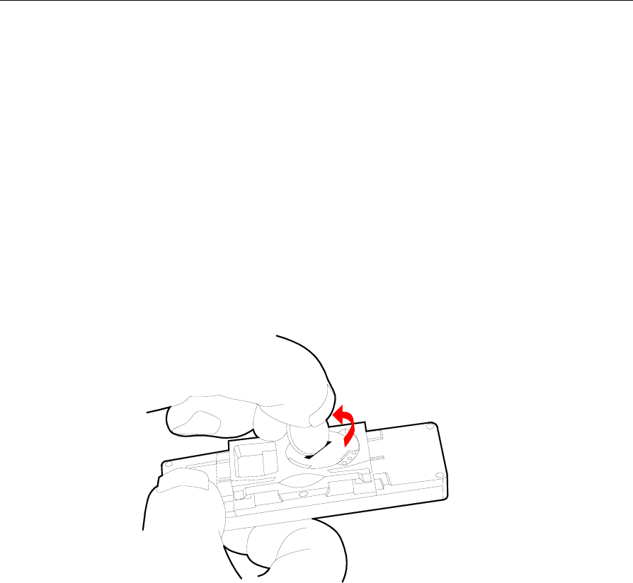
Chapter 3: Maintenance 3-9
Battery Replacement
Caution: Danger of explosion if battery is incorrectly replaced.
Replace only with same or equivalent type as recommended by the
manufacturer. Discard used batteries according to the manufacturer's
instructions.
When an ESL's battery becomes weak, the battery symbol in the
display lights indicating that its lithium battery must be replaced. After
removing the ESL from the shelf, follow these steps to replace the
batteries:
1. Open the battery cover by inserting a coin in the slot and
turning counter-clockwise to its detented position, exposing the
three holes as shown in the following illustration.
19248
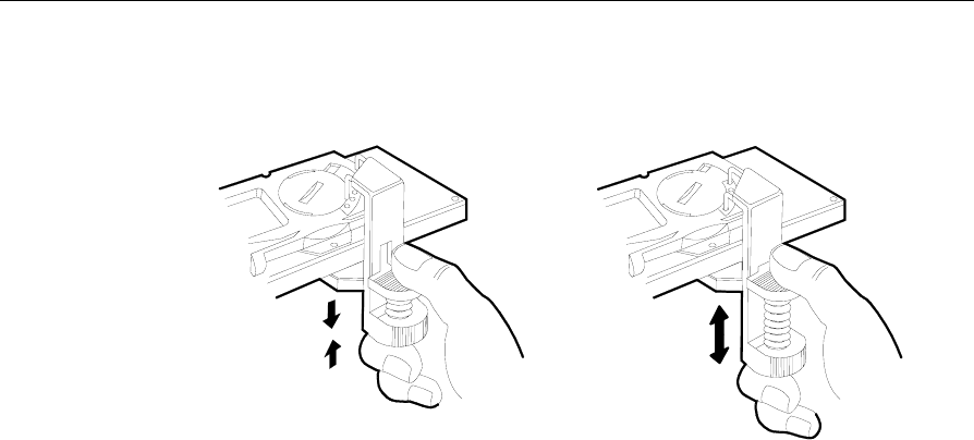
3-10 Chapter 3: Maintenance
2. Attach the Battery Replacement tool to the ESL as shown in the
following illustration.
19247
AB
3. With thumb and index finger, compress the spring to open the
clamp. Set the terminals into the first and third holes.
4. Hold pressure down on the terminals into the holes and release the
clamp until it firmly holds the ESL.
5. Remove the battery cover.
Caution: In the following steps, do not permit the battery to contact
the terminals of the Battery Replacement tool.
6. Remove the battery.
7. Place a new battery in the battery cavity.
8. Replace the battery cover.
9. Remove the Battery Replacement tool.

Chapter 3: Maintenance 3-11
Updating CBS's Firmware Image (ftpdl)
Periodically updates may be required to add enhancements or correct
problems in the CBS firmware.
Upgrade all CBS firmware to the latest version available. The latest
firmware release can be found at www.ncr.comÆSupport ÆDrivers
and PatchesÆRetail Support FilesÆRealPrice Support Files.
Note: Check to make sure that the customer does not have a special
firmware version requirement.
Caution: Some customers may not allow firmware to be installed
until it has been integration tested.
The legacy firmware update method (ftpdl) continues to be supported
for all firmware versions and is described below. To update CBS
firmware using the Firmware Bootloader, see the following topic
“Updating CBS's Firmware Image – Firmware Bootloader”.
For updates in a Windows 2000, Windows NT, or Windows XP
environment, the update file and the utility (ftpdl.exe) required to
apply the update are distributed on diskette. For updates in an AIX
UNIX environment, only the update file is distributed on diskette. The
RealPrice CBS Firmware Update utility (ftpdl) in the
/usr/local/dnet/bin directory is used to copy the update file to
the CBS firmware. The update file name identifies the version, for
example: rom109.bin. or rom310.bin in the following sections.
Caution: When updating CBS firmware, stop the RealPrice software
on the RealPrice System computer to ensure the update process is not
interrupted. If the update process is interrupted before completion, the
CBS must be returned to NCR.
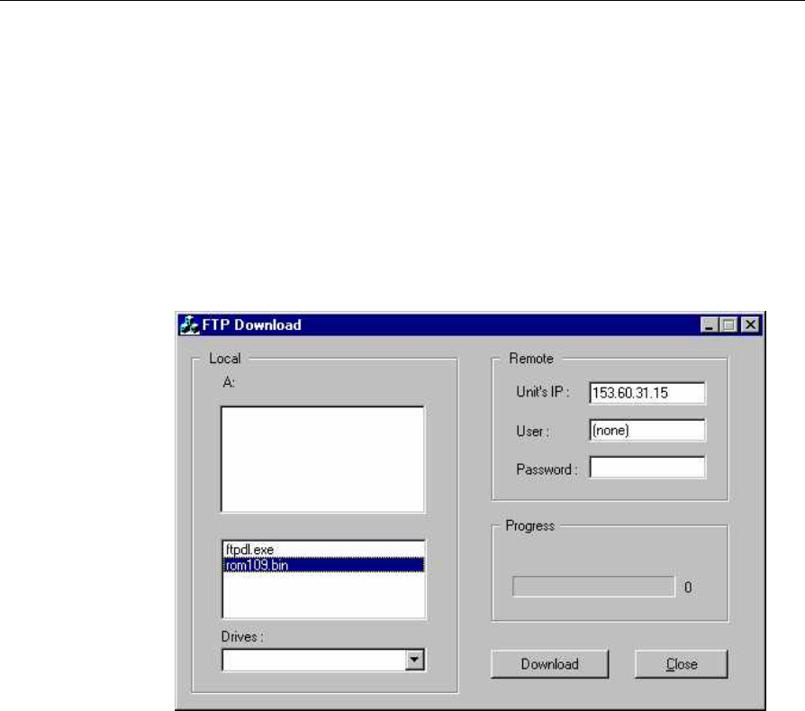
3-12 Chapter 3: Maintenance
Windows NT/2000/XP Installations
Use the following procedure to update CBS firmware in a Windows
NT, Windows 2000 or Windows XP installation.
1. Refer to the site's Installation data or use the CBS Configuration
utility to obtain the IP Addresses of all the installed CBS's.
2. Insert the update diskette in Drive A.
3. Run the ftpdl.exe program. The following screen displays.
4. In the lower section of the left-hand window (Local) highlight
the update file. In this example, rom109.bin.
5. In the upper right-hand window (Remote), enter the IP Address
of the CBS in the Unit's IP: field.
6. Click the Download button.
7. The Progress window indicates activity during the update.
8. The following screen displays when the download is complete.

Chapter 3: Maintenance 3-13
9. Click the OK button and proceed to the next step.
10. Repeat Steps 4 - 6 for each CBS in the network.
11. Re-start the RealPrice software. Select
StartÆProgramsÆRealPriceÆStart RealPrice Applications.
12. Use the RealPrice Support utility to verify all CBSs have new
firmware.
AIX UNIX Installations
Use the following procedure to update CBS firmware in an AIX UNIX
installation.
1. Refer to the site's Installation data or use the CBS Configuration
utility to obtain the IP Addresses of all the installed CBS's.
2. Insert the update diskette in Drive A.
3. Enter the following commands at the Unix prompt.
cd /tmp
dosread ROMxxx.BIN > ROMxxx.BIN
where ROMxxx.BIN is the name of the update file (such as
ROM310.bin).
4. Enter the following command at the Unix prompt.
ftpdl ROMxxx.BIN xxx.xx.xx.xxx
where:
ROMxxx.BIN is the name of the update file (such as ROM310.bin)

3-14 Chapter 3: Maintenance
xxx.xx.xx.xxx is the IP address of the CBS that needs the
firmware update
A series of number signs (#) display to indicate update activity. The
update typically takes 1 to 1 ½ minutes to finish. The following
message displays to indicate a successful update.
CBS flashed successfully
Error Messages
The following messages may display to indicate an error condition.
Flash failed, unable to connect to
xxx.xx.xx.xxx
where xxx.xx.xx.xxx is the IP address typed when the command
was initiated.
Confirm the IP address is correct and retry the update.
Flash failed, IP address is not that of a CBS
The IP address used is valid in the network, but the component using
that address is not a RealPrice CBS unit. Confirm the IP address of the
CBS requiring new firmware and retry the update.

Chapter 3: Maintenance 3-15
Updating CBS's Firmware Image – Firmware
Bootloader
Firmware Compatibility
Firmware 3.4.0 is compatible with all currently existing hardware
versions of CBS. However, some CBS hardware/firmware
combinations are not supported due to compatibility issues. Following
is a summary of these restrictions:
7730 CBS Hardware Release CBS Identification Compatible Firmware
3.0
3.1
Serial number less than
31-36497717
All versions
“original” 3.2 Serial number greater
than or equal to 31-
36407717 and service part
number less than 497-
0435814
3.2.0 and higher
“revised” 3.2 Service part number
greater than or equal to
497-0435814
3.4.0 and higher
Note: An exact serial number break-in point for the revised CBS
hardware release 3.2 will be available at a future date.
Firmware Downgradability
Once a CBS is installed with firmware 3.2.0 or higher, it cannot be
downgraded below firmware 3.2.0 except by returning it to the factory
or by contacting NCR Level 4 support for special assistance. This is
true regardless of the CBS hardware release. The ftpdl.exe utility
reports an error and the CBS remains unaffected if downgrade is
attempted. Note that firmware 3.2.0 does not support the TFTP
bootloader feature.

3-16 Chapter 3: Maintenance
Unlike the firmware 3.2.0, 3.4.0 CBS cannot be downgraded as low as
the CBS hardware can allow in the previous chart. For example, the
original hardware release 3.2 CBS can be downgraded from firmware
3.4.0 to 3.2.0. However, ftpdl.exe reports an error and the CBS remains
unaffected if a revised hardware release 3.2 CBS is downgraded from
firmware 3.4.0 to 3.2.0. If TFTP bootload feature is used to downgrade
the firmware, the CBS ignores the bootload request and remains
unaffected.
Updating the Firmware
Periodically updates may be required to add enhancements or correct
problems in the CBS firmware.
Upgrade all CBS firmware to the latest version available. The latest
firmware release can be found at www.ncr.comÆSupport ÆDrivers
and PatchesÆRetail Support FilesÆRealPrice Support Files.
Note: Check to make sure that the customer does not have a special
firmware version requirement.
Caution: Some customers may not allow firmware to be installed
until it has been integration tested.
The 7730 Firmware Management System – “Firmware Bootloader” –
(released with firmware version 3.3.4) facilitates firmware updates to
the 7730 Communications Base Station (CBS). The Firmware
Bootloader consists of software components that reside on both the
RealPrice System Server and 7730 CBS units.
Upgrading firmware from 3.2.x and earlier to 3.3.4 requires upgrading
to firmware version 3.3.4 first using the method (ftpdl) described in the
previous section “Updating CBS's Firmware Image (ftpdl)”.
The Firmware Bootloader supports:
• Simultaneous firmware update to multiple CBS units
• CBS recovery following application block firmware corruption
• Diagnostic features to support flash update failure troubleshooting

Chapter 3: Maintenance 3-17
The Firmware Bootloader provides a simple method for updating 7730
CBS firmware. The following steps outline the method for firmware
update:
• A CBS evaluates its firmware at boot time and determines if a
firmware update is necessary. This determination is made by
sending a TFTP request for the RealPrice boot file and comparing
the internal firmware version of the CBS with the target firmware
version information contained in the boot file.
• The CBS initiates the firmware update, if necessary, by making a
TFTP request for the new firmware image.
• Upon completion of the file transfer, the CBS replaces its
application firmware with the newly acquired firmware image.
• Finally, the boot firmware transfers control to the application
firmware, and the CBS begins normal operation.
Steps for completing firmware update
1. Configure the DHCP server, if using DHCP.
This is an optional step. DHCP server configuration is discussed at
the end of this section.
2. Customize the boot file, if necessary.
Two files are required to accomplish a firmware update:
• an application image, the binary image that contains the
machine instructions for normal CBS operations. Application
images are non-editable binary files and are at least 700K bytes
in size.
• a boot file , an XML file that specifies rules and instructions for
the firmware update.
Note: A default boot file and application image is distributed with
each firmware release.

3-18 Chapter 3: Maintenance
Boot File
Boot files are small, editable XML-formatted files of 1K bytes or less
and contain the following information:
• Update instructions indexed by CBS’ current firmware revision
• Application image filenames
• Application image revision information
Boot files may contain wildcard information to select a group of
target CBS units with similar characteristics. Boot files may
stipulate a firmware upgrade to a newer revision or a downgrade
to an older revision.
The user may wish to modify the boot file to specify a different
location for the firmware image or specify new rules for the update.
The boot file may be modified with any basic text editor. A sample
boot file is shown:
<?xml version="1.0"?>
<?xml-stylesheet type="text/xsl"
href="dnbootloadconfig.xsl"?>
<!DOCTYPE rp7730 SYSTEM "dnbootloadconfig.dtd">
<rp7730>
<ImageFilename>rom334.bin</ImageFilename>
<ImageVersion>3.3.4</ImageVersion>
<TargetVersion>3.*.*</TargetVersion>
</rp7730>
• ImageFilename is the file name of the firmware image to be
used to upgrade the CBSs firmware level.
• ImageVersion is the new firmware revision level.
Note: ImageFilename and ImageVersion versions must match for
successful firmware upgrade as shown in the following example:
...
<ImageFilename>rom334.bin</ImageFilename>
<ImageVersion>3.3.4</ImageVersion>
...
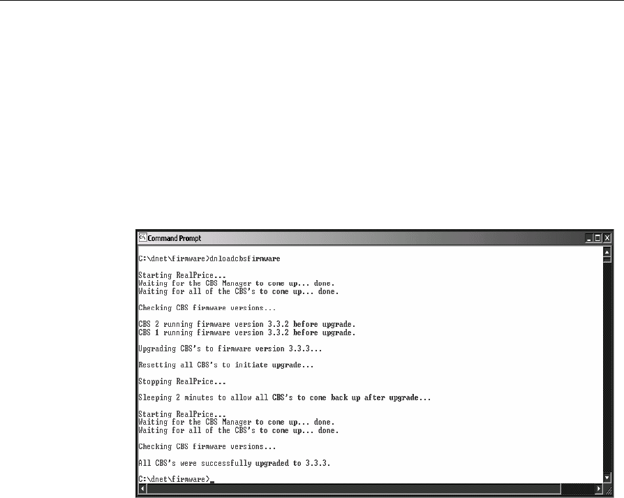
Chapter 3: Maintenance 3-19
The ImageFilename indicates that the firmware image is 3.3.4 and
ImageVersion reflects the same version.
TargetVersion is the firmware version that is targeted to be
upgraded. Wild card characters can be used.
3. Place the boot file and firmware image in the dnet\firmware
directory.
4. From a command prompt, type dnloadcbsfirmware. The
following screen displays if successful.
Note: dnloadcbsfirmware takes care of the stopping and starting
RealPrice as well as flashing firmware. The process will take a few
minutes. Please be patient while the entire process is carried out.
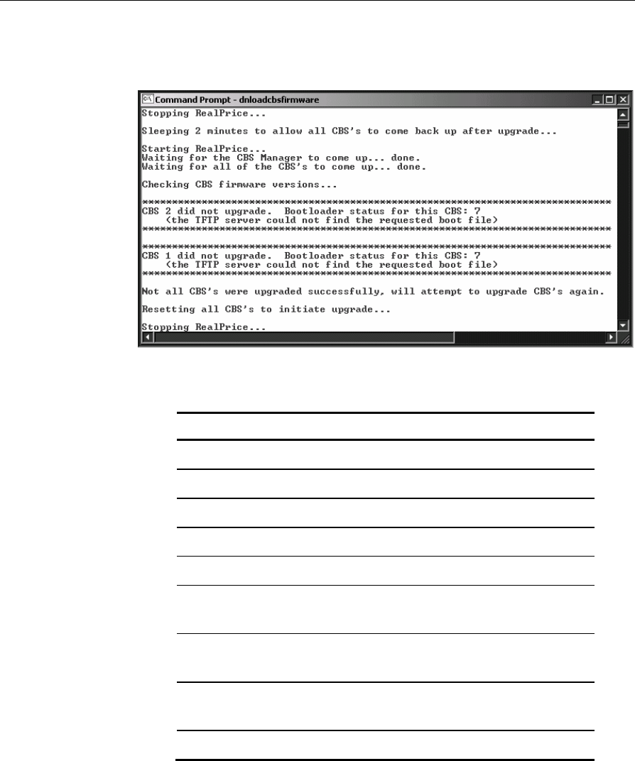
3-20 Chapter 3: Maintenance
5. If the firmware upgrade was unsuccessful, the following screen
displays.
The table below shows the possible errors while upgrading the CBS.
Error Code Description
0 Success
1 an unrecognized failure occurred
3 No DHCP server responded to boot request
4 The TFTP server address is unknown
5 the TFTP server did not reply to request
7 the TFTP server could not find the requested
boot file
8 critical information is missing from the boot
file
9 the TFTP server could not find the requested
image file
10 the new image file and boot file information

Chapter 3: Maintenance 3-21
do not match
11 the new image file sumcheck is bad
12 the new image is incompatible with the
hardware
13 an error occurred while writing to flash
memory
Note: dnloadcbsfirmware attempts to upgrade the CBSs three times. If
CBSs report failure to upgrade after all attempts, power cycle the target
CBS units. The user may manually power cycle the CBSs or initiate a
soft reboot.
Manual Power Cycle
To manually power cycle the units, unplug the CBS Power Supplies
from the AC source. Reconnect each power supply starting with the
power supply connected to the primary CBS. Continue
reconnecting each power supply.
Soft Reboot
To initiate a soft reboot, from a command prompt, type
dnCBSreset. It takes a few minutes to reset the CBSs and
complete the firmware update.
6. Optionally, examine the target CBS units to confirm that the
firmware update was successful.
Use the utilities dnCBSFirmware and dnCBSDiags to confirm the
success of the firmware update.
dnCBSFirmware
From a command line prompt, type dnCBSFirwmare to display
the ARM version (firmware version level) for each CBS in the
RealPrice system.
If the firmware update has been successful, the DOS window
displays all of the CBSs with the correct firmware level listed.
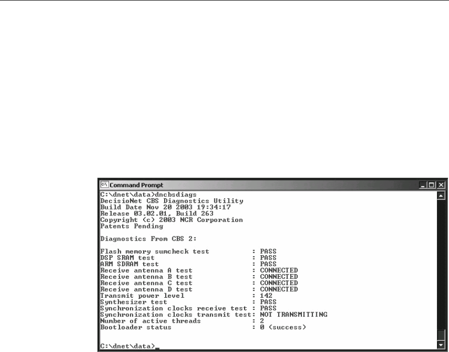
3-22 Chapter 3: Maintenance
If the result of dnCBSFirmware shows different versions among
the CBSs or no change to the firmware version, run dnCBSDiags to
determine the error.
dnCBSDiags
From a command line prompt, type dnCBSDiags to view the
diagnostics for each CBS.
Review the Bootloader Status entry which reports the status of the
Bootloader update process. 0 (success) indicates that the process
has been successful.
7. Troubleshoot problems with the firmware update.
Verify that the TFTP Server is installed and configured properly.
See section “NCR TFTP Configuration” later in this chapter.
Verify that the DHCP Server is configured properly.
Verify that the boot file is correctly formatted and defines the
correct file to use for the upgrade.
Note: The process may need to be repeated to successfully update the
firmware.
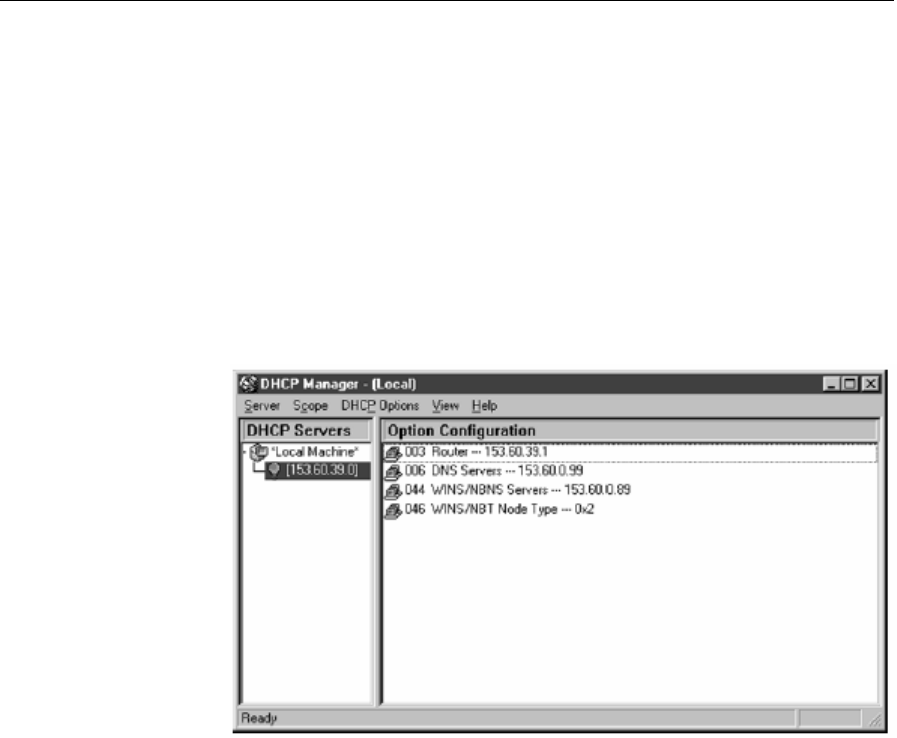
Chapter 3: Maintenance 3-23
DHCP Server Configuration
DHCP is optional and depends on how the RealPrice system is
configured in a store environment.
If the TFTP server is running on a different server than the RealPrice
server or if a different TFTP server is used, DHCP needs to be
configured.
To configure the Windows NT 4 Server DHCP server to work with the
NCR TFTP server, vendor specific information needs to be configured.
1. Open the DHCP Manager.
2. Select DHCP OptionsÆScope.
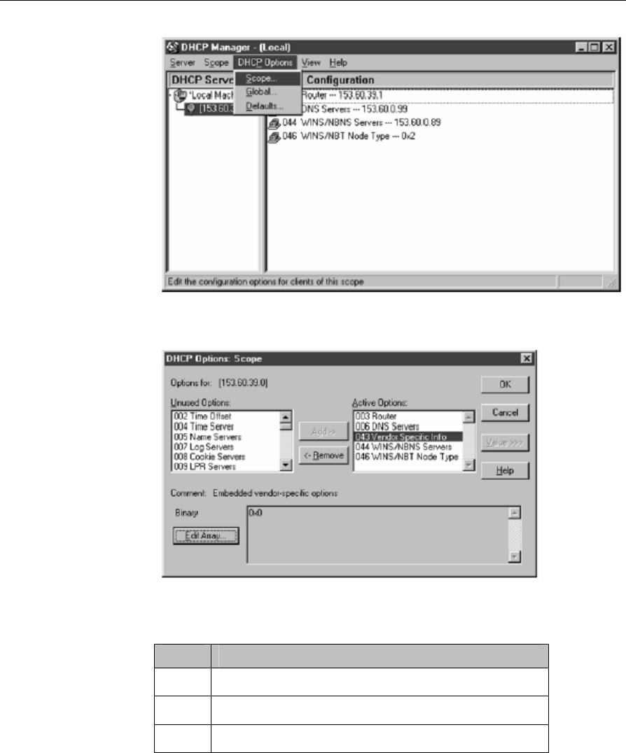
3-24 Chapter 3: Maintenance
3. Select 043 Vendor Specific Info and select Add to make it an active
option.
4. Select Edit Array button.
5. Enter the following values in the Numeric Value Array Editor:
Value Description
99 Required
5 Required
153 First Octet for IP address of TFTP server
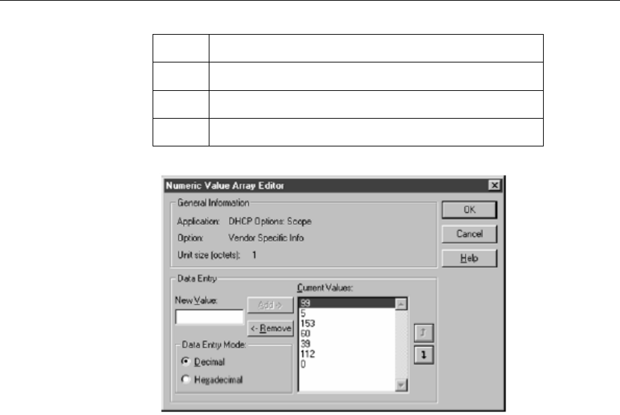
Chapter 3: Maintenance 3-25
60 Second Octet for IP address of TFTP server
39 Third Octet for IP address of TFTP server
205 Fourth Octet for IP address of TFTP server
0 Required
6. Select OK to save the values.
Updating Firmware Before RealPrice Base Software Installed
Under normal circumstances a user utilizes server components and
diagnostic features released with RealPrice Base software package;
however, a firmware update may be accomplished before the base
software is installed. The following limitations and restrictions apply:
A DHCP server must be configured to specify option 43 (Vendor
Specific Info) as described in the previous section.
A native TFTP server must be present. NCR TFTP Server ships and is
installed with the RealPrice Base software package.
No diagnostic capabilities are available to assist with troubleshooting.

3-26 Chapter 3: Maintenance
To use DHCP as a means of initiating a firmware update, the CBS
requires that a DHCP server specify a TFTP server name using option
43. The DHCP server must allow for specifying option 43 as an ASCII
string representing the TFTP server’s IP address in standard dotted
decimal notation. See DHCP Server Configuration above.
Using Static IP Addresses
If CBSs are configured to work without a DHCP server (static IP
addresses), each CBS uses the address of the RealPrice server as the
TFTP server address.
To use this alternate method, the CBS must already be aware of the
RealPrice server.
This can only be accomplished if the CBS first establishes a connection
with the RealPrice server during normal operation and stores its
address in non-volatile memory.
At boot time, the CBS immediately goes to the application image and
begins normal operation in the event that it cannot determine the TFTP
server address.
NCR TFTP Configuration
When the RealPrice Base software is installed, the NCR TFTP Server is
installed as a service configured to start automatically on reboot. If a
different TFTP server is installed and used, the NCR TFTP service
needs to be disabled.
The 7730 Firmware Management System (Firmware Bootloader) uses
NCRTFTPS to flash application image, the binary image that contains
the machine instructions for normal CBS operations.
The NCR TFTP Server can run as either a Windows NT service or an
application.
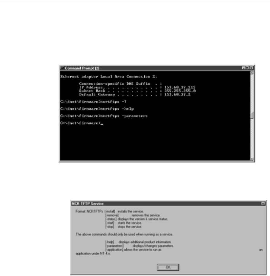
Chapter 3: Maintenance 3-27
Command Line Parameters
The NCR TFTP Server does not normally provide an interactive user
interface when running as a service. It is stopped and started like other
NT services, controlled through the Services dialog box in the Control
Panel. It may also be started from the command line.
The NCR TFTP Server supports the following command line
parameters (preceded by ‘-‘ or ‘/’):
• ? – displays command line parameter help
• help – displays additional product information
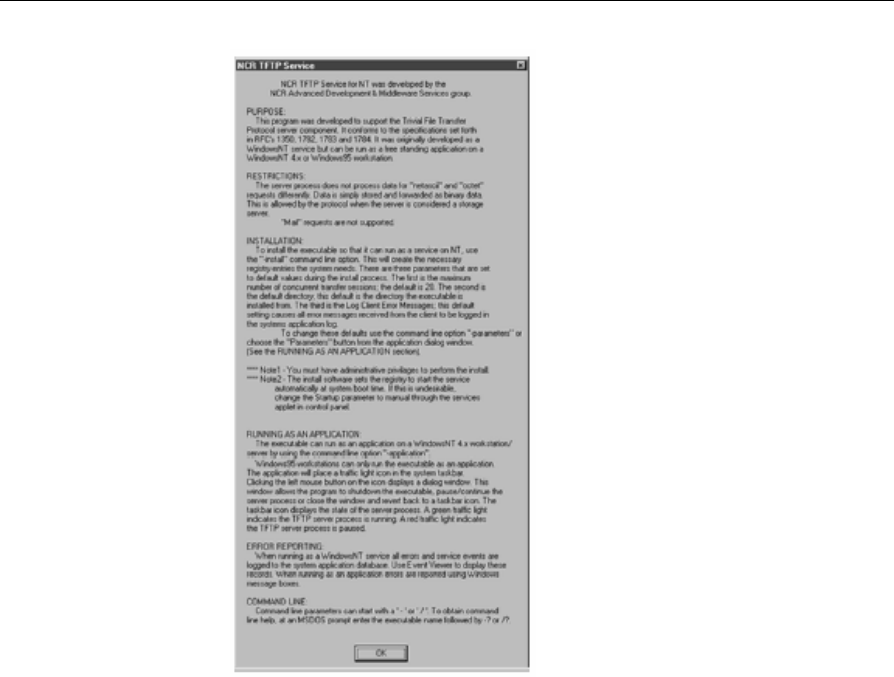
3-28 Chapter 3: Maintenance
• install – installs the service
• remove – removes the service
• status – displays version information and service status
• start – starts the service
• stop – stops the service
• parameters – displays/changes parameters
If NCR Fit Client is installed, RealPrice overwrites the NCR TFTP
server and increases the maximum number of sessions for TFTP server
from default 20 to 40.
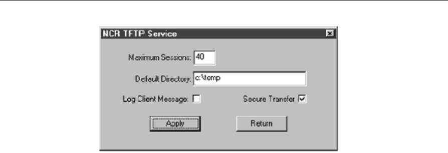
Chapter 3: Maintenance 3-29
No changes need be made to Default Directory unless running TFTP
server on a different server than RealPrice server.
• application – run executable as an application on Windows NT 4.x
workstation or server

Appendix A: Parts Order Information
CBS
Model Number
The CBS's twelve-digit model number is located on its name plate. The
model number contains important information used to ensure that a
replacement CBS matches the site's requirements. The twelve-digit
model number is defined in the following illustration.
7730 10 90 9011
Language Code
Major Model Code
Class Number
Sub Model Code
Power Code
18671
Major Model Code
Major Model Code Description
10 CBS III
20 CBS III release 3.4
Sub Model Code
The following sub model codes identify the CBS.
Sub Model Code Description/Version
11 CBS III, 1W, U.S. & Canada
12 CBS III, 500 mW, EMEA
13 CBS III, 500 mW, Netherlands (legacy model - not for

A-2 Appendix A: Parts Order Information
use in new sites, replaced by 1015)
14 CBS III, 100 mW, France
15 CBS III, 100 mW, Denmark, Italy, Netherlands,
Norway
16 CBS III, 1W, Australia
Language Code
The following is the language code.
Language Code Description
90 No language characteristics
Power Code
The following is the power code.
Power Code Description
90 The CBS does not have an internal power supply.
It receives power from the CBS power supply.
Kit Numbers
The following kits support RealPrice System installations.
Category Kit Number Description
Antenna 7730-K050-V003 Receive antenna kit, plenum rated
7730-K053-V001 Kit-Transmit antenna w/cable
7730-K054-V003 Kit-Receive antenna w/15 m cable (for
100 mW CBS)
7730-K055-V002 Kit-Receive antenna (6m lead) and
12m cable
7730-K056-V001 Kit-Receive antenna (6m lead) and 9m

Appendix A: Parts Order Information A-3
cable
7730-K057-V001 Freezer Mounting Bracket
ESL 7730-K100-V006 Kit-ESL, Single Facing 2x5
7730-K110-V006 Kit-ESL, Single Facing, 3+2, Black
7730-K200-V006 Kit-ESL, Small 2x5
7730-K210-V006 Kit-ESL, Small 2x5, w/icon
7730-K230-V006 Kit-ESL, Small 2x5, UK
7730-K270-V006 Kit-ESL, Small, 4+5
7730-K300-V006 Kit-ESL, Standard, 4+8
7730-K301-V006 Kit-ESL, Standard, 4+8, Freezer
7730-K310-V006 Kit-ESL, Standard, 1x8
7730-K311-V006 Kit-ESL, Standard, 1x8, Freezer
7730-K320-V006 Kit-ESL, Standard, 3x6, w/ icon
7730-K321-V006 Kit-ESL, Standard, 3x6, w/ icon,
Freezer
7730-K330-V006 Kit-ESL, Standard, 4+8, UK
7730-K331-V006 Kit-ESL, Standard, 4+8 UK, Freezer
7730-K340-V006 Kit-ESL, Standard, 5+5
7730-K341-V006 Kit-ESL, Standard, 5+5, Freezer
7730-K350-V006 Kit-ESL, Standard, 3x
7730-K351-V006 Kit-ESL, Standard, 3x, Freezer
7730-K360-V006 Kit-ESL, Standard, 1x8, w/icon
7730-K361-V006 Kit-ESL, Standard, 1x8, w/icon,
Freezer

A-4 Appendix A: Parts Order Information
7730-K370-V006 Kit-ESL, Standard, 4+5
7730-K371-V006 Kit-ESL, Standard, 4+5, Freezer
7730-K400-V006 Kit-ESL, Small Signage, 1x6
7730-K410-V006 Kit-ESL, Small Signage, 1x6, Rail
Mount
7730-K490-V001 Kit-Slider, Small Signage, Transparent
7730-K491-V001 Kit-Slider, Small Signage, Transparent,
Without Divider
7730-K500-V006 Kit-ESL, Large Signage, 2x6
7730-K510-V006 Kit-ESL, Large Signage, 2x6, Rail
Mount
7730-K590-V001 Kit-Slider, Large Signage, Transparent
Clips 7730-K890-V001 C-channel clips, 0 degree
7730-K891-V001 C-channel clips, 25 degree
7730-K892-V001 C-channel clips, 40 degree
7730-K893-V001 ESL Spring Clip, 15 degree
Power
Supply
7730-K0113-
V001
CBS II central power supply kit 7730
release 3.4 48V power supply, US
version
7730-K0124-
V001
7730 central power supply kit, int’l
bare wire plug 7730 release 3.4 48V
power supply, International version
7730-K013-V001 7730 release 3.4 48V power supply, US
version
7730-K014-V001 7730 release 3.4 48V power supply,
International version

Appendix A: Parts Order Information A-5
RBA
Modules
7730-K070-V001 Kit of five (5) US (-1.5 dBm) RBA
modules
7730-K071-V001 Kit of five (5) EU (10 dBm) RBA
modules
7730-K090-V001 NCR 7730 DecisioNet Overlay
Application Services – 10 pieces

A-6 Appendix A: Parts Order Information
10/100 Unmanaged Switches
The following auto-sensing unmanaged switches may be used as
Ethernet 100Base-T compatible hubs in RealPrice Systems.
Supplier Part
Number NCR Class Number
NCR Part Number
Description
AT-FS708-10 7533-0003-0000
877-0152823
8-port 10/100 with internal power
supply and U.S. power cord
AT-FS708E-10 7533-0001-0000
877-2270037
8-port 10/100 with external power
supply and U.S. power cord
Cable Numbers
The following cables support RealPrice System installations.
Category Cable Number Part Number Description
CBS 1416-C465-0018 230-0146539 Cable-TX Antenna, 1.8m,
TNC to RP SMA, plenum
rated (discontinued)
1424-C057-0180 230-0134951 Cable-RX Antenna, 18m,
BNC to BNC, plenum
rated
1416-C520-0150 230-0134953 Cable-RX Antenna, 15m,
BNC to BNC, plenum
rated (100 mW CBS)
Power
Supply
1416-C463-9999 497-0413234 Cable – Central power
supply pigtail

Appendix A: Parts Order Information A-7
Part Numbers
The following list identifies RealPrice component part numbers used
when ordering replacement parts.
Part Name Part Number
CBS III, 1W, U.S. & Canada 497-0428071
CBS III, 500 mW, EMEA 497-0428072
CBS III, 500 mW, Netherlands 497-0428073
CBS III, 100 mW, France 497-0428074
CBS III, 100 mW, Denmark, Italy, Norway,
Netherlands
497-0428075
CBS III, 1W, Australia 497-0428076
Kit, Receive antenna w/18m cable 497-0421212
Kit, Receive antenna w/15 m cable (for 100 mW
CBS)
497-0422223
Kit-Transmit antenna w/cable (discontinued) 497-0422220
CBS II central power supply kit 497-0421230
7730 central power supply kit, int’l bare wire plug 497-0421229
Antenna mounting hardware 497-0414027
Cable-TX Antenna, 1.8m, TNC to RP SMA,
plenum rated
230-0146539
Cable-RX Antenna, 18m, BNC to BNC, plenum
rated
230-0134951
Cable-RX Antenna, 15m, BNC to BNC, plenum
rated (100 mW CBS)
230-0134953
Cable – Central power supply pigtail 497-0413234

G
Glossary
A
Antenna
A device used to transmit and receive RF communication between
a CBS and ESLs. One transmit and up to four receive antennas may
be attached to each CBS. Antennas are usually installed on the
ceiling.
ARP (Address Resolution Protocol)
A network communication protocol used to provide a cross
reference between MAC addresses and IP addresses.
Attachments
Mounting devices used to attach ESLs to shelf rails.
B
Base Runtime Software
A software application for the RealPrice System that runs on the
RealPrice Software Controller and is not dependent on the type of
POS system used. The Base Runtime Software controls the core
RealPrice functionality such as initialization of a ESL, display of
price on an ESL, and diagnostics.
C
CBS (Communication Base Station)
CBSs receive and transmit data and control functions to the ESLs.
Up to 40 CBSs can be installed in a store. One CBS is defined as the
primary CBS and the others as secondary CBSs. CBSs are usually
installed in the ceiling.

A-2 Glossary
CBS Power Supply
This external AC/DC converter supplies DC power to a maximum
of three CBSs. An additional CBS Power Supply is required for
each additional group of three CBSs.
Country Code Keys
CBS parameters that identify the power level, number of frequency
bands, and the operating frequencies specific to each CBS model.
Coverage Area
An area within a store where there is reliable RF communication
between CBSs and ESLs. More than one CBS is required in a large
store to attain adequate transmission reliability.
E
ESL (Electronic Shelf Label)
An ESL is the device attached to the store shelf that displays
information for the customer.
I
Install Mode
A CBS operating mode where all CBS's communicate with ESLs
using the odd numbered timeslots (1-23). This mode is used when
running installation and test utilities; Initial Load, RF Certification,
and dncalib, and is not intended for normal day-to-day operations.
IP (Internet Protocol)
IP Address
An address format (xxx.xxx.xxx.x) used to communicate with
devices or components in a network. The format includes network
IDs, subnetwork IDs, and host IDs.
ISP (In-Store Processor)
The computer in the store that contains the price database used by
the POS system. The ISP integrates PLU information into the
RealPrice System.

Glossary A-3
M
MAC (Medium Access Control)
A communications protocol. The MAC protocol is used to provide
the data link layer of an Ethernet LAN system.
N
Normal Mode
A CBS operating mode where each CBS communicates with its
assigned ESLs using 2 of the 24 available timeslots, such as 1-13, 2-
14, 3-15, and so forth. This mode is used for normal day-to-day store
operations to provide the minimum amount of communication air
time resulting in the most efficient environment for co-existence
with other RF devices in the store.
R
RealPrice Database
A MySQL database used to store information relative to all ESL
management.
RealPrice Software Controller
This refers to the In-Store Processor (ISP) or a Dedicated PC (DPC).
This is the computer physically connected to the primary CBS that
sends price information from the PLU file to the RealPrice System
for display on ESLs.
RealPrice Standalone System
A system that runs the RealPrice Software on a dedicated PC
separate from the ISP. In this situation the DPC has a copy of the
store data base and communicates with the ISP to receive
maintenance (price update) data.
RF (Radio Frequency)
S
Store ID
A unique number is assigned to each store and used by the
RealPrice System to prevent unintentional transmission of signals
between stores.

A-4 Glossary
T
Time Slot
A unit of time assigned to each ESL during which a CBS transmits
either a downlink message to an ESL, or receives
acknowledgements (ACKs) back from an ESL. Each CBS is assigned
2 time slots.
U
Uplink
An uplink is an acknowledgment message (ACK) sent from an ESL
to a CBS in response to a downlink burst.

Index
—1—
10/100 Unmanaged Switches, A-6
—A—
Alternate CBS Mounting Solution, 2-22
Antennas
Installing, 2-27, 2-28
Overview, 2-27
Replacing, 3-6
—B—
Battery replacement, 3-9
—C—
Cable Numbers, A-6
Cables
Cable usage table, 2-13, 2-14
Recommended cables, 2-14
CBS
Adding, 3-5
Cable usage table, 2-13, 2-14
Connecting Ethernet data cables, 2-22
Data connectors, 2-17
Installing, 2-7, 2-20
Kit numbers, A-2
LEDs, 2-18
Model number and codes, A-1
Parts order information, A-1
Power connectors, 2-18
Power supply replacement, 3-7
Recommended cables, 2-14
Replacing, 3-4
System cable connections, 2-7, 2-9
CBS Hardware Configuration, 2-38
CBS Hopping Table, 2-12
CBS Numbering, 2-8
CBS Timeslots, 2-11
Chapter summaries, 1-2
Connecting Ethernet Data Cables, 2-22
Connecting Secondary CBSs, 2-24
Connecting the Ethernet Hub to the
Primary CBS, 2-23
—E—
ESL
Battery replacement, 3-9
—H—
Hanging an Antenna from a Roof Truss,
2-36
Hardware installation, 2-1
hopping frequencies, 2-12
—I—
Installation
Antennas, 2-27
CBS, 2-7
CBS power supply, 2-25
CBS power supply to primary CBS, 2-
24
Hardware, 2-1
Recommendations, 2-2
—K—
Kit numbers, A-2
—M—
Maintenance, 3-1
Mounting an Antenna in a Freezer, 2-31
Mounting an Antenna to a Suspended
Ceiling, 2-29
—P—
Part Numbers, A-7
—R—
RealPrice for AIX CBS Setup Utility, 3-3
RealPrice Support Utility, 3-3
Reference materials, 1-3
Release 3.0 and Release 3.1 Information,
1-1
Removing a CBS from the mounting
bracket, 2-22
Replacing hardware components, 3-1
Windows 2000/NTand AIX
Environment Procedures, 3-2
—S—
Sample Store Cabling, 2-10
Site certification tools, 1-4
—T—
Timeslots, 2-11
Tools and supplies, 2-6
—U—
Updating a CBS's Firmware Images, 3-11
Updating CBS's Firmware Image –
Firmware Bootloader, 3-15
Updating CBS's Firmware Image (ftpdl),
3-11
—V—
Verifying Communication Links, 2-38

B005-0000-1491 Sept 2004