NCR 7156 User Manual To The F3ad1f65 977c 4330 Ade1 145324b112a3
User Manual: NCR 7156 to the manual
Open the PDF directly: View PDF ![]() .
.
Page Count: 38
- Contents
- Chapter 1: The 7156 Printer
- Chapter 2: Setting Up and Using the Printer
- Chapter 3: Ordering Paper and Supplies

NCR 7156 Thermal Receipt and
Impact Slip Printer:
Setup and User’s Guide
BD20-1435-A
Issue B
September 1998

September 1998ii
Disclaimer
Information in this document is subject to change without notice. Therefore, before using
this document, consult your NCR sales representative for information that is applicable and
current. NCR reserves the right to improve products as new technology, components,
software, and firmware become available.
No part of this document may be reproduced or transmitted in any form or by any means,
electronic or mechanical, for any purpose without the express written permission of NCR.
Copyright
Copyright © 1997, 1998 by NCR Corporation
Dayton, Ohio USA
All rights reserved
Printed in USA
Confidential, Unpublished
Property of NCR Corporation
Trademarks
NCR is the registered trademark of NCR Corporation. Other trademarks and registered
trademarks are the property of their respective holders.

September 1998 iii
Important Information to the User
In order to ensure compliance with the Product Safety, FCC and CE marking requirements,
you must use the power supply, power cord, and interface cable which were shipped with
this product or which meet the following parameters:
Power Supply
UL Listed (QQGQ), Class 2 power supply with SELV (Secondary Extra Low Voltage), non-
energy hazard output, limited energy source, input rated 100-240 Vac, 1.5/0.8 A, 50/60 Hz,
output rated 24 Vdc, 2.3 A.
Use of this product with a power supply other than the NCR power supply will require
you to test this power supply and NCR printer for FCC and CE mark certification.
Interface Cable
A shielded (360 degree) interface cable must be used with this product. The shield must be
connected to the frame or earth ground connection or earth ground reference at EACH end
of the cable.
Use of a cable other than described here will require that you test this cable with the NCR
printer and your system for FCC and CE mark certification.
Power Cord
A UL listed, detachable power cord must be used for this product. For applications where
the power supply module may be mounted on the floor, a power cord with Type SJT
marking must be used. For applications outside the US, power cords which meet the
particular country’s certification and application requirements should be used.
Use of a power cord other than described here may result in a violation of safety
certifications which are in force in the country of use.

September 1998iv
Federal Communications Commission (FCC)
Radio Frequency Interference Statement
Warning: Changes or modifications to this unit not expressly approved by the party
responsible for compliance could void the user’s authority to operate the equipment.
Note: This equipment has been tested and found to comply with the limits for a Class A
digital device, pursuant to Part 15 of the FCC Rules. These limits are designed to provide
reasonable protection against harmful interference when the equipment is operated in a
commercial environment. This equipment generates, uses, and can radiate radio frequency
energy and, if not installed and used in accordance with the instruction manual, may cause
harmful interference to radio communications. Operation of this equipment in a residential
area is likely to cause harmful interference in which case the user will be required to correct
the interference at his own expense.
Communication Cables
Shielded communication cables must be used with this unit to ensure compliance with the
Class A FCC limits.
Information to User
This equipment must be installed and used in strict accordance with the manufacturer's
instructions. However, there is no guarantee that interference to radio communications will
not occur in a particular commercial installation. If this equipment does cause interference,
which can be determined by turning the equipment off and on, the user is encouraged to
contact NCR immediately.
The NCR company is not responsible for any radio or television interference caused by
unauthorized modification of this equipment or the substitution or attachment of
connecting cables and equipment other than those specified by NCR. The correction of
interferences caused by such unauthorized modification, substitution or attachment will be
the responsibility of the user.
Industry Canada (IC)
Radio Frequency Interference Statement
This Class A digital apparatus meets all requirements of the Canadian Interference-Causing
Equipment Regulations.
Cet appareil numérique de la classe A respecte toutes les exigences du Règlement sur le matériel
brouilleur du Canada.
7156 Setup and User’s Guide Contents
September 1998 v
Contents
Chapter 1: The 7156 Printer 1
Features and Options..................................................................................................2
Receipt Station......................................................................................................2
Slip Station............................................................................................................3
Both Stations.........................................................................................................3
General Features...................................................................................................3
Options..................................................................................................................4
Chapter 2: Setting Up and Using the Printer 5
What Is in the Box?......................................................................................................5
Removing the Packing Material.........................................................................6
Repacking the Printer..........................................................................................8
Choosing a Location....................................................................................................9
Connecting the Cables..............................................................................................10
Turning On the Printer.............................................................................................12
Loading and Changing the Receipt Paper.............................................................13
Removing the Paper Roll...................................................................................14
Putting In the Paper Roll...................................................................................15
Putting In and Changing the Ribbon Cassette ......................................................16
Removing the Ribbon Cassette.........................................................................16
Putting In the Ribbon Cassette.........................................................................17
Printing on Forms or Checks...................................................................................18
Validating and Verifying Checks............................................................................20
Testing the Printer.....................................................................................................22
Running the Print Test by Power Cycling the Printer...................................22
Running the Print Test by Opening and Closing the Cover.........................22
Sample Print Test...............................................................................................23
Setting Switches.........................................................................................................24
Cleaning the Printer..................................................................................................26

Contents 7156 Setup and User’s Guide
September 1998vi
Chapter 3: Ordering Paper and Supplies 27
Ordering Thermal Receipt Paper ............................................................................27
Ordering Forms.........................................................................................................28
Ordering Ribbon Cassettes.......................................................................................28
Ordering Other Supplies..........................................................................................29
Ordering Documentation.........................................................................................29
Revision Record
Issue Date Remarks
A September 97 First printing
B September 98 Second printing, including
minor revisions
7156 Setup and User’s Guide Chapter 1: The 7156 Printer
September 1998 1
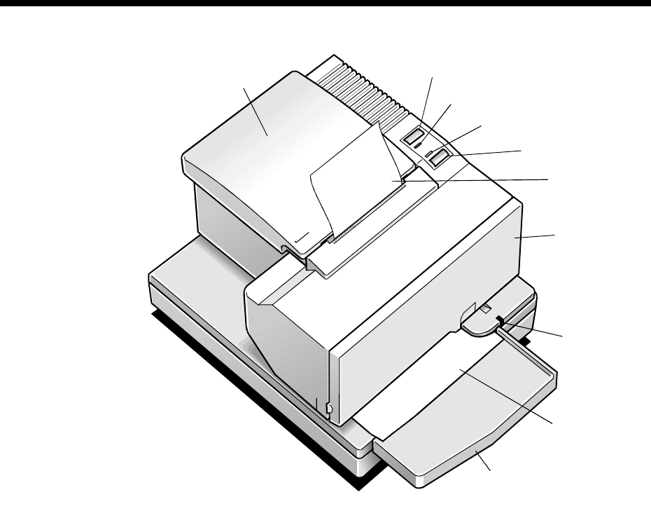
Chapter 1: The 7156 Printer
Receipt
Cover
Receipt
Paper Feed
Button
Front
Cover
LED
Extended
Slip Table
Slip or
Check
On Line Button
Paper Status
Red Led
On Line
Green LED
The 7156 printer is a fast, quiet, and very reliable multiple function printer.
Relatively small, it is easy to setup and use. It prints receipts, validates and prints
checks, and prints on a variety of single- or multiple-part forms. There is no
journal as it is kept electronically by the host computer.
Chapter 1: The 7156 Printer 7156 Setup and User’s Guide
September 19982
The industry-standard RS-232C communication interface allows the 7156 to be
connected to any host computer that uses RS-232C. Control codes are provided for
easy migration of applications written for Epson as well as other NCR printers.
With thermal printing technology on the more frequently used receipt station,
there is no ribbon cassette to change and paper loading is extremely simple.
Printing on single- or multiple-part forms, validating checks, and printing checks
is also easy in the accommodating slip station. An additional option is the
Magnetic Ink Character Recognition (MICR) check reader with parsing which
reads account numbers on checks for easy verification. An extended slip table is
available for handling large forms and is standard with the MICR check reader
option.
Features and Options
The 7156 printer comes with several features and options.
Receipt Station
Thermal printing
Standard pitch (host selectable): 15.2 characters per inch, 44 columns
Compressed pitch (host selectable): 19.0 characters per inch, 56 columns
Resident bar codes
Code 39
Code 128
UPC-A
UPC-E
JAN8 (EAN)
JAN13 (EAN)
Interleaved 2 of 5
Codabar
Drop-in paper loading requiring no spindle or threading paper
Paper low indicator
Paper exhaust
7156 Setup and User’s Guide Chapter 1: The 7156 Printer
September 1998 3
Slip Station
Bi-directional, impact printing
Standard pitch (host selectable): 13.9 characters per inch, 66 columns
Compressed pitch (host selectable): 17.1 characters per inch, 80 columns
Printing of forms up to five plies
Front insertion of forms with forms stop
Side insertion of forms with override of forms stop
Automatic and manual insertion of forms
Form alignment sensors and Slip In LED indicator
Horizontal flat-bed slip table with optional extension (standard with MICR
check reader)
Snap-on ribbon cassette
Both Stations
Variety of print modes: double high (receipt station only), double strike (slip
station only), double wide, upside down, and rotated
Two resident character sets:
PC Code Page 437 (US)
PC Code Page 850 (Multilingual)
16K RAM for downloaded character sets or bit-mapped graphics
(such as logos)
General Features
Cover open sensors
Industry standard RS-232C communication interface
History EEROM for custom settings
Power and communication support for a remote 2x20 pass-through display
Audible tone (controlled by application)
Note: The 7156 does not use a paper journal. The journal is kept electronically by
the host computer.
Chapter 1: The 7156 Printer 7156 Setup and User’s Guide
September 19984
Options
Magnetic Ink Character Recognition (MICR) check reader built into the slip
station for verifying checks (includes custom MICR field parsing)
Extended slip table for handling large forms (standard with MICR
check reader)
Paper cutter (receipt station)
Remote power supply
Two cash drawer drivers
Communication cable

7156 Setup and User’s Guide Chapter 2: Setting Up and Using the Printer
September 1998 5
Chapter 2: Setting Up and Using the Printer
What Is in the Box?
The following items are packed in the shipping box (printers shipped in bulk may
not include all of these items):
Printer enclosed in a plastic bag and foam pack
Thermal receipt paper roll (inside receipt bucket)
Test printout protecting the thermal printhead (inside receipt bucket)
Cardboard support for cantilever (on slip table)
Foam restraint for carriage (behind front cover)
Power supply with cable connecting to printer and power supply cord
connecting to power outlet (only if ordered with the printer)
Ribbon cassette
Clips for securing cables under the base
If not in the box, the clips will be attached or molded to the base.
Installation report card (please complete this form and return to NCR)
7156 Thermal Receipt and Impact Slip Printer: Setup and User’s Guide
(this booklet)
These items may be ordered as options from NCR and will be shipped separately:
Communication cable (from host computer to printer)
Cash drawer with cables (may be ordered from other equipment suppliers: see
“Ordering Other Supplies” in chapter 3)
Chapter 2: Setting Up and Using the Printer 7156 Setup and User’s Guide
September 19986
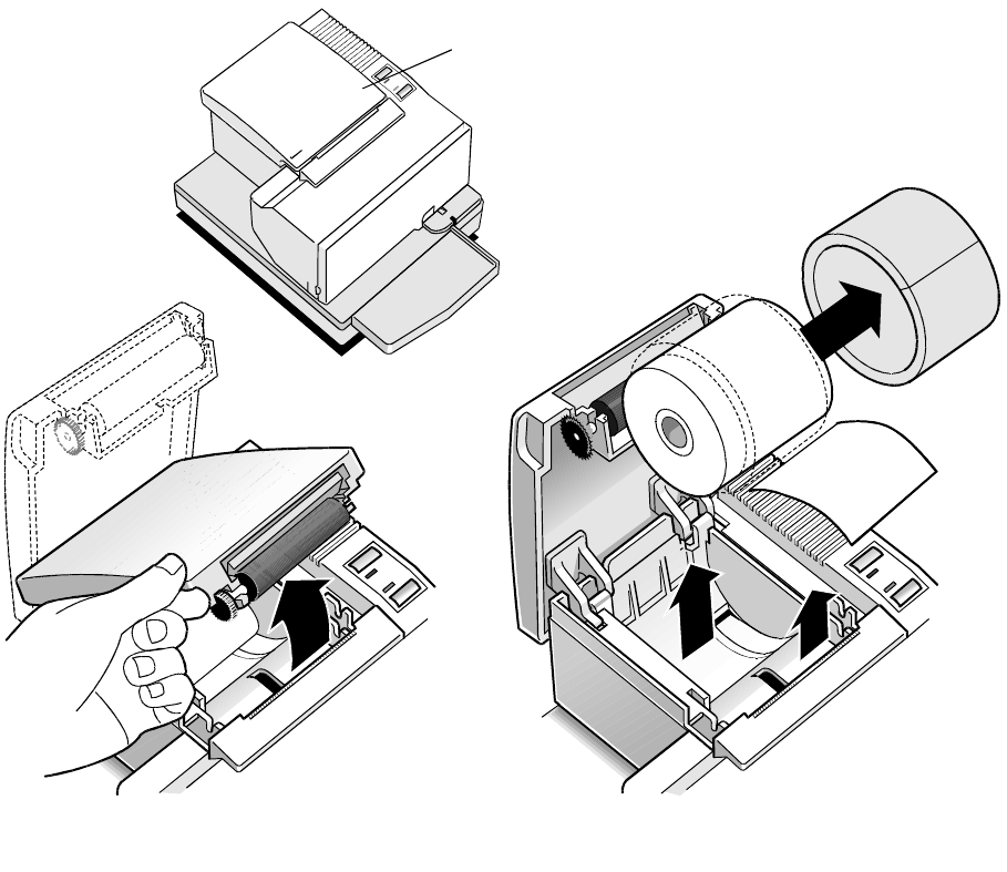
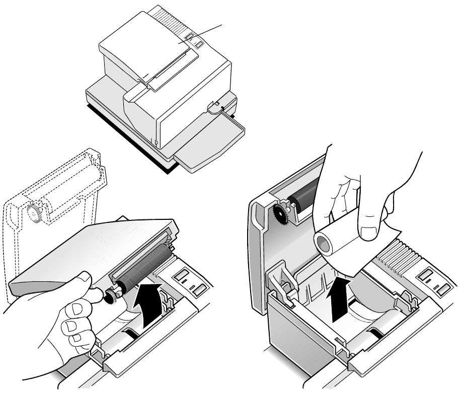
Removing the Packing Material
1. Once the printer is removed from the foam pack and plastic bag, open the
receipt cover by pulling up on the front left corner.
2. Remove the paper roll, discard any packing material, and remove the test
printout from inside the receipt bucket.
Receipt
Cover
12
7156 Setup and User’s Guide Chapter 2: Setting Up and Using the Printer
September 1998 7
3. Open the front cover and remove the foam restraint.
4. Remove the cardboard support from the slip table.
5. Remove the ribbon cassette and cables from the box.
6. Save all packing materials for future storing, moving, or shipping the printer.
7. Complete the Installation report card and send it to NCR.
Caution: Remove the foam restraint and the cardboard support before operating
the printer.
Front
Cover
3
4
Chapter 2: Setting Up and Using the Printer 7156 Setup and User’s Guide
September 19988
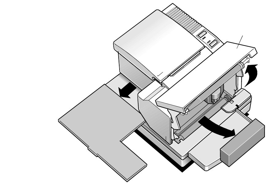
Repacking the Printer
Review the illustrations on the previous two pages to pack the printer.
1. Place receipt paper between the receipt cover and the printhead for protection.
2. Remove the ribbon cassette, move the carriage to the right, and place the foam
restraint between the left side of the printer and the carriage to protect the
carriage.
3. Place the cardboard support on the slip table.
4. Place the printer in the plastic bag and foam pack, place the packed printer in
the box and secure the box with packing tape.
5. If you are sending the printer to NCR for repair, call your NCR-authorized
service representative for instructions on where to send the printer.
Be prepared to answer questions concerning shipping and billing.
7156 Setup and User’s Guide Chapter 2: Setting Up and Using the Printer
September 1998 9
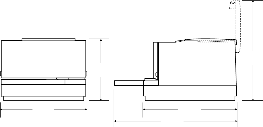
Choosing a Location
The 7156 printer takes up relatively little counter space and may be set on or near
the host computer. Make sure there is enough room to open the receipt cover to
change the paper and to open the front cover to change the ribbon cassette. The
illustration shows the actual dimensions of the printer, but leave several inches
around the printer for connecting and accessing the cables.
Note: The optional Magnetic Ink Character Recognition (MICR) check reader
feature has been factory adjusted for a normal operating environment with a host
computer. However, additional devices, such as CRT monitors, or large metal
surfaces that are near the printer can affect the printer’s magnetic field, causing
intermittent reading errors when the MICR check reader is in operation.
This condition can be easily diagnosed by checking the MICR check reader and
adjusting it if the factory setting has been altered by your operating environment.
See the Owner’s Guide for more information.
229 mm
(9.00 in.) 264 mm
(10.40 in.)
347 mm
(13.70 in.)
178 mm
(7.00 in.)
280 mm
(11.00 in.)
Chapter 2: Setting Up and Using the Printer 7156 Setup and User’s Guide
September 199810
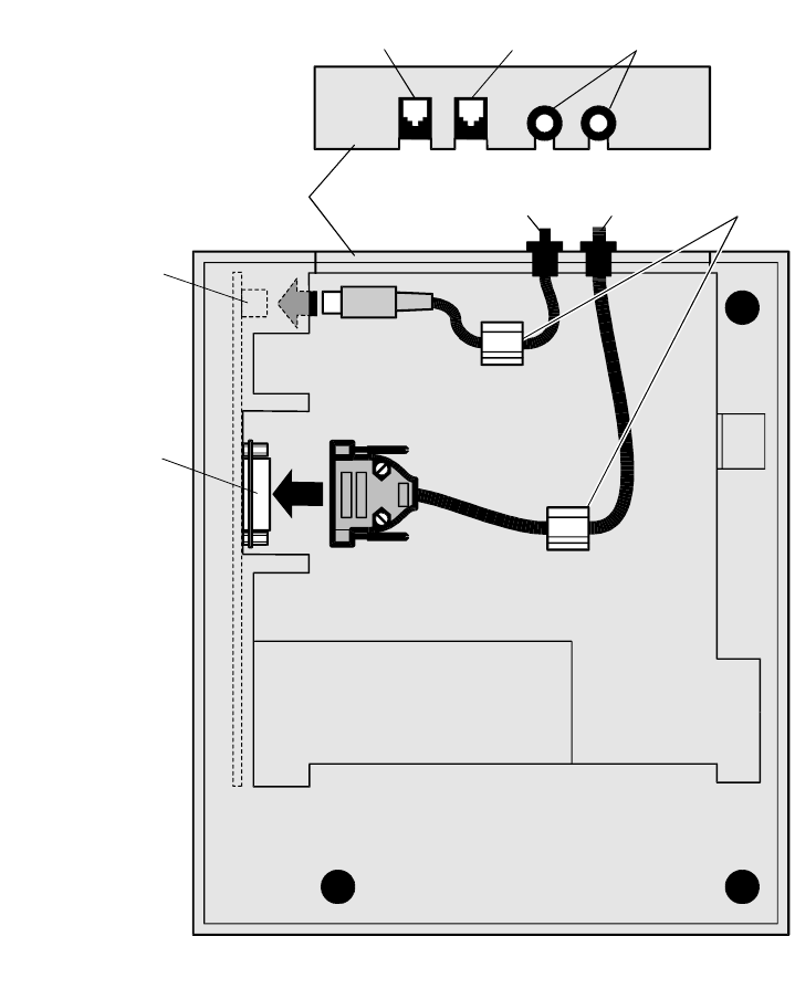
Connecting the Cables
There are three different types of cables that connect to the printer:
Power supply cable supplying power from the power supply
Communication cable connecting the printer to the host computer
Cash drawer cables connecting the printer to one or two cash drawers
Caution: Disconnect the power before connecting the cables. Always connect the
communication cable and cash drawer cables before connecting power to the
power supply. Always disconnect power to the power supply before disonnecting
the communication and cash drawer cables.
Follow these steps to connect the cables. See the illustration on the facing page.
1. Unplug the power supply from its power source.
2. Connect the power and communication cables to their respective connectors
under the printer as shown in the illustration.
Be sure to screw the communication cable to the connector on the printer.
3. Route the cables through the cable clamps on the bottom of the printer, then
through the two slots in the cable access cover as shown in the illustration.
Note: The strain relief bushings are shipped in the box and help secure the
cables. The cable clamps may be shipped in the box or may be attached or
molded to the bottom of the printer. Use the cable clamps or strain relief
bushings, or both, to keep the cables from being unplugged which may
damage the connectors or interrupt a transaction.
4. Connect the communication cable to the appropriate host computer connector.
5. Connect the cash drawer cables to the printer and cash drawers.
The connectors are standard phone jacks located at the rear of the printer.
6. Plug the power cord into the power supply, then plug the power supply into
an outlet.
At this point, the printer receives power. If the On Line LED (green) is on, the
printer is on-line. Otherwise, the printer is off-line.
7156 Setup and User’s Guide Chapter 2: Setting Up and Using the Printer
September 1998 11
Cable
Access
Cover
Communication
Connector
Bottom of the Printer
Power
Cable Communication
Cable
Power
Connector
Cash Drawer
Connector 1 Cash Drawer
Connector 2 Strain Relief
Bushings
Cable
Clamps

Chapter 2: Setting Up and Using the Printer 7156 Setup and User’s Guide
September 199812
Turning On the Printer
Paper Status
Red LED
On Line
Green LED
Paper Feed Button
On Line Button
with Recessed
Plunger
On Line Button
Paper Status
Red LED
On Line
Green LED
Paper Feed Button
Standard
Operator Panel Alternate Version
Operator Panel
Note: The operator panel may differ from the standard version (left) depending
on the model. On models matching the alternate version (right), use a paper clip or
pointed object to press the plunger to put the printer on- or off-line.
1. Press the On Line button (or plunger) to put the printer on-line, if it’s not
already on-line.
The printer goes through a self-test routine to ensure everything is working
properly then “beeps.” The On Line light (green) comes on indicating the
printer is on-line. When the printer has completed its “startup” cycle, it is
ready to receive data.
If the On Line light does not come on, the Paper Out light or the LED on the
slip table flashes, or the host computer indicates that there is a problem, see the
7156 Owner's Guide for more information.
2. Press the On Line button (or plunger) again to put the printer off-line.
Note: The printer receives power when the power supply is on even if the printer
is off-line. To completely remove power, press the On Line button (or plunger) to
put the printer off-line (On Line light is off), then unplug the power supply from
the outlet.
7156 Setup and User’s Guide Chapter 2: Setting Up and Using the Printer
September 1998 13
Loading and Changing the Receipt Paper
Although the illustrations show a used roll being removed, the instructions apply
to loading paper for the first time.
Change the paper when either of the following two conditions occurs:
Paper Status LED (red) flashes: the paper is low
There are approximately 1 ½ to 7 ½ meters (5-25 feet) of paper remaining on
the roll. Change the paper as soon as possible to avoid running out part way
through a transaction.
Depending on the application program, the host computer may alert you when
the paper is low.
Paper Status LED (red) turns on: the paper is out
Change the paper immediately or data may be lost.
Caution: Do not operate the printer or host computer if the printer runs out of
paper. The printer will not operate without paper, but it may continue to accept
data from the host computer. Because the printer cannot print any transactions, the
data may be lost.
Chapter 2: Setting Up and Using the Printer 7156 Setup and User’s Guide
September 199814
Removing the Paper Roll
1. Open the receipt cover.
2. Remove the used roll.
Receipt
Cover
2
1
7156 Setup and User’s Guide Chapter 2: Setting Up and Using the Printer
September 1998 15
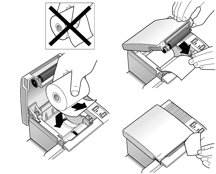
Putting In the Paper Roll
Note: Tear off the end of the new roll so that the edge is loose.
1. Place the new roll in the bin with a little extra paper extending over the front.
Be sure the paper unrolls from the bottom of the roll. Otherwise the paper will
not be printed on because the thermal coating will be on the wrong side.
2. Close the receipt cover.
3. Remove the excess paper by tearing it against the tear-off blade.
In addition to the tear off-blade, some printers use a knife to cut the receipt.
2
1
3
Chapter 2: Setting Up and Using the Printer 7156 Setup and User’s Guide
September 199816
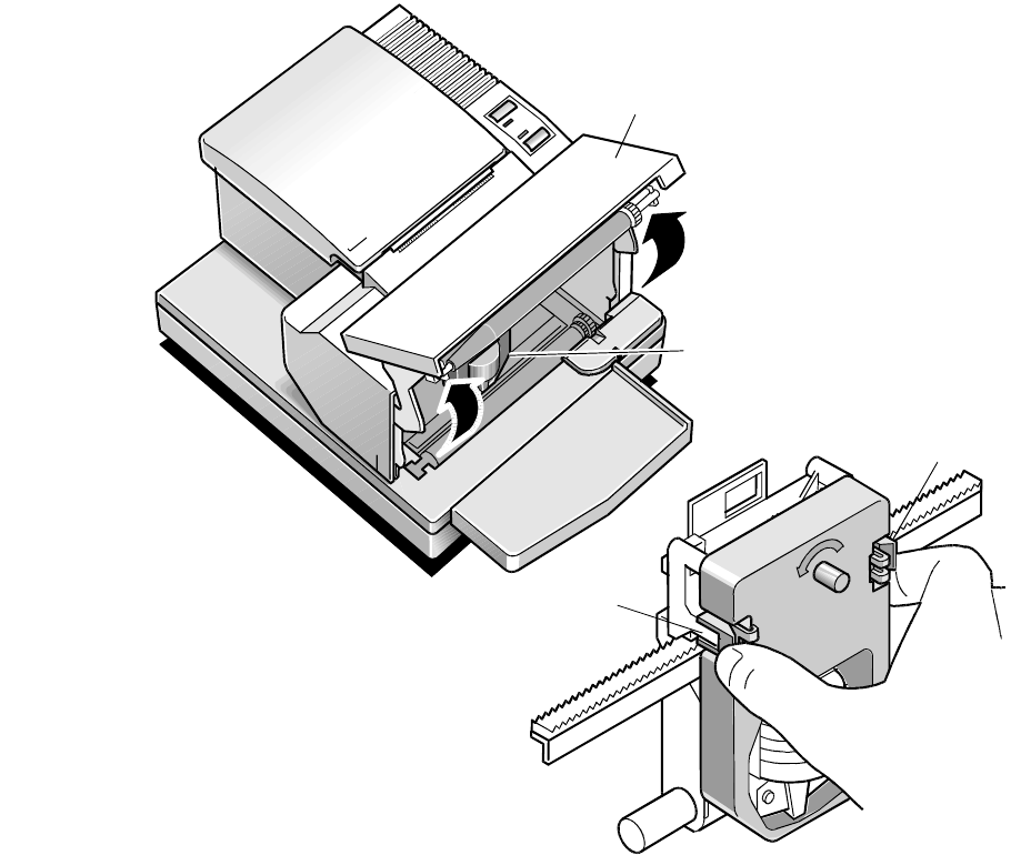
Putting In and Changing the Ribbon Cassette
Change the ribbon cassette when the print is too light or the ribbon is frayed.
Removing the Ribbon Cassette
1. Open the front cover.
2. Squeeze the tabs on the cassette and pull the cassette out of the printer.
Front
Cover
1
Ribbon
Cassette
2
Tab
Tab
7156 Setup and User’s Guide Chapter 2: Setting Up and Using the Printer
September 1998 17
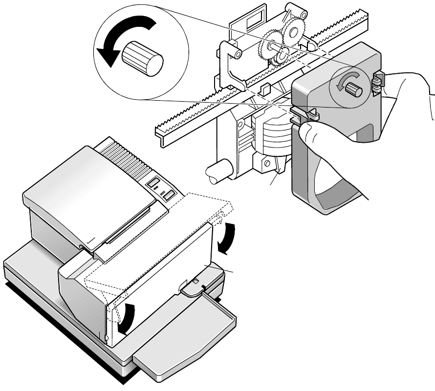
Putting In the Ribbon Cassette
1. Tighten the ribbon by turning the knob in the direction of the arrow.
2. Position the ribbon cassette on the carriage and snap it into place.
Be sure the ribbon is underneath the printhead.
3. Close the front cover.
12
Printhead
3
Front
Cover
Chapter 2: Setting Up and Using the Printer 7156 Setup and User’s Guide
September 199818
Printing on Forms or Checks
There are several types of transactions that require you to insert a form or check
into the printer:
Credit card transaction (some credit card transactions may be printed on the
receipt station and not require any forms)
Multiple-part forms such as credit transactions or merchandise returns
Electronic funds transfers
Check printing (printing the date, payee, and amount on the check face)
Check endorsement
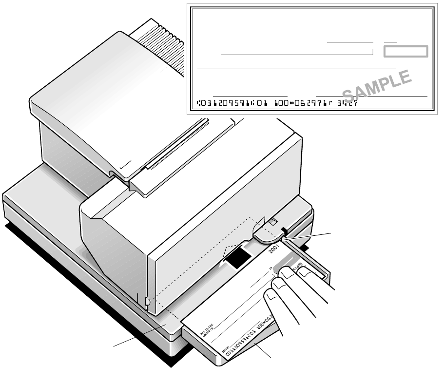
Although the illustration on the facing page shows a check being inserted into the
printer, the instructions apply to any type of form. The 7156 can print on forms up
to five-parts thick. See “Ordering Forms” later in this book for more information
about the type of forms that can be used.
1. Insert the form or check (check shown in the illustration) from the front and
place it on the slip table top first and with the print side up.
If the form is extra long, you may need to insert it from the side.
2. Slide the form or check to the right until it lines up against the guide (wall).
If the form is extra long, you may need to slide it over the form stop to
disengage it. In this case, you will need to mark the slip table for lining up the
form for the proper placement of the print on the form.
3. Slide the form or check toward the back of the printer until it contacts the form
stop (it won't be able to go any further);
Or, align the form or check with any preset mark you may have made on the
slip table for custom forms.
The green LED on the slip table turns on when the form or check is properly
inserted (the form has to cover two sensors on the slip table).
4. Follow the instructions from the host computer.
The printer begins printing.
5. Remove the form or check after it has been fed back out.
6. Follow the instructions from the host computer to finish the transaction.
7156 Setup and User’s Guide Chapter 2: Setting Up and Using the Printer
September 1998 19
Slip
Table
Extended
Slip Table
¦
PAY TO THE
ORDER OF $
DOLLARS
19
MEMO
2001
Check Orientation
Guide
Chapter 2: Setting Up and Using the Printer 7156 Setup and User’s Guide
September 199820
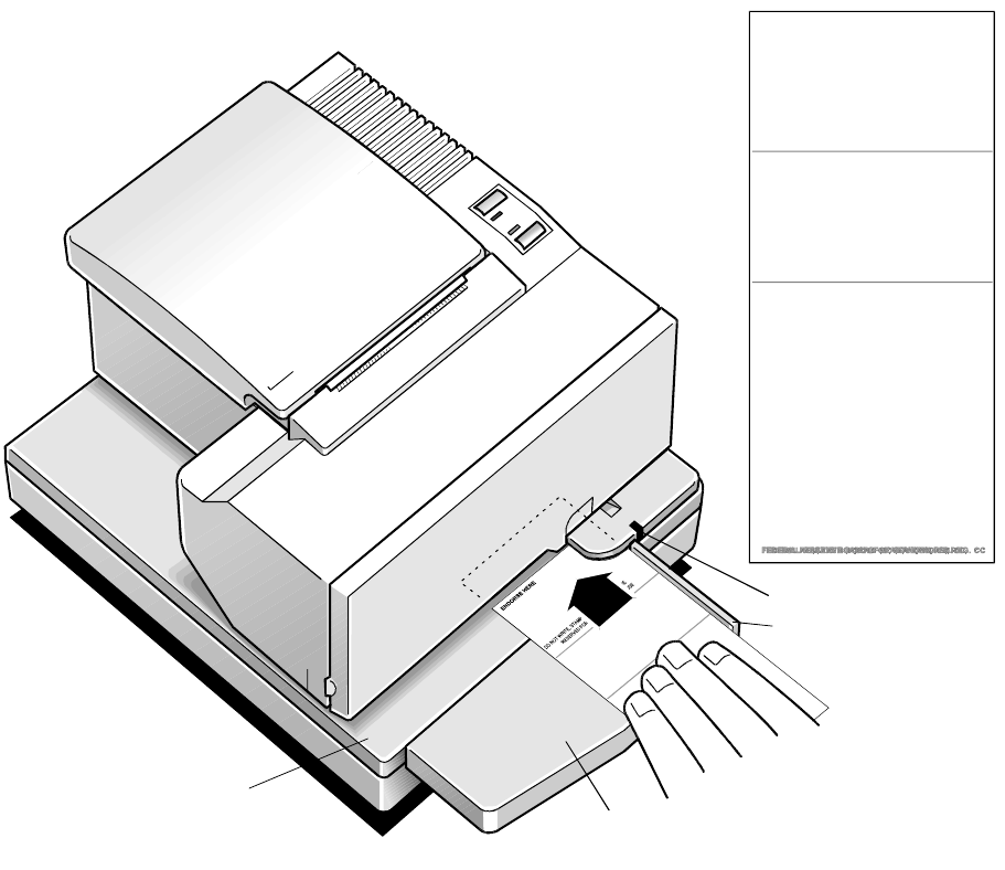
Validating and Verifying Checks
Note: If the MICR check reader feature is present, checks are verified then
validated.
1. Insert the check from the front and place it on the slip table face down as
shown in the illustration on the facing page.
2. Slide the check to the right until it lines up against the guide (wall).
3. Slide the check toward the back of the printer until it contacts the form stop (it
won’t be able to go any further);
Or, align the check with any preset mark you may have made on the slip table.
The green LED on the slip table turns on when the form or check is properly
inserted (it has to cover two sensors on the slip table).
4. Follow the instructions from the host computer.
If the MICR check reader feature is present, the check is fed in and out while
the check numbers are read. If the check is verified as good, it is then
validated. If the check is not verified as good, it is not validated.
Note: Do not hold or keep the check from moving during the MICR check reader
transaction or the check numbers will not be read accurately.
5. Remove the check after it has been fed all the way back out.
6. Follow the instructions from the host computer to finish the transaction.
7156 Setup and User’s Guide Chapter 2: Setting Up and Using the Printer
September 1998 21
Slip
Table Extended
Slip Table
ENDORSE HERE
DO NOT WRITE, STAMP OR SIGN BELOW THIS LINE
RESERVED FOR FINANCIAL INSTITUTION USE
Check Orientation
Guide
LED
Chapter 2: Setting Up and Using the Printer 7156 Setup and User’s Guide
September 199822
Testing the Printer
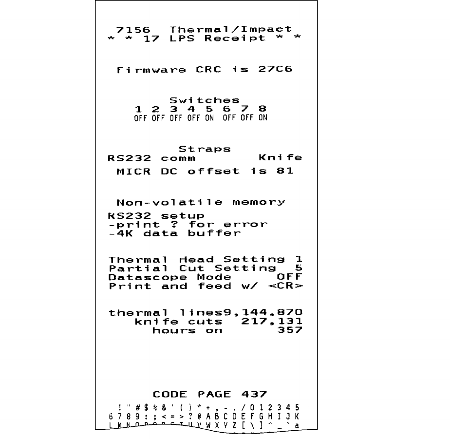
Test the receipt station using the simple tests described here. Additional tests are
described in the “Diagnostics” chapter in the Owner's Guide. The tests print data
about the printer's configuration which is useful to a service representative if there
is a problem. The tests also print the character sets and cut the paper. The tests
continue until you stop them. Several feet of paper can be used to print one pass.
Running the Print Test by Power Cycling the Printer
1. Press the On Line button (or plunger) to put the printer off-line.
Use a paper clip or other pointed object to depress the plunger on models with
that item. The On Line light (green) goes off.
2. Press and hold down the Paper Feed button, then press the On Line button (or
plunger) to begin the test.
3. Let go of the Paper Feed button once the printing begins.
The printer prints the data and character sets until you stop it (see the sample).
4. To stop the test, press the Paper Feed button.
The printer is ready to receive and print data from the host computer.
Running the Print Test by Opening and Closing the Cover
1. Press the On Line button (or plunger) to put the printer off-line.
Use a paper clip or other pointed object to depress the plunger on models with
that item. The On Line light (green) goes off.
2. Open the receipt cover by pulling up on the front left side of the cover.
The Paper Status light (red) comes on indicating the receipt cover is open and
that the printer cannot receive or print data (not that the paper is out).
3. Press and hold down the Paper Feed button while closing the receipt cover.
4. Let go of the Paper Feed button once the printing begins.
The printer prints the data and character sets until you stop it (see the sample).
5. To stop the test, press the Paper Feed button.
The printer is ready to receive and print data from the host computer.
7156 Setup and User’s Guide Chapter 2: Setting Up and Using the Printer
September 1998 23
Sample Print Test
Chapter 2: Setting Up and Using the Printer 7156 Setup and User’s Guide
September 199824
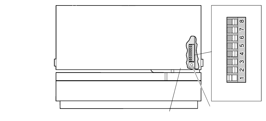
Setting Switches
A group of switches, called DIP switches, are used to set communication
parameters for the RS-232C communication interface. The switches are located
behind the front cover.
Note: The DIP switches are used for other functions. See the “Diagnostics” chapter
in the Owner's Guide for more information.
Caution: The DIP switches are set at the factory to predetermined settings and
should generally not be changed. If you must change the settings do so carefully to
avoid changing other functions.
Before changing any of the switches, first run the print test to print out the current
switch settings on the receipt. See “Testing the Printer” earlier in this book for
instructions on running the print test and for a sample printout.
Front of Printer Reset
Button
Front Cover
Off
Switch 1 is shown
in the OFF position
On
DIP Switch
Note: Switch 1 is shown in the Off position for reference.
Note: Some 7156 models may appear slightly different from what is shown in the
illustration. The procedures are the same for all models unless otherwise noted.

7156 Setup and User’s Guide Chapter 2: Setting Up and Using the Printer
September 1998 25
Use a paper clip or other pointed object to set the switches.
1. Open the front cover.
2. Set the switches to the desired settings shown in the table.
Switch 1 must be set to Off for the on-line mode. Setting switch 1 to On puts
the printer in level 1 diagnostics (setup mode). Changing the other switches in
level 1 diagnostics can change settings that have been pre-set at the factory.
See the “Diagnostics” chapter in the Owner's Guide for more information.
3. Close the cover.
DIP Switch Settings for RS-232C Parameters
Switch Settings Description
1OFF
ON On-line Mode (default)
Level 1 Diagnostics (setup mode)
2OFF
ON DTR/DSR Protocol (default)
XON/XOFF Protocol
3OFF
ON Without Parity (default)
With Parity
4* OFF
ON Odd Parity
Even Parity
5, 6 5
OFF
ON
OFF
ON
6
OFF
OFF
ON
ON
19,200 Baud
9600 Baud (default)
4800 Baud
1200 Baud
*Switch 4 is not used if the parity is disabled (switch 3 set to OFF).
Chapter 2: Setting Up and Using the Printer 7156 Setup and User’s Guide
September 199826
Cleaning the Printer
There is no customer maintenance required for the 7156 printer. However, you
may occasionally clean the cabinet as needed to remove dust and finger marks.
Use any household cleaner designed for plastics, but test it first on a small unseen
area. The cabinet materials and finish are durable and are resistant to the following
items:
Cleaning solutions
Lubricants
Fuels
Cooking oils
Ultraviolet light
If the receipt paper bucket is dirty, wipe it with a clean, damp cloth.
Caution: Do not spray or try to clean the thermal printhead or the inside of the
printer with any kind of cleaner as this may damage the thermal printhead and the
electronics.
If the printhead appears dirty, wipe it with cotton swabs and rubbing alcohol. If
spotty or light printing problems persist after cleaning the thermal printhead,
contact your NCR authorized service organization.
Note: The thermal printhead does not normally require cleaning if the
recommended paper grades are used. If non-recommended paper has been used
for an extended period of time, cleaning the printhead with cotton swabs and
rubbing alcohol will not be of much benefit. See “Chapter 3: Ordering Paper and
Supplies” for recommended paper.

7156 Setup and User’s Guide Chapter 3: Ordering Paper and Supplies
September 1998 27
Chapter 3: Ordering Paper and Supplies
Ordering Thermal Receipt Paper
The 7156 requires “fax grade” thermal paper with the following dimensions:
Diameter Length Width
80 mm max. (3.15 inches) 83 meters (273 ft.) 80 mm ± .5 mm (3.15 ± .008 inches)
The paper must not be attached at the core. Use paper with a colored stripe at the end
to indicate that the paper is running low.
To order thermal receipt paper, contact your sales representative or order from
NCR at the following address or toll free number:
NCR
Media Products Division
9995 Washington Church Road
Miamisburg, OH 45342
Voice: 1(800)543-8130 (toll free), or local listing of Media Products sales office
Chapter 3: Ordering Paper and Supplies 7156 Setup and User’s Guide
September 199828
Ordering Forms
The 7156 prints on single- or multiple-part forms in the slip station (up to five-part
forms). Forms and slips must meet the following requirements:
Front insertion (minimum):
51 mm (2.0 inches) wide
70 mm (2.75 inches) long
Side insertion (minimum):
203 mm (8.0 inches) wide
51 mm (2.0 inches) long
Single-ply forms should be on paper that is greater than 15 pounds
Multiple-part forms (up to five parts) should be no thicker than .406 mm
(.016 inches)
To order forms, contact your sales representative or order from NCR at the
following address or toll free number:
NCR
Media Products Division
9995 Washington Church Road
Miamisburg, OH 45342
Voice: 1(800)543-8130 (toll free), or local listing of Media Products sales office
Ordering Ribbon Cassettes
To order ribbon cassettes, contact your sales representative or order from NCR at
the following address or toll free number:
NCR
Media Products Division
9995 Washington Church Road
Miamisburg, OH 45342
Voice: 1(800)543-8130 (toll free), or local listing of Media Products sales office
Stock Numbers: 198161 (purple ribbon cassette—3 million characters)
198145 (black ribbon cassette—3 million characters)

7156 Setup and User’s Guide Chapter 3: Ordering Paper and Supplies
September 1998 29
Ordering Other Supplies
Contact your sales representative to order the supplies listed in the table.
Item Type Number
Power supply with attached cable to
printer and U.S. power supply cord 7156-K330
Power supply, attached cable 7156-K301
Power supply cord (to outlet) United States
International (no plug)
United Kingdom
S.E.V.
Australia
International (with plug)
7156-K320
7156-K321
7156-K322
7156-K323
7156-K324
7156-K326
RS-232C Communication cables
25-pin (host) to 9-pin
9-pin to 9-pin (3 meters—9.8 ft.)
(3 meters—9.8 ft.) 1420-C001-0030
1416-C057-0030
Extended Slip Table (Standard)
Extended Slip Table (Short) 7156-K280
7156-K281
Cash drawer 7052-K657
(Switchable for
Drawer 1 or
Drawer 2)
Ordering Documentation
Contact your sales representative to order the following documentation:
7156 Thermal Receipt and Impact Slip Printer: Owner’s Guide
(BD20-1436-A)
7156 Thermal Receipt and Impact Slip Printer: Service Guide
(BD20-1437-A) (includes the MICR Operation and Troubleshooting Guide and
the Preventative Maintenance Guide)
Chapter 3: Ordering Paper and Supplies 7156 Setup and User’s Guide
September 199830
BD20-1435-A Issue B 0998 NCR is the name and mark of NCR Corporation
© 1997, 1998 NCR Corporation
Printed in U.S.A.
