NCR 7455 User Manual To The 050205b7 6c6e 45b9 A203 937383bd894f
User Manual: NCR 7455 to the manual
Open the PDF directly: View PDF ![]() .
.
Page Count: 52
- Preface
- Radio Frequency Interference Statements
- Declaration of Conformity
- Site Preparation
- Appendix A: Transient Protection
- Index
NCR 7455 Retail Terminal
Release 1.0
Site Preparation
18427
123
456
789
0
B005-0000-1286
Issue A

The products described in this book are licensed products of NCR Corporation.
NCR is a registered trademark of NCR Corporation.
Pentium is a registered trademark of Intel Corporation.
It is the policy of NCR Corporation (NCR) to improve products as new technology, components, software,
and firmware become available. NCR, therefore, reserves the right to change specifications without prior
notice.
All features, functions, and operations described herein may not be marketed by NCR in all parts of the
world. In some instances, photographs are of equipment prototypes. Therefore, before using this document,
consult with your NCR representative or NCR office for information that is applicable and current.
To maintain the quality of our publications, we need your comments on the accuracy, clarity, organization,
and value of this book.
Address correspondence to:
Manager, Information Products
NCR Corporation
2651 Satellite Blvd.
Duluth, GA 30096
Copyright © 2001
By NCR Corporation
Dayton, Ohio U.S.A.
All Rights Reserved

Site Preparation i
Preface
Audience
This book is written for hardware installer/service personnel, system
integrators, and field engineers.
Notice: This document is NCR proprietary information and is not to
be disclosed or reproduced without consent.
Safety Warnings
This equipment is intended for use with an IT power system with a line-to-
line voltage of 240 V or less.
Fuse Replacement
Caution: For continued protection against risk of fire, replace only
with the same type and ratings of fuse.
Attention: Pour prévenir et vous protéger contre un risque de feu,
remplacer la fusible avec une autre fusible de même type, seulement.
Power Supply Cord Used as Disconnect Means
Caution: The power supply cord is used as the main disconnect
device. Ensure that the socket outlet is located/installed near the
equipment and is easily accessible.
Attention: Le cordon d'alimentation est utilisé comme interrupteur
général. La prise de courant doit être située ou installée å proximité du
matériel et être facile d'accés.
Warning: DO NOT connect or disconnect the transaction printer
while the terminal is powered on. This can result in system or printer
damage.

ii Site Preparation
Lithium Battery Warning
Caution: Danger of explosion if battery is incorrectly replaced.
Replace only with the same or equivalent type as recommended by the
manufacturer. Discard used batteries according to the manufacturer's
instructions.
Attention: Il y a danger d'explosion s'il y a remplacement incorrect de
la batterie. Remplacer uniquement avec une batterie du même type ou
d'un type recommandé par le constructeur. Mettre au rébut les
batteries usagées conformément aux instructions du fabricant.
Peripheral Usage
This terminal should only be used with peripheral devices that are
certified by the appropriate safety agency for the country of installation
(UL, CSA, TUV, VDE) or those which are recommended by NCR
Corporation.
Environmental Consciousness
NCR is demonstrating its concern for the environment by designing an
intelligent power management system into this terminal that operates
efficiently whether the system is in a stand-alone or network
environment.
About this Book
This book provides site preparation information for terminal
components. Peripheral component and AC wiring site preparation
information is NOT provided in this book. The associated reference
documents are listed in the “Related Site Preparation Data” section.

Site Preparation iii
This book contains the information necessary for the preparation of a
site that conforms to NCR specifications. It is very important that the
site complies with the requirements specified in the document because,
once the equipment has been installed, deficiencies in site preparation
or the problems caused by these deficiencies are much more difficult to
detect and correct. Further, failure to comply with these requirements
or to take proper steps to protect equipment against risks identified in
this document may cause serious damage to the equipment and to the
customer’s business.
In addition to the need to comply with the requirements specified,
electrical wiring and mechanical systems must also comply with all
relevant codes, laws, and regulations.
It is important that a customer or his agent who is fully conversant
with the special requirements of electronic equipment prepare the site.
The responsibility of ensuring that the site is prepared in compliance
with this document remains with the customer.
For information and guidance purposes only, a list is provided, in
general terms, of those matters for which the customer is responsible.
This list is not intended to be comprehensive, and in no way modifies,
alters, or limits the responsibility of the customer for all aspects of
adequate site preparation.
NCR staff will be available to answer questions relating to the contents
of this document except where:
• A customer has been notified that a full or partial consultant service
is available and/or that NCR will be willing to undertake a
preliminary or final site survey and
• The customer shall have entered into a formal contract with NCR
for provision of the same.
No comment, suggestion, or advice offered or not offered about
preparation of the site, nor any inspection of the site, whether before of
after preparation, is to be taken as approval of the location of the site
and equipment or its preparation. NCR will not be liable in respect to
any comment, suggestion, or advice given by its staff or in respect to
any failure to give advice.

iv Site Preparation
Finally, only the customer can know the full extent of damage that may
be caused to his business by reason of failure of the equipment which is
to be installed. For this reason, it is the customer’s responsibility to
ascertain the extent of any possible damage to his existing or planned
business, and to effect full insurance in for all eventualities.
References
• NCR 7455 Retail Terminal User’s Guide
(B005-0000-1285)
• NCR 7455 Retail Terminal Service Guide
(B005-0000-1339)
• NCR FitClient User's Guide
(B005-0000-1235)
• NCR 7455 Retail Terminal Parts Identification Manual
(B005-0000-1287)

Site Preparation v
Table of Contents
Introduction.........................................................................1
Interpreting the Model Number.......................................2
Related Site Preparation Data...........................................3
How to Order......................................................................4
Customer Responsibilities 5
AC Store Wiring Requirements 6
LAN Communications 6
System Configuration Diagram 7
Physical Considerations 8
Operating and Service Clearance Requirements............9
Component Dimensions..................................................10
NCR 7455 with Integrated Customer Display
and PCMCIA...............................................................10
NCR 7455 with Integrated Post Customer
Display.........................................................................11
7453-K005 Cash Drawer............................................11
NCR 2189 Cash Drawer.............................................12
NCR 2113 Cash Drawer.............................................12
NCR 7162 Receipt Printer..........................................13
NCR 7194 Thermal Receipt Printer..........................13
NCR 7166 Thermal Receipt/Impact Printer...........14
NCR 7158 Thermal Receipt/Impact Printer...........14
NCR 7196 Thermal Receipt Printer..........................15
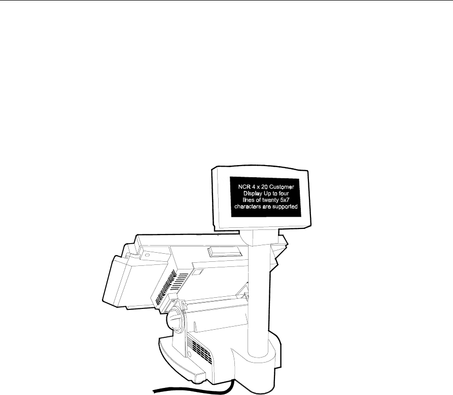
NCR 7455 - 4x20 Remote Post Customer
Display.........................................................................16

vi Site Preparation
NCR 5972 2x20 Remote Post Customer Display....17
NCR 5973 International Remote Post Customer
Display.........................................................................18
NCR 5972 Remote Table-Top Customer Display..19
NCR 2336-K007 External CD-ROM Drive..............20
NCR 2336-K008 USB RS-232 Port Server................20
Component Weights.........................................................21
Ventilation Clearance.......................................................22
Power Requirements........................................................23
Cable Routing Considerations 24
Considerations for Enclosed Installations.....................25
Thermal Test Points...................................................25
Service Access.............................................................25
System Cables 26
Cable Illustrations.............................................................28
Dual Cash Drawer, Y-cable.......................................28
Ethernet, 10/100 Base-T............................................28
USB, 1- or 4-Meter......................................................28
Printer Interface Cables (RS-232) .............................29
NCR 5972 Remote Customer Display and
Adapter Cables...........................................................30
External CD-ROM Cable...........................................31
External Parallel Cable ..............................................31
Automatic Change Dispenser Serial Cable.............32
Power, AC...................................................................32
Environmental Requirements 33
Barometric Pressure..........................................................33
Temperature......................................................................33
Humidity............................................................................33


viii Site Preparation
Revision Record
Issue Date Remarks
A April 01 First issue

Site Preparation ix
Radio Frequency Interference Statements
Federal Communications Commission (FCC)
Information to User
This equipment has been tested and found to comply with the limits for a Class A
digital device, pursuant to Part 15 of FCC Rules. These limits are designed to provide
reasonable protection against harmful interference when the equipment is operated in
a commercial environment. This equipment generates, uses, and can radiate radio
frequency energy and, if not installed and used in accordance with the instruction
manual, may cause harmful interference to radio communications. Operation of this
equipment in a residential area is likely to cause interference in which case the user
will be required to correct the interference at his own expense.
NCR is not responsible for any radio or television interference caused by unauthorized
modification of this equipment or the substitution or attachment of connecting cables
and equipment other than those specified by NCR. The correction of interference
caused by such unauthorized modification, substitution or attachment will be the
responsibility of the user. The user is cautioned that changes or modifications not
expressly approved by NCR may void the user’s authority to operate the equipment.
Canadian Department of Communications
This digital apparatus does not exceed the Class A limits for radio noise emissions
from digital apparatus set out in the Radio Interference Regulations of the Canadian
Department of Communications.
Le présent appareil numérique n’émet pas de bruits radioélectriques dépassant les
limites applicables aux appareils numériques de la classe A prescrites dans le
Règlement sur le brouillage radioélectriques édicté par le ministrère des
Communications du Canada.
Voluntary Control Council for Interference (VCCI)

x Site Preparation
Declaration of Conformity
Manufacturer’s Name NCR Corporation
Manufacturer’s Address NCR Corporation
Retail Solutions Division
2651 Satellite Boulevard
Duluth, GA 30096-5810
Type of Equipment Information Technology Equipment
Model Number Class 7455
Electrical Ratings (Input) 100-240 V, 2.0 A, 50-60 Hz
NCR Corporation, 1700 South Patterson Boulevard, Dayton, OH 45459,
USA, declares that the equipment specified above conforms to the
referenced EU Directives and Harmonized Standards.
EU Directive Harmonized Standard(s)
89/336/EEC (EMC) EN 55022: 1987 (CISPR 22)
EN 50082-1, Part 1: 1992
IEC 801-2: 1984
IEC 801-3: 1984
IEC 801-4: 1988
7
3/23/EEC (Low Voltage)
E
N 60 950: 1992 +A1+A2:1993 +A3:1995
NCR Corporation
Retail Solutions Division— Atlanta
2651 Satellite Boulevard
Duluth, GA 30096-5810
European Contact:
International IP Counsel
206 Marylebone Road
London, NW1 6LY, England
Site Preparation
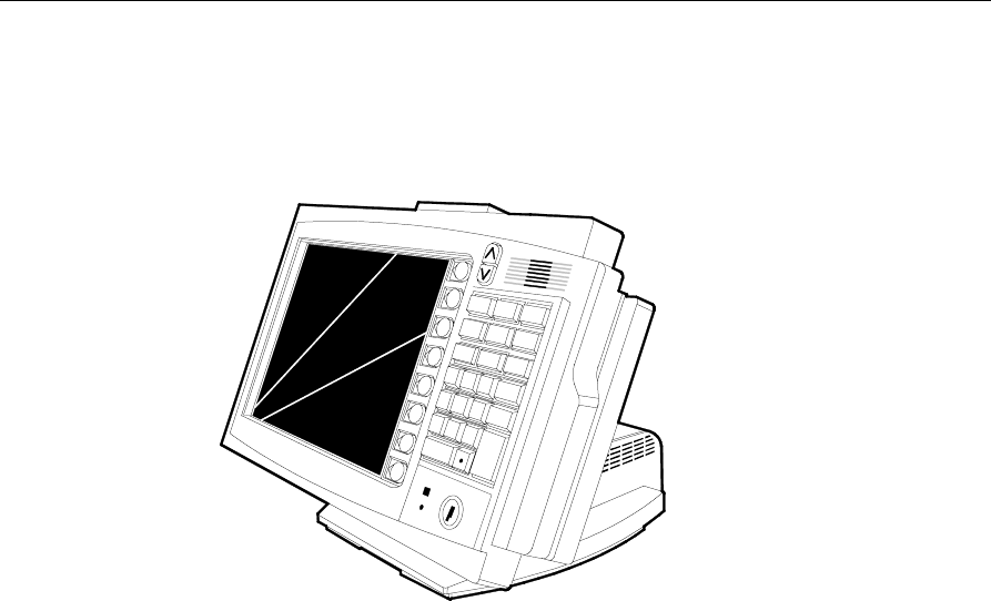
Introduction
18427
123
456
789
0
This document provides the information necessary to prepare a site to
NCR specifications prior to installing a terminal. The site must be
properly prepared before the retail terminal is installed because site
preparation deficiencies may be difficult to detect and correct after
installation.
The terminal consists of separate pieces that may be combined in a
variety of configurations. Certain combinations are mutually exclusive.
You must determine the equipment that will actually be installed
before proceeding with the site preparation.

2 Site Preparation
Interpreting the Model Number
22 = Base Unit with 12.1" LCD
(Release 1)
18043
Language
01 = International English
Power Required
80 = 110 -240 VAC 50/60 Hz
NCR Model 74xx 22 XX 80
Operating System
Processor
01
00 = No OS
01 = Windows
03 = MS/DOS

Site Preparation 3
Related Site Preparation Data
AC Power and Communications Wiring
Title Order Number
NCR Ethernet Communications Wiring Guide BST0-2118-82
NCR Terminal AC Power Wiring Guidelines BST0-2115-53
Peripherals
Title Order Number
NCR 7158 Thermal Receipt/Impact Printer B005-0000-1112
NCR 7162 Thermal Receipt Printer Owner’s Guide B005-0000-1067
NCR 7166 Thermal Receipt/Impact Printer B005-0000-1002
NCR 7194 Thermal Receipt Printer Owner’s Guide B005-0000-1094
NCR 7196 Thermal Receipt Printer B005-0000-1170
NCR 5972 2x20 Customer Display User’s Guide BD20-1372-A
NCR 5973 2x20 (Asian Character Support) Customer
Display User’s Guide BD20-1372-A

4 Site Preparation
How to Order
Information Products are available through several different channels.
You need an order form if you are using fax, e-mail, or mail order.
Order forms are available to NCR personnel through QuickLook. In
QuickLook, click on Forms & Templates, then select Information
Products Order Form.
Web Sites
• http://inforetail.AtlantaGA.NCR.COM (NCR only)
• http://www.info.NCR.COM (Anyone)
Online Order
• Connect System (NCR only)
Phone Order
• 800-543-2010 (US area)
• 622-3727 (VOICEplus)
• 44-181-242-5350 (International)
Fax Order
• 937-445-6245 (US area)
• 44-181-242-5355 (International)
E-Mail
• Information+Products.Publishing@DaytonOH.NCR.COM
(US area)
• Management.Order@unitedkingdom.ncr.com (International)
Mail Order
• NCR Corporation IPP-Dayton
1700 S. Patterson Boulevard
Dayton, OH 45479
USA
• NCR Corporation
915 High Road
North Finchley
London N12 ONH
United Kingdom

Site Preparation 5
Customer Responsibilities
Before the system can be installed, the customer must do or provide
the following:
• When required by NCR, provide the NCR Customer Services
representative with appropriate drawings that indicate:
− Location of the equipment
− Site wiring (power and communications, paths and lengths)
− Location of other equipment that may generate electrical noise,
electromagnetic interference, or heat.
• Make building alterations necessary to meet wiring and other site
requirements
• Provide and install all communications cables, wall jacks, special
connectors, and associated hardware
• Provide and install necessary power distribution boxes, conduits,
grounds, lightning protection devices, and associated hardware
• Make sure all applicable codes, regulations, and laws (including,
but not limited to, electrical, building, safety, and health) are met
• Provide and install auxiliary power or other equipment as required
• Provide storage or service areas as required
• Meet all system/unit environmental requirements
• Provide and install floor coverings and environmental systems that
limit or control static electricity build-up and discharge
In general, keep the NCR equipment area free from dust, smoke, lint,
and other particles. Restrict smoking, eating, and drinking around the
equipment. Avoid locating the equipment near other machines that
generate ink, carbon, and paper dust particles.
Finally, only the customer can know the full extent of the damage that
may be caused to his business by reason of failure of the equipment
that is to be installed. For this reason, it is the customer's responsibility
to ascertain the extent of any such possible damage to his existing or
planned business, and to effect full insurance for all eventualities.

6 Site Preparation
AC Store Wiring Requirements
The customer must provide suitable AC power for the retail terminals,
associated equipment, and devices. A dedicated unswitched power
line dedicated to the NCR equipment installation is recommended.
Refer to the Workstation and Peripherals AC Wiring Guide (BSTO-
2115-53) for store AC wiring requirements. The AC outlet must be
installed near the retail terminal and easily accessible to the operator.
LAN Communications
The terminal supports Ethernet 10/100 Base local area network (LAN)
communication protocol. For Ethernet communications wiring
specifications, refer to the NCR Ethernet Wiring Guide (BST0-2118-82).

Site Preparation 7
System Configuration Diagram
7162
7158
7880
Scanner/Scale
7892
Bi-modal
Presentation
Scanner
123
456
789
0
18984
CRT
Operator or
Customer
Display
5972-1000
Customer
Display
LAN
Ethernet
Cash Drawers
5992
Signature
Capture
7872
Scanner/Scale
RS-232 Peripherals
AC
AC
Only
5945
Electronic
Payment
Terminal
RS-232 Transaction Printers
VGA Parallel/
Serial
LCD
PS/2
KBD
Aux Power
PS/2 or USB
Keyboard
5972-2000
Customer
Display
Serial Only
Cash Drawer
AC
Only
7875
Scanner/Scale
Aux
Power
2189 2113
7837
7455
5973
International
Customer
Display
Aux Power
Parallel
7196 7194
NOTE: 7158 & 7196 connect
to RS-232 or USB
Wedge
NOTE: 7837 connect
to RS-232 or Wedge
7454-K005
7166
**
*
USB
7448
Customer
Display

8 Site Preparation
Physical Considerations
This section presents the following retail terminal information:
• Operating and service clearance requirements
• Display mounting considerations
• Retail terminal and component dimensions
• Component weights
• Airflow requirements
• Power requirements

Site Preparation 9
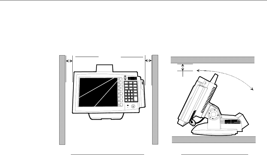
Operating and Service Clearance Requirements
Location Component Distance Reason
Above 7158 Printer 305 mm (12 in.) Clearance to raise printer cover
7162 Printer 197 mm (7.75 in.) Clearance to raise printer cover
7166 Printer 280 mm (11 in.) Clearance to raise printer cover
7194 Printer 228 mm (9 in.) Clearance to raise printer cover
7196 Printer 254 mm (10 in) Clearance to raise printer cover
CRT Displays 50 mm (2 in.) Clearance for CRT tilt
5972-1000
2 x 20 Display 25 mm (1 in.) Clearance for display tilt
All units 153 mm (6 in.) Service clearance
Left Side All units 153 mm (6 in.) Service clearance
Right Side 5972 2 x 20 Display 25 mm (1 in.) Clearance for display rotation
All units 202 mm (8 in.) Service clearance
Front 7162 Printer 127 mm (5 in.) Clearance to open printer door
Drawer unit 330 mm (13 in.) Clearance to open drawer
Behind 7162 Printer 76 mm (4 in.) Clearance to raise printer cover
All units 153 mm (6 in.) Service clearance
10 Site Preparation
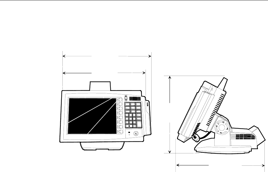
Component Dimensions
NCR 7455 with Integrated Customer Display and PCMCIA
18818
123
456
789
466 mm
(18.3 in.)
380 mm
(15.0 in.)
475 mm
(18.7 in.)
445 mm
(17.5 in.)
Site Preparation 11
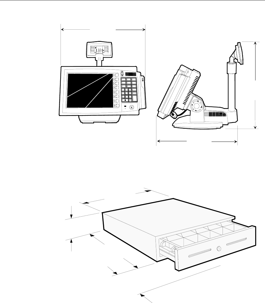
NCR 7455 with Integrated Post Customer Display
12
3
456
789
406 mm
(16.0 in.)
480 mm
(19.0 in.)
475 mm
(18.7 in.)
18817
7453-K005 Cash Drawer
18038
455.6 mm
( 17.94in.)
108 mm
(4.25 in.)
450.9 mm
(17.75 in.)
263.5 mm
(10.375 in.) Operating and Service
Clearance for Drawer

12 Site Preparation
NCR 2189 Cash Drawer
16676
133 mm
(5.25 in.)
330 mm
(13 in.)
(18.25 in.)
Operating and
Service Clearance
for Drawer
464 mm
527 mm
(20.5 in.)
NCR 2113 Cash Drawer
17310
96 mm
(3.75 in.)
400 mm
(15.75 in.)
450 mm
(17.75 in.)
254 mm
(10 in.)
Operating and
Service Clearance
for Drawer
Site Preparation 13
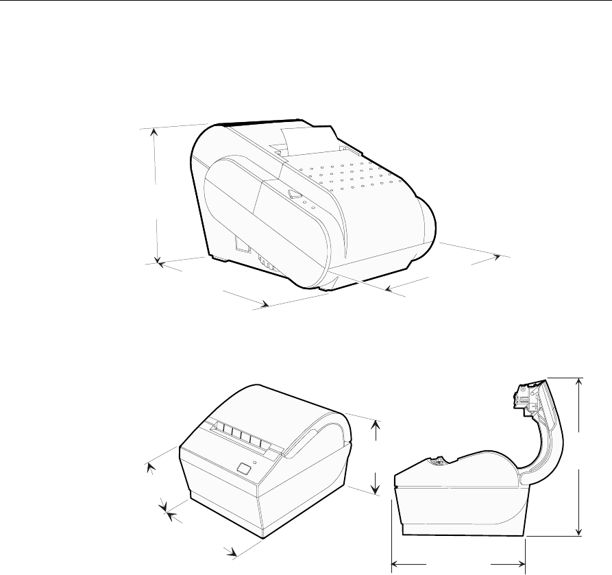
NCR 7162 Receipt Printer
16099
148mm
(5.5 in.)
165 mm
(6.5 in.)
240 mm
(9.45 in.)
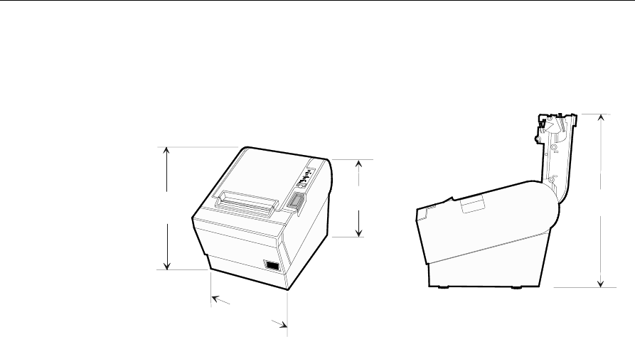
NCR 7194 Thermal Receipt Printer
16492
130 mm
(5.10 in.)
157 mm
(6.20 in.)
85 mm
(3.30 in.)
212 mm
(8.3 in.)
187 mm
(7.4 in.)
14 Site Preparation
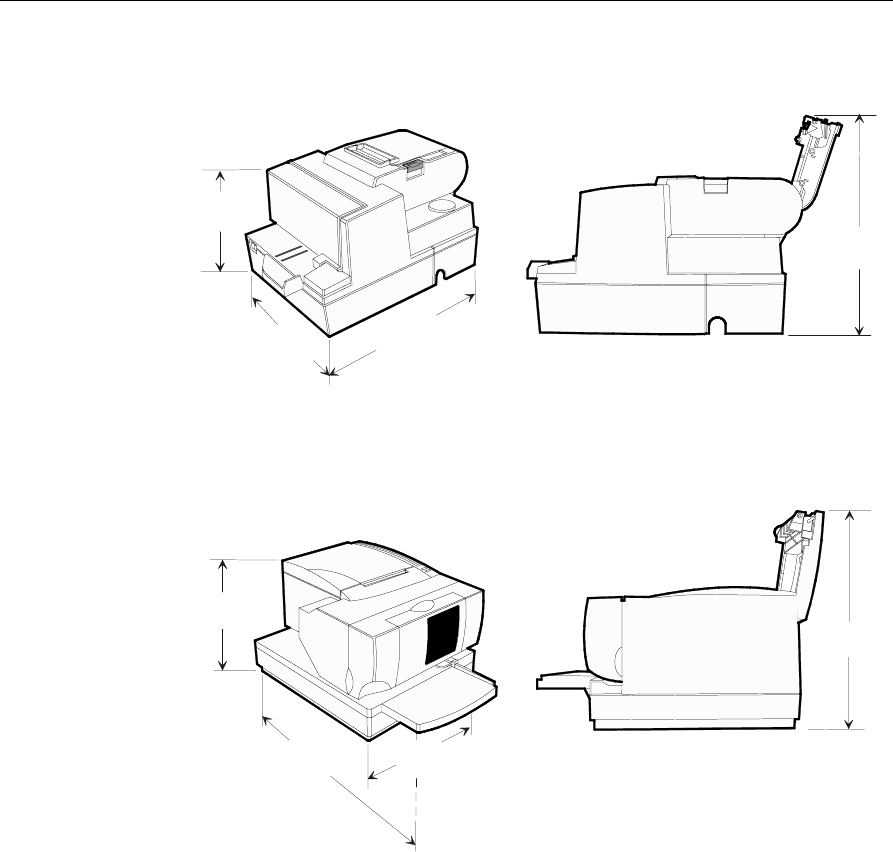
NCR 7166 Thermal Receipt/Impact Printer
171 mm
(6.75 in.)
248 mm
(9.75 in.)
330 mm
(13.00 in.)
280 mm
(11.00 in.)
17308
NCR 7158 Thermal Receipt/Impact Printer
165 mm
(6.50 in.)
336 mm
(13.25 in) 229 mm
(9.00 in)
305 mm
(12.00 in.)
17307
Site Preparation 15
NCR 7196 Thermal Receipt Printer
108 mm
(4.25 in.)
140 m
(5.50 in.)
146 mm
(5.75 in.) 254 mm
(10.00 in.)
17306
16 Site Preparation
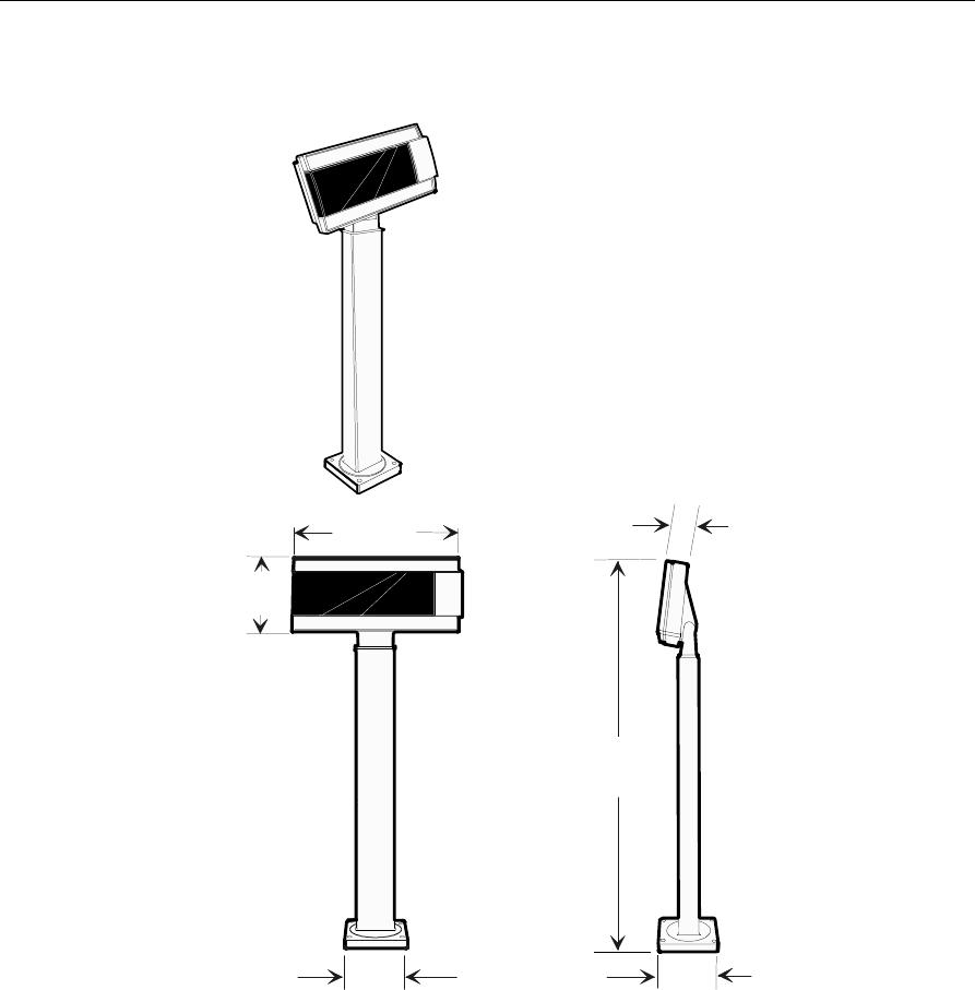
NCR 7455 - 4x20 Remote Post Customer Display
18819
95 mm
(3.75 in.)
506 mm
(22.1 in.)
50 mm
(3.5 in.)
95 mm
(3.75 in.)
180 mm
(7 in.)
110 mm
(4.25 in.)
Site Preparation 17
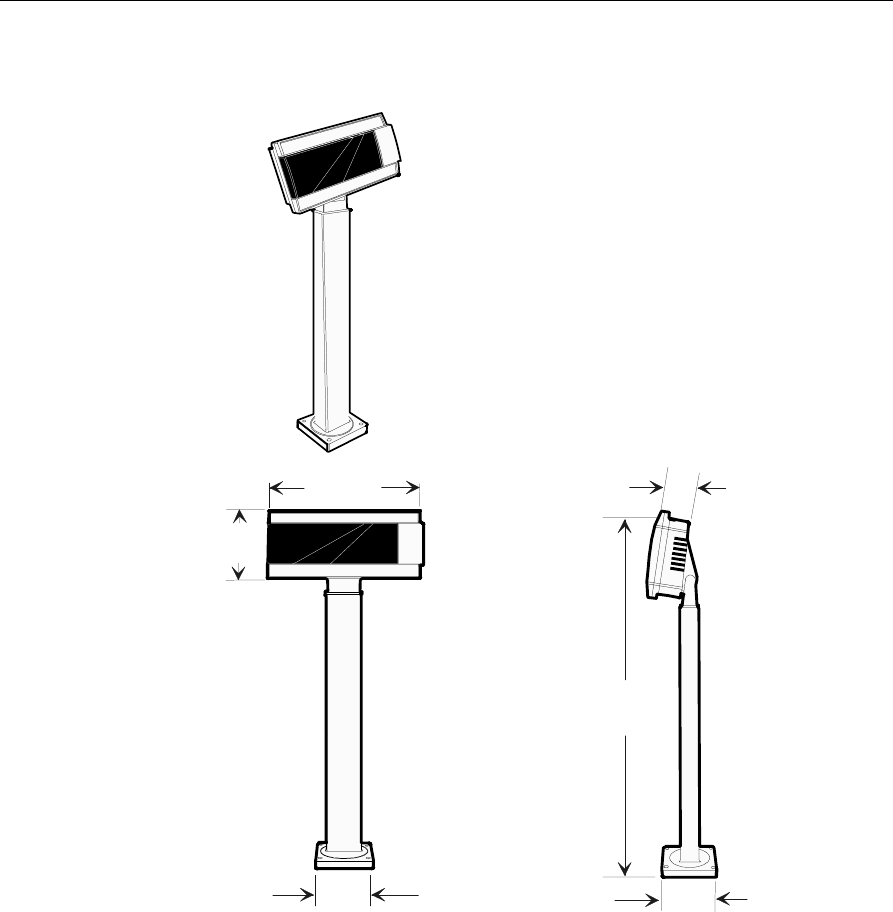
NCR 5972 2x20 Remote Post Customer Display
262 mm
(10.3 in.)
15708
95 mm
(3.75 in.)
506 mm
(22.1 in.)
30 mm
(1.2 in.)
95 mm
(3.75 in.)
119 mm
(4.7 in.)
18 Site Preparation
NCR 5973 International Remote Post Customer Display
350 mm
(13.8 in.)
45 mm
(1.8 in.)
95 mm
(3.75 in.)
95 mm
(3.75 in.)
110 mm
(4.3 in.)
262 mm
(10.3 in.)
17236a
Site Preparation 19
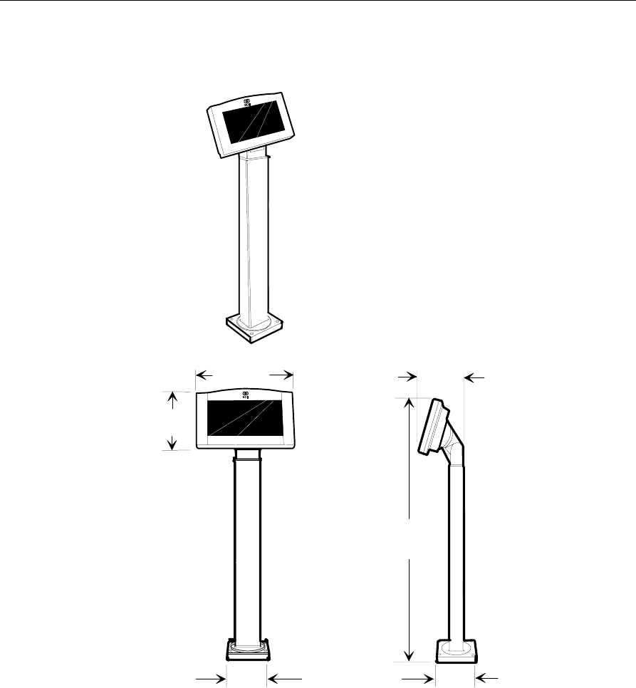
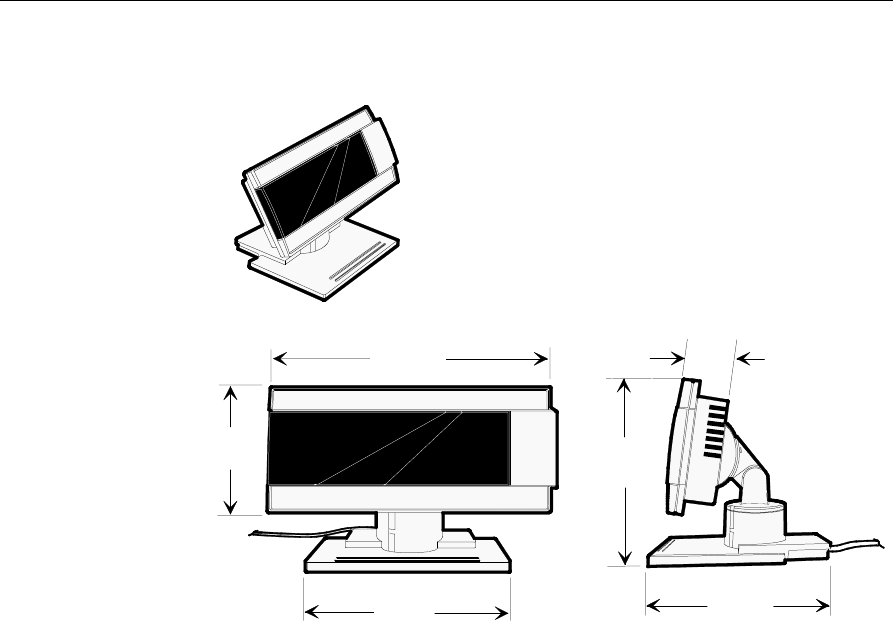
NCR 5972 Remote Table-Top Customer Display
17237
262 mm
(10.3 in.)
158 mm
(6.2 in.)
173 mm
(6.8 in.)
110 mm
(4.3 in.)
45 mm
(1.8 in.)
178 mm
(7.0 in.)
20 Site Preparation
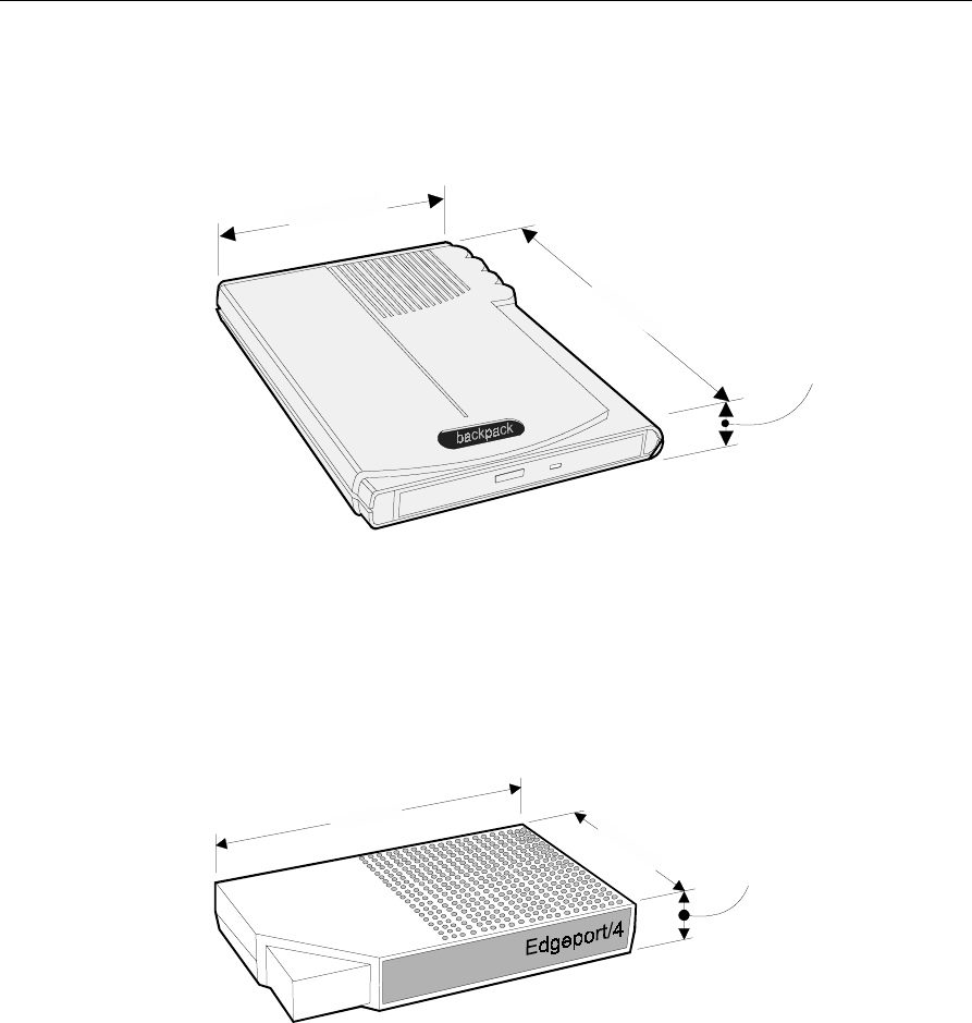
NCR 2336-K007 External CD-ROM Drive
23 mm
(0.9 in.)
155 mm
(6.1 in.)
218 mm
(8.6 in.)
16951
Note: Allow 75 mm (3 in.) clearance in the back of the NCR 2336-K007
External CD-ROM Drive for connector and cable clearance.
NCR 2336-K008 USB RS-232 Port Server
183 mm
(7.2 in.) 111 mm
(4.4 in.) 26 mm
(1.0 in.)
16950

Site Preparation 21
Component Weights
The following table shows the component weights for each integrated
component.
Retail Terminal Components Weight
kg. lbs.
2189 Cash Drawer 9.5 20.9
7453-K005 Cash Drawer 11.4 25.15
7455 4x20 Remote Customer Display 0.7 1.5
7158 Receipt/Impact Printer 4.8 10.5
7162 Receipt Only Printer 1.7 3.8
7166 Receipt/Impact Printer 5.6 12.3
7194 Thermal Receipt Printer 1.3 2.8
7196 Thermal Receipt Printer 1.8 3.4
2336-K007 External CD-ROM Drive 0.6 1.3
2336-K008 USB RS-232 Port Server 0.3 0.6
22 Site Preparation
Ventilation Clearance
Leave the minimum clearances shown below for proper cooling
conditions for the 7455 Class Retail Terminal.
18392
123
456
789
76 mm
(3 in.)
Minimum Vertical ClearanceMinimum Horizontal Clearance
25 mm
(1 in.)

Site Preparation 23
Power Requirements
Core module contain a three-wire, single-phase, selectable 120/240 volt
AC, 95 Watt power supply. The supply powers the retail terminal,
DynaKey, MSR, some scanner, VFD display, keyboard, USB interface,
cash drawer, and PCMCIA cards.
The following tables show operating specifications for the power
supply.
Maximum Input Power Specifications
120 volt 240 volt
Voltage Ranges 90 - 136 VAC 198 - 257 VAC
Frequency 50/60 Hz 50/60 Hz
Current (A) 1.0 0.5
Power (W) 90 90
Power Factor (typical) 0.48 0.38
Typical Power Requirements
System Retail Terminal Condition Amps Watts KVA
120 Volt 7455 Soft OFF 0.39 20.9 0.04
7455 Idle (Power ON) 0.59 35.3 0.07
7455 Active with 4x20
display ON 0.66 38.3 0.08
240 Volt 7455 Soft OFF 0.25 18.5 0.05
7455 Idle (Power ON) 0.38 37.6 0.10
7455 Active with 4x20
display ON 0.43 40.6 0.11
24 Site Preparation
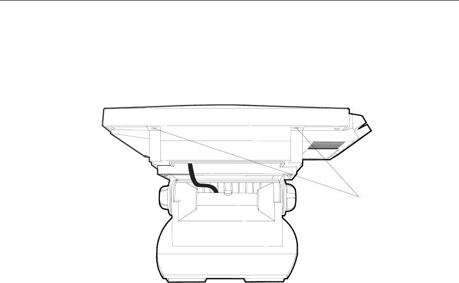
Cable Routing Considerations
External cables can be routed out the back of the Table-Top Mount.
The internal cable connectors on the terminal are located on the
underside of the Core Module under the Cable Cover.
18365
Screws (2)
Site Preparation 25
Considerations for Enclosed Installations
Thermal Test Points
With the terminal installed in the enclosure, verify that the temperature
does not exceed 45o C (115o F) in the operating environment. Test the
temperature at the rear access panel covering the CD-ROM and hard
drive.
18820
Note: For terminal servicing information refer to NCR 7455 Retail
Terminal Hardware Installation & Service (B005-0000-1285).
Service Access
The enclosure must provide access to certain locations for service
purposes.

26 Site Preparation
System Cables
Cable Type Cable Name NCR Part No. Corp. ID No Approximate
Cable Lengths
Cash Drawer Dual Drawer, Y cable 497-0409394 1416-C372-0006 0.6 m/2 ft
Communications Ethernet, 10/100Base-T 497-0008623
(Unshielded)
USB 497-0415949 1416-C528-0010 1 m/3 ft
USB 497-0415950 1416-C528-0040 4 m/13 ft
Displays Remote Customer Display
(Parallel Interface) 497-0418248 1416-C628-1000 4 m/13 ft
2x20 Customer Display
(RS-232 Interface) 497-0415249 1416-C629-1000 4 m/13 ft
Parallel I/F Cable
(adapter cable) 497-0411000 1416-C472-0006 0.6 m/2 ft
Power U.S. – Straight 006-1009037 1416-C325-0030 3 m/10 ft
U.S. – Twist-lock 250-0023191 1416-C419-0030 3 m/10 ft
Intl. – Straight ‘BM’ Power 006-8601010 1416-C323-0030 3 m/10 ft
Intl. 006-1012224 1416-C411-0030 3 m/10 ft
SEV – Straight ‘BM’ Power 230-0113955 1416-C408-0030 3 m/10 ft
UK – Straight ‘BM’ Power 006-8601012 1416-C321-0030 3 m/10 ft
UK – Rectangular 230-0113956 1416-C409-0030 3 m/10 ft
Australia – Straight ‘BM’
Power 006-8601019 1416-C322-0030 3 m/10 ft
Japan – Twist-lock, Straight
‘BM’ Power 008-0218043 1416-C420-0030 3 m/10 ft
Printer Interface 7194/7158 Printer 497-0408349 1416-C359-0007 0.7 m/2 ft.
497-0407943 1401-C266-0040 4 m/13 ft
497-0409379 1416-C266-0152 15.2 m/50 ft
7162 Printer 497-0407427 1416-C337-0010 1 m/3.3 ft
497-0407429 1416-C337-0040 4 m/13 ft
497-0407430 1416-C337-0152 15.2 m/50 ft
497-0409379 1416-C266-0152 15.2 m/50 ft

Site Preparation 27
Cable Type Cable Name NCR Part No. Corp. ID No Approximate
Cable Lengths
Printer Extender
Drop Cables
(7453-K641)
7162/7166/7196
Printer/Workstation 497-0411815 1416-C417-0040 4 m/13 ft
7194 Printer 497-0411816 1416-C418-0040 4 m/13 ft
Printer Power
Supply 7194 Printer 497-0405945 1416-C286-0040 4 m/13 ft

28 Site Preparation
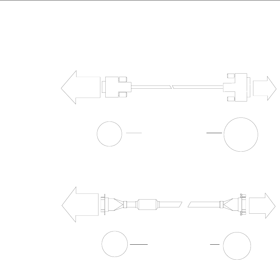
Cable Illustrations
Dual Cash Drawer, Y-cable
15808
51 mm
(2.0 in.)
16 mm
(0.625 in.) Access Hole Diameters
Cash
DWR. #1
Cash
DWR. #2
497-0409394
Ethernet, 10/100 Base-T
16298
19 mm
(.75 in.)
19 mm
(.75 in.) Access Hole Diameters
Modular
8-Pin
Plug
Modular
8-Pin
Plug
497-0008623
USB, 1- or 4-Meter
Site Preparation 29
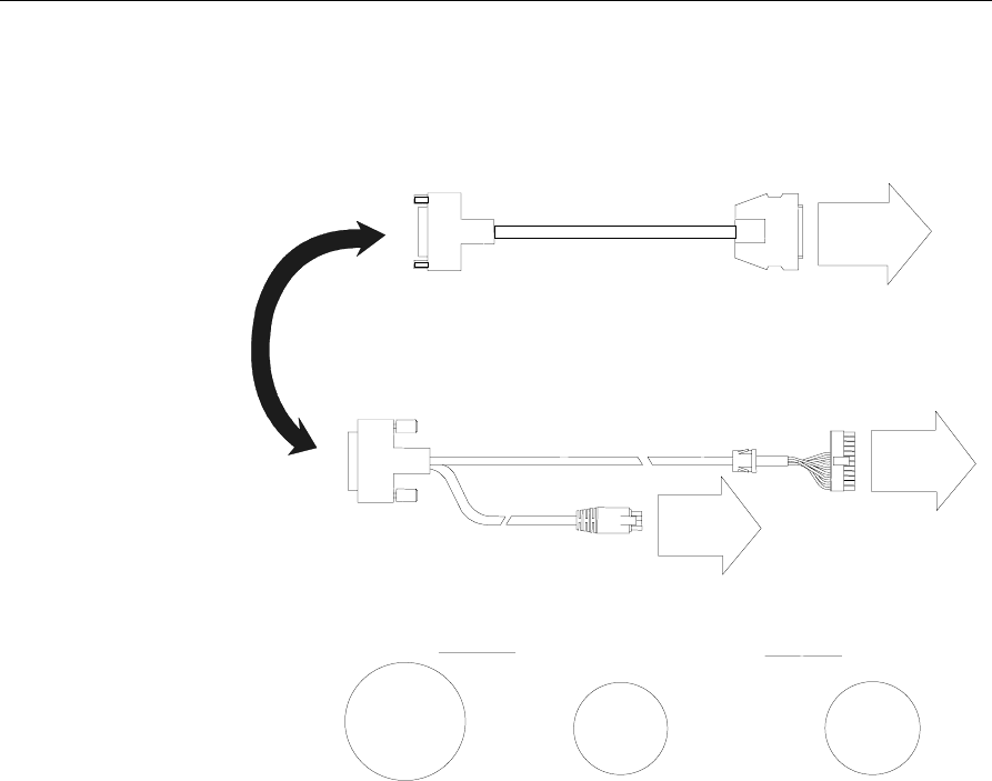
Printer Interface Cables (RS-232)
7162/7166/7196
13224
63.5 mm
(2.5 in.)
38 mm
(1.5 in.) Access Hole Diameters
Printer
497-0407427 - 1 m
497-0407429 - 4 m
497-0407430 - 15 m
Workstation
RS-232 Port
9-pin
D-shell
Receptacle
25-pin
D-shell
Plug
7194/7158
13223
38 mm
(1.5 in.)
38 mm
(1.5 in.) Access Hole Diameters
Printer
Workstation
RS-232 Port
9-pin
D-shell
Receptacle
9-pin
D-shell
Receptacle
497-0408349 - 0.7 m
497-0407943 - 4 m
497-0409379 - 15 m
30 Site Preparation
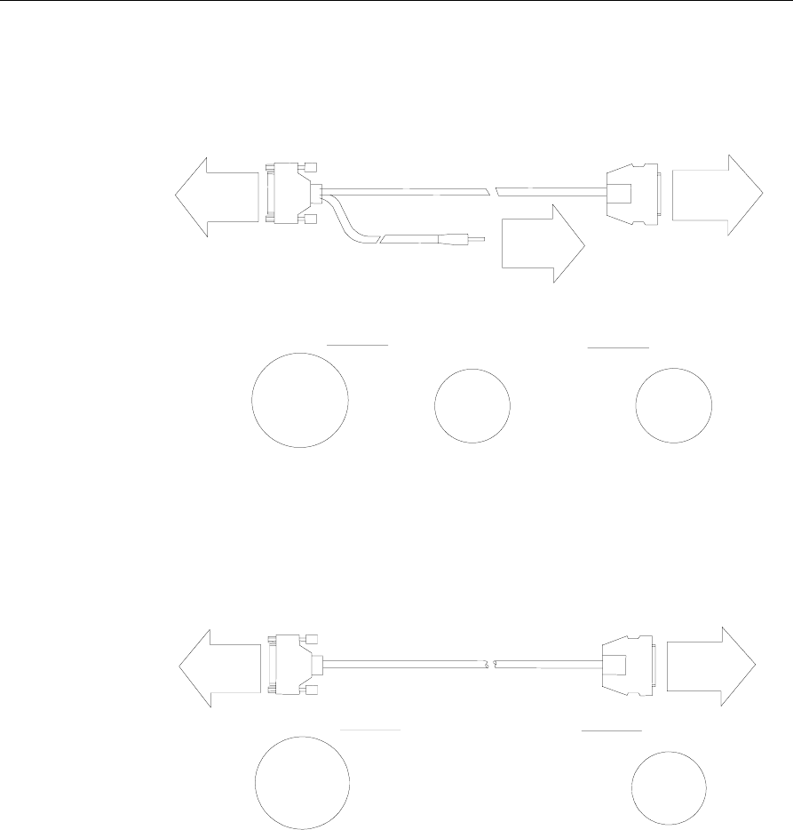
NCR 5972 Remote Customer Display and Adapter Cables
1
6291
T
o
P
ower
B
rick
8
-pin
M
icrofit
R
eceptacle
T
o
C
ustomer
D
isplay
To
C
ust. Display
P
ort
4
97-0405676 - 4 M
1
416-C278-0040
2
5-pin
D
-Shell
R
eceptacle
2
4-pin
M
icrofit
R
eceptacle
2
5 mm
(
1.0 in.)
5
7.1 mm
(
2.25 in.)
A
ccess Hole Diameters
1
9 mm
(
0.75 in.)
P
arallel I/F Cable
4
97-0411000 - 0.6 M
Site Preparation 31
External CD-ROM Cable
1
6959
T
o CD-ROM
P
ower
C
onnector
S
MK
2
mm Plug
T
o CD-ROM
P
arallel
C
onnector
4
97-0413011 - 0.6 M
1
416-C464-0006
2
5-pin
D
-Shell
R
eceptacle
2
8-pin
S
ub-Miniture
D
-Plug
3
1 mm
(
1.25 in.)
5
7 mm
(
2.25 in.)
A
ccess Hole Diameters
1
2 mm
(
0.5 in.)
T
o 7455
C
ust. Display
P
ort
External Parallel Cable
1
7390
T
o CD-ROM
P
arallel
C
onnector
4
97-0411000-0.6 M
1
416-C472-0006
2
5-pin
D
-Shell
R
eceptacle
2
8-pin
S
ub-Miniture
D
-Plug
3
1 mm
(
1.25 in.)
5
7 mm
(
2.25 in.)
A
ccess Hole Diameters
T
o 7455
C
ust. Display
P
ort
32 Site Preparation
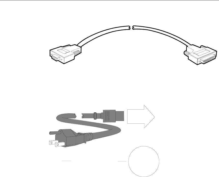
Automatic Change Dispenser Serial Cable
18056
497-0404832
9-Pin
D-shell
Receptacle
25-pin
D-shell
Plug
P2
1
6
5
9
P1
1
14
13
25
Power, AC
15405
45 mm
(1.75 in.)
Access Hole Diameter
Workstation
006-1009037

Site Preparation 33
Environmental Requirements
Barometric Pressure
The 7455 Retail Terminal is designed to operate within the following
barometric pressure conditions:
• Maximum operating altitude: 3000 m (9843 ft)
• Operating range of pressure: 105 kPa to 69 kPa (15.2 lb/in. to 10.0
lb/in.)
Temperature
The 7455 Retail Terminal is designed to operate over the temperature
ranges shown below. Continuous operation must be avoided, however,
at or near the temperature extremes, or in locations where temperature
changes exceed the temperature restrictions.
Temperature Parameter Restriction
Operating 5oC to 45oC (41oF to 113oF), dry bulb
Storage -10oC to 50oC (14oF to 122oF), three months
Shipping -40oC to 60oC (-40oF to 140oF), one week
Dew Point 26oC (79oF) maximum
Humidity
The 7455 Retail Terminal is designed to operate within the humidity
ranges shown below. Continuous operation must be avoided, however,
at or near the humidity limits, or in locations where humidity changes
exceed the humidity restrictions. In no case should the 7455 Retail
Terminal be subjected to condensation.
Humidity Type Restriction
Relative 10% to 90%
Maximum change rate 10%/60 minutes
Storage 10% to 90% relative humidity, three months
Shipping 5% to 95% relative humidity, one week

34 Site Preparation

Appendix A: Transient Protection
AC Power Line Transient Protection
In the process of power distribution, transient electrical energy
(including, but not limited to, lightning strikes, intermittent short
circuits, and switching transients) can be introduced onto power lines.
Such transient energy can be very damaging to electronic hardware,
and can also cause data corruption. Under these circumstances, NCR
recommends the use of AC power transient suppressors. Such
protection devices are intended to guard against power line transients
that can result in hardware damage and various system or program
errors.
Improvement of any deficiencies in power quality is a customer
responsibility. Malfunction and/or component failure as a result of
power quality problems is not covered by the NCR Maintenance
Agreement. NCR accepts no liability for any such occurrence or for its
consequences.
When power transient suppression is required, the suppressors used
should meet the following minimum requirements:
• Dissipate energy to match the appropriate application categories as
defined by IEEE Standard 587.
• Be of the voltage limiting (clipping), or tracking filter type. The
suppressor must not clamp the voltage to zero, and must self-
recover after the passage of the transient. The suppressor may be of
the hybrid type construction that makes use of various technologies
in order to meet speed and dissipation requirements.
• Upon failure, exhibit a positive indication of its failure such as a
blown fuse or tripped breaker.

A-2 Appendix A: Transient Protection
• Be listed by the accepted safety organization for the country
involved (UL, CSA, VDE, ETL, and so on) and the installation must
conform to local, state, and national electrical codes and
regulations.
Data Line Transient Protection
The nature of the transient phenomenon may extend to the data
communication lines connected to this equipment. It is the
responsibility of the customer to install and connect a data line
transient suppression system to correct or prevent any deficiencies.
Such systems must meet the following minimum requirements:
• Be of the voltage limiting type and must self-recover after passage
of the transient.
• Insert less than 5 ohms resistance and minimal inductive and
capacitive loading at the operating frequency for non-MIRLAN
data lines, in order to avoid signal degradation.
• Be installed in accordance with all applicable local, state, and
national electrical codes and regulations.
Note: In certain countries, NCR is able to supply both power and data
line transient suppressors as well as a comprehensive line of power
conditioning equipment. For application data, contact your NCR
Customer Services Division Representative.

Index A-i
Index
—2—
2336-K007 External CD-ROM Drive, 20
2336-K008 USB RS-232 Port Server, 20
—4—
4x20 Remote Customer Display, 16
—5—
5972-1000 Remote Customer Display, 17
5973 International VFD Customer
Display, 18, 19
—7—
7158 Thermal Receipt/Impact Printer, 14
7161 Thermal Receipt Printer, 13
7166 Thermal Receipt/Impact Printer, 14
7194 Thermal Receipt Printer, 13
7196 Thermal Receipt Printer, 15
7453-K005 Cash Drawer, 11
—A—
ACD Serial Cable, 32
—C—
Cable Illustrations, 28
Cable Routing Considerations, 24
Cables, 26
CD-ROM Drive, 20
Clearance Requirements, 9
Communications, 6
Configuration Diagram, 7
Customer Display, 18, 19
Customer Responsibilities, 5
—D—
Dimensions, 10
Dimensions and Weight
Weight, 21
Dual Cash Drawer, Y-cable, 28
—E—
Environmental Requirements, 33
Barometric Pressure, 33
Humidity, 33
Temperature, 33
Ethernet, 10/100 Base-T, 28
External CD-ROM Cable, 31
External Parallel Cable, 31
—H—
Humidity, 33
—M—
Maximum operating altitude, 33
Model Number, 2

ii Index
—N—
NCR 2113 Cash Drawer, 12
NCR 2189 Cash Drawer, 12
—O—
Operating range of barometric pressure,
33
—P—
Power requirements, 23
Printer
7158 Thermal Receipt/Impact Printer,
14
7161 Thermal Receipt Printer, 13
7166 Thermal Receipt/Impact Printer,
14
7194 Thermal Receipt Printer, 13
7196 Thermal Receipt Printer, 15
Printer Interface Cables (RS-232), 29
—R—
Remote Customer Display, 17
Remote Customer Display and Adapter
Cables, 30
RS-232 Port Server, 20
—S—
Service Access, 25
—T—
Temperature, 33
Thermal Test Points, 25
—U—
USB, 28
—V—
Ventilation Clearance, 22
—W—
Weight, 21
Wiring Requirements, 6

B005-0000-1286 April 2001 Printed on recycled paper
