MANUAL

Color TFT-LCD Monitor
User’s Manual
NLM18S / NLM19S
NLM18S / NLM19S

NLM18S / NLM19S
OPERATION MANUAL
Color TFT- LCD Monitor
CONTENTS
……………4,5
……………6
…8
.……9,10,11
……………12
SAFETY PRECAUTIONS
SUPPLIED ACCESSORIES
PREPARATION
LOCATION OF USERS CONTROL
MONITOR INSTALLATION
STATUS INFORMATION
……………………7Cable Connection
OSD USAGE
……15
……………………16
BEFORE CALLING FOR REPAIR SERVICE
NLM18S / NLM19S
Available PC VGA Mode
SPECIFICATIONS
…..….……………13,14
…………17
INTERNATIONAL STANDARDS ……18
………..…3NOTES ON LCD MONITORS

NLM18S / NLM19S
Notes On LCD Monitors
Color TFT- LCD Monitor
1.The LCD panel used in this monitor is a very high technology product with 3,932,160 thin film
transistors, giving you fine picture details. Occasionally, a few non-active pixels may appear on the
screen as a fixed point of red, green, blue, white or black. Please note that this does not indicate a
defective panel.
2. Set your resolution to 1280 x 1024 pixels at 60Hz refresh rate for optimum display quality.
The display may become a bit blurry when you set the resolution to other than 1280 x1024. Please
note that this does not indicate a defective product.
3. The screen surface is very soft. Do not rub, touch or tap the screen surface with sharp object such
as pen or pencil. This contact may scratch or damage the screen. These damages are not covered
under the warranty.
4. Turn your computer OFF before installing your new monitor.

Improper use can result in electric shock and/or fire. In order to prevent potential danger,
please observe the following instructions when installing, operating and cleaning the
product. To ensure your safety and prolong the service life of your color
TFT-LCD monitor product, please read the following precautions carefully before
using the product.
JAll operating instructions must be read and understood before the product is operated.
JThese safety and operating instructions must be kept in safe place for future reference.
JAll warnings on the product and in the instructions must be observed closely.
JAll operating instructions must be followed.
JDo not use attachments not recommended by the manufacturer. Use of inadequate
attachments can result in accidents.
JThis product must be operated on a power source specified on the specification label. If you are
not sure of the type of power supply used in your home, consult your dealer or local power
company. For units designed to operate on batteries or another power source, refer to the
operating instructions.
JThe power cords must be routed properly to prevent people from stepping on them or objects
from resting on them. Check the cords at the plugs and product.
JDo not overload AC outlets or extension cords. Overloading can cause fire or electric shock.
JNever insert an object into the product through vents or openings. High voltage flows in the
product, and inserting an object can cause electric shock and/or short internal parts. For the
same reason, do not spill water or liquid on the product.
JDo not attempt to service the product yourself. Removing covers can expose you to high voltage
and other dangerous conditions. Request a qualified service person to perform servicing.
JIf any of the following conditions occurs, unplug the power cord from the AC outlet, and request a
qualified service person to perform repairs.
a. When the power cord or plug in damaged.
b. When a liquid was spilled on the product or when objects have fallen into the product.
c. When the product has been exposed to rain or water.
d. When the product does not operate properly as described in the operating instructions.
Do not touch the controls other than those described in the operating instructions.
Improper adjustment of controls not described in the instructions can cause damage,
which often requires extensive adjustment work by a qualified technician.
e. When the product has been dropped or damaged.
f. When the product displays an abnormal condition. Any noticeable abnormality in the
product indicates that the product needs servicing.
JIn case the product needs replacement parts, make sure that the service person uses
replacement parts specified by the manufacturer, or those with the same characteristics and
performance as the original parts. Use of unauthorized parts can result in fire, electric shock
and/or other danger.
JUpon completion of service or repair work, request the service technician to perform safety
checks to ensure that the product is in proper operating condition.
JWhen mounting the product on a wall or ceiling, be sure to install the product according to the
method recommended by the manufacturer.
SAFETY PRECAUTIONS
4

JUnplug the power cord from the AC outlet before cleaning the product. Use a damp cloth to clean
the product. Do not use liquid cleaners or aerosol cleaners.
JUnplug the power cord from the AC outlet if you do not use the product for considerably long time.
JDo not use the product near water, such as bathtub, washbasin, kitchen sink and laundry tub,
swimming pool and in a wet basement.
JKeep the product away from direct rays of the Sun-light.
JDo not place the product on an unstable cart, stand, tripod or table. Placing the product on an
unstable base can cause the product to fall, resulting in serious personal injuries as well as
damage to the product. Use only a cart, stand, tripod, bracket or table recommended by the
manufacturer or sold with the product. When mounting the product on a wall, be sure to follow the
manufacturer's instruction. Use only the mounting hardware recommended by the manufacturer.
JWhen relocating the product placed on a cart, it must be moved with the utmost care.
Sudden stops, excessive force and uneven floor surface can cause the product to fall from the cart.
JThe vents and other openings in the cabinet are designed for ventilation. Do not cover or block
these vents and openings since insufficient ventilation can cause overheating and/or shorten the life
of the product. Do not place the product on a bed, sofa, rug or other similar surface, since they can
block ventilation openings. This product is not designed for built-in installation; do not place the
product in an enclosed place such as a bookcase or rack, unless proper ventilation is provided or
the manufacturer's instructions are followed.
JThe LCD panel used in this product is made of glass. Therefore, it can break when the product is
dropped or applied with impact. Be careful not to be injured by broken glass pieces in case the LCD
panel breaks.
JKeep the product away from heat sources such as radiators, heaters, stoves and other heat-
generating products (including amplifiers).
SAFETY PRECAUTIONS(Continued)
5
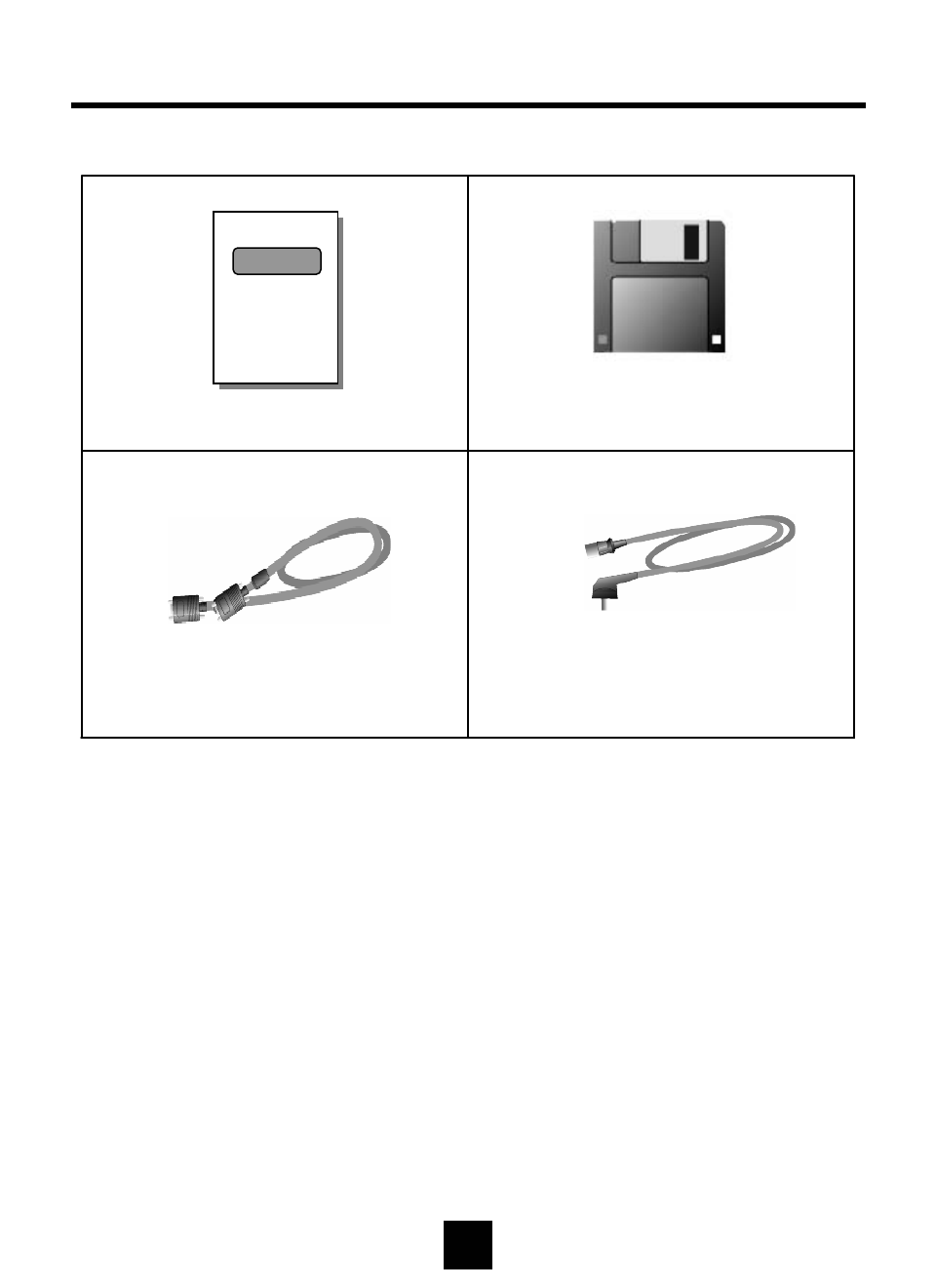
Make sure the following accessories are provided with the product.
User’s Manual (*1)
AC Cord (*1)
PC VGA Cable(*1)
6
Monitor Driver Diskette (x1)
SUPPLIED ACCESSORIES
NLM18S / NLM19S
NLM18S / NLM19S
Color TFT-LCD Monitor
User’s Manual
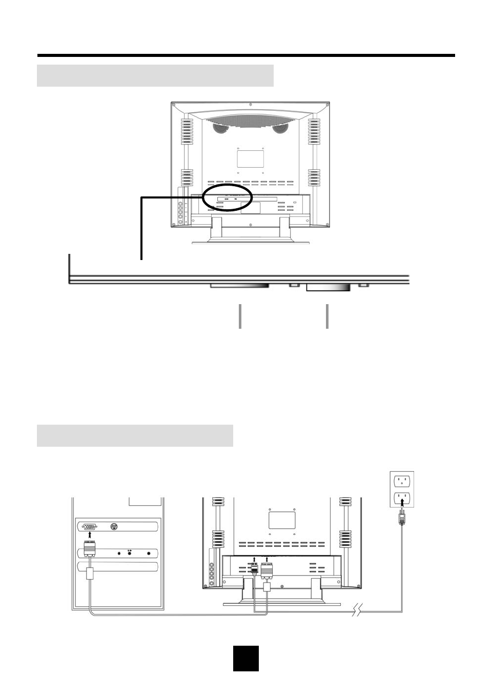
1Power Input : AC 100~240Vac
2Analog RGB : PC VGA Cable
VGA & Power Cable Connection
7
Cable Connector Description
PREPARATION – Cable Connection
12
1
2
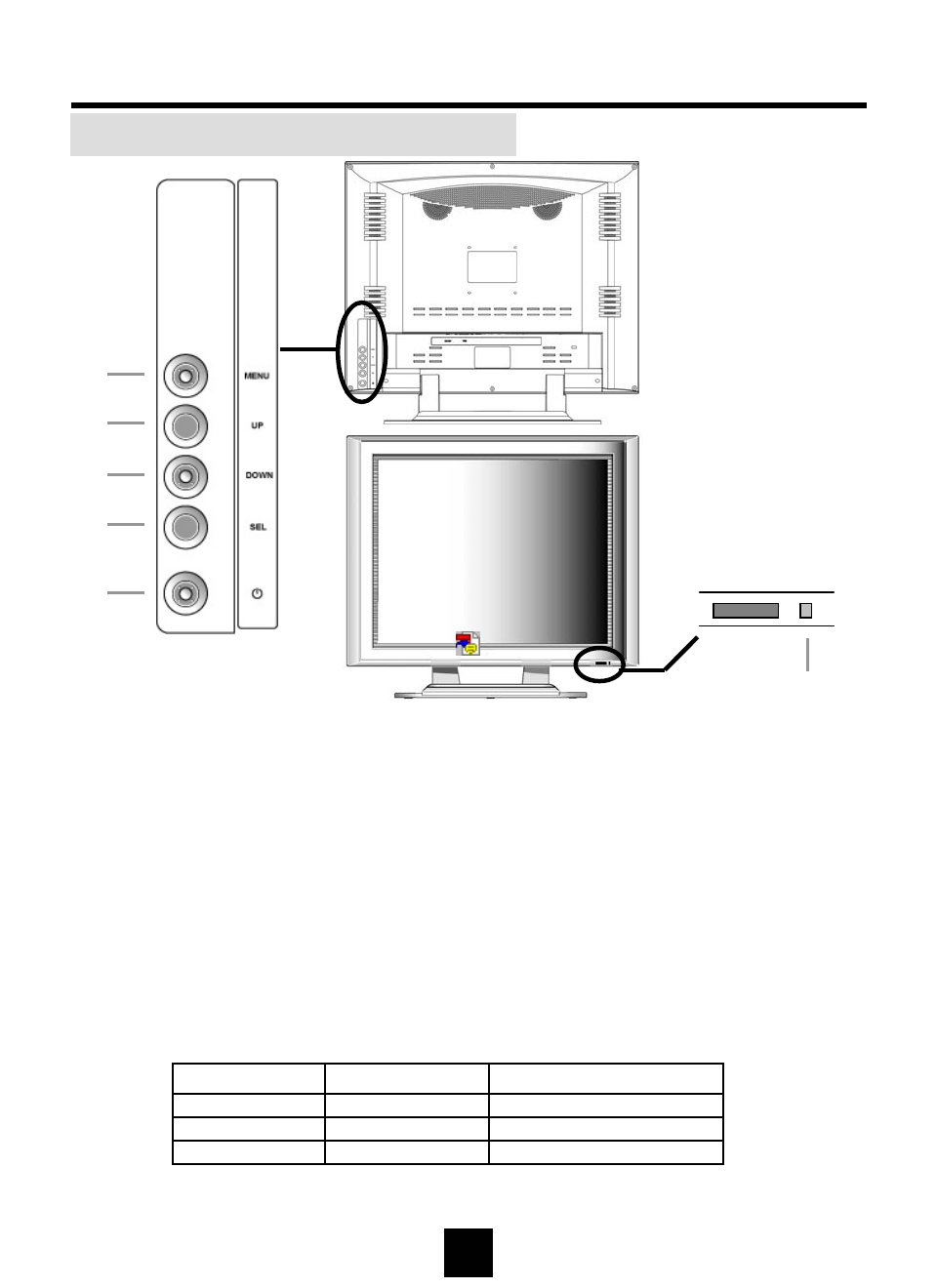
Control Panel on the front of main unit
8
LOCATION OF CONTROL PANEL
1MENU : Display menu window / Exit from sub menu
Exit from OSD window
2UP : Adjust setting value (Increase) / Move up
3DOWN : Adjust setting value (Decrease) / Move down
4SEL : Select menu item on OSD window
“Hot key for auto adjustment”
5POWER : On / Off
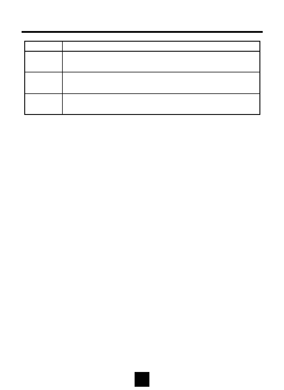
6POWER LED :
Rear
Front
LED 꺼짐
Orange LED
Green LED
LED Status
-
No signal (PC Mode)
-
Remak
Sleep Mode
Power On
On
Power Off
1
2
3
4
5
6
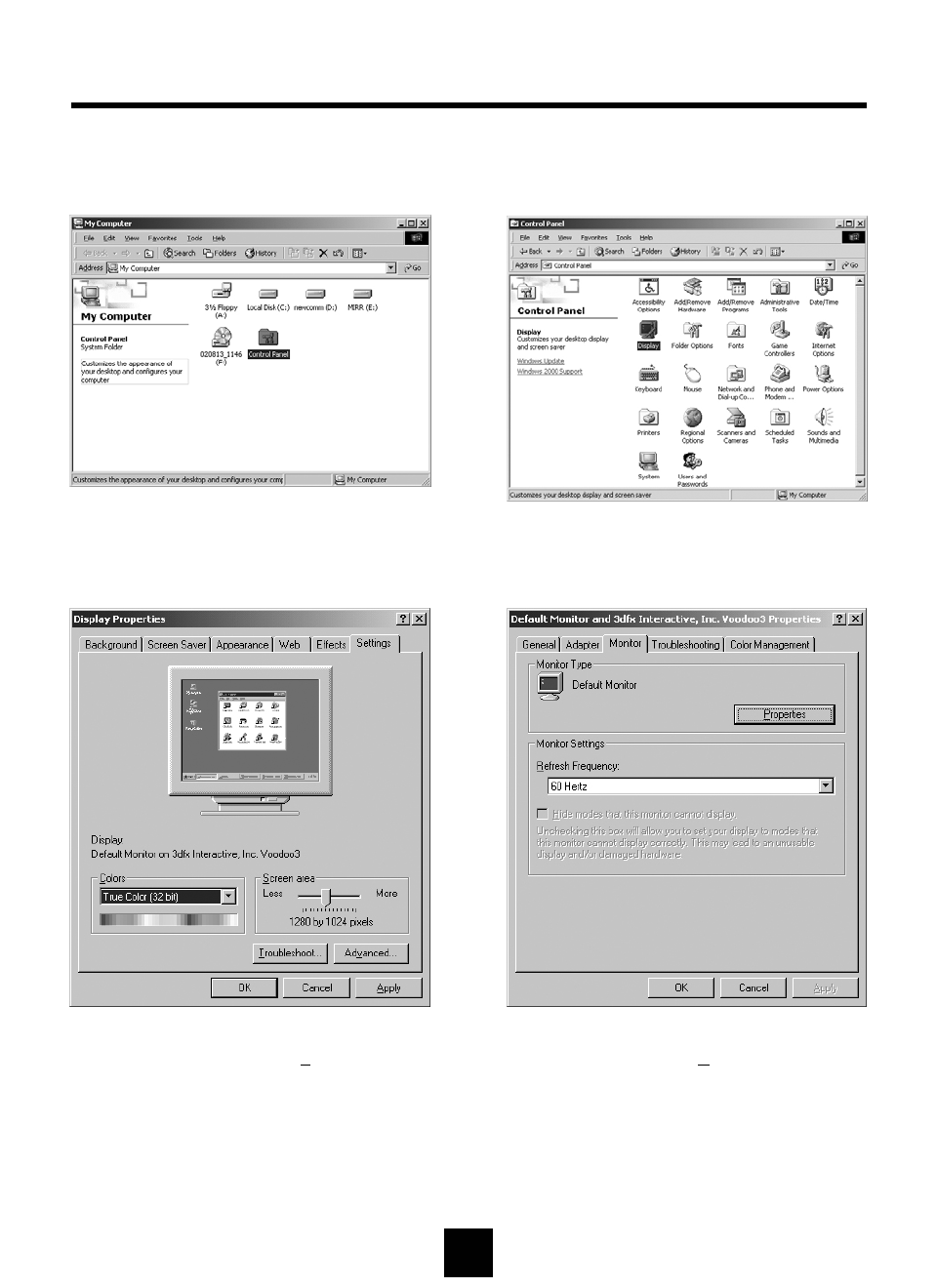
3Select [Settings] in [Display Properties]
window and then click [Advanced...].4Select [Monitor] in the window shown
above and then click [Properties].
1Double click [Control Panel ] icon
from [My Computer] folder. 2Double click [Display] icon from
[Control Panel] folder.
MONITOR INSTALLATION
9
The instruction below is for Windows 2000
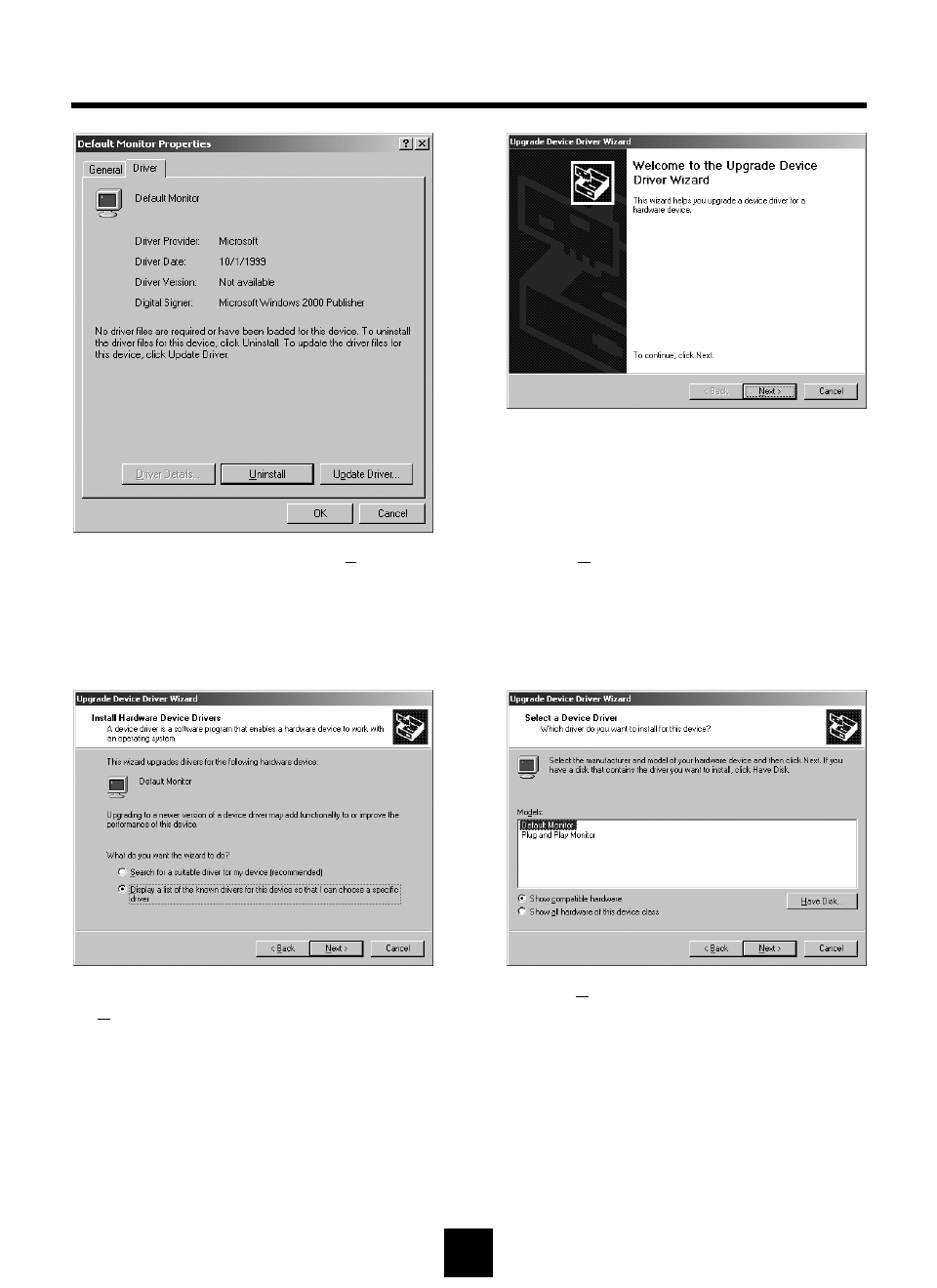
5Select [Driver] and then click [Update
Driver...].6Click [Next>].
8Click [Have Disk...].
MONITOR INSTALLATION(Continued)
10
7Select the second list and then click
[Next>].
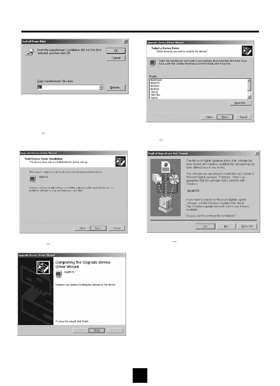
10 Choose Your Monitor Model, then click
[Next>] to proceed to the next step.
MONITOR INSTALLATION(Continued)
11 Click [Next>] to start installation.
13 Click [Finish].
(Be sure the screen shows correct model name.)
11
12 Click [Yes] to proceed to the next step.
9Click [Browse…] to select CD-ROM drive.
12
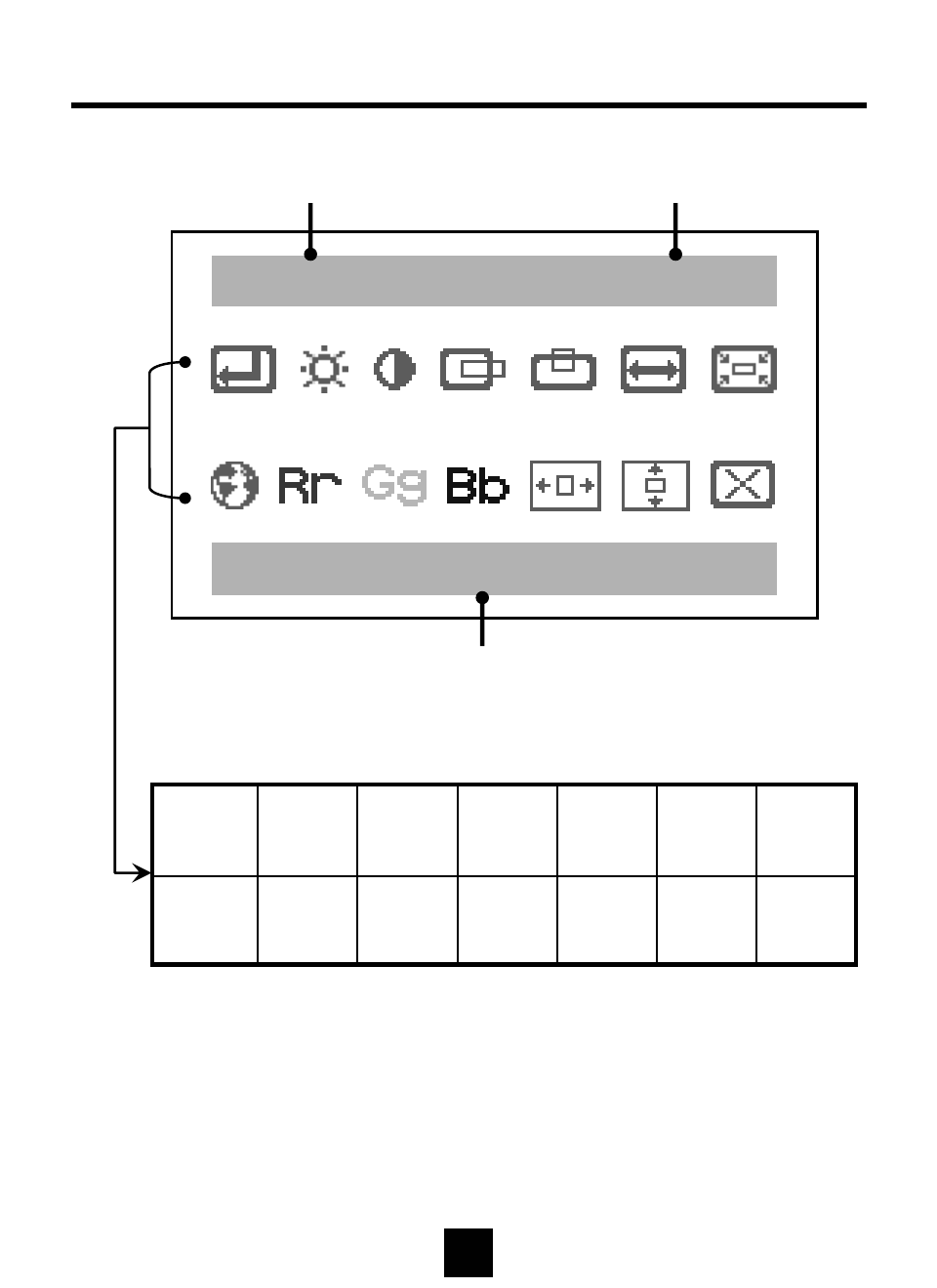
STATUS INFORMATION
Resolution
Selected Menu Icon Name
1280 X 1024 75Hz
Auto Config
Reset
OSD V
Position
OSD H
Position
BlueGreenRedLanguage
PhaseClock
V
Position
H
Position
ContrastBrightness
Auto
Config
Vertical Frequency
13
OSD USAGE
JAdjust Green Color by using DOWN or UP buttons.
Green
JAdjust Red Color by using DOWN or UP buttons.
Red
JSelect the language of OSD menu
- English / Français / Italiano / Deutschland / Korean
Language
JWhen noise remains on the screen after operating the auto adjustment,
adjust it by using Down or UP buttons.
Perform this adjustment just in the case of having horizontally unmatched
picture after operating the auto adjustment
Phase
JAdjust horizontal size by using Down or UP buttons.
Do not make manual adjustment when the picture is in its
Normal shaped or you will create problem on it.
Clock
V Position
H Position
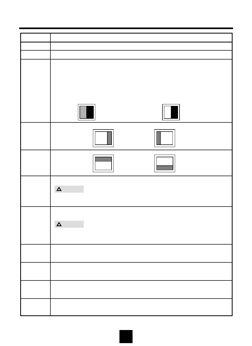
Operate the auto adjustmentAuto Config
JContrast is ratio of luminance between black and white.
JWhen contrast is reduced (DOWN button), the luminance of
white is reduced and the display becomes darker.
JWhen contrast is increased(UP button), the luminance of white is
increased and the display becomes clear.
DOWN Button : Decrease Contrast UP Button : Increase Contrast
Contrast
JAdjust Blue Color by using DOWN or UP buttons.
Blue
DOWN : Decrease Brightness UP : Increase Brightness
Brightness
OperationMenu
Caution
!
Caution
!
deo
Video Video
DOWN Button:
Move Left UP Button :
Move Right
DOWN Button
Move Down UP Button :
Move Up
Vid
BWW B
14
OSD USAGE (continued)
JAdjust OSD H Position by using DOWN or UP buttons.
OSD
H Position
JAdjust OSD V Positon by using DOWN or UP buttons.
OSD
V Position
JReset values to initial value at time of forwarding at the factory.Reset
OperationMenu
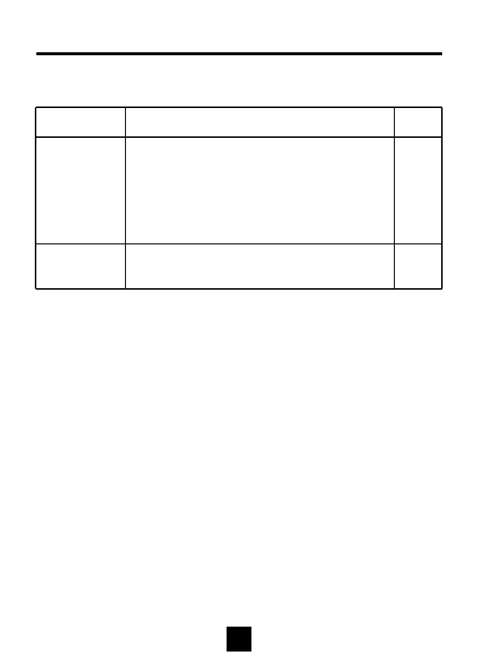
Before calling for repair service, check the following items for possible remedies
to the encountered symptoms.
Problem Check below
There is no
picture • Make sure the power cord is properly inserted in the
power outlet.
• Make sure the main power button of the main unit is on.
• Make sure the signal cable is free of connections.
• Make sure whether the power of an external input device
is on.
• Fluorescent lamp may have reached the end of service life.
Reference
Pages
7
8
7
-
16
Picture is not
clear • Operate the auto adjustment
• Adjust the Frequency and the Phase.
8
13
15
BEFORE CALLING FOR REPAIR SERVICE…
16
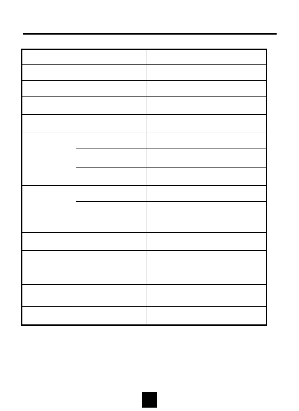
Input
NLM18S : 7.0 Kg (w/o accessories)
NLM19S : 7.2 Kg (w/o accessories)
Weight
30~80 KHzH-Frequency
PC Signal
(Analog RGB) 56~75 HzV-Frequency
0.7Vp-pSignal Level
1280 * 1024, SXGAResolution
485 x 383 x 57 mm ,
174 mm (Stand Depth)
W*H*D mmSize
Max. 3 WattOff- Mode
NLM18S : Max. 45 Watt
NLM19S : Max. 45 Watt
On
Power Consumption
AC100~240V, 50/60HzPower Voltage
NLM18S : 18.0", 457.34 mm
NLM19S : 19.0”, 481.92 mm
Diagonal Length
NLM18N : 357.12(H) x 285.696(V) mm
NLM19N : 376.32(H) x 301.056(V) mm
Actual Display Size
Amorphous Si TFT-LCDType
Panel
NLM18S : 160º (H) / 160º (V)
NLM19S : 170º (H) / 170º (V)
Viewing Angle
NLM18S : 400 : 1
NLM19S : 500 : 1
Contrast Ratio
250 cd/m2(nit)Brightness
16,777,216 Colors (Full Color)Color
SPECIFICATIONS
Color TFT LCD Monitor
SPECIFICATIONS
17
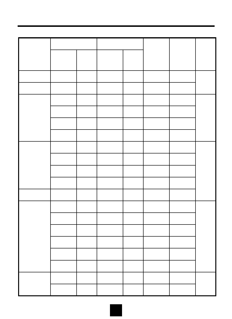
VESA78.750P60.02P75.03
IBM75.000P57.52P72.10
MAC64.000N48.78N60.00
Polarity
Frequency
(KHz)
Polarity
Frequency
(Hz)
SXGA
XGA
SVGA
VGA
DOS
Remark
VESA
VESA
MAC
VESA
VESA
MAC
VESA
VESA
VESA
VESA
VESA
VESA
MAC
VESA
IBM
IBM
Standard
Type
25.175N31.47N70.09640 x 350
28.322N31.47P70.09720 x 400
25.175N31.47N59.94
640 x 480
30.240N35.00N66.67
31.500N37.86N72.81
31.500N37.50N75.00
36.000N/P35.16N/P56.25
800 x 600
40.000P37.88P60.32
50.000P48.08P72.19
49.500P46.88P75.00
57.283N49.73N74.55832 x 624
65.000N48.36N60.00
1024 x 768
75.000N56.48N70.07
80.000N60.24N74.93
108.000P63.98P60.02
1280 x 1024
135.000P79.98P75.03
Horizontal
Pixel Rate
(MHz)
Vertical
Resolution
Available PC VGA Mode

FCC
CAUTION : Any changes or modifications in construction of this device which are not expressly
approved by the party responsible for compliance could void the user's authority to operate the
equipment.
NOTE: This equipment has been tested and found to comply with the limits for a Class B digital
device, pursuant to Part 15 of the FCC Rules. These limits are designed to provide reasonable
protection against harmful interference in a residential installation. This equipment generates,
uses and can radiate radio frequency energy and, if not installed and used in accordance with the
instructions, may cause harmful interference to radio communications. However, there is no
guarantee that interference will not occur in a particular installation.
If this equipment does cause harmful interference to radio or television reception, which can be
determined by turning the equipment off and on, the user is encouraged to try to correct the
interference by one or more of the following measures:
- Reorient or relocate the receiving antenna.
- Increase the separation between the equipment and receiver.
- Connect the equipment into an outlet on a circuit different from that to which the
receiver is connected.
- Consult the dealer or an experienced radio/TV technician for help.
CE
EN55022 "Limits and methods of measurement of radio disturbance characteristics of information
technology equipment (ITE)"
EN55024 "Information technology equipment - Immunity characteristics - Limits and methods of
measurement"
EN61000-3-2 "Limits for harmonic current emissions (equipment input current <= 16A per phase)"
EN61000-3-3 "Limitation of voltage fluctuations and flicker in low-voltage supply system for
equipment with rated current <= 16A“
EN60950 “Safety for information technology equipment including electrical buisness equipment”
18
INTERNATIONAL STANDARDS