User Manual

2版 2015 年12 月 NIX-M01-14007
GX410NC/GX420NC
Installation, Setting Manual
3

4
Read me
Thank you very much for purchasing "GX410NC/GX420NC" (under called
“this product”).
Before operating this product, please read this installation and setting
manual carefully and use it properly.
Especially, please make sure read the “Precautions” ( P.6-10) carefully
and operate the product definitely and safely.
After having read it, please keep the manual leaflet at hand and check
any time.
Decline
All rights of this manual are reserved.
The contents of this manual may change without notice.
The company names, product names in this manual are either
trademarks or registered trademarks of their respective owners.
The U-SIM card is not included in this product.
When use U-SIM card to communicate, the communication charges of
the carriers is required.
5
●Please keep this manual carefully.
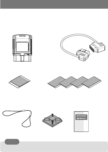
Checking the suppled items
Before use this product, please check the supplies items as below.
Please check with the dealer if any shortage.
□GX410NC/GX420NC device
□Socket extension cable
(sample)
□Device fixing double-stick
tape(sample)
□Fixing tape 4pcs(sample)
□Safety strap
(sample)
□Convex base
(sample)
□Installation,
setting manual
(this book)
Please
6
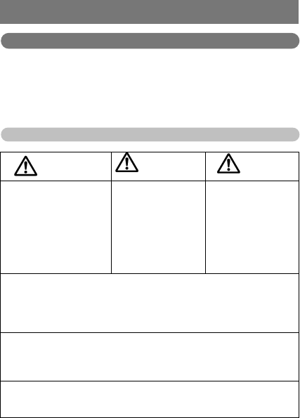
Precautions
Please read carefully for your safety use
●This “precautions” is to describe the compliance rules to predict and
prevent the
harm to the user of this product and other person, and the damage to
the property.
●The compliance rules describe as the following divisions.
Explanation of the indication
This indication is to
show “the
imminent possible
contents that death
or serious injury to
person occur”.
This indication is to
show “the
possible contents
that death or
serious injury to
person occurs”.
This indication is to
show “the contents
that person may be
damaged or
property may be
damaged”.
※1 ”Serious injury” means blindness, injury, burn (high and low
temperature), electrification, fracture, addiction etc. , which after
effect remain or need for hospitalization or long-tern doctor’s visit to
treatment.
※2 ”Injury” means injury, burn (high and low temperature),
electrification, which no need for hospitalization or long-tern doctor’s
visit to treatment.
※3”Property damage” means extended damage to house, household
article, domestic animal, pet.
Dangerous
Waring
Caution
7
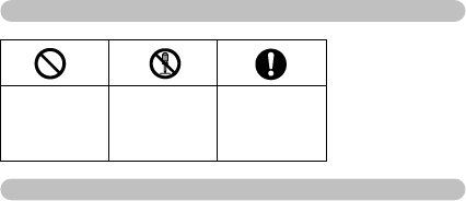
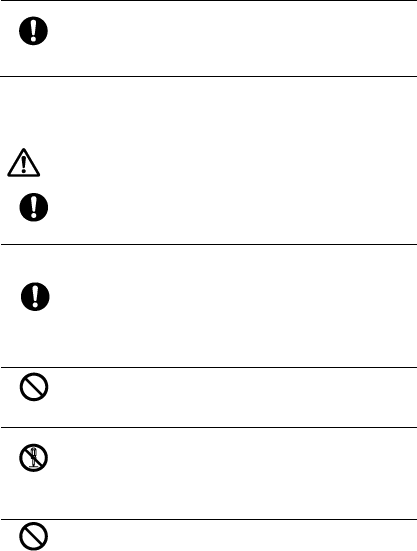
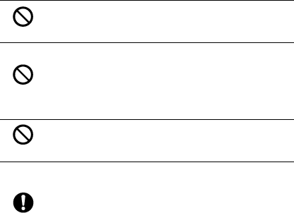
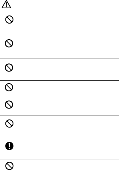
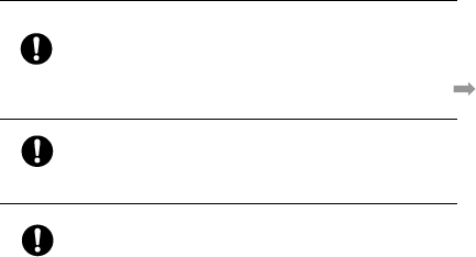
Explanation of the figure sign
To show the
prohibition
contents.
To show the
contents no
disassembly.
To show the
imposition
contents.
Before use
●Our company accept no responsibility for any damage resulting from
user not following the description of this manual.
●Our company accept no responsibility for any damage resulting from
earthquake, fire disaster other than our company responsibility,
third party action, other accident, intent, negligence or incorrect use of
customer, use under other abnormal conditions.
●Our company accept no responsibility for any incidental damage
(change, disappearance of memory contents,
loss of business profit, interruption of business, etc.) resulting from use
or disable of the product.
●Our company accept no responsibility for any damage resulting from
incorrect performance of
the combination of the connected equipment or software our company
have no involvement in.
●Our company accept no responsibility for any incidental damage
resulting from any breakdown,
accident of vehicle or in-vehicle article by the installation of this product.
8
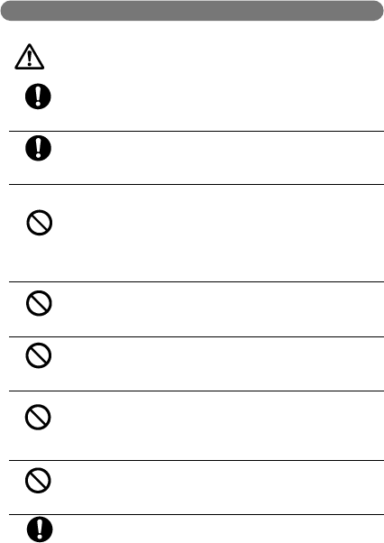
About the product
Do read the following danger items
and use definitely.
imposition
Do not use, storage this product beyond the contents
of this manual.
imposition
Please do use the dedicated peripheral equipment. It
causes heat, ignition, explosion or breakdown.
Prohibition
Do not use, storage or leave at the place which may
become high temperature (beside the fire, beside the
heater, the place receive the direct sun, etc.) or the
place where flammable gas occurs. It causes ignition,
explosion, breakdown or fire. And, part of case may
become hot and make burn.
Prohibition
Do not put it into microwave oven or high temperature
container. It causes ignition, explosion, breakdown or
fire.
Prohibition
Do not put it into fire or heat it up. It causes ignition,
explosion or fire.
Prohibition
Do not shot-circuit the connect terminal. And, do not
insert or touch the conductive materials (metallic
piece, pencil lead, etc.) to the connect terminal. It
causes fire or breakdown.
Prohibition
Do not cover or wrap with cloth or futon during use.
It causes ignition, fire or burn.
Do not install or remove the product during vehicle
running. Please remove the product after stopping the
Dangerous
9
imposition
vehicle in the safe place where parking is not
prohibited, and turning off the ignition (start) key,
then confirming the product stopped.
imposition
Please install the product according to the manual
definitely not affecting the driving, if the product
comes off and drops during driving. It may cause
traffic accident if not installed definitely.
Do read the following warning items
and use definitely.
imposition
Do not drop, throw, trample, or compress to do give
strong shock and load. It causes heat, fire, explosion
or breakdown. In this case, it is out of guarantee.
imposition
Precaution to use near the medical device
To keep this product 15cm more away from the
applied part and use if implanted cardiac pacemaker
or implantable cardiac defibrillator planted. The work
of implanted cardiac pacemaker or implantable
cardiac defibrillator may be affected by the electric
wave.
Prohibition
Do not use the product in the area where the use of
wireless device is prohibited (airport site or hospital
site etc.)
Disassemble
prohibition
Do not change the electrical, mechanical
characteristic (remodel) and use, since it is in
violation of the law. And, it causes breakdown, fire,
shock or injure.
To repair or check, please contact dealer.
The product is not waterproof. Do not pour liquid
such as water. And, do not use at the place where get
Waring
10
Prohibition
water directly or under moist place, or do not use
with the wet hand. It causes breakdown by shock,
electronic circuit short or corrosion. (Be especially
careful to us in rain, snow, or at seashore, waterside)
Please remove the product from the vehicle
immediately if the product gets liquid. The
breakdown due to water wet or humidity is out of
guarantee, and could not repair.
Prohibition
Do not insert metallic materials into device (terminal
part or access cover part). It causes heat,
ignition, shock or breakdown.
Prohibition
Please keep the product away from high accuracy
electric device. It may affect the electric device.
(Samples may be affected: pacemaker, hearing aid,
other medical electric device, etc. If use medical
electric device, please contact device manufacture or
dealer to confirm if there is any effect.)
Prohibition
Do not hurt, rework, twist, drag or put heavy thing
on the cable. And do not use the damaged cable.
It causes shock, short, fire.
imposition
When you install the product, since the product
stands out from the OBDII connector of vehicle,
please confirm the following items.
・Do not lead to poor drive performance of
accelerator or brake.
・No interference to wiring or parts of vehicle.
・If there is cover to vehicle OBDII connector, the
cover may not close when installed the product.
11
Do read the following precautions and
use definitely.
Prohibition
Do not use the product with opening the access cover.
It may cause breakdown because of U-SIM card coming
off and data disappear, dust and substances, water,
humidity enter into the product.
Prohibition
Do not storage at the place where gets the direct rays
of sun, the place becomes high temperature, the
place where becomes extremely low temperature,
the place with humidity and dust. It may cause
deformation or breakdown.
Prohibition
Do not leave the product to the place severe
temperature change (near the air conditioner or
heater). Dew condensation is generated inside and it
causes electric shock, fire, malfunction, or breakdown.
Prohibition
Do not leave the product in nearby infant. It may cause
injuries.
Prohibition
Do not use the product at the humid place. It is out of
guarantee once it’s found that the breakdown is due to
the water or humidity, it could not repair.
Prohibition
Do not use the product and remove it from the vehicle
if abnormality happens such as smoke appears, smell,
unusual sound appear. And do not use the product if it
gets wet with water, drop or damaged.
imposition
Do not use the product and contact dealer if the
electrical component or function of vehicle doesn’t
work normal after installed the product. It may cause
breakdown by continue using the product.
Do not touch the main body or cable for a long period
of time. It may cause low temperature burn.
Caution
12
Prohibition
imposition
If fell any abnormality to skin, please stop using
promptly and consult with dermatologist. Base on the
constitution or physical condition of user, it may cause
itching, rash or eczema.
(「about employed materials and surface processing」
P. 16)
imposition
The product is for normal vehicle. Do not use the
product to the ECU deployment vehicle which
remodeling carried on. It may show abnormal value
or cause breakdown.
imposition
Use the product near human body, please keep away
more than 1.0cm from the body. The product is
confirmed that meet the country technical standard of
human body absorption of electric ware, and the
international guideline of wave protection.
13
●About U-SIM card, please refer to(”about U-SIM card” P. 20)
About U-SIM card
Do read the following warning items
and use definitely.
imposition
Do not leave the product in nearby infant. It may cause
injuries.
It may cause mistakenly eat, swallow or injury.
Do read the following precautions and
use definitely.
Prohibition
Do not add unreasonable force to U-SIM card.
It may cause damage.
Prohibition
Do not add force more than necessary to the U-SIM
card when remove it. It may cause the damage of U-
SIM card or the product, or cause injure to hand or
figure.
Prohibition
Do not resolve or remodel the U-SIM card.
It may cause data disappear or breakdown.
Prohibition
Do not cause injure of IC part. And do not let it short-
circuit. It may cause breakdown.
注意
Warning
警告
Caution
Notice

14
Request in handling
About the product
●Take care of the static electricity when handling the product.
●The product could not be used together with the device which use
vehicle OBDII connector.
●Do not use the product near the device which electromagnetic wave
produces such as cell-phone. Please keep away and use since these
may affect each other.
●Do not remove the indication label.
●The OBDII connector may be used for inspection or maintenance of
vehicle. Do remove the product for inspection or maintenance.
●The battery may go flat when not use in a long time, please remove
the vehicle OBDII connector.
●Do not push hard or pry the Micro USB connector of the product.
●Storage the product at the place with few dust and few moisture. Dust
or moisture may cause breakdown.
●If the product becomes dirty or water-drop adhered, please blot with
dry soft cloth.
●The use of chemicals such as alcohol, benzine, thinner, or wipe may
damage the surface of the product. Please do not use. And, do not wash
in water.
●The LED of the product continues lighting after off the ignition (start)
key OFF, it’s not abnormal. The LED turns off after a short time.
●The product is not covering all the vehicle models. It may not work
based on the vehicle used.
●The product is not to guarantee data acquire from vehicle used.
15
●The information acquired by the product is different based on the
vehicle.
●Special-edition vehicle or vehicle with extra equipment may not work
or could not acquire the vehicle information.
●The product may not work or could not acquire the vehicle information
due to the effect of vehicle age type gap or individual difference
(including miner change, vehicle specification change etc. )
●The product is a device monitoring engine ECU control information.
Therefore, the product may cause error with the vehicle indicator.
●The product adapt to Japan Radio Act. Do not use the product out of
the country since it may go against the law.
●The product may revise software without notice for product
improvement.
●The available vehicle type for the product will updated as needed.
●The product may become hot during use, but is not breakdown.
16
About support vehicle
●The product only can be used to the vehicle which equipped the OBDII
connector to do defect diagnosis communication by K-LINE or CAN.
●The product may not work or could not acquire the vehicle information
due to the effect of vehicle age type gap or individual difference
(including miner change, vehicle specification change etc. )
●Please do not install and use the product if the electric component of
vehicle or function does not work after installed the product.
●The product could not connect to the communication line and acquire
the data tailored to the vehicle used in the state of default status.
Please confirm the vehicle information in advance and do setting to the
product.
About communication state
●the product supports W-CDMA method.
●The product cannot be used in the place where the electronic wave
does not reach such as in tunnel, underground, or in a building, and
having weak electric wave or out of radio area.
About use materials and surface processing
Location
Use materials
Surface processing
Case
PC+ABS
none
Open/Close cover
PC+ABS/Elastomer
none
LED
PC
none
Function button
Elastomer
none
OBDⅡconnector
PBT
none
OBD Ⅱconnector
plate
Stainless
none
OBD Ⅱ connector
terminal
Copper
Tinning
Screw
Carbon Steel
Black trivalent
chromate
Label
PET
none

17
Contents
Read me ................................................................................... 4
Decline ..................................................................................... 4
Checking the suppled items ..................................................... 5
Precautions .............................................................................. 6
Please read carefully for your safety use .................................... 6
About the product .................................................................... 8
About U-SIM card .................................................................. 13
Request in handling ............................................................... 14
About the product .................................................................. 14
About support vehicle ............................................................ 16
About communication state .................................................... 16
About use materials and surface processing ............................. 16
Contents ................................................................................ 17
1 Before using ............................................................................. 18
Part names ............................................................................ 18
About LED .............................................................................. 19
About USIM card .................................................................... 20
Installation to vehicles ................................................................ 22
Installation preparation ......................................................... 22
Attach the safety strap to the product...................................... 23
Attachment direction of the product ........................................ 24
Connection to vehicles ........................................................... 25
OBD II connector position of vehicles ....................................... 25
Not use socket extension cable ............................................... 26
Use socket extension cable ..................................................... 27
Installation of the product ..................................................... 28
Install the product to vehicle ................................................... 28
Fix socket extension cable ...................................................... 30
Attach the safety strap ........................................................... 31
3 Default setting ......................................................................... 32
Vehicle information automatic setting .................................... 32
Default setting of acceleration sensor .................................... 33
4 Operation ................................................................................. 34
5 Appendix .................................................................................. 35
Troubleshooting ..................................................................... 35
Specifications ......................................................................... 36
18
1 Before using
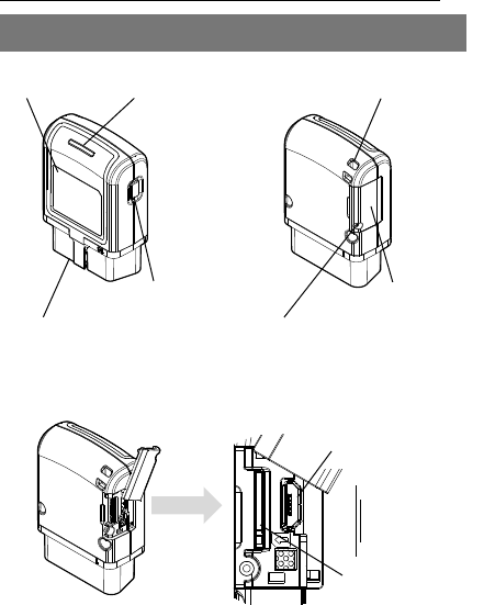
Part names
Maintenance connector
U-SIM card slot
LED
Strap hole
Label
OBDⅡ connector
Function button
Open/close cover
Screw of open/close cover
Enlarged view of open/close
cover

19
About LED
Notice the power state of the product, electric wave status, and other states by
lighting and blinking pattern of LED.
LED state
Device state
Lights out
Power OFF
Green (lighting)
Power ON(in service area)
First connection to vehicles(in service area)
Green (blinking)
Service area judging
Default setting of acceleration sensor
Orange (lighting)
Power ON(out of service area)
First connection to vehicles (out of service area)
Orange (blinking)
Software updating
Downloading of setting information
Red (lighting)
W-CDMA certification error
SSL certification error
Server certification error
Other Server error
Red (blinking)
Possibility of failure
APN connection error
U-SIM reading error
(including the reading error due to PIN lock)
Green/Red (blinking)
Default setting failure of acceleration sensor
Orange/Red
(blinking)
Software update failure
Server communication timeout
Download failure of setting information
20
About USIM card
U-SIM card is an IC card on which the information such as a telephone number
of user is recorded.
When performing data communications using the product, it is necessary to insert
U-SIM card to the product first.
Please insert U-SIM card when the product power OFF (not connected to
vehicles).
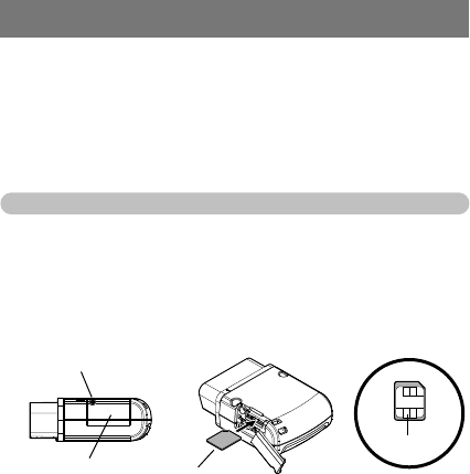
Insertion of U-SIM card
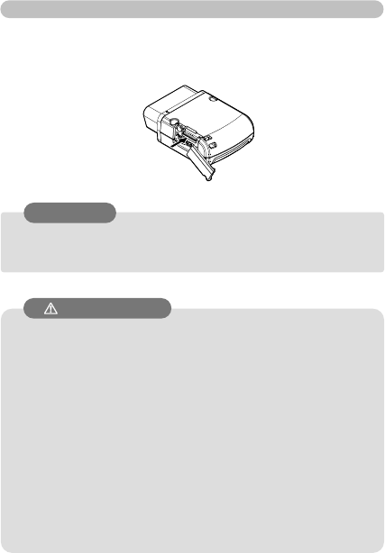
Please loosen the open/close cover fixe screw, open the cover, make IC
downward and insert U-SIM card into card slot, then push until clicking noise
sounds.
Please check that it has inserted normally, then close the open/close cover, and
tighten the fix screw of open/close cover.
IC part
Screw of open/close cover
Open/close cover
U-SIM card
21
● It may cause U-SIM card broken if insert or remove U-SIM card
forcedly.
● The data in U-SIM card may disappear if remove U-SIM card
when power ON.
● Please keep the product power OFF (not connected to vehicles)
and then open or close the cover.
If the open/close cover is open, U-SIM card may remove by
mistake.
● Do not touch IC part of U-SIM card directly or damage it.
The IC part contaminated may cause loose connection or not
communicate.
● Do not miss the U-SIM card if removed it.
● Do not stick seal to U-SIM card.
It may be damaged.
- The product cannot perform data communication without inserting U-
SIM card to card slot.
- If it is going to attach U-SIM card by force or tries to remove, there is a
possibility of damaging U-SIM card.
- If U-SIM card is removed with a power supply turned on, the data in U-
SIM card may disappear.
- When you open or shut an opening-and-closing cover, please carry out
in the state (state which has not been connected to vehicles) where this
product is turned off.
If the opening-and-closing cover is open, there is a possibility of
removing U-SIM card accidentally.
- Please touch the IC section of U-SIM card or do not damage.
When the IC section is dirty, contact worsens and communication
becomes impossible.
- When you remove U-SIM card, please be careful not to lose.
- Please do not use it, sticking a seal etc. on U-SIM card. There is a
possibility of damaging.
Extraction of U-SIM card
Please loosen the open/close cover fixe screw, open the cover, and push U-SIM
card until clicking noise sounds.
U-SIM card will protrude once leave finger, then U-SIM card can be removed.
Notice
Cautions

22
●Do not install or remove the product during vehicle running.
Please remove the product after stopping the vehicle in the safe
place, and turning off the ignition (start) key, then confirm the
product stop and remove it.
●Before the installation work of the product, do touch the metal
part of vehicle to eliminate static electricity from body.
● Do not use items other than supplied items when installation the
product.
●Install the product to vehicle surely with the safety strap.
●In the vehicles using glasses which go through electric wave
hardly, such as metal glass (heat rays reflection glass) etc., the
product may not work because of not receiving GPS electric wave
in vehicles.
●The product may not receive GPS if installed in center console. In
that case, install the product to where can receive PGS by using
socket extension cable.
●The acceleration may not acquire normally if installation the
product to OBD II connector directly. In that case, install the
product with correct direction by using socket extension cable.
●The installation position may lead to poor driver performance if
install the product to OBD II connector directly. In that case, install
the product to the position not lead to poor driver performance
using socket extension cable.
● Use the product near human body, please keep away more than
1.0cm from the body. The product is confirmed that meet the
country technical standard of human body absorption of electric
ware, and the international guideline of wave protection.
Installation to vehicles
Installation preparation
Cautions
23
●Do the reverse procedure of attachment to remove the safety
strap.
Attach the safety strap to the product
Please attach the safety strap to prevent the product failure due to drop,
or the accident due to the product drop during using vehicles.
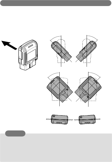
Assemble the safety strap.
Pass safety strap through the hole of convex base, and pass the other
end of strap through the ring of strap end.
Attach the product to the safety strap
Pass the safety strap through the strap hole of the product, and then pass
the convex base through the ring of strap end.
Request
24
●To attach the product with supplied double-stick fix tape to
where avoid direct rays of sun as possible, not affect driver
performance, and avoid air conditioner outlet
●Using the safety strap and supplied fix tape to stabilize the
socket extension cable not hang down or drop.
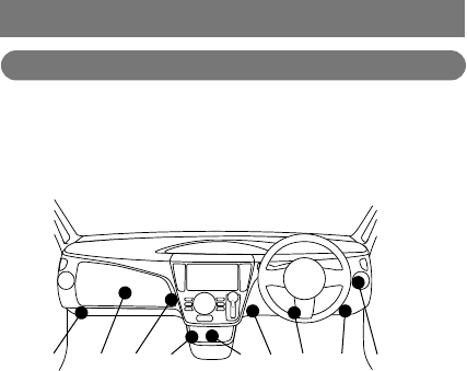
Attachment direction of the product
Please attach the product in the direction within the range of the chart
below to acquire acceleration information definitely.
It may not do default setting of acceleration sensor correctly or not
acquire acceleration information definitely if exceed such range.
45°
45°
5°
5°
45°
45°
Request
Vehicle direction
25
Connection to vehicles
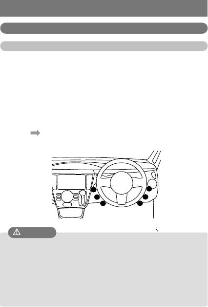
OBD II connector position of vehicles
The OBD II connector of vehicles is under the dash panel or at back of it.
The connector position may vary according to vehicle models and age
types.
Please confirm the setting position as below image.
➀ In the steering right panel
② Lower right of driver seat step
③ Center of driver seat step
④ Lower left of driver seat step
⑤ Center console
⑥ Back of center console
⑦ Back of front passenger seat center console
⑧ Back of glove compartment
⑨ On the kick panel of front passenger seat
It may be covered by cap or panel cover according to the vehicle type.
①
②
③
④
⑤
⑥
⑦
⑧
⑨
26
●To connect the product to OBD II connector of vehicles directly, it
may lead to poor drive performance according to the position. In
that case, please use socket extension cable.
●The default setting of acceleration sensor may not carry out
definitely or the acceleration information may not acquire definitely
according to the installation position of the Product. In that case,
please use socket extension cable.
●If the installation position of the product gets direct rays of sun
or the wind of air conditioner directly, please use socket extension
cable.
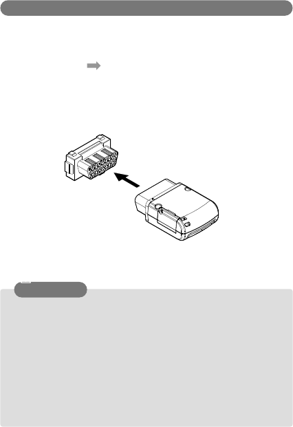
Not use socket extension cable
Connect the OBD II connector of the product to OBD II connector of
vehicles.
The position of vehicles OBD II connector refers to “OBD II connector
position of vehicles” ( P.25)
Moreover, do connect the product after turning off the ignition (start) key.
The product starts work once connected.
Vehicle OBDⅡ connector
Caution
27
●Do the reverse procedure of attachment to remove the product.
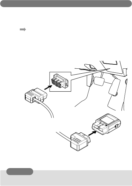
Use socket extension cable
Connect the OBD II connector of the product and OBD II connector of
vehicles through socket extension cable.
Vehicles OBD II connector position refer to “OBD II connector position of
vehicles” ( P.25)
Do connect the product after turning off the ignition (start) key. The
product starts work once connected.
Connector position is an example.
Vehicle OBDⅡ connector
Socket extension cable
(Sample)
Request
The product
28
●Never attach the product to where the air-bag works or other
security parts related. It may cause serious accident.
●The position to attach the product please avoid where gets
direct rays of sun, lead to poor driver performance, and the air-
conditioner outlet.
●It is necessary to fix the cable if use socket extension cable.
Decide the product installation position in consideration of the
fixation of socket extension cable.
Installation of the product
Install the product to vehicle
The product installation position
The production available position may vary according to the vehicle model
or age types.
And, please choose the position not lead to poor drive performance to
install the product.
Moreover, the default setting of acceleration sensor may not carry out
definitely or the acceleration information
may not acquire definitely according to the installation position of the
Product.
The acceleration information refers to “Installation direction of the
product” ( P.24).
If the position information cannot acquire definitely or any other question,
please contact the dealer.
⑩ In the steering right panel
⑪ Lower right of driver seat step
⑫ Center of driver seat step
⑬ Lower left of driver seat step
⑭ Center console
⑮ Back of center console
⑯ Back of front passenger seat
center console
① In the steering right panel
② Lower right of driver seat step
③ Center of driver seat step
④ Lower left of driver seat step
⑤ Center console
⑥ Back of center console
⑦ Back of front passenger seat
center console
⑧ Back of glove compartment
⑨ On the kick panel of front
passenger seat
Installation position(sample)
Caution
29
●Please stick tape after removing oil or dust of the sticky side of
device fixation double-stick tape.
●When pasting the device fixation double-stick tape, please press
the device strongly and clamp surely.
In addition, it takes about 1 day for adhesive strength of tape
function well, please do not add power to the product during such
period.
●Do not use screws or nails to fix the product. It may cause the
product damaged.
●Device fixation double-stick tape only use for attaching socket
extension cable.
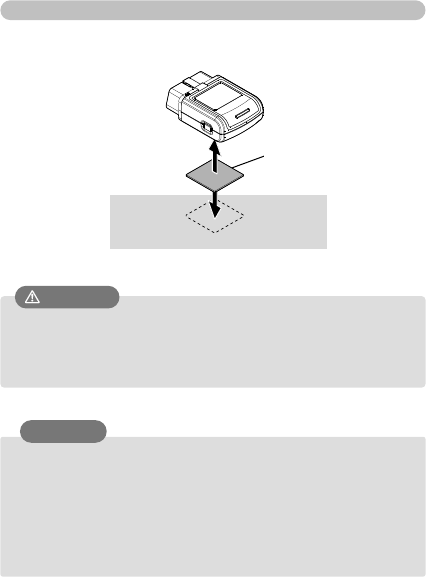
Installation of the product
Fix the product to vehicles using double-stick tape.
Vehicle
Request
Caution
Double-stick tape
for device fixation
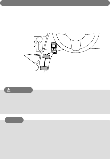
30
●Please stick tape after removing oil or dust of the sticky side of
device fixation double-stick tape.
●When pasting the device fixation double-stick tape, please press
the device strongly and clamp surely.
In addition, it takes about 1 day for adhesive strength of tape
function well, please do not add power to the product during such
period.
●Never attach the product to where the air-bag works or other
security parts related. It may cause serious accident.
●Do not use screws or nails to fix the product. It may cause the
product damaged.
Fix socket extension cable
It’s necessary to fix the cable to vehicles not lead to poor driver
performance when using socket extension cable.
Please fix the socket extension cable to vehicles using the supplied
fixation tape.
Request
Installation sample
Caution
Fixation tape
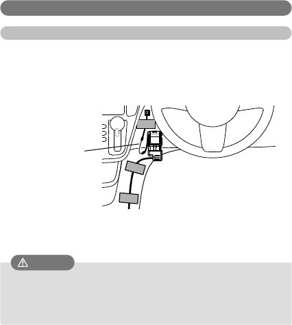
31
●Never attach the product to where the air-bag works or other
security parts related. It may cause serious accident.
●Do not use screws or nails to fix the product. It may cause the
product damaged.
Attach the safety strap
Attach the safety strap
Please attach the safety strap to the position not lead to poor driver
performance with the double-stick tape on the back of convex base.
Fix the string of safety strap to vehicle interior with supplied fixation tape.
Cation
Attachment sample
Safety strap

32
●The power of the product will turn on and start setting
information download automatically even if the engine is stopped
when first connection.
●Please confirm the LED indication change while setting
information downloading.
●After LED lighting, blinking, the power of the product will turn
off automatically.
3 Default setting
It is necessary to configure the automatic setting of vehicle information
and default setting of acceleration sensor before the product operation
start.
Vehicle information automatic setting
The LED lighting green and download of setting information start
automatically once the product connected to vehicle first time.
While setting information downloading, LED blinking in orange. The
power of the product becomes OFF (LED light off) after download
complete.
If automatic setting is not completed due to electric ware environment,
LED lighting in green or orange continuously (LED not light off) and red
lighting or blinking in orange and red.
In such case, please move to good electronic wave environment (※)
and continue pushing function button over 2 sec and carry out re-setting.
※LED lighting in green when in service area and in orange when out of
service area.
Notice

33
●Please perform default setting at the place that not disturb
other vehicles.
●The default setting may not be completely definitely if do
setting at grade road such as slope and big shaking road such as
on the bridge. In such case, it is necessary to perform default
setting again.
●Please make sure perform procedure 2 and procedure 3 in the
state that stopped vehicle.
●During procedure 3, please do not perform the opening or
closing of doors and windows of the vehicle. The default setting
may not be completed definitely.
●The default setting may fail if moving the vehicle during default
setting. If fail, LED turns to blinking green and red, and then
returns to the indication of power ON.
●The power of the product becomes ON automatically when start
engine of vehicle.
Default setting of acceleration sensor
It is necessary to carry out default setting of acceleration sensor to
acquire the acceleration information definitely.
Please confirm the LED indication change while doing default setting.
Default setting procedure of acceleration sensor
1. Stop in a safe place.
2. Start engine of vehicle, and power of the product ON.
3. Press the function button about 2 sec and then release.
Please start after LED lighting green. LED repeats blinking in green about
15 sec.
LED returns to the indication of power ON and default setting complete.
Notice

34
●The switch which changes power ON/OFF to the product is not
attached
●LED of the product continues lighting after ignition (start) key
OFF, but it is not abnormal. The LED turns off in a few minutes.
4 Operation
Turn on the power
The power of the product becomes ON automatically when start engine
of vehicle.
LED becomes blinking green several seconds later, and then light on
green or orange.
※LED shows the electric ware status.
Green lighting:in service area
Orange lighting:out of service area
Turn off the power
LED of the product turns off and power becomes OFF automatically after
ignition (start) key OFF.
Notice

35
5 Appendix
Troubleshooting
Please confirm the following items first if the product does not work
normally.
And please contact the dealer if the product does not work normally after
confirmation
Symptom
Confirmation contents
LED of the product
does not light even if
connected to vehicle.
●The product may not be connected
definitely. Please connect the product or
socket extension cable (sample) with
surety once again.
●Please use the supplied socket extension
cable (sample). The general-purpose
extension cable may be unusable.
●The default setting starts automatically
and LED lighting when connected the
product to vehicle first time, and turns off
once setting completed.
●Do you start engine of vehicle?
●Is the vehicle intended of the product?
LED blinking red
●The product may be breakdown, please
contact the dealer.
●Please confirm whether U-SIM card is
inserted definitely or not.
●The setting of U-SIM card may be not
correct. Please contact the dealer.
LED doesn’t become
green
●Do you start engineer of the vehicle?
●Please move the vehicle into service
area.
LED blinking in orange
and red
●It may be server failure. Please contact
dealer if doesn’t resume for a while.
36
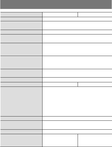
Specifications
Product Name
GX410NC
GX420NC
Interface
OBDⅡ connector
Power voltage
10.8~15.1V(12V vehicle)
21.0~30.0V(24V vehicle)
Consumption Current
310mA less
Socket extension
cable(Sample)
About 0.3m
System requirements
Temperature -10℃~55℃
(No condensation)※
Humidity 10%~75%( No condensation)
Storage condition
Temperature -20℃~85℃
(No condensation)
Humidity 5%~85%( No condensation)
Dimension
63(H)×45(W)×22(D) mm
(not include projection and accessories)
Weight
About 55g (not include accessories)
Frequency
2100MHz/800MHz
2100MHz/900MHz
Communication
speed
Download MAX 14.4Mbps
Upload MAX 5.76Mbps
(It is the best effect, the communication
speed and quality may change based on
the situation and states of the moment.
And the communication speed may limit
by the contract detail of the U-SIM card.)
GPS
Stand-alone
Communication
protocol
TCP/IP/UDP/PPP/SSL
Sensor
Three-axis acceleration sensor
Specific absorption
rate SAR(Maximum
value)
0.655 W/kg
0.700 W/kg
※The temperature restrictions function works and the communication
may not continue by the usage environment.
Communication does not reopen if the environment temperature
does not decrease once temperature restrictions start.

37
Compliance Statements:
This device complies with Part 15 of the FCC Rules and with RSS-210 of Industry Canada.
Operation is subject to the following two conditions:
(1) this device may not cause harmful interference, and
(2) this device must accept any interference received, including interference that may cause
undesired operation.
Ce dispositif est déclaré conforme à la Partie 15 de la Réglementation FCC et à la norme RSS-
210 d’Industrie Canada. Son fonctionnement est soumis aux deux conditions suivantes:
(1) cet appareil ne doit pas causer d’interférences nuisibles, et
(2) cet appareil doit accepter les interférences reçues, y compris celles
susceptibles de causer un fonctionnement indésirable.
Modifications not expressly approved by NCXX Inc. could void the user’s authority to operate the
equipment.
This equipment has been tested and found to comply with the limits for a Class B digital device,
pursuant to Part 15 of the FCC Rules. These limits are designed to provide reasonable protection
against harmful interference in a residential installation. This equipment generates, users and can
radiate radio frequency energy and, if not installed and used in accordance with the instructions,
may cause harmful interference to radio communications. However, there is no guarantee that
interference will not occur in a particular installation. If this equipment does cause harmful
interference to radio or television reception, which can be determined by turning the equipment
off and on, the user is encouraged to try to correct the interference by one or more of the following
measures:
- Reorient or relocate the receiving antenna.
- Increase the separation between the equipment and receiver.
- Connect the equipment into an outlet on a circuit different from that to which the receiver is
connected.
- Consult the dealer or an experienced radio/TV technician for help.
Radiofrequency radiation exposure Information:
This device has been tested and meets the FCC RF exposure guidelines when installed at least
10mm from the body.