ND Information Technology System PS4000-1103 POS Terminal User Manual
Shanghai SAND Information Technology System Co., Ltd POS Terminal
User Manual
PS4000 User Manual
Version Record
Version Date No. Compiler/ by Checker by/
Approver by
V01 2010-6-1 Fan Chungang
1
PS4000 User Manual ........................................................................................................................1
1. Introduction.......................................................................................................................3
2. Technical Parameter..............................................................................................................3
3. Outside View and Packaging.................................................................................................5
4.Function Interface ..................................................................................................................6
4.1 Power Input...............................................................................................................6
4.2 Keyboard...................................................................................................................6
4.3 LCD & Touch Panel .................................................................................................7
4.4 IC Card ......................................................................................................................7
4.5 SAM Card..................................................................................................................7
4.6 Magnetic Card..........................................................................................................8
4.7 Buzzer .......................................................................................................................8
4.8 Serial Port............................................................................................................8
4.9 USB............................................................................................................................9
4.10 T-Flash ....................................................................................................................9
4.11 Indicator...................................................................................................................9
4.12 Printer.................................................................................................................10
4.13 Battery...................................................................................................................10
4.14 RTC........................................................................................................................11
4.15 Power Switch........................................................................................................11
4.16 GPRS ....................................................................................................................11
5. Installation and adjustment .................................................................................................12
5.1 Environmental Requirements...............................................................................12
5.2 Power Requirements.............................................................................................12
6. Repairs and maintenance.....................................................................................................12
6.1 Maintenance matters.............................................................................................12
6.2 Maintenance matters.............................................................................................12
7. System components.............................................................................................................13
8. Complete set........................................................................................................................13
9. Safety precautions...............................................................................................................13
10. SAR Info .....................................................................................................................13
2

1. Introduction
PS4000 is a handhold POS terminal. It supports bank card, Unionpay card, and
electrical currency trade of foreign currency card. It support document print. Mobile
charges can be accomplished by communication of GPRS, such as door to door utility
fees collecting, taxi fees paying and traffic police issuing fine to drivers, especially
applicable to home-delivery center, passenger ticket center, tax authorities, express
company, mobile sales point, restaurant, take-out service, and e-commercial
transaction, etc.
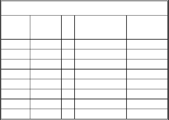
2. Technical Parameter
Processor ARM920 CPU (66~266MHz)
64M NandFlash
64M SDRAM
Memory
TF card interface(support expansion to 4G)
Display 3.5" 240×320 TFT Display screen
Indicator 4 Led indicators, power, charge, Tx, Rx
Tx、Rx programmable
Charge indicator, available on power off, only indicating
battery charging
keyboard 11 numeral/letter keys, 4 direction keys, 5 function keys.
Pinter Thermal printer, 58mm(w)×40mm paper roll, print speed
changeable
Magnetic track 1/2/3 magnetic track
IC card ISO7816 standard(T=0、T=1)
SAM card 3
USB1.1 Host × 1 support U disk, USB keyboard, mouse,
etc.
USB(2 choices)
Communication
interface
Wireless 2G;
GPRS
3

RTC RTC clock, variable1~2s/Day
RTC battery, inbuilt, last for 2 years Battery
Main battery: 7.4V 2000mAH lithium battery
Power input DC 9.0V 4A adapter
OS Linux
SAND SDK for Linux Second time
development Several download type optional, USB、TF card、serial port,
support TMS
Support
multi-applicatio
n
Support about 100 applications
Size 206×88×68.5mm
Weight 542g(bard code module included)
Working
environment
Temperature:0~50 centigrade Humidity:10%~90%;
Storage
environment
Temperature: -20~70°C; Humidity:5%~95%;
Table 2-1
4
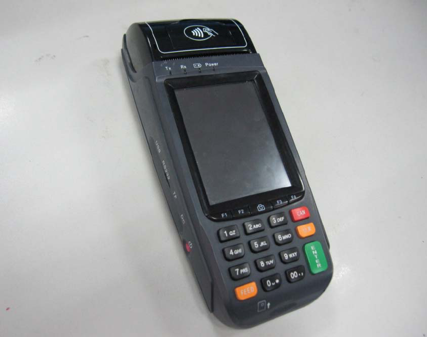
3. Outside View and Packaging
Picture 3-1
5
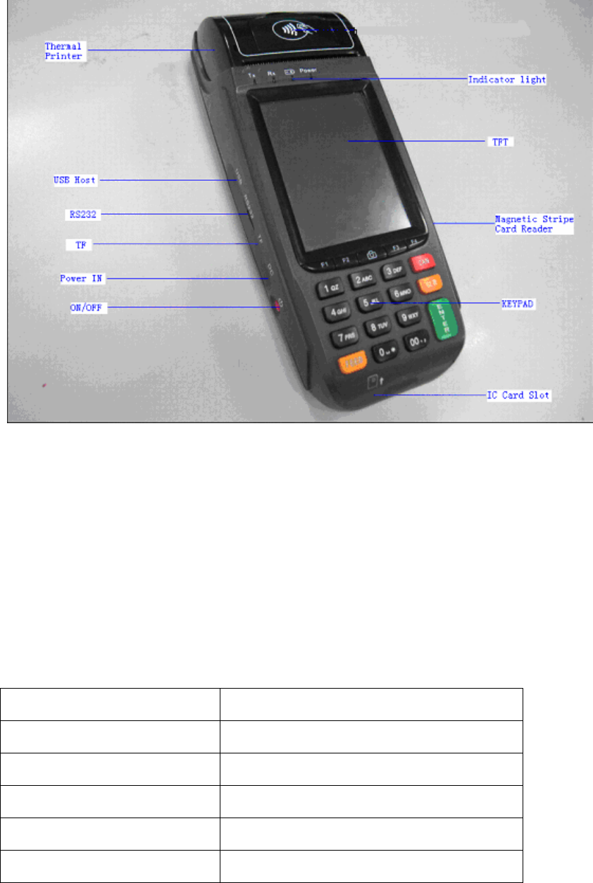
4.Function Interface
Picture 4-1
4.1 Power Input
Input DC, internal positive and outside negative, voltage scope 9-12V
PS4000 standard power adapter: 9.5V/4A。
4.2 Keyboard
PS4000 have 20 keys, 10 numeral keys, 10 numeral function keys.
Key Introduction
0-9 Numeral keys
Cancel(CAN) Cancel
Clear(CLR) Clear or move back
Enter(Enter) Enter
Paper feed(FEED) Paper feed
6

00 double ‘0’ keys
F1-F4 Multi-function key, normally for direction
or page up or down
Camera Photo and scanner
Table 4-1
The terminal will give out beep sound if the key press is effect. The keyboard
backlight also lights on and will light off 15 seconds after no key press is detected
(time can be defined).
Attention: Key pressing for long time will be treated as one time pressing event
not several times.
4.3 LCD & Touch Panel
PS4000 LCD is a 240×320 3.5' TFT screen with 24Bit RGB. The touch panel is
optional.
4.4 IC Card
IC card slot is below the keyboard of the pos terminal. Insert card to the slot with
the contact side upward.
4.5 SAM Card
There are 3 SAM cards under the battery at back of the PS4000 terminal.
SAM1,2,3 from the top down.
7
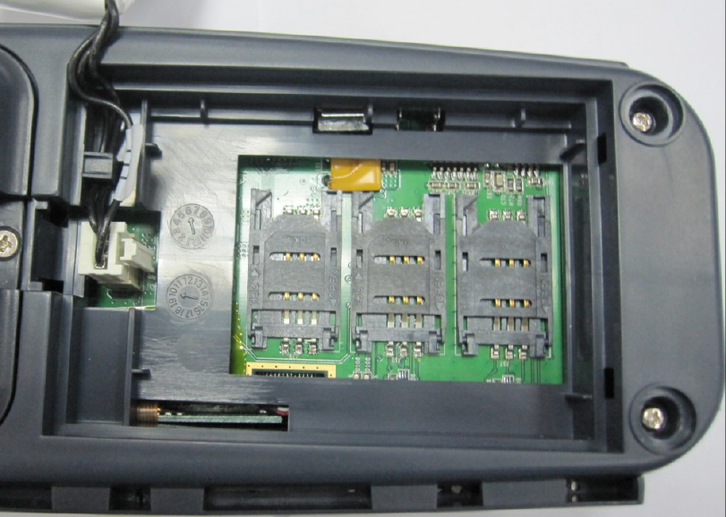
Picture 4-2
4.6 Magnetic Card
The magnetic card reader is on one side of the terminal. Swipe the card with the
magnetic strip inby in right or reverse direction.
4.7 Buzzer
There is an inbuilt buzzer in the PS4000 terminal. It normally buzzes when key is
pressed or to alert.
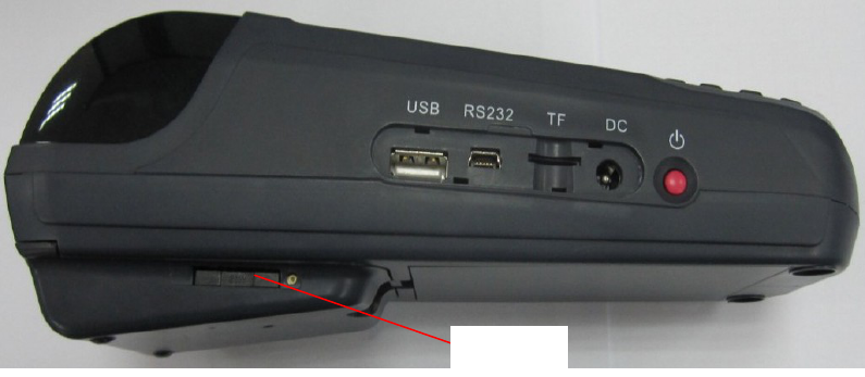
4.8 Serial Port
There is a serial port at the left side of PS4000 terminal. It is standard RS232
serial port, while its structural interface is Mini-USB interface. The terminal can be
connected to PC or other device by a special serial line made by SAND.
Attention: Do not insert USB connecting line to this interface by mistake.
8

4.9 USB
The USB port is at one side of the POS terminal near the serial port. This USB
Host 1.1 port supports U disk, USB keyboard and mouse, etc.
Attention: Maximum USB power supply is 500mA
4.10 T-Flash
T-Flash card slot is at one side of the pos terminal. It supports standard T-Flash
card.
4.11 Indicator
There are 4 lights at front of the TFT LCD, from right to left they are for power,
charge, RX, and TX.
Power Power indicator of the system, if
lights on means work of system.
Charge Charge indicator, if lights on
means adapter is inserted and
battery is being charged, lights
off means adaptor is not inserted
or charge finished that the
adapter can be pulled out.
RX GPG8 Communication receiving
indicator
TX GPG1 Communication sending
indicator
Table 4-2
9
4.12 Printer
Picture 4-3
PS4000 printer adapts mini thermal printer with low power consumption. The
paper roller is at front of the terminal with its size is 58mm (W) and 40mm (D).
Please put in the paper roller when use. Lift the small cover in the print paper
cover lightly, open the paper container, put in the paper roller, pull out certain length
of the paper and press it closely to and at middle of the paper cutter, then press the
paper cover tightly and make sure the paper roller stuck in the printer, pull the paper
out certain length to check if is installed correctly. (or select paper feed in the main
menu and make the printer work for a few seconds).
Attention: There is paper lack detection and over heat protection in the printer,
please operation following what the screen tells.
4.13 Battery
Main battery locates at the back of the POS terminal, press the clip to open the
battery container. Please put out the battery if no use for long time.
10
Please recharge the battery with standard power adapter provided by SAND if it
is running down, When battery recharge, if the terminal is power on, the screen will
display charging indicator, if power off, the indicator in the screen will tell if charging
is finished. Power indicator lights means it is charging and lights out means charging
finished or no power adapter inserted.
4.14 RTC
Built-in RTC clock in PS4000, and furnished with proprietary battery which can
work for 2`3 years. Please set the time when first use.
4.15 Power Switch
The power switch is a red button locating in the side edge of the terminal.
Start up by pressing for short time and shut down by pressing for long time(2-3s)
only under abnormal situation. Normal shut down process should use the down
function of the system in case of data lost.
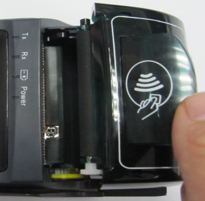
4.16 GPRS
SAM card
Picture 4-4
PS4000 GPRS is inbuilt in the cover in front of the terminal. The SIM card
locates in the side edge of the terminal, it will come out by pressing the yellow button
in the SIM card slot with pinpoint or other pointed object.
Attention: Do not replace the SIM card when power on.
11
5. Installation and adjustment
5.1 Environmental Requirements
The Product requests ventilation, suitable temperature, to avoid high temperature,
humidity, corrosive gases, avoid direct sunlight.
5.2 Power Requirements
Product within the power supply as 9.5V 4A is outside the negative.
Charger must be used in the security area.
6. Repairs and maintenance
6.1 Maintenance matters
After the boot screen machines were not the main show or not power: ① Check
the power adapter is external normal power supply has been inserted in the socket on
the external adapter ②External power adapter is bright ③ the power indicator on
whether the external adapter plug socket closely with the Cash Register ④ the power
switch is good contact, can be repeated several test switch ⑤ Following the above
operation, if the POS machine power indicator on the panel were not the main screen
display or no display shall promptly contact the factory maintenance, do not open the
machine without permission.
6.2 Maintenance matters
Avoid high humidity or sun exposure.
Avoid wet ,corrosive environments, water is strictly prohibited.
Gently, using the drop should be placed on the environment is not easy to use, to
prevent the break.
When the machine looks dirty, soft cloth can be used to prohibit the use of
chemicals reagents.
In the daily cleaning of the product should be used when a soft damp cloth, not
use silk, chemical fiber fabrics easily lead to static electricity.
12
Prohibited demolition at dangerous places, installing the battery pack.
7. System components
PS4000 for portable electrical equipment, no correlation equipment.
8. Complete set
Supporting the use of the following products:
ADP036-094B Power Supply
Thermal paper (57 × 40mm)
9. Safety precautions
Read carefully before using this manual, the proper use of this product. Please
keep this manual to properly check in at any time convenient place.
When using this product should note the following:
Product failure by the manufacturers maintenance, user shall not change the
product mix.
Product installation, use manual and maintenance should also comply with
product instructions.
In the daily cleaning of the product should be used with a soft damp cloth, not use
silk, chemical fiber fabrics easily lead to static electricity.
Product charging must be in safe areas.
10. SAR Info
1. This device complies with Part 15 of the FCC Rules. Operation is subject to the
following two conditions:
(1) This device may not cause harmful interference.
(2) This device must accept any interference received, including interference that may
cause undesired operation.
2. Changes or modifications not expressly approved by the party responsible for
compliance could void the user's authority to operate the equipment.
Designed and manufactured not to exceed the emission limits for exposure to
radiofrequency (RF) energy set by the Federal Communications Commission of the
13
U.S. Government.These limits are part of comprehensive guidelines and establish
permitted levels of RF energy for the general population. The guidelines are based on
standards that were developed by independent scientific organizations through
periodic and thorough evaluation of scientific studies. The standards include a
substantial safety margin designed to assure the safety of all persons,regardless of age
and health. The exposure of measurement known as the Specific Absorption Rate, or
SAR. The SAR limit set by the FCC is 1.6W/kg. transmitting at its highest certified
power level in all Your POS Terminal is a radio transmitter and receiver. It is at the
highest certified power level, the well below the maximum value. This is power levels
so as to use only the power required to reach the network. In general, the closer you
are to a wireless base station antenna, the available for sale to the public, it must be
tested and certified to the FCC that it does not exceed the limit established by the
government adopted requirement for safe exposure. The tests are performed in
positions and locations (e.g., at the ear and worn on the body) as required by the FCC
for each model. The FCC has granted an Equipment Authorization for evaluated as
in compliance with the FCC RF exposure guidelines. SAR information on this model
the Display Grant section of http://www.fcc.gov/ oet/fccid after searching on FCC ID:
XLHPS4000-1103.
14