NDS Surgical Imaging TZM7201 Mini PCI UWB Module User Manual Manual
NDS Surgical Imaging Mini PCI UWB Module Manual
Manual
ZeroWireTM Mini PCI Board
(TZM7201) Manufacturing guide

2
Table of Contents
ZeroWireTM Mini PCI Board (TZM7201) Manufacturing guide 1
Table of Contents 2
Date: 06/24/2008 3
Introduction 3
TZM7201 Mini PCI board 3
Hardware options 3
Antenna options 3
Antenna cabling options 4
Firmware options 4
Typical manufacturing label 4
Installation instructions 5
3
Date: 06/24/2008
Introduction
Tzero’s ZeroWire Mini PCI board (TZM7201) is the next generation platform, which is
based on the TZC7200 chipset. It contains the Tzero ZeroWire TZC7200 (TZR7200Q
RF chip and TZB7200 baseband chip), along with other supporting components such as
single data rate SDRAM memory, filter, RF switch, and antenna. The ZeroWire Mini PCI
board forms a complete UWB wireless system and is capable of operating at all
WiMedia defined PHY rates, ranging from 53.3Mbps to 480Mbps
TZM7201 Mini PCI board
▪ Board size: Type IIIA, 59.7x 50.9mm
▪ R1 – 1mm thickness, 6-layers PCB
Hardware options
Current hardware revision: rev 5.0
Below is the hardware option matrix:
MMCX connector UFL connector
Single RX board x x
Dual RX board x x
Antenna options
Antenna Type
Gain (dBi)
Omron WXA-S1FL, monopole 0
Omron WXA-N1FL, SMD ceramic monople 0
Taiyo Yuden AH 086M555001AE, SMD ceramic monopole 0
4
Antenna cabling options
Cable Type
Insertion loss (dB)
UFL – reverse polarity female SMA 4-inch long, 1.3mm cable -0.6 dB
UFL – reverse polarity female SMA 6-inch long, 1.3mm cable -0.8 dB
MMCX – reverse polarity female SMA 4-inch long, 0.100” cable -0.3 dB
MMCX – reverse polarity female SMA 6-inch long, 0.100” cable -0.5 dB
Firmware options
Below is the firmware option matrix with current versions:
FCC compliant
Calibrate for all TFC
ETSI, Telec compliant
Calibrate for TFC 7 only
Hardware Dual RX Single
RX
Dual RX Single RX
Manufacturing test firmware 1414 1421 1414 1421
RX / Client 4101 3106 Application
firmware
TX / Server 4001 3016
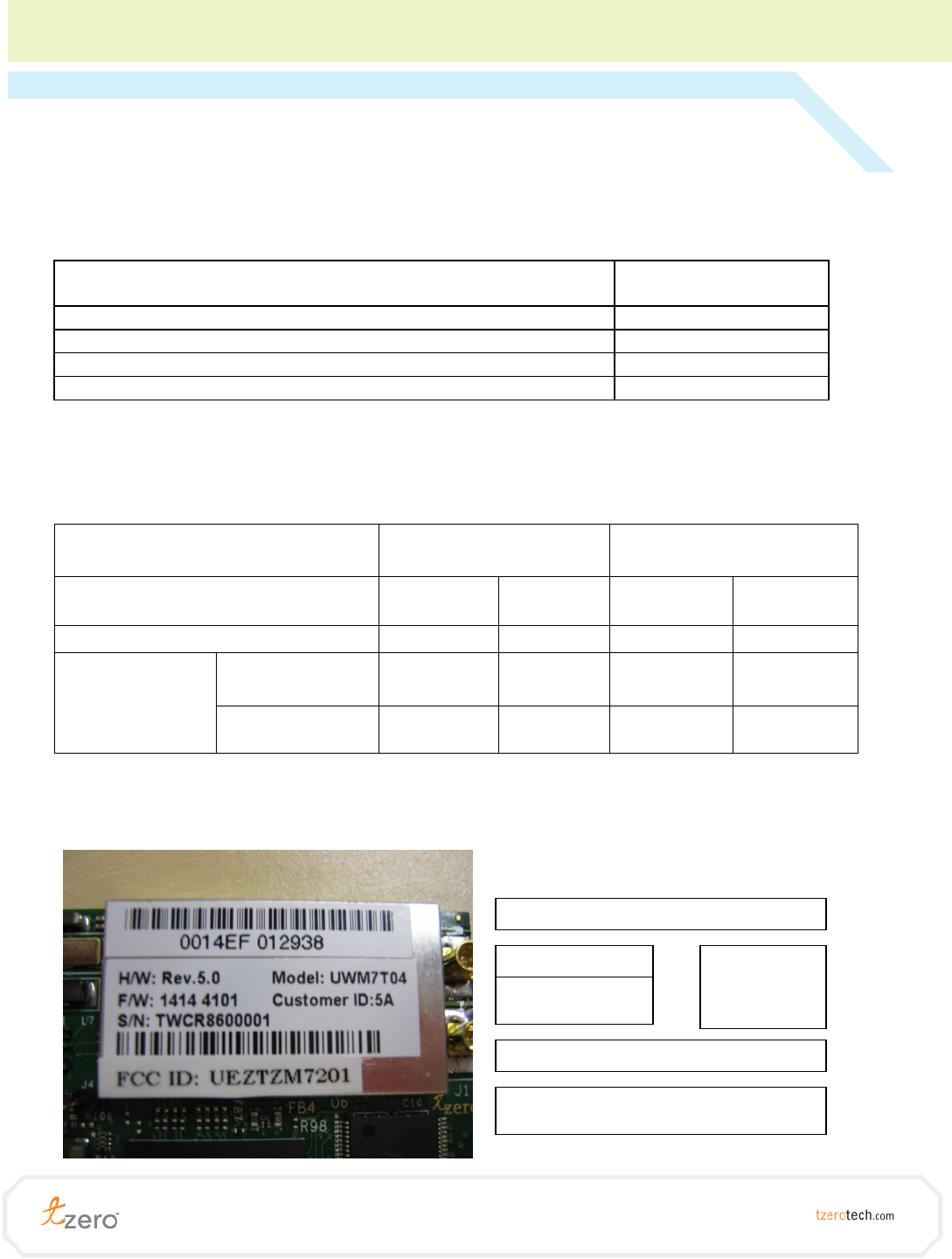
Typical manufacturing label
This typical manufacturing label is applied on the RF shield cover of the miniPCI board
MAC address 0014EFxxxxxx
H/W
r
ev
F/W test app
ODM ID
ODM information
Notify body ID

5
Installation instructions
Note:
To install the miniPCI board:
1. Verify the hardware option to match with the video codec board
a. Single RX miniPCI board for Tx / Server codec board
b. Dual RX miniPCI board for Rx / Client codec board
2. Insert the miniPCI board into the miniPCI socket on the codec board
3. Connect the one or two RF connections depending on the hardware used. See
the antenna options and antenna cabling options for more details
4. Apply the certification label visible on the backside of the final product. For FCC,
the external label must have this “Contains FCC ID: UEZTZM7201” wording plus
the typical FCC warning. Example:
“Contains FCC ID: UEZTZM7201. This device complies with Part 15 of the FCC Rules.
Operation is subject to the following two conditions: (1) This device may not cause
harmful interference, and (2) this device must accept any interference received, including
interference that may cause undesired operation."
In the product manual, the following statement must be included:
“This equipment may only be operated indoors. Operation outdoors is in
violation of 47 U.S.C.301 and could subject the operator to serious legal
penalties”
© Tzero Technologies, Inc. All rights reserved. Tzero, Tzero Technologies, UltraMIMO, ZeroWire and the
Tzero logo are trademarks or registered trademarks of Tzero Technologies, Inc. All other trademarks or
registered trademarks are the property of their respective holders.