NEC of America 58155N NLite N 5.8 GHz Digital Microwave Radio User Manual mainte
NEC Corporation of America NLite N 5.8 GHz Digital Microwave Radio mainte
UserManual.wiki
>
NEC of America
>
58155N User Manual
>
User Manual - Part IV
Contents
1.
User Manual - Part I
2.
User Manual - Part II
3.
User Manual - Part III
4.
User Manual - Part IV
5.
User Manual - Part V
6.
User Manual - Part VI
User Manual - Part IV
Navigation menu
Upload a User Manual
Namespaces
Wiki Guide
HTML
PDF
Info
Views
User Manual
Discussion / Help
Navigation

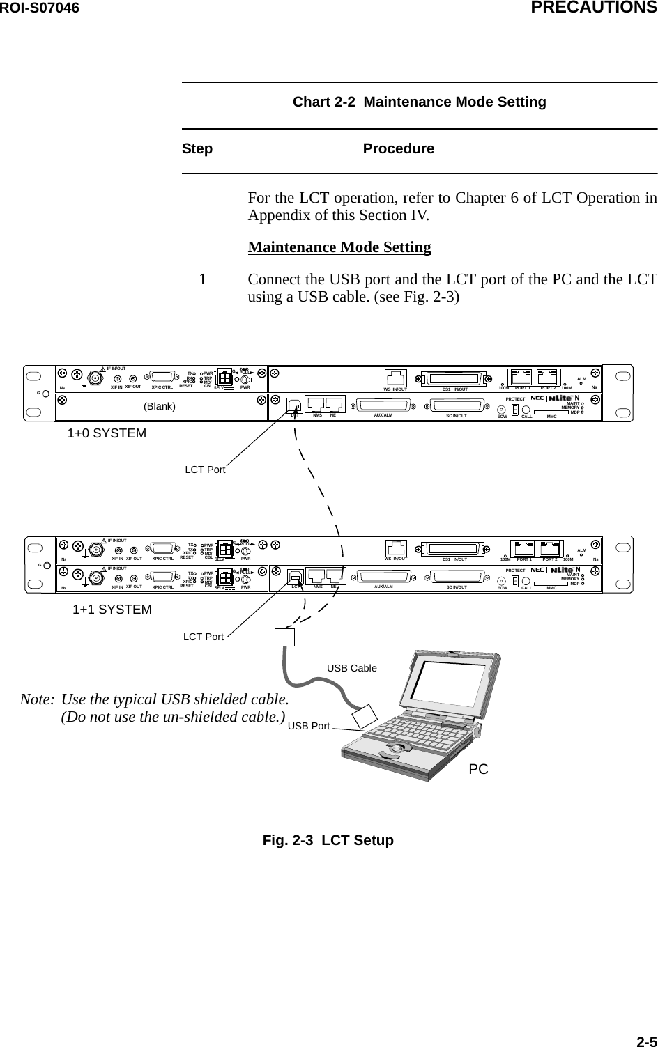
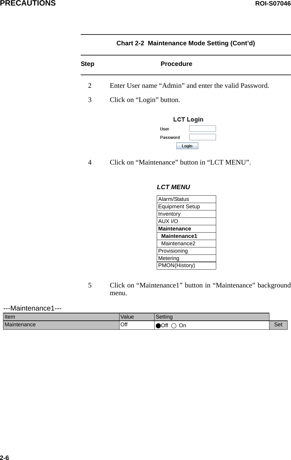
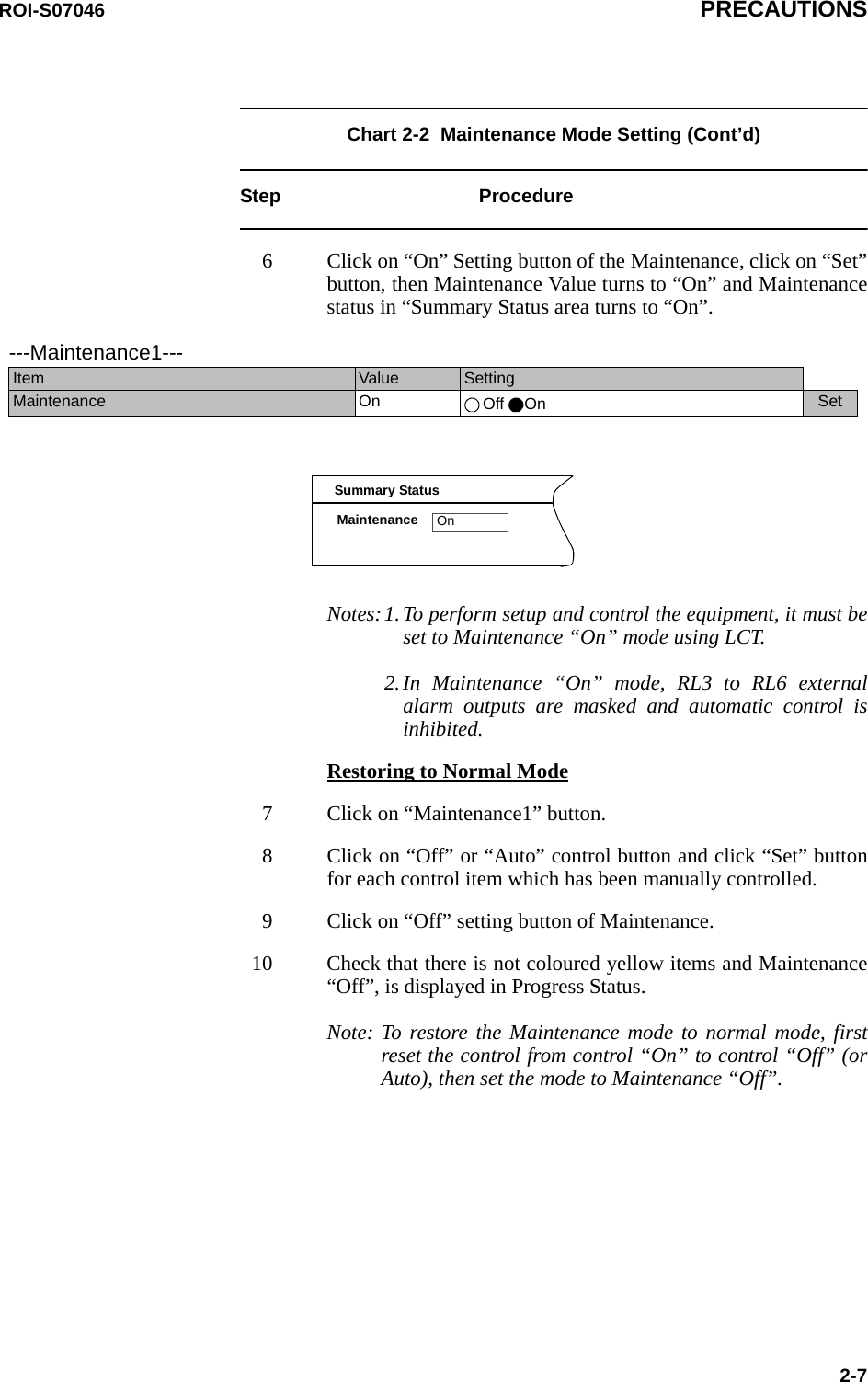
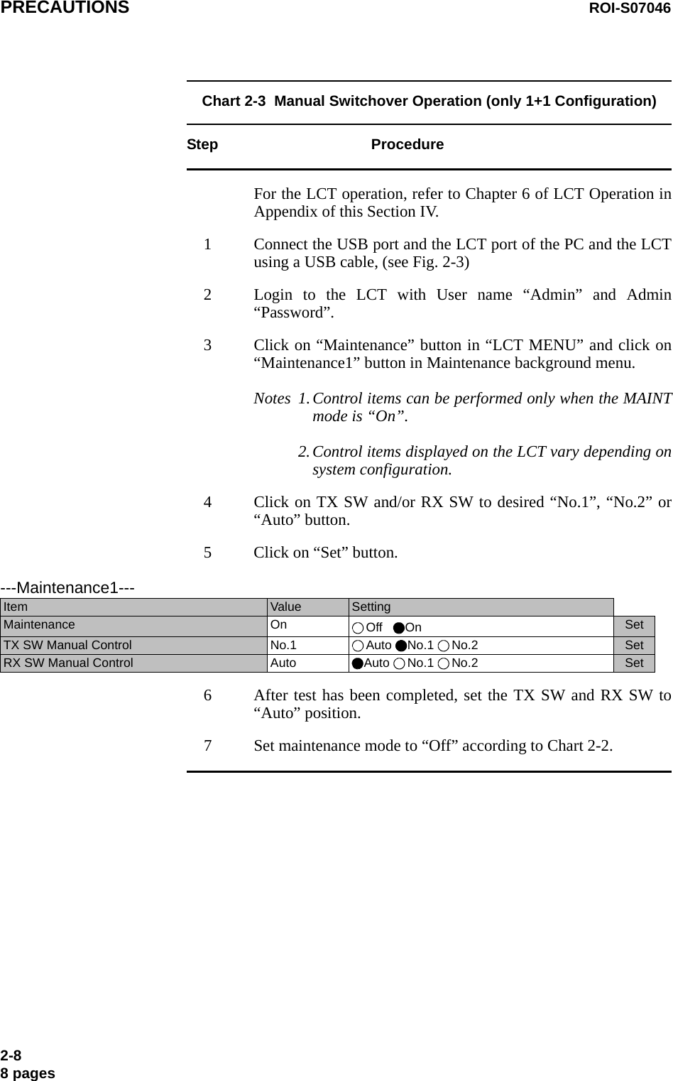
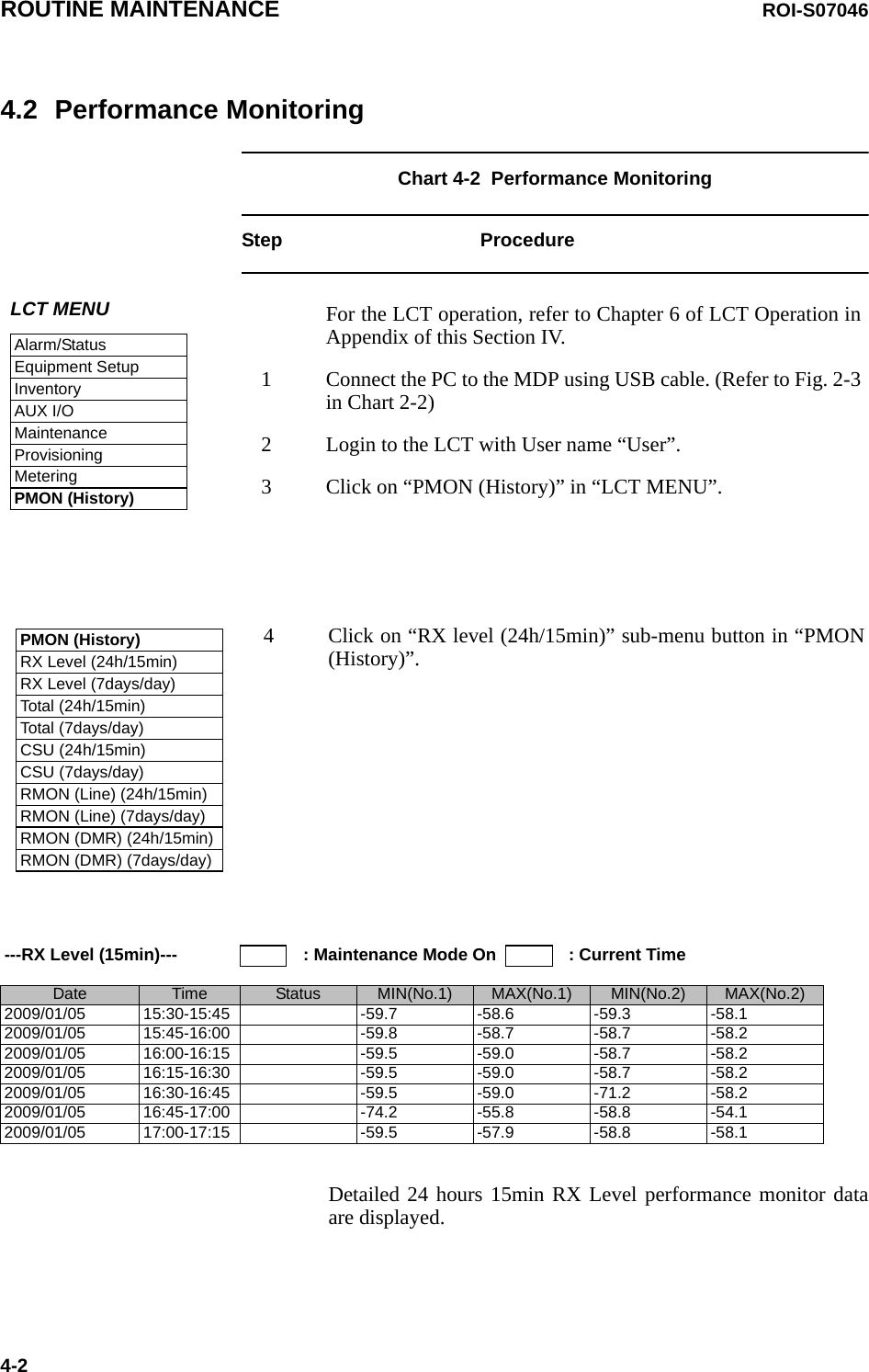
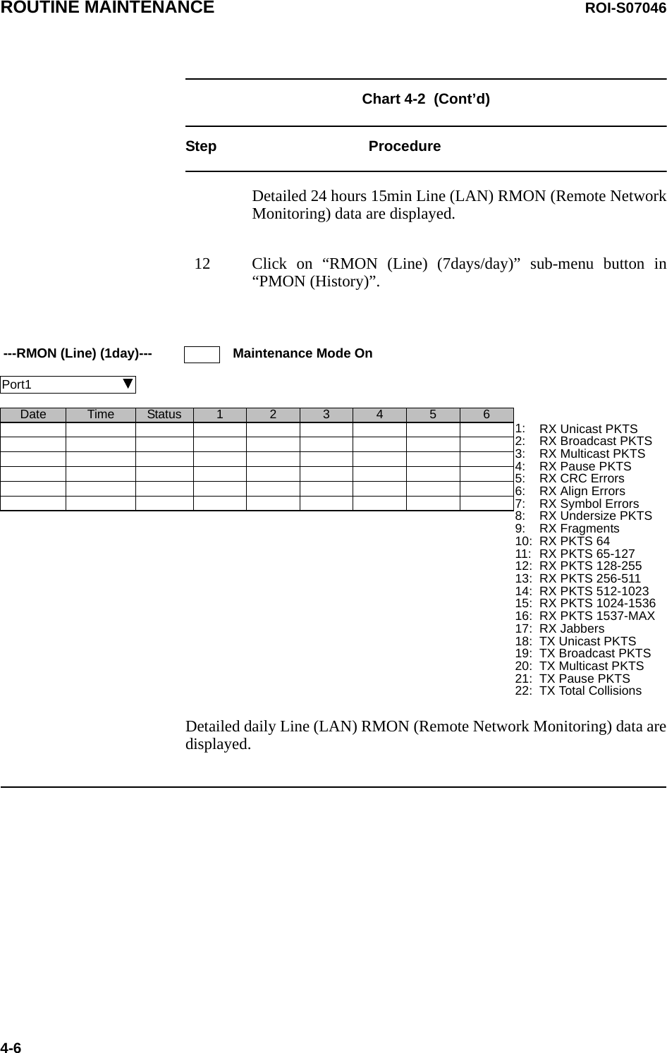
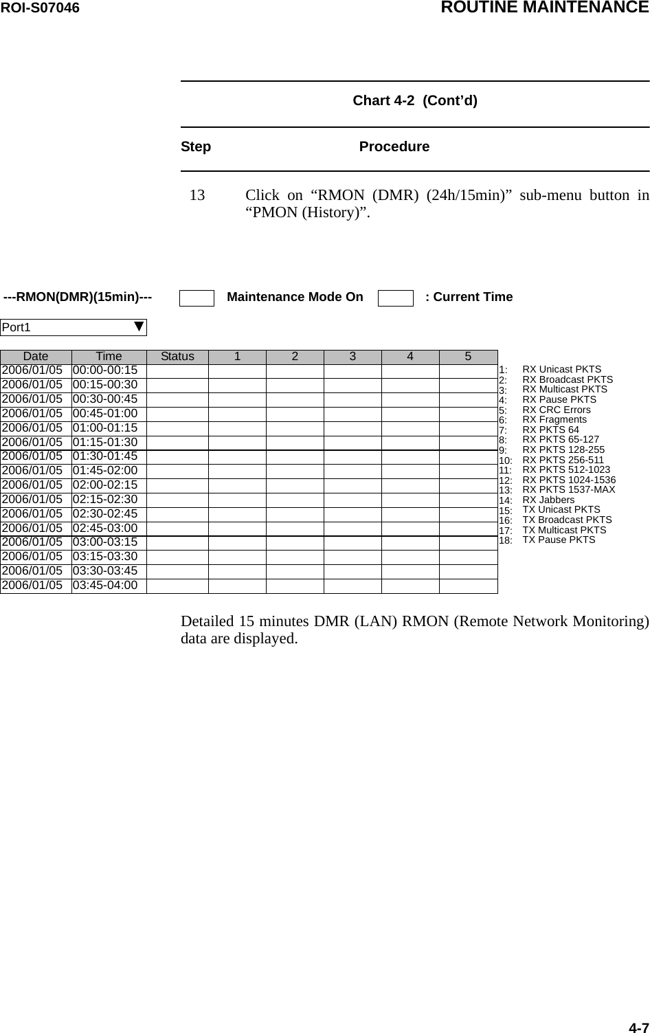
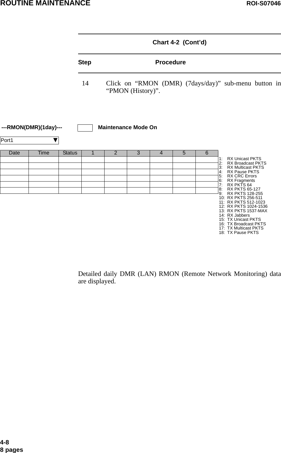
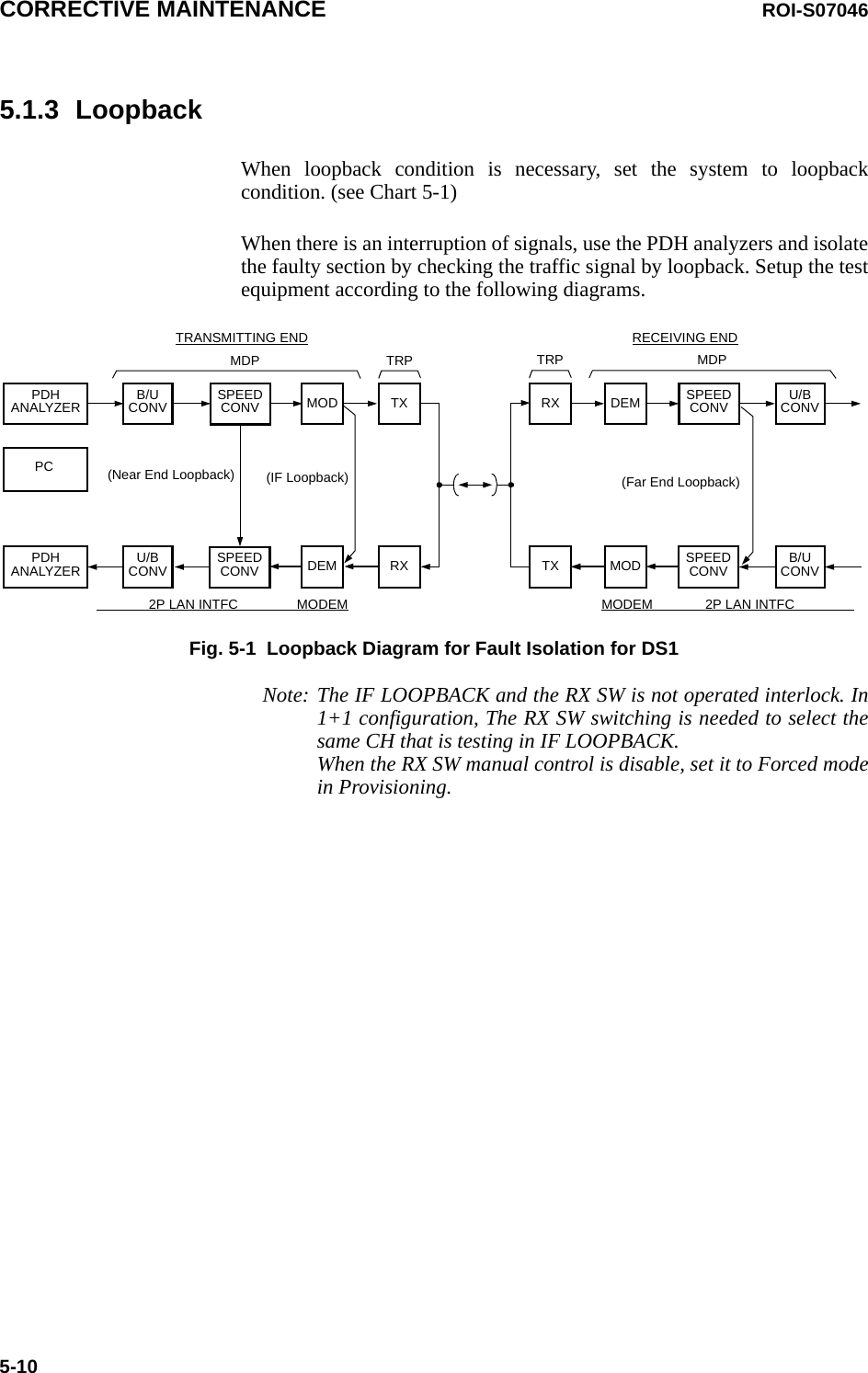
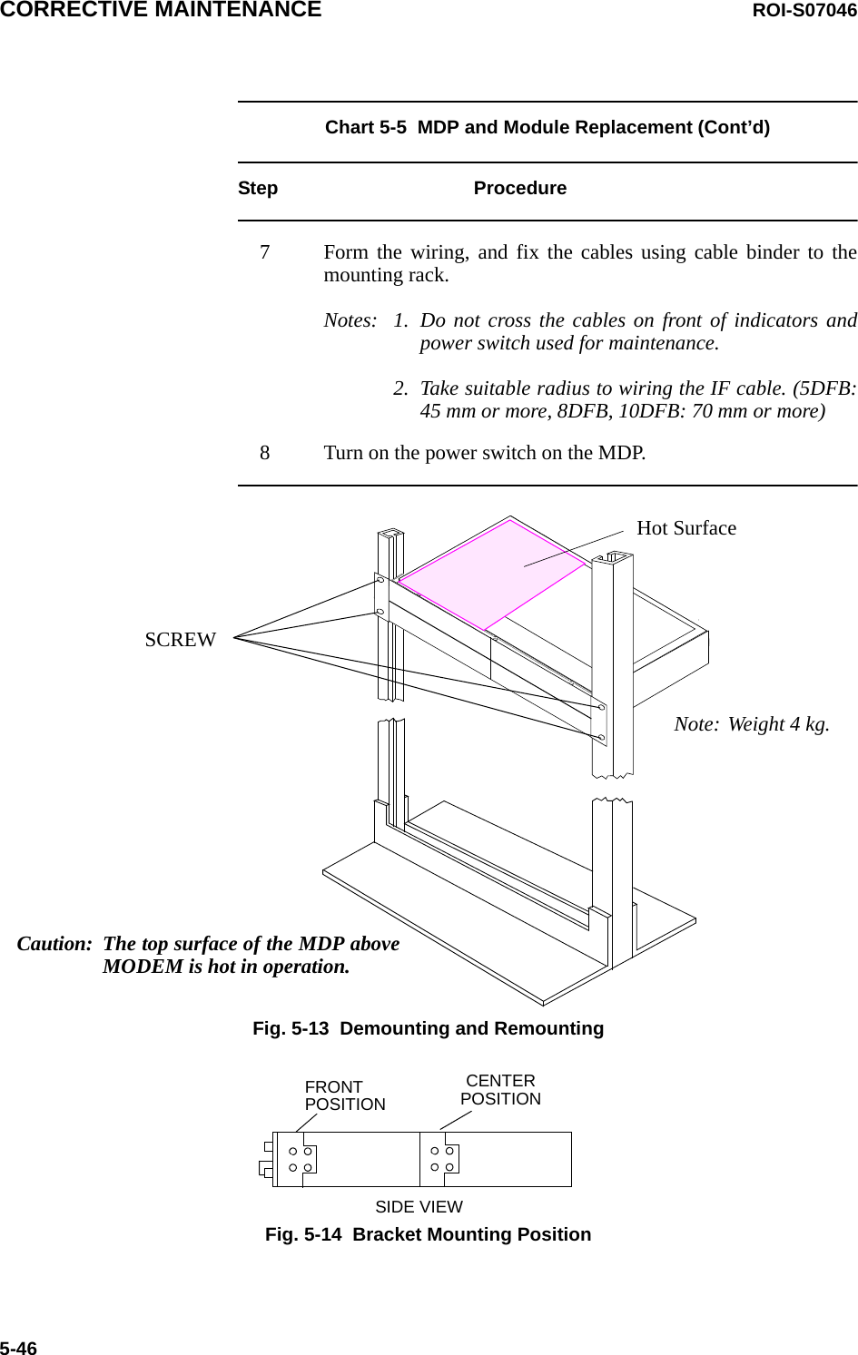
![ROI-S07046 ROUTINE MAINTENANCE4-14. ROUTINE MAINTENANCEThis chapter provides the routine (annually) maintenance procedures toensure the satisfactory operation of the equipment. During routinemaintenance, carefully observe the precautions given in Chapter 2.4.1 Meter Reading Chart 4-1 Meter ReadingStep ProcedureNotes:1. If an abnormal indication appears, check Alarm/Status, performance monitor and perform loopbacktest to distinguish sections of normal and alarmed.2. RX LEV varies depending on received RF signal level.3. Power Supply voltage at TRP/ALL INDOOR TRPvaries depending on IF cable length between theMDP and TRP/ALL INDOOR TRP.4. During total number of erroneous bits and totalnumber of correctly received bits are calculating,“Calculating” is displayed.5. 1.0E-10 is indicted equal to 1 x 10⁻¹⁰. ----Metering---No.1 No.2TX Power [dBm] +0.7 *RX Level [dBm] -65.2 -70.0TRP Power Supply [V] -45 -45BER 1.0E-10 CalculatingLCT MENUAlarm/StatusEquipment SetupInventoryAUX I/OMaintenanceProvisioningMeteringPMON (History)For the LCT operation, refer to Chapter 6 of LCT Operation inAppendix of this Section IV.1 Connect the PC to the MDP using USB cable. (Refer to Fig. 2-3in Chart 2-2)2 Login to the LCT with User name “User”.3 Click on “Metering” button in “LCT MENU”.](https://usermanual.wiki/NEC-of-America/58155N.User-Manual-Part-IV/User-Guide-1263944-Page-15.png)