NEC of America 58155N NLite N 5.8 GHz Digital Microwave Radio User Manual lan
NEC Corporation of America NLite N 5.8 GHz Digital Microwave Radio lan
UserManual.wiki
>
NEC of America
>
58155N User Manual
>
User Manual - Part VI
Contents
1.
User Manual - Part I
2.
User Manual - Part II
3.
User Manual - Part III
4.
User Manual - Part IV
5.
User Manual - Part V
6.
User Manual - Part VI
User Manual - Part VI
Navigation menu
Upload a User Manual
Namespaces
Wiki Guide
HTML
PDF
Info
Views
User Manual
Discussion / Help
Navigation
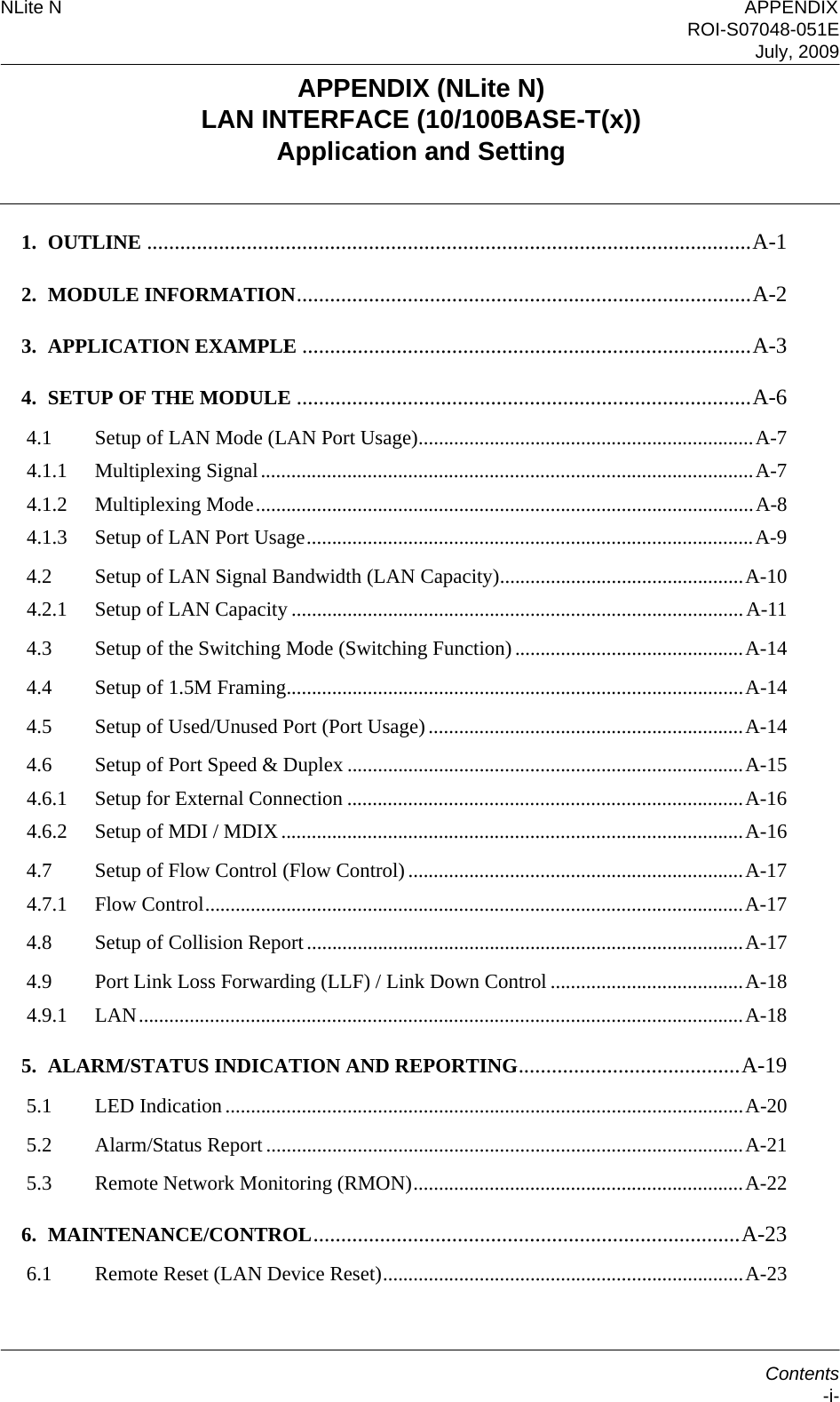

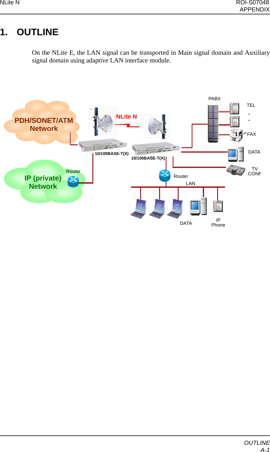
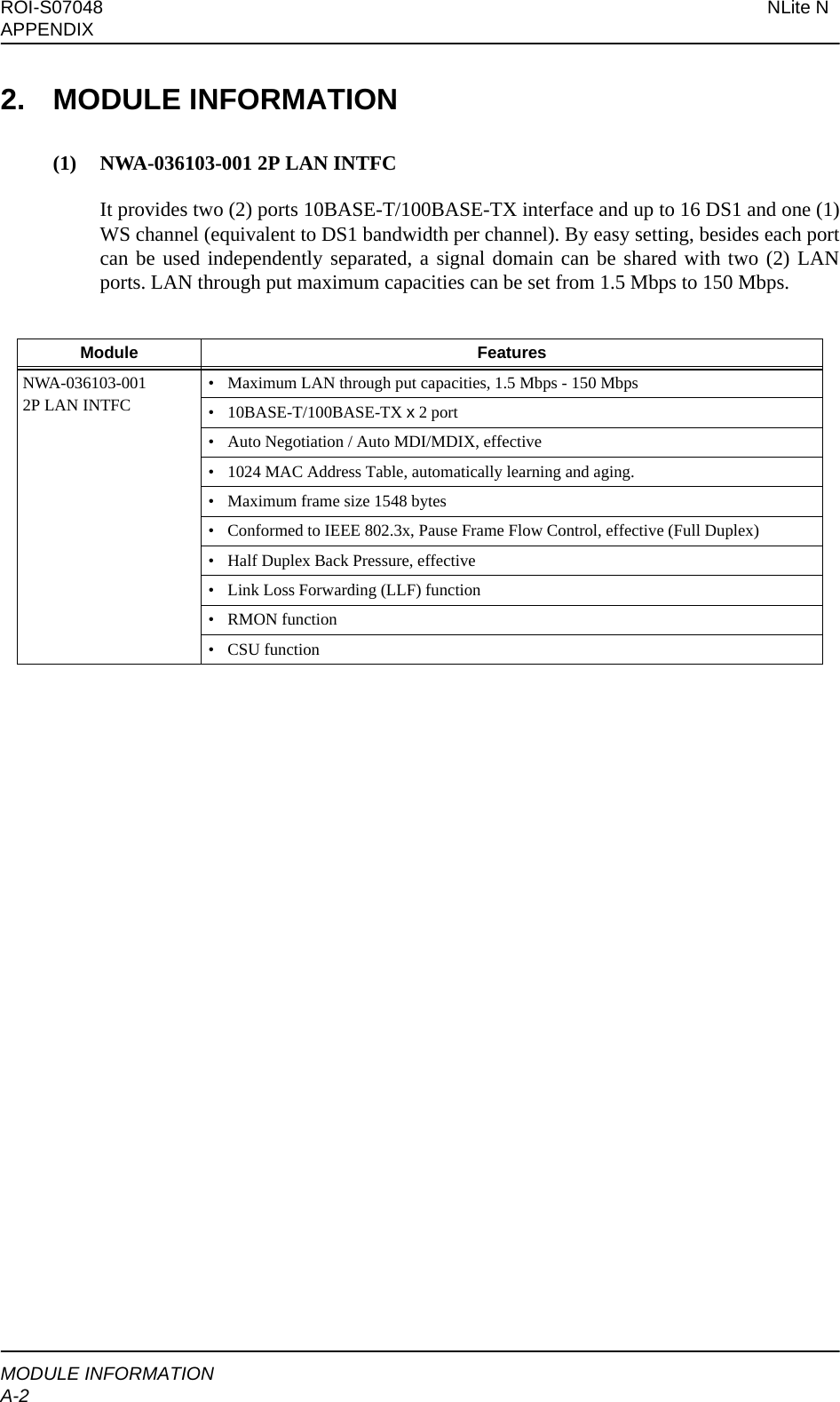
![NLite N ROI-S07048APPENDIXAPPLICATION EXAMPLEA-33. APPLICATION EXAMPLEThe LAN signal transmission mode in the radio section is described as follows. Applicabletransmission mode is depending on the interface module type as listed in the followingtable.Note: √: Applicable —: Not Applicable(1) Guaranteed Bandwidth ModeTwo (2) ports are completely separated and guaranteed maximum throughput for each port.[Setup] (e.g. 2P LAN INTFC)[Equipment Setup]→[LAN Port Usage]: P1:P2 = 1:0P1:P2 = 1:1Best EffortP1 = Fixed/P2P1 OnlyP1-2 SeparatedModuleMode(1) Guaranteed Bandwidth (2) Switching HUB (3) Data Distribution (4) BestEffort (5) DS1 Network Connection2P LAN INTFC √√√√ √Customer-A[Separated Mode](Port 1)NLite N(Port 1)Customer-B(Port 2)(Port 2)Traffics in Port1 and Port2 are completely independent. NLite N](https://usermanual.wiki/NEC-of-America/58155N.User-Manual-Part-VI/User-Guide-1263946-Page-5.png)
![ROI-S07048 NLite NAPPENDIXAPPLICATION EXAMPLEA-4(2) Switching HUB ModeBetween distant sites are connected with switching HUB configuration.[Setup] (e.g. 2P LAN INTFC)[Equipment Setup]→[LAN Port Usage]: P1-2 Shared / 1 Port Only (Main)[Provisioning]→[LAN Port Setting]→[Switching Function]: Enabled(3) DATA Distribution ModeMake up 1 vs. 2 asymmetry network composition like below connecting data center andterminals.[Setup] (e.g. 2P LAN INTFC)[Equipment Setup]→[LAN Port Usage]: P1-2 Shared / 1 Port Only (Main)[Provisioning]→[LAN Port Setting]→[Switching Function]: DisabledNLite N[Shared (Switching Enabled) Mode](Port 2)(Port 1)User-3User-4NLite N(Port 2)(Port 1)User-1User-2NLite N NLite NData Server(Port 1)(Port 2)(Port 1)(Port 2: DISABLE)User-1User-2[Shared (Switching Disabled) Mode]](https://usermanual.wiki/NEC-of-America/58155N.User-Manual-Part-VI/User-Guide-1263946-Page-6.png)
![NLite N ROI-S07048APPENDIXAPPLICATION EXAMPLEA-5(4) Best Effort ModeTwo (2) ports are separated and the signal band is shared in accordance with the trafficquantity of each port.It applies total transmission capacities for LAN in the radio section. It does not guaranteedfor each port.[Setup] (e.g. 2P LAN INTFC)[Equipment Setup]→[LAN Port Usage]: Best Effort(5) DS1 Network Connection ModeMake up LAN network via DS1 network.[Setup] (e.g. 2P LAN INTFC)Notes: 1. Set to LAN Enabled at the ST-A and ST-D stations, set to 1.5M at the ST-B andST-C stations.2. LAN → DS1 (1.5 Mbps) and DS1 (1.5 Mbps) → LAN conversion must beperformed through the NLite N.At ST-A / ST-D[Equipment Setup]→[LAN Port Usage]: P1 = Fixed/P2[Equipment Setup]→[LAN Capacity2]: P2: 1.5 MbpsAt ST-B / ST-C[Equipment Setup]→[LAN Port Usage]: P1:P2 = 1:0 NLite N[Best Effort Mode](Port 2)(Port 1)NLite N(Port 2)(Port 1)Customer-ACustomer-BNLite NST-D (LAN)NLite NST-C (1.5M)NLite NST-A (LAN)NLite NST-B (1.5M)Router-1Router-2DS1 Network](https://usermanual.wiki/NEC-of-America/58155N.User-Manual-Part-VI/User-Guide-1263946-Page-7.png)

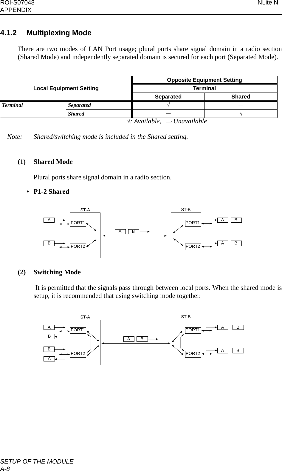
![NLite N ROI-S07048APPENDIXSETUP OF THE MODULEA-9(3) Separated ModeIt is secured signal domain for each independent port.• P1:P2 = 1:0, P1:P2 = 1:1, Best Effort, P1 = Fixed/P2, P1 Only, P1-2 Separated4.1.3 Setup of LAN Port Usage[LAN Port Usage Setup][Equipment Setup]→[LAN Port Usage](1) 2P LAN INTFCNo. Setup Description1P1:P2 = 1:0 Bandwidth ratio between Port1 and Port2 is 1:0.2P1:P2 = 1:1 Bandwidth ratio between Port1 and Port2 is 1:1.3Best Effort Bandwidth ratio between Port1 and Port2 is best effort.4P1 = Fixed/P2 Port 1 (P1) is fixed bandwidth; P2 is valuable bandwidth.5P1-2 Shared/1Port Only (Main) Selecting when only one (1) port is used or bandwidth is shared in port1 and port2. The LAN signal is transmitted in the Main signal domain.6P1 Only (Main) Selecting when only port1 is used. The LAN signal is transmitted in the Main signal domain.7P1-2 Separated (Main) Selecting when each port is used independently separated. The LAN signal is transmitted in the Main signal domain.8P1-2 Separated (Main + WS) Selecting when each port is used independently separated. The LAN signal is transmitted in the Main and WS signal domain.9P1-2 Separated (Main + SC) Selecting when each port is used independently separated. The LAN signal is transmitted in the Main and SC signal domain.10 Not Used The LAN transmission is not applied.PORT2PORT1BAPORT2PORT1BAST-BST-AAB](https://usermanual.wiki/NEC-of-America/58155N.User-Manual-Part-VI/User-Guide-1263946-Page-11.png)
![ROI-S07048 NLite NAPPENDIXSETUP OF THE MODULEA-104.2 Setup of LAN Signal Bandwidth (LAN Capacity)Setting of bandwidth for the LAN signal transmission. Settable bandwidth varies depending on the Transmission Capacity selection and LAN PortUsage setup.Selectable bandwidth and shared signal domain of the LAN signal are given in following tables.The codes are used for System Configuration and Channel Assignment in the table, refer infollowing Table a. and Table b.a. System Configuration Setup Codeb. Channel Assignment CodeNote: “L”, “L1” and “L2”, italic and bold characters in Setup of LAN Capacity tables, can select1.5M Framing function.4.2.1 Setup of LAN Capacity[LAN Capacity Setup][Equipment Setup] → [LAN Capacity]Code LAN Port Usage[A-1] P1-2 Shared/1Port Only (Main)[A-2] P1:P2 = 1:0P1:P2 = 1:1Best EffortP1 = Fixed/P2P1 Only (Main)P1-2 Separated (Main)[A-3] P1-2 Separated (Main + WS)[A-4] P1-2 Separated (Main + SC)Code DescriptionDS1 1.544 Mbps (DS1) DataL1 LAN Port1L2 LAN Port2L* LAN (P1:P2 = 1:0, P1:P2 = 1:1, Best Effort)L LAN (Shared)S V.11/RS-232C Data- Not Assignable](https://usermanual.wiki/NEC-of-America/58155N.User-Manual-Part-VI/User-Guide-1263946-Page-12.png)
![NLite N ROI-S07048APPENDIXSETUP OF THE MODULEA-11(1) 2P LAN INTFCNote: “L2”: Highlighted in a box: can select 1.5M Framing function.• 28 × DS1/64 QAM (Transmission Capacity : 42 Mbps) System Configuration LAN Capacity[bps]Channel AssignmentMain Traffic WS SCPort1Port21 2 3 4 5 6 7 8 9 10111213141516171819202122232425262728 1 1 2 3 4Not Used - - DS1 DS1 DS1 DS1 DS1 DS1 DS1 DS1 DS1 DS1 DS1 DS1 DS1 DS1 DS1 DS1 / / / / / / / / / / / / DS1 S S S SA-1 [Shared Main]18M DS1 DS1 DS1 DS1 DS1 DS1 DS1 DS1 DS1 DS1 DS1 DS1 DS1 DS1 DS1 DS1 LLLLLLLLLLLLDS1SSSS19.5M DS1 DS1 DS1 DS1 DS1 DS1 DS1 DS1 DS1 DS1 DS1 DS1 DS1 DS1 DS1 L L L L L L L L L L L L LDS1SSSS21M DS1 DS1 DS1 DS1 DS1 DS1 DS1 DS1 DS1 DS1 DS1 DS1 DS1 DS1 LLLLLLLLLLLLLLDS1SSSS22.5M DS1 DS1 DS1 DS1 DS1 DS1 DS1 DS1 DS1 DS1 DS1 DS1 DS1 LLLLLLLLLLLLLLLDS1SSSS24M DS1 DS1 DS1 DS1 DS1 DS1 DS1 DS1 DS1 DS1 DS1 DS1 LLLLLLLLLLLLLLLLDS1SSSS25.5M DS1 DS1 DS1 DS1 DS1 DS1 DS1 DS1 DS1 DS1 DS1 LLLLLLLLLLLLLLLLLDS1SSSS27M DS1 DS1 DS1 DS1 DS1 DS1 DS1 DS1 DS1 DS1 LLLLLLLLLLLLLLLLLLDS1SSSS28.5M DS1 DS1 DS1 DS1 DS1 DS1 DS1 DS1 DS1 LLLLLLLLLLLLLLLLLLLDS1SSSS30M DS1 DS1 DS1 DS1 DS1 DS1 DS1 DS1 LLLLLLLLLLLLLLLLLLLLDS1SSSS31.5M DS1 DS1 DS1 DS1 DS1 DS1 DS1 LLLLLLLLLLLLLLLLLLLLLDS1SSSS33M DS1 DS1 DS1 DS1 DS1 DS1 LLLLLLLLLLLLLLLLLLLLLLDS1SSSS34.5M DS1 DS1 DS1 DS1 DS1 LLLLLLLLLLLLLLLLLLLLLLLDS1SSSS36M DS1 DS1 DS1 DS1 LLLLLLLLLLLLLLLLLLLLLLLLDS1SSSS37.5M DS1 DS1 DS1 LLLLLLLLLLLLLLLLLLLLLLLLLDS1SSSS39M DS1 DS1 LLLLLLLLLLLLLLLLLLLLLLLLLLDS1SSSS40.5M DS1 LLLLLLLLLLLLLLLLLLLLLLLLLLLDS1SSSS42M LLLLLLLLLLLLLLLLLLLLLLLLLLLLDS1SSSSA-2 [Main+Main]18M - DS1 DS1 DS1 DS1 DS1 DS1 DS1 DS1 DS1 DS1 DS1 DS1 DS1 DS1 DS1 DS1 L1 L1 L1 L1 L1 L1 L1 L1 L1 L1 L1 L1 DS1 S S S S42M - L1 L1 L1 L1 L1 L1 L1 L1 L1 L1 L1 L1 L1 L1 L1 L1 L1 L1 L1 L1 L1 L1 L1 L1 L1 L1 L1 L1 DS1 S S S S9M 9M DS1 DS1 DS1 DS1 DS1 DS1 DS1 DS1 DS1 DS1 DS1 DS1 DS1 DS1 DS1 DS1 L2 L2 L2 L2 L2 L2 L1 L1 L1 L1 L1 L1 DS1 S S S S21M 21M L2 L2 L2 L2 L2 L2 L2 L2 L2 L2 L2 L2 L2 L2 L1 L1 L1 L1 L1 L1 L1 L1 L1 L1 L1 L1 L1 L1 DS1 S S S SA-3 [Main+WS] 18M 1.5M DS1 DS1 DS1 DS1 DS1 DS1 DS1 DS1 DS1 DS1 DS1 DS1 DS1 DS1 DS1 DS1 L1 L1 L1 L1 L1 L1 L1 L1 L1 L1 L1 L1 L2 SSSS42M 1.5M L1 L1 L1 L1 L1 L1 L1 L1 L1 L1 L1 L1 L1 L1 L1 L1 L1 L1 L1 L1 L1 L1 L1 L1 L1 L1 L1 L1 L2 SSSSA-4 [Main+SC]18M 64K DS1 DS1 DS1 DS1 DS1 DS1 DS1 DS1 DS1 DS1 DS1 DS1 DS1 DS1 DS1 DS1 L1 L1 L1 L1 L1 L1 L1 L1 L1 L1 L1 L1 DS1 L2 S S S18M 128K DS1 DS1 DS1 DS1 DS1 DS1 DS1 DS1 DS1 DS1 DS1 DS1 DS1 DS1 DS1 DS1 L1 L1 L1 L1 L1 L1 L1 L1 L1 L1 L1 L1 DS1 L2 L2 S S18M 256K DS1 DS1 DS1 DS1 DS1 DS1 DS1 DS1 DS1 DS1 DS1 DS1 DS1 DS1 DS1 DS1 L1 L1 L1 L1 L1 L1 L1 L1 L1 L1 L1 L1 DS1 L2 L2 L2 L242M 64K L1 L1 L1 L1 L1 L1 L1 L1 L1 L1 L1 L1 L1 L1 L1 L1 L1 L1 L1 L1 L1 L1 L1 L1 L1 L1 L1 L1 DS1 L2 S S S42M 128K L1 L1 L1 L1 L1 L1 L1 L1 L1 L1 L1 L1 L1 L1 L1 L1 L1 L1 L1 L1 L1 L1 L1 L1 L1 L1 L1 L1 DS1 L2 L2 S S42M 256K L1 L1 L1 L1 L1 L1 L1 L1 L1 L1 L1 L1 L1 L1 L1 L1 L1 L1 L1 L1 L1 L1 L1 L1 L1 L1 L1 L1 DS1 L2 L2 L2 L2](https://usermanual.wiki/NEC-of-America/58155N.User-Manual-Part-VI/User-Guide-1263946-Page-13.png)
![ROI-S07048 NLite NAPPENDIXSETUP OF THE MODULEA-12Note: “L2”: Highlighted in a box: can select 1.5M Framing function.• 32 × DS1/QPSK (Transmission Capacity : 48 Mbps)System Configuration LAN Capacity[bps]Channel AssignmentMain Traffic WS SCPort1Port2123456789101112131415161718192021222324252627282930313211234Not Used - -DS1DS1DS1DS1DS1DS1DS1DS1DS1DS1DS1DS1DS1DS1DS1DS1////////////////DS1SSSSA-1 [Shared Main]24M DS1 DS1 DS1 DS1 DS1 DS1 DS1 DS1 DS1 DS1 DS1 DS1 DS1 DS1 DS1 DS1 LLLLLLLLLLLLLLLLDS1SSSS25.5M DS1 DS1 DS1 DS1 DS1 DS1 DS1 DS1 DS1 DS1 DS1 DS1 DS1 DS1 DS1 LLLLLLLLLLLLLLLLLDS1SSSS27M DS1 DS1 DS1 DS1 DS1 DS1 DS1 DS1 DS1 DS1 DS1 DS1 DS1 DS1 LLLLLLLLLLLLLLLLLLDS1SSSS28.5M DS1 DS1 DS1 DS1 DS1 DS1 DS1 DS1 DS1 DS1 DS1 DS1 DS1 LLLLLLLLLLLLLLLLLLLDS1SSSS30M DS1 DS1 DS1 DS1 DS1 DS1 DS1 DS1 DS1 DS1 DS1 DS1 LLLLLLLLLLLLLLLLLLLLDS1SSSS31.5M DS1 DS1 DS1 DS1 DS1 DS1 DS1 DS1 DS1 DS1 DS1 LLLLLLLLLLLLLLLLLLLLLDS1SSSS33M DS1 DS1 DS1 DS1 DS1 DS1 DS1 DS1 DS1 DS1 LLLLLLLLLLLLLLLLLLLLLLDS1SSSS34.5M DS1 DS1 DS1 DS1 DS1 DS1 DS1 DS1 DS1 LLLLLLLLLLLLLLLLLLLLLLLDS1SSSS36M DS1 DS1 DS1 DS1 DS1 DS1 DS1 DS1 LLLLLLLLLLLLLLLLLLLLLLLLDS1SSSS37.5M DS1 DS1 DS1 DS1 DS1 DS1 DS1 LLLLLLLLLLLLLLLLLLLLLLLLLDS1SSSS39M DS1 DS1 DS1 DS1 DS1 DS1 LLLLLLLLLLLLLLLLLLLLLLLLLLDS1SSSS40.5M DS1 DS1 DS1 DS1 DS1 LLLLLLLLLLLLLLLLLLLLLLLLLLLDS1SSSS42M DS1 DS1 DS1 DS1 LLLLLLLLLLLLLLLLLLLLLLLLLLLLDS1SSSS43.5M DS1 DS1 DS1 LLLLLLLLLLLLLLLLLLLLLLLLLLLLLDS1SSSS45M DS1 DS1 LLLLLLLLLLLLLLLLLLLLLLLLLLLLLLDS1SSSS46.5M DS1 LLLLLLLLLLLLLLLLLLLLLLLLLLLLLLLDS1SSSS48M LLLLLLLLLLLLLLLLLLLLLLLLLLLLLLLLDS1SSSSA-2 [Main+Main]24M - DS1 DS1 DS1 DS1 DS1 DS1 DS1 DS1 DS1 DS1 DS1 DS1 DS1 DS1 DS1 DS1 L1 L1 L1 L1 L1 L1 L1 L1 L1 L1 L1 L1 L1 L1 L1 L1DS1SSSS48M - L1 L1 L1 L1 L1 L1 L1 L1 L1 L1 L1 L1 L1 L1 L1 L1 L1 L1 L1 L1 L1 L1 L1 L1 L1 L1 L1 L1 L1 L1 L1 L1DS1SSSS12M 12M DS1 DS1 DS1 DS1 DS1 DS1 DS1 DS1 DS1 DS1 DS1 DS1 DS1 DS1 DS1 DS1 L2 L2 L2 L2 L2 L2 L2 L2 L1 L1 L1 L1 L1 L1 L1 L1DS1SSSS24M 24M L2 L2 L2 L2 L2 L2 L2 L2 L2 L2 L2 L2 L2 L2 L2 L2 L1 L1 L1 L1 L1 L1 L1 L1 L1 L1 L1 L1 L1 L1 L1 L1DS1SSSSA-3 [Main+WS]24M 1.5M DS1 DS1 DS1 DS1 DS1 DS1 DS1 DS1 DS1 DS1 DS1 DS1 DS1 DS1 DS1 DS1 L1 L1 L1 L1 L1 L1 L1 L1 L1 L1 L1 L1 L1 L1 L1 L1 L2 SSSS48M 1.5M L1 L1 L1 L1 L1 L1 L1 L1 L1 L1 L1 L1 L1 L1 L1 L1 L1 L1 L1 L1 L1 L1 L1 L1 L1 L1 L1 L1 L1 L1 L1 L1 L2 SSSSA-4 [Main+SC]24M 64K DS1 DS1 DS1 DS1 DS1 DS1 DS1 DS1 DS1 DS1 DS1 DS1 DS1 DS1 DS1 DS1 L1 L1 L1 L1 L1 L1 L1 L1 L1 L1 L1 L1 L1 L1 L1 L1 DS1 L2SSS24M 128K DS1 DS1 DS1 DS1 DS1 DS1 DS1 DS1 DS1 DS1 DS1 DS1 DS1 DS1 DS1 DS1 L1 L1 L1 L1 L1 L1 L1 L1 L1 L1 L1 L1 L1 L1 L1 L1 DS1 L2 L2 S S24M 256K DS1 DS1 DS1 DS1 DS1 DS1 DS1 DS1 DS1 DS1 DS1 DS1 DS1 DS1 DS1 DS1 L1 L1 L1 L1 L1 L1 L1 L1 L1 L1 L1 L1 L1 L1 L1 L1 DS1 L2 L2 L2 L248M 64K L1 L1 L1 L1 L1 L1 L1 L1 L1 L1 L1 L1 L1 L1 L1 L1 L1 L1 L1 L1 L1 L1 L1 L1 L1 L1 L1 L1 L1 L1 L1 L1 DS1 L2SSS48M 128K L1 L1 L1 L1 L1 L1 L1 L1 L1 L1 L1 L1 L1 L1 L1 L1 L1 L1 L1 L1 L1 L1 L1 L1 L1 L1 L1 L1 L1 L1 L1 L1 DS1 L2 L2 S S48M 256K L1 L1 L1 L1 L1 L1 L1 L1 L1 L1 L1 L1 L1 L1 L1 L1 L1 L1 L1 L1 L1 L1 L1 L1 L1 L1 L1 L1 L1 L1 L1 L1 DS1 L2 L2 L2 L2](https://usermanual.wiki/NEC-of-America/58155N.User-Manual-Part-VI/User-Guide-1263946-Page-14.png)
![NLite N ROI-S07048APPENDIXSETUP OF THE MODULEA-13Note: “L2”: Highlighted in a box: can select 1.5M Framing function.•1 × OC-3/16 QAM, 1 × OC-3/64 QAM, 1 × OC-3/128 QAM (Transmission Capacity : 150 Mbps)System ConfigurationLAN Capacity[bps]Channel AssignmentMain Traffic WS SCPort1Port21234567891011121314151626M100M 11234Not Used --DS1DS1DS1DS1DS1DS1DS1DS1DS1DS1DS1DS1DS1DS1DS1DS1/ /DS1SSSSA-2[Main+Main]100M - DS1 DS1 DS1 DS1 DS1 DS1 DS1 DS1 DS1 DS1 DS1 DS1 DS1 DS1 DS1 DS1 / L*DS1SSSS63M 63M DS1 DS1 DS1 DS1 DS1 DS1 DS1 DS1 DS1 DS1 DS1 DS1 DS1 DS1 DS1 DS1 L* L*DS1SSSS75M 75M L* L* L* L* L* L* L* L* L* L* L* L* L* L* L* L* L* L*DS1SSSS150M L* L* L* L* L* L* L* L* L* L* L* L* L* L* L* L* L* L*DS1SSSS100M 1.5M DS1 DS1 DS1 DS1 DS1 DS1 DS1 DS1 DS1 DS1 DS1 DS1 DS1 DS1 DS1 L2 /L1DS1SSSS100M 26M DS1 DS1 DS1 DS1 DS1 DS1 DS1 DS1 DS1 DS1 DS1 DS1 DS1 DS1 DS1 DS1 L2 L1DS1SSSS100M 50M L2 L2 L2 L2 L2 L2 L2 L2 L2 L2 L2 L2 L2 L2 L2 L2 L2 L1DS1SSSSA-3[Main+WS] 100M 1.5M DS1 DS1 DS1 DS1 DS1 DS1 DS1 DS1 DS1 DS1 DS1 DS1 DS1 DS1 DS1 DS1 / L1 L2 SSSS](https://usermanual.wiki/NEC-of-America/58155N.User-Manual-Part-VI/User-Guide-1263946-Page-15.png)
![ROI-S07048 NLite NAPPENDIXSETUP OF THE MODULEA-144.3 Setup of the Switching Mode (Switching Function)This is switching mode setup between local ports which share domain, that is available only onthe shared mode.[Switching Function Setup][Provisioning]→[LAN Port Setup]→[Switching Function]4.4 Setup of 1.5M FramingWhen the LAN bandwidth is set to 1.5 Mbps, DS1 framing corresponded to ANSI T1.403 isavailable in the transmission data in the radio link.4.5 Setup of Used/Unused Port (Port Usage)This is the setup of the used or unused LAN port.[Port Usage Setup][Provisioning]→[LAN Port Setup]→ [Port Usage]Note: When Not Used is selected, link of port is compulsorily released.No. Setup Descriptions1Enabled Enables data communication between local ports which share domain.2Disabled (Default) Disables data communication between local ports which share domain.No. Setup Descriptions1UF (Unframed) Framing is not effected.All 1.5 Mbps are used for LAN signal bandwidth.2SF (ANSI T1.107) Framing is effected for Superframe frame.3ESF (ANSI T1.107) Framing is effected for Extended Superframe frame.No. Setup Descriptions1Used Port is used.2Not Used (Default) Port is not used.](https://usermanual.wiki/NEC-of-America/58155N.User-Manual-Part-VI/User-Guide-1263946-Page-16.png)
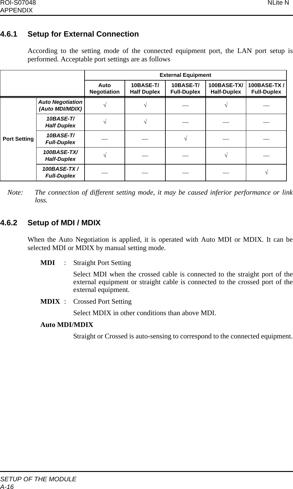
![NLite N ROI-S07048APPENDIXSETUP OF THE MODULEA-154.6 Setup of Port Speed & DuplexThis is the setup of the operation mode of LAN port.1) 10/100BASE-TX Supported port [Speed & Duplex Setup][Provisioning]→[LAN Port Setup]→[Speed & Duplex]No. Mode Descriptions1AUTONEG (AUTO-MDI/MDIX)Auto-Negotiation (Auto-MDI/MDIX)(Default)Depending on the connecting NE, the setting of 10M / 100M, Half / Full and STRAIGHT / CROSSED are plugged in auto-sensing. 210M - HALF (MDI)10BASE-T HALF Duplex (MDI)For 10M Half-Duplex (MDI), set to fixed mode.310M - FULL (MDI)10BASE-T FULL Duplex (MDI)For 10M Full-Duplex (MDI), set to fixed mode. 4100M - HALF (MDI)100BASE-TX HALF Duplex (MDI)For 100M Half-Duplex (MDI), set to fixed mode.5100M - FULL (MDI)100BASE-TX FULL Duplex (MDI)For 100M Full-Duplex (MDI), set to fixed mode.610M - HALF (MDIX)10BASE-T HALF Duplex (MDIX)For 10M Half-Duplex (MDIX), set to fixed mode.710M - FULL (MDIX)10BASE-T FULL Duplex (MDIX)For 10M Full-Duplex (MDIX), set to fixed mode.8100M - HALF (MDIX)100BASE-TX HALF Duplex (MDIX)For 100M Half-Duplex (MDIX), set to fixed mode.9100M - FULL (MDIX)100BASE-TX FULL Duplex (MDIX)For 100M Full-Duplex (MDIX), set to fixed mode.](https://usermanual.wiki/NEC-of-America/58155N.User-Manual-Part-VI/User-Guide-1263946-Page-17.png)
![NLite N ROI-S07048APPENDIXSETUP OF THE MODULEA-174.7 Setup of Flow Control (Flow Control)This is the setup of ON/OFF for the flow control function to each port. [Flow Control][Provisioning]→[LAN Port Setup]→[Flow Control]4.7.1 Flow ControlIn accordance with the Half/Full-Duplex mode, following two (2) flow control modes provide inthe INTFC module.4.8 Setup of Collision ReportIn HALF-Duplex mode, it is selected that is reported or not reported about collision conditions ateach port.[Collision Report][Provisioning]→[LAN Port Setup]→[Collision Report]Note: When the flow control is applied in HALF-Duplex mode, a collision condition may beoccurred while the Back Pressure control, therefore, use of “Not Reported” mode isrecommended.No. Setup Descriptions1On (Default) Flow control is operated.2Off Flow control is not operated.No. Mode Description of Flow Control System1Half-Duplex Back Pressure:To prevent frame inflow, it is caused pseudo-collision by sending jam signals.2Full-Duplex PAUSE frame Flow Control: By sending PAUSE frame (conformed to IEEE 802.3x), request the opposite equipment that the frame sending to be stopped/started. It is required that the opposite equipment also has this function.No. Setup Descriptions1Reported Collision condition is reported.2Not Reported (Default) Collision condition is not reported.](https://usermanual.wiki/NEC-of-America/58155N.User-Manual-Part-VI/User-Guide-1263946-Page-19.png)
![ROI-S07048 NLite NAPPENDIXSETUP OF THE MODULEA-184.9 Port Link Loss Forwarding (LLF) / Link Down Control4.9.1 LANThe function is provided for compulsorily release the local link by detecting opposite link failure.It can be set the control that it is enabled/disabled the function for each port.[Link loss Forwarding][Provisioning]→[LAN Port Setup]→[Link loss Forwarding]Notes: 1. When LOF/High BER alarm occurs in a radio section, regardless of above setup, link iscompulsorily released.2. When the Port Switching is set to Enabled, this function is not operated.4.9.1.1 Control of Releasing LinkThe function provides the control to release the link at both terminals when the radio sectionfailure or LAN port link failure occurs. a. Control of Compulsorily Released Link by Radio Channel FailureWhen radio section failure occurs, port link is compulsorily released for both endterminals. This function operates regardless of setting of the Loss Forwarding function.Note: The control is performed in accordance with the setting conditions of the AISActivation Condition. (Default: LOF + High BER Alarm)b. Control of Compulsorily Released Link by the Opposite Link FailureWhen the Link Loss Forwarding function is set to Enabled, the local link is compulsorilyreleased by detecting the link failure of the opposite station.No. Setup Descriptions1Enabled Enables the function to compulsorily release the local link by information from the opposite link.2Disabled(Default)Disables the function to compulsorily release the local link by information from the opposite link.Ethernet[ST-B]RadioEthernet[ST-A](local) (opposite)Ethernet[ST-B]RadioEthernet[ST-A](local) (opposite)](https://usermanual.wiki/NEC-of-America/58155N.User-Manual-Part-VI/User-Guide-1263946-Page-20.png)
![NLite N ROI-S07048APPENDIXMAINTENANCE/CONTROLA-236. MAINTENANCE/CONTROL6.1 Remote Reset (LAN Device Reset)It can be performed Reset control for LAN Port.[LAN Device Reset Control][Maintenance]→[Maintenance1]Note: *: Not performed when in normal operation.Link failure may be occurred when reset control is performed.⎪+Maintenance⎪+Maintenance1⎪⎪⎪+LAN Device Reset ············································ Chapter 6.1No. Item Descriptions1INTFC(1) Port* Perform reset control for LAN Port.](https://usermanual.wiki/NEC-of-America/58155N.User-Manual-Part-VI/User-Guide-1263946-Page-25.png)