NEC of America 58155N NLite N 5.8 GHz Digital Microwave Radio User Manual lan
NEC Corporation of America NLite N 5.8 GHz Digital Microwave Radio lan
Contents
User Manual - Part VI

NLite N APPENDIX
ROI-S07048-051E
July, 2009
Contents
-i-
APPENDIX (NLite N)
LAN INTERFACE (10/100BASE-T(x))
Application and Setting
1. OUTLINE .............................................................................................................A-1
2. MODULE INFORMATION..................................................................................A-2
3. APPLICATION EXAMPLE .................................................................................A-3
4. SETUP OF THE MODULE ..................................................................................A-6
4.1 Setup of LAN Mode (LAN Port Usage)..................................................................A-7
4.1.1 Multiplexing Signal.................................................................................................A-7
4.1.2 Multiplexing Mode..................................................................................................A-8
4.1.3 Setup of LAN Port Usage........................................................................................A-9
4.2 Setup of LAN Signal Bandwidth (LAN Capacity)................................................A-10
4.2.1 Setup of LAN Capacity .........................................................................................A-11
4.3 Setup of the Switching Mode (Switching Function).............................................A-14
4.4 Setup of 1.5M Framing..........................................................................................A-14
4.5 Setup of Used/Unused Port (Port Usage)..............................................................A-14
4.6 Setup of Port Speed & Duplex ..............................................................................A-15
4.6.1 Setup for External Connection ..............................................................................A-16
4.6.2 Setup of MDI / MDIX...........................................................................................A-16
4.7 Setup of Flow Control (Flow Control)..................................................................A-17
4.7.1 Flow Control..........................................................................................................A-17
4.8 Setup of Collision Report......................................................................................A-17
4.9 Port Link Loss Forwarding (LLF) / Link Down Control ......................................A-18
4.9.1 LAN.......................................................................................................................A-18
5. ALARM/STATUS INDICATION AND REPORTING........................................A-19
5.1 LED Indication......................................................................................................A-20
5.2 Alarm/Status Report..............................................................................................A-21
5.3 Remote Network Monitoring (RMON).................................................................A-22
6. MAINTENANCE/CONTROL.............................................................................A-23
6.1 Remote Reset (LAN Device Reset).......................................................................A-23

APPENDIX NLite N
ROI-S07048
Contents
-ii-
E
This page is intentionally left blank.
NLite N ROI-S07048
APPENDIX
OUTLINE
A-1
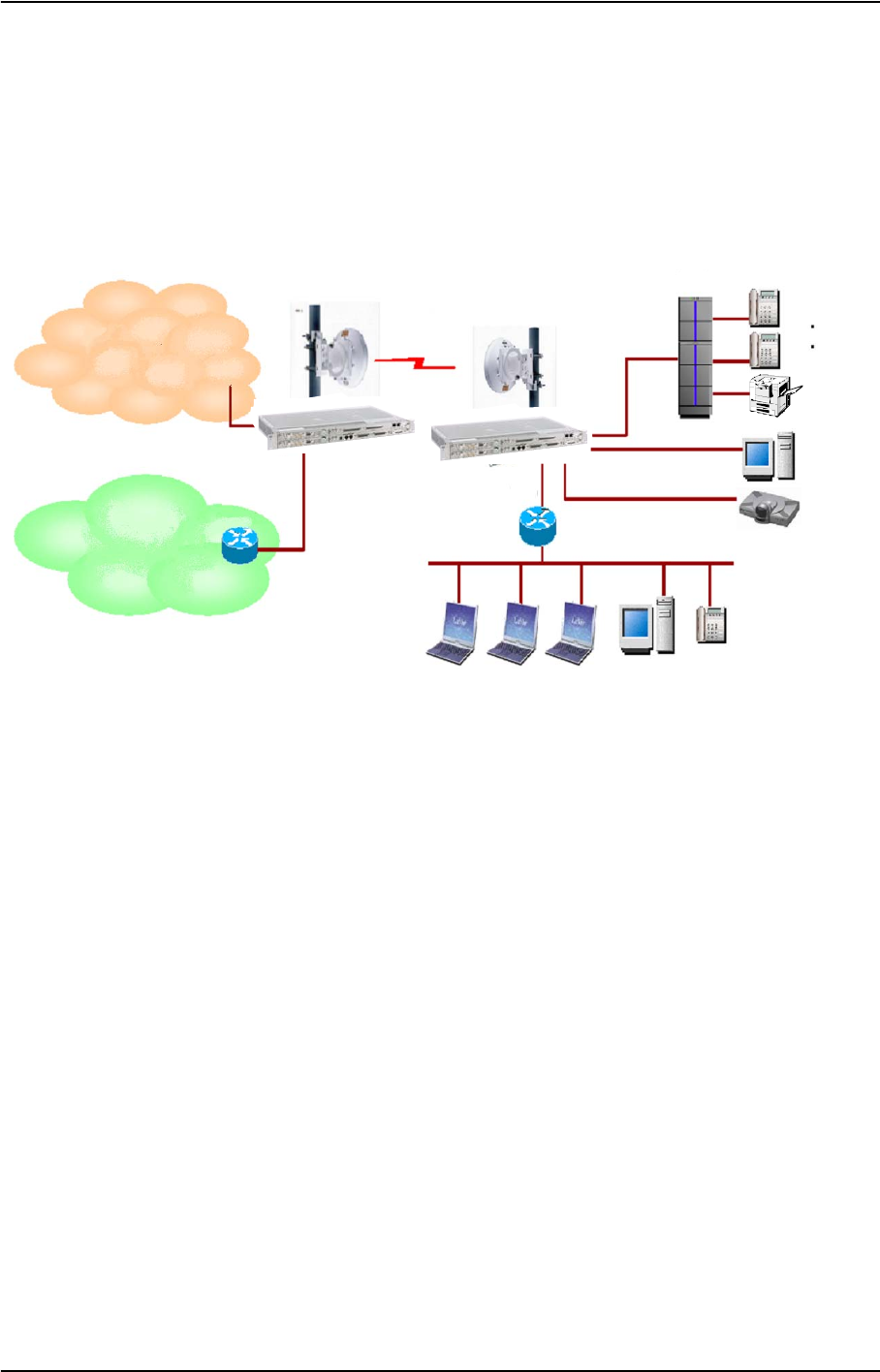
1. OUTLINE
On the NLite E, the LAN signal can be transported in Main signal domain and Auxiliary
signal domain using adaptive LAN interface module.
DATA
IP
Phone
TV
CONF
DATA
Router
LAN
Router
FAX
TEL
PABX
NLite N
10/100BASE-T(X)
10/100BASE-T(X)
PDH/SONET/ATM
Network
IP (private)
Network

ROI-S07048 NLite N
APPENDIX
MODULE INFORMATION
A-2
2. MODULE INFORMATION
(1) NWA-036103-001 2P LAN INTFC
It provides two (2) ports 10BASE-T/100BASE-TX interface and up to 16 DS1 and one (1)
WS channel (equivalent to DS1 bandwidth per channel). By easy setting, besides each port
can be used independently separated, a signal domain can be shared with two (2) LAN
ports. LAN through put maximum capacities can be set from 1.5 Mbps to 150 Mbps.
Module Features
NWA-036103-001
2P LAN INTFC
• Maximum LAN through put capacities, 1.5 Mbps - 150 Mbps
• 10BASE-T/100BASE-TX x 2 port
• Auto Negotiation / Auto MDI/MDIX, effective
• 1024 MAC Address Table, automatically learning and aging.
• Maximum frame size 1548 bytes
• Conformed to IEEE 802.3x, Pause Frame Flow Control, effective (Full Duplex)
• Half Duplex Back Pressure, effective
• Link Loss Forwarding (LLF) function
• RMON function
• CSU function
NLite N ROI-S07048
APPENDIX
APPLICATION EXAMPLE
A-3
3. APPLICATION EXAMPLE
The LAN signal transmission mode in the radio section is described as follows. Applicable
transmission mode is depending on the interface module type as listed in the following
table.
Note: √: Applicable —: Not Applicable
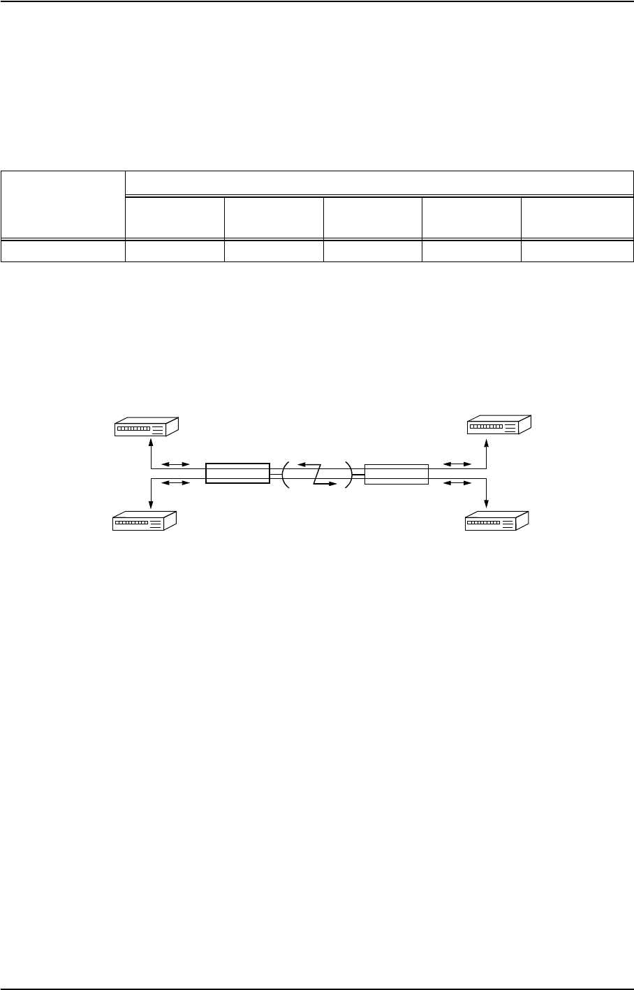
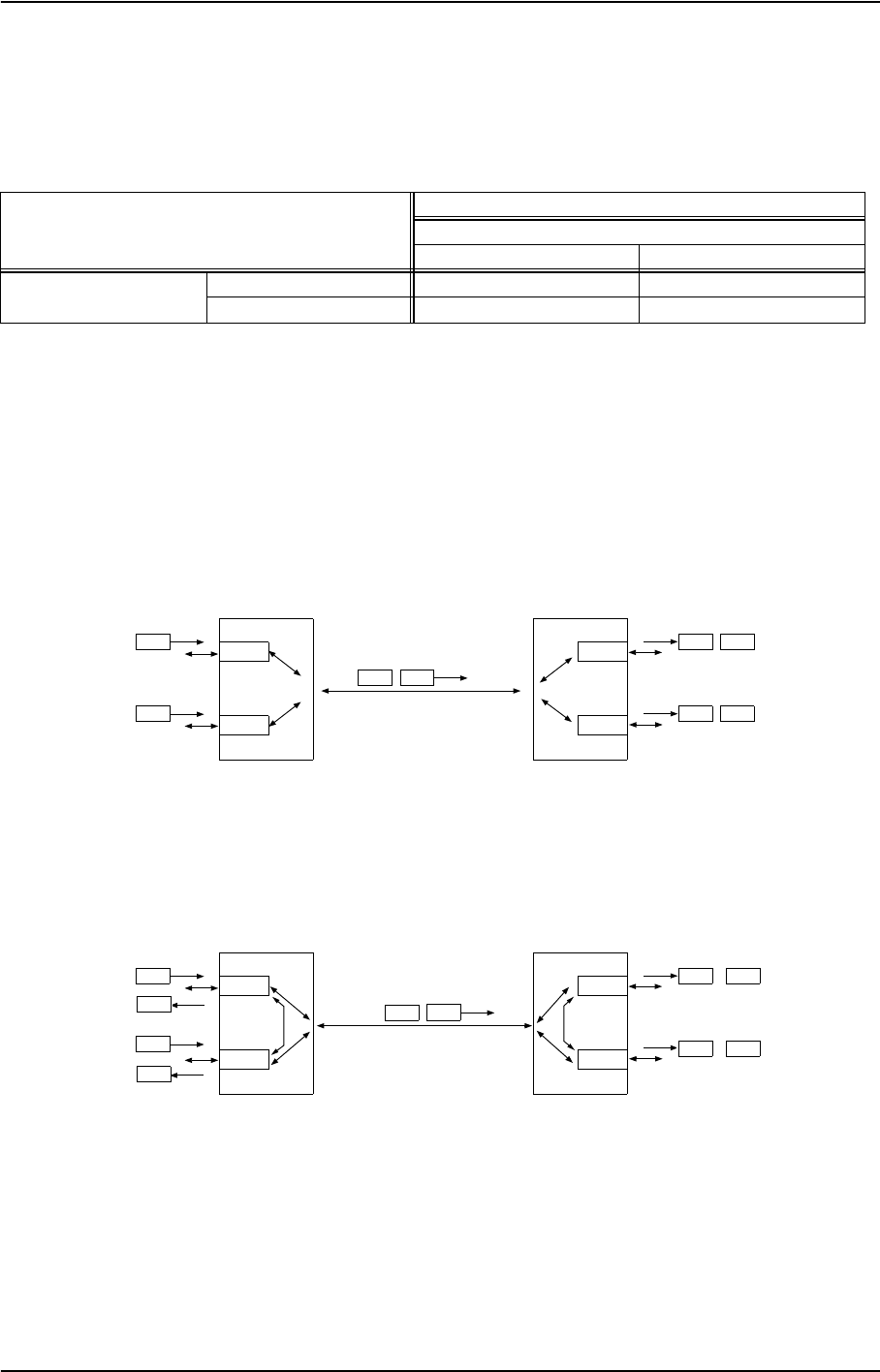
(1) Guaranteed Bandwidth Mode
Two (2) ports are completely separated and guaranteed maximum throughput for each port.
[Setup] (e.g. 2P LAN INTFC)
[Equipment Setup]→[LAN Port Usage]: P1:P2 = 1:0
P1:P2 = 1:1
Best Effort
P1 = Fixed/P2
P1 Only
P1-2 Separated
Module
Mode
(1) Guaranteed
Bandwidth (2) Switching
HUB (3) Data
Distribution (4) Best
Effort (5) DS1 Network
Connection
2P LAN INTFC √√√√ √
Customer-A
[Separated Mode]
(Port 1)
NLite N
(Port 1)
Customer-B
(Port 2)
(Port 2)
Traffics in Port1 and Port2 are completely independent.
NLite N
ROI-S07048 NLite N
APPENDIX
APPLICATION EXAMPLE
A-4
(2) Switching HUB Mode
Between distant sites are connected with switching HUB configuration.
[Setup] (e.g. 2P LAN INTFC)
[Equipment Setup]→[LAN Port Usage]: P1-2 Shared / 1 Port Only (Main)
[Provisioning]→[LAN Port Setting]→[Switching Function]: Enabled
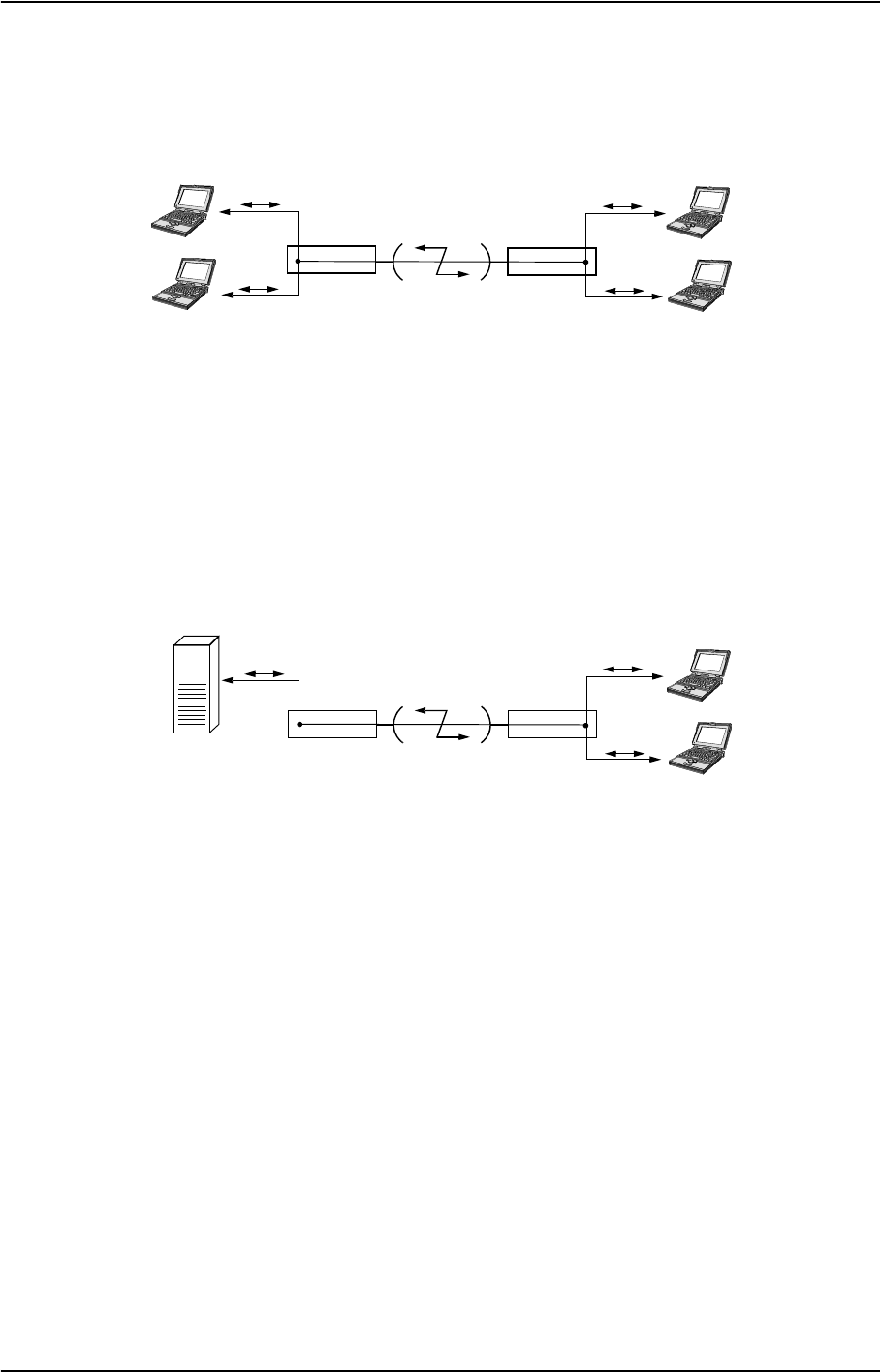
(3) DATA Distribution Mode
Make up 1 vs. 2 asymmetry network composition like below connecting data center and
terminals.
[Setup] (e.g. 2P LAN INTFC)
[Equipment Setup]→[LAN Port Usage]: P1-2 Shared / 1 Port Only (Main)
[Provisioning]→[LAN Port Setting]→[Switching Function]: Disabled
NLite N
[Shared (Switching Enabled) Mode]
(Port 2)
(Port 1)
User-3
User-4
NLite N
(Port 2)
(Port 1)
User-1
User-2
NLite N NLite N
Data Server
(Port 1)
(Port 2)
(Port 1)
(Port 2: DISABLE)
User-1
User-2
[Shared (Switching Disabled) Mode]
NLite N ROI-S07048
APPENDIX
APPLICATION EXAMPLE
A-5
(4) Best Effort Mode
Two (2) ports are separated and the signal band is shared in accordance with the traffic
quantity of each port.
It applies total transmission capacities for LAN in the radio section. It does not guaranteed
for each port.
[Setup] (e.g. 2P LAN INTFC)
[Equipment Setup]→[LAN Port Usage]: Best Effort
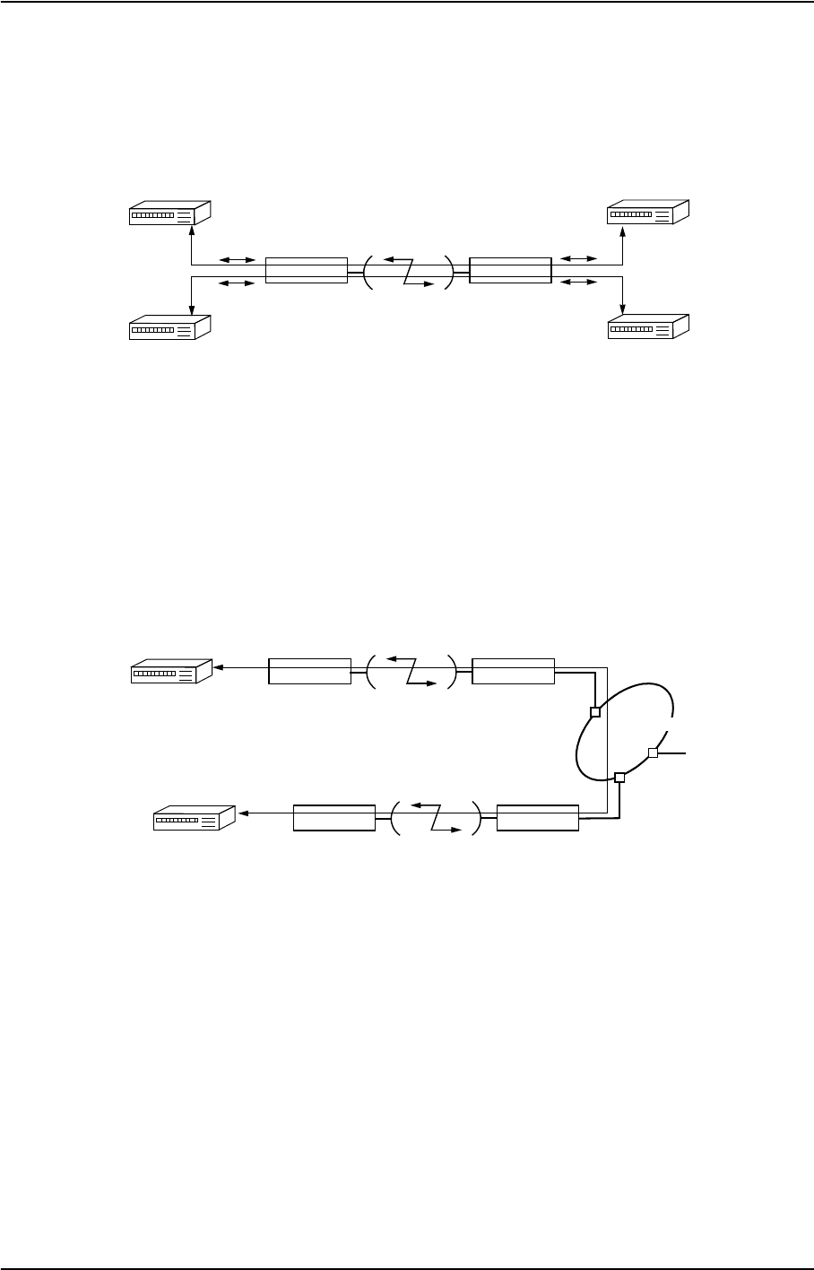
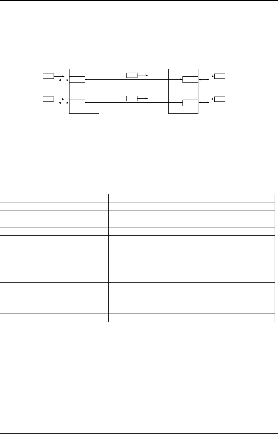
(5) DS1 Network Connection Mode
Make up LAN network via DS1 network.
[Setup] (e.g. 2P LAN INTFC)
Notes: 1. Set to LAN Enabled at the ST-A and ST-D stations, set to 1.5M at the ST-B and
ST-C stations.
2. LAN
→
DS1 (1.5 Mbps) and DS1 (1.5 Mbps)
→
LAN conversion must be
performed through the NLite N.
At ST-A / ST-D
[Equipment Setup]→[LAN Port Usage]: P1 = Fixed/P2
[Equipment Setup]→[LAN Capacity2]: P2: 1.5 Mbps
At ST-B / ST-C
[Equipment Setup]→[LAN Port Usage]: P1:P2 = 1:0
NLite N
[Best Effort Mode]
(Port 2)
(Port 1)
NLite N
(Port 2)
(Port 1)
Customer-A
Customer-B
NLite N
ST-D (LAN)
NLite N
ST-C (1.5M)
NLite N
ST-A (LAN)
NLite N
ST-B (1.5M)
Router-1
Router-2
DS1 Network

ROI-S07048 NLite N
APPENDIX
SETUP OF THE MODULE
A-6
4. SETUP OF THE MODULE
Setup of the LAN INTFC is performed with the LCT. The menu items on the LCT are as follows.
Main Menu
Equipment Setup
LAN Port Usage 4.1
LAN Capacity 4.2
Provisioning
Switching Function 4.3
Port Usage 4.5
Speed & Duplex 4.6
Flow Control 4.7
Collision Report 4.8
(Description)
LAN Port Setting
Link Loss Forwarding 4.9
1.5M Framing 4.4

NLite N ROI-S07048
APPENDIX
SETUP OF THE MODULE
A-7
4.1 Setup of LAN Mode (LAN Port Usage)
It sets Performing the setup of signal domain where LAN signal is multiplexed and multiplex
mode of it. The LAN signal can be multiplexed into the DS1 channel domain or SC/WS
channels domain.
4.1.1 Multiplexing Signal
(1) 2P LAN INTFC
a. Main Signal
The transmission bandwidth is selected from 1.5 Mbps to 150 Mbps. The setup of the
transmission bandwidth of the LAN signal is depending on the selection of the LAN Port
Usage.
b. Wayside Signal (WS)
The transmission bandwidth is 1.5 Mbps. Depending on the selection of LAN signal
capacity, WS (DS1) channels can not be of use.
c. Service Channel Signal (SC)
The transmission bandwidth is selected from 64 kbps, 128 kbps and 256 kbps. Depending
on the LAN transmission bandwidth selection, use of the V.11/RS-232C interface via SC1/
SC2/SC3/SC4 is not available.
Note: When the LAN signal is used 64 kbps bandwidth, it is assigned to domain of SC1,
when the LAN signal is used 128 kbps bandwidth, it is assigned to domains of
SC1 and SC2 or when the LAN signal is used 256 kbps bandwidth, it is assigned
to domains of SC1 to SC4.
ROI-S07048 NLite N
APPENDIX
SETUP OF THE MODULE
A-8
4.1.2 Multiplexing Mode
There are two modes of LAN Port usage; plural ports share signal domain in a radio section
(Shared Mode) and independently separated domain is secured for each port (Separated Mode).
√: Available, ⎯: Unavailable
Note: Shared/switching mode is included in the Shared setting.
(1) Shared Mode
Plural ports share signal domain in a radio section.
• P1-2 Shared
(2) Switching Mode
It is permitted that the signals pass through between local ports. When the shared mode is
setup, it is recommended that using switching mode together.
Local Equipment Setting
Opposite Equipment Setting
Terminal
Separated Shared
Terminal Separated √⎯
Shared ⎯√
PORT2
PORT1
AB
A B
A B
PORT2
PORT1
B
A
ST-B
ST-A
PORT2
PORT1 A
PORT2
PORT1
B
A
ST-B
ST-A
AB
B
A
B
AB
NLite N ROI-S07048
APPENDIX
SETUP OF THE MODULE
A-9
(3) Separated Mode
It is secured signal domain for each independent port.
• P1:P2 = 1:0, P1:P2 = 1:1, Best Effort, P1 = Fixed/P2, P1 Only, P1-2 Separated
4.1.3 Setup of LAN Port Usage
[LAN Port Usage Setup]
[Equipment Setup]→[LAN Port Usage]
(1) 2P LAN INTFC
No. Setup Description
1P1:P2 = 1:0 Bandwidth ratio between Port1 and Port2 is 1:0.
2P1:P2 = 1:1 Bandwidth ratio between Port1 and Port2 is 1:1.
3Best Effort Bandwidth ratio between Port1 and Port2 is best effort.
4P1 = Fixed/P2 Port 1 (P1) is fixed bandwidth; P2 is valuable bandwidth.
5P1-2 Shared/1Port Only (Main) Selecting when only one (1) port is used or bandwidth is shared in port1
and port2. The LAN signal is transmitted in the Main signal domain.
6P1 Only (Main) Selecting when only port1 is used. The LAN signal is transmitted in the
Main signal domain.
7P1-2 Separated (Main) Selecting when each port is used independently separated. The LAN
signal is transmitted in the Main signal domain.
8P1-2 Separated (Main + WS) Selecting when each port is used independently separated. The LAN
signal is transmitted in the Main and WS signal domain.
9P1-2 Separated (Main + SC) Selecting when each port is used independently separated. The LAN
signal is transmitted in the Main and SC signal domain.
10 Not Used The LAN transmission is not applied.
PORT2
PORT1
B
A
PORT2
PORT1
B
A
ST-B
ST-A
A
B
ROI-S07048 NLite N
APPENDIX
SETUP OF THE MODULE
A-10
4.2 Setup of LAN Signal Bandwidth (LAN Capacity)
Setting of bandwidth for the LAN signal transmission.
Settable bandwidth varies depending on the Transmission Capacity selection and LAN Port
Usage setup.
Selectable bandwidth and shared signal domain of the LAN signal are given in following tables.
The codes are used for System Configuration and Channel Assignment in the table, refer in
following Table a. and Table b.
a. System Configuration Setup Code
b. Channel Assignment Code
Note: “L”, “L1” and “L2”, italic and bold characters in Setup of LAN Capacity tables, can select
1.5M Framing function.
4.2.1 Setup of LAN Capacity
[LAN Capacity Setup]
[Equipment Setup]
→
[LAN Capacity]
Code LAN Port Usage
[A-1] P1-2 Shared/1Port Only (Main)
[A-2] P1:P2 = 1:0
P1:P2 = 1:1
Best Effort
P1 = Fixed/P2
P1 Only (Main)
P1-2 Separated (Main)
[A-3] P1-2 Separated (Main + WS)
[A-4] P1-2 Separated (Main + SC)
Code Description
DS1 1.544 Mbps (DS1) Data
L1 LAN Port1
L2 LAN Port2
L* LAN (P1:P2 = 1:0, P1:P2 = 1:1, Best Effort)
L LAN (Shared)
S V.11/RS-232C Data
- Not Assignable
NLite N ROI-S07048
APPENDIX
SETUP OF THE MODULE
A-11
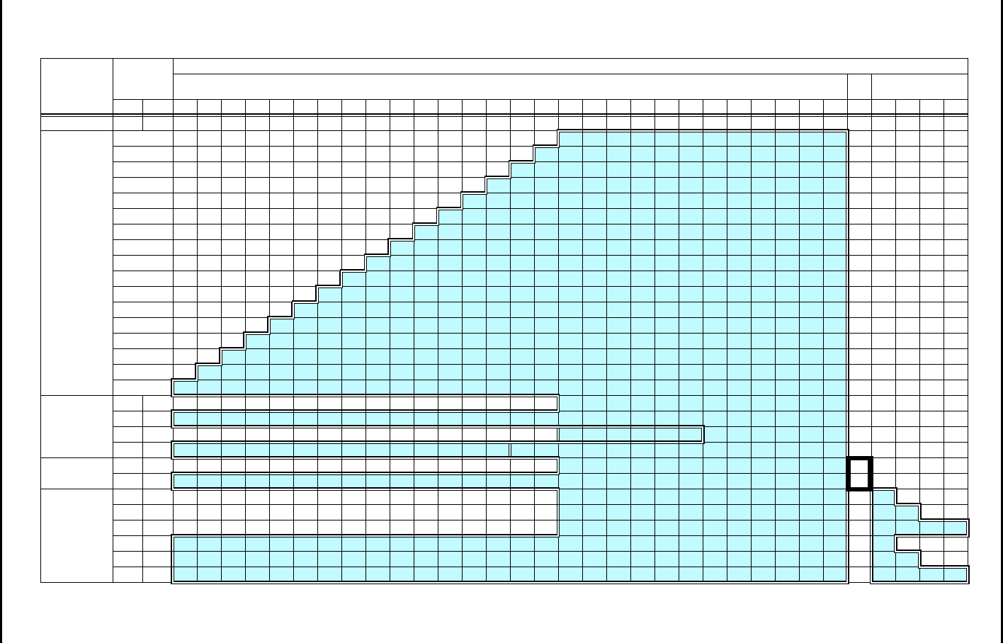
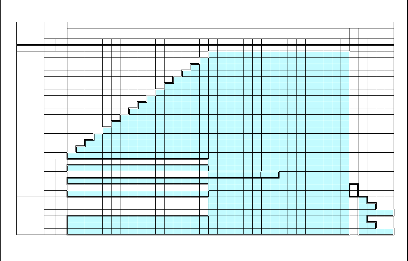
(1) 2P LAN INTFC
Note: “L2”: Highlighted in a box: can select 1.5M Framing function.
• 28 × DS1/64 QAM (Transmission Capacity : 42 Mbps)
System
Configuration LAN
Capacity
[bps]
Channel Assignment
Main Traffic WS SC
Port1Port21 2 3 4 5 6 7 8 9 10111213141516171819202122232425262728 1 1 2 3 4
Not Used - - DS1 DS1 DS1 DS1 DS1 DS1 DS1 DS1 DS1 DS1 DS1 DS1 DS1 DS1 DS1 DS1 / / / / / / / / / / / / DS1 S S S S
A-1
[Shared Main]
18M DS1 DS1 DS1 DS1 DS1 DS1 DS1 DS1 DS1 DS1 DS1 DS1 DS1 DS1 DS1 DS1 LLLLLLLLLLLLDS1SSSS
19.5M DS1 DS1 DS1 DS1 DS1 DS1 DS1 DS1 DS1 DS1 DS1 DS1 DS1 DS1 DS1 L L L L L L L L L L L L LDS1SSSS
21M DS1 DS1 DS1 DS1 DS1 DS1 DS1 DS1 DS1 DS1 DS1 DS1 DS1 DS1 LLLLLLLLLLLLLLDS1SSSS
22.5M DS1 DS1 DS1 DS1 DS1 DS1 DS1 DS1 DS1 DS1 DS1 DS1 DS1 LLLLLLLLLLLLLLLDS1SSSS
24M DS1 DS1 DS1 DS1 DS1 DS1 DS1 DS1 DS1 DS1 DS1 DS1 LLLLLLLLLLLLLLLLDS1SSSS
25.5M DS1 DS1 DS1 DS1 DS1 DS1 DS1 DS1 DS1 DS1 DS1 LLLLLLLLLLLLLLLLLDS1SSSS
27M DS1 DS1 DS1 DS1 DS1 DS1 DS1 DS1 DS1 DS1 LLLLLLLLLLLLLLLLLLDS1SSSS
28.5M DS1 DS1 DS1 DS1 DS1 DS1 DS1 DS1 DS1 LLLLLLLLLLLLLLLLLLLDS1SSSS
30M DS1 DS1 DS1 DS1 DS1 DS1 DS1 DS1 LLLLLLLLLLLLLLLLLLLLDS1SSSS
31.5M DS1 DS1 DS1 DS1 DS1 DS1 DS1 LLLLLLLLLLLLLLLLLLLLLDS1SSSS
33M DS1 DS1 DS1 DS1 DS1 DS1 LLLLLLLLLLLLLLLLLLLLLLDS1SSSS
34.5M DS1 DS1 DS1 DS1 DS1 LLLLLLLLLLLLLLLLLLLLLLLDS1SSSS
36M DS1 DS1 DS1 DS1 LLLLLLLLLLLLLLLLLLLLLLLLDS1SSSS
37.5M DS1 DS1 DS1 LLLLLLLLLLLLLLLLLLLLLLLLLDS1SSSS
39M DS1 DS1 LLLLLLLLLLLLLLLLLLLLLLLLLLDS1SSSS
40.5M DS1 LLLLLLLLLLLLLLLLLLLLLLLLLLLDS1SSSS
42M LLLLLLLLLLLLLLLLLLLLLLLLLLLLDS1SSSS
A-2
[Main+Main]
18M - DS1 DS1 DS1 DS1 DS1 DS1 DS1 DS1 DS1 DS1 DS1 DS1 DS1 DS1 DS1 DS1 L1 L1 L1 L1 L1 L1 L1 L1 L1 L1 L1 L1 DS1 S S S S
42M - L1 L1 L1 L1 L1 L1 L1 L1 L1 L1 L1 L1 L1 L1 L1 L1 L1 L1 L1 L1 L1 L1 L1 L1 L1 L1 L1 L1 DS1 S S S S
9M 9M DS1 DS1 DS1 DS1 DS1 DS1 DS1 DS1 DS1 DS1 DS1 DS1 DS1 DS1 DS1 DS1 L2 L2 L2 L2 L2 L2 L1 L1 L1 L1 L1 L1 DS1 S S S S
21M 21M L2 L2 L2 L2 L2 L2 L2 L2 L2 L2 L2 L2 L2 L2 L1 L1 L1 L1 L1 L1 L1 L1 L1 L1 L1 L1 L1 L1 DS1 S S S S
A-3 [Main+WS] 18M 1.5M DS1 DS1 DS1 DS1 DS1 DS1 DS1 DS1 DS1 DS1 DS1 DS1 DS1 DS1 DS1 DS1 L1 L1 L1 L1 L1 L1 L1 L1 L1 L1 L1 L1 L2 SSSS
42M 1.5M L1 L1 L1 L1 L1 L1 L1 L1 L1 L1 L1 L1 L1 L1 L1 L1 L1 L1 L1 L1 L1 L1 L1 L1 L1 L1 L1 L1 L2 SSSS
A-4
[Main+SC]
18M 64K DS1 DS1 DS1 DS1 DS1 DS1 DS1 DS1 DS1 DS1 DS1 DS1 DS1 DS1 DS1 DS1 L1 L1 L1 L1 L1 L1 L1 L1 L1 L1 L1 L1 DS1 L2 S S S
18M 128K DS1 DS1 DS1 DS1 DS1 DS1 DS1 DS1 DS1 DS1 DS1 DS1 DS1 DS1 DS1 DS1 L1 L1 L1 L1 L1 L1 L1 L1 L1 L1 L1 L1 DS1 L2 L2 S S
18M 256K DS1 DS1 DS1 DS1 DS1 DS1 DS1 DS1 DS1 DS1 DS1 DS1 DS1 DS1 DS1 DS1 L1 L1 L1 L1 L1 L1 L1 L1 L1 L1 L1 L1 DS1 L2 L2 L2 L2
42M 64K L1 L1 L1 L1 L1 L1 L1 L1 L1 L1 L1 L1 L1 L1 L1 L1 L1 L1 L1 L1 L1 L1 L1 L1 L1 L1 L1 L1 DS1 L2 S S S
42M 128K L1 L1 L1 L1 L1 L1 L1 L1 L1 L1 L1 L1 L1 L1 L1 L1 L1 L1 L1 L1 L1 L1 L1 L1 L1 L1 L1 L1 DS1 L2 L2 S S
42M 256K L1 L1 L1 L1 L1 L1 L1 L1 L1 L1 L1 L1 L1 L1 L1 L1 L1 L1 L1 L1 L1 L1 L1 L1 L1 L1 L1 L1 DS1 L2 L2 L2 L2
ROI-S07048 NLite N
APPENDIX
SETUP OF THE MODULE
A-12
Note: “L2”: Highlighted in a box: can select 1.5M Framing function.
• 32 × DS1/QPSK (Transmission Capacity : 48 Mbps)
System
Configuration LAN
Capacity
[bps]
Channel Assignment
Main Traffic WS SC
Port1Port2123456789101112131415161718192021222324252627282930313211234
Not Used - -DS1DS1DS1DS1DS1DS1DS1DS1DS1DS1DS1DS1DS1DS1DS1DS1////////////////DS1SSSS
A-1
[Shared Main]
24M DS1 DS1 DS1 DS1 DS1 DS1 DS1 DS1 DS1 DS1 DS1 DS1 DS1 DS1 DS1 DS1 LLLLLLLLLLLLLLLLDS1SSSS
25.5M DS1 DS1 DS1 DS1 DS1 DS1 DS1 DS1 DS1 DS1 DS1 DS1 DS1 DS1 DS1 LLLLLLLLLLLLLLLLLDS1SSSS
27M DS1 DS1 DS1 DS1 DS1 DS1 DS1 DS1 DS1 DS1 DS1 DS1 DS1 DS1 LLLLLLLLLLLLLLLLLLDS1SSSS
28.5M DS1 DS1 DS1 DS1 DS1 DS1 DS1 DS1 DS1 DS1 DS1 DS1 DS1 LLLLLLLLLLLLLLLLLLLDS1SSSS
30M DS1 DS1 DS1 DS1 DS1 DS1 DS1 DS1 DS1 DS1 DS1 DS1 LLLLLLLLLLLLLLLLLLLLDS1SSSS
31.5M DS1 DS1 DS1 DS1 DS1 DS1 DS1 DS1 DS1 DS1 DS1 LLLLLLLLLLLLLLLLLLLLLDS1SSSS
33M DS1 DS1 DS1 DS1 DS1 DS1 DS1 DS1 DS1 DS1 LLLLLLLLLLLLLLLLLLLLLLDS1SSSS
34.5M DS1 DS1 DS1 DS1 DS1 DS1 DS1 DS1 DS1 LLLLLLLLLLLLLLLLLLLLLLLDS1SSSS
36M DS1 DS1 DS1 DS1 DS1 DS1 DS1 DS1 LLLLLLLLLLLLLLLLLLLLLLLLDS1SSSS
37.5M DS1 DS1 DS1 DS1 DS1 DS1 DS1 LLLLLLLLLLLLLLLLLLLLLLLLLDS1SSSS
39M DS1 DS1 DS1 DS1 DS1 DS1 LLLLLLLLLLLLLLLLLLLLLLLLLLDS1SSSS
40.5M DS1 DS1 DS1 DS1 DS1 LLLLLLLLLLLLLLLLLLLLLLLLLLLDS1SSSS
42M DS1 DS1 DS1 DS1 LLLLLLLLLLLLLLLLLLLLLLLLLLLLDS1SSSS
43.5M DS1 DS1 DS1 LLLLLLLLLLLLLLLLLLLLLLLLLLLLLDS1SSSS
45M DS1 DS1 LLLLLLLLLLLLLLLLLLLLLLLLLLLLLLDS1SSSS
46.5M DS1 LLLLLLLLLLLLLLLLLLLLLLLLLLLLLLLDS1SSSS
48M LLLLLLLLLLLLLLLLLLLLLLLLLLLLLLLLDS1SSSS
A-2
[Main+Main]
24M - DS1 DS1 DS1 DS1 DS1 DS1 DS1 DS1 DS1 DS1 DS1 DS1 DS1 DS1 DS1 DS1 L1 L1 L1 L1 L1 L1 L1 L1 L1 L1 L1 L1 L1 L1 L1 L1DS1SSSS
48M - L1 L1 L1 L1 L1 L1 L1 L1 L1 L1 L1 L1 L1 L1 L1 L1 L1 L1 L1 L1 L1 L1 L1 L1 L1 L1 L1 L1 L1 L1 L1 L1DS1SSSS
12M 12M DS1 DS1 DS1 DS1 DS1 DS1 DS1 DS1 DS1 DS1 DS1 DS1 DS1 DS1 DS1 DS1 L2 L2 L2 L2 L2 L2 L2 L2 L1 L1 L1 L1 L1 L1 L1 L1DS1SSSS
24M 24M L2 L2 L2 L2 L2 L2 L2 L2 L2 L2 L2 L2 L2 L2 L2 L2 L1 L1 L1 L1 L1 L1 L1 L1 L1 L1 L1 L1 L1 L1 L1 L1DS1SSSS
A-3
[Main+WS]
24M 1.5M DS1 DS1 DS1 DS1 DS1 DS1 DS1 DS1 DS1 DS1 DS1 DS1 DS1 DS1 DS1 DS1 L1 L1 L1 L1 L1 L1 L1 L1 L1 L1 L1 L1 L1 L1 L1 L1 L2 SSSS
48M 1.5M L1 L1 L1 L1 L1 L1 L1 L1 L1 L1 L1 L1 L1 L1 L1 L1 L1 L1 L1 L1 L1 L1 L1 L1 L1 L1 L1 L1 L1 L1 L1 L1 L2 SSSS
A-4
[Main+SC]
24M 64K DS1 DS1 DS1 DS1 DS1 DS1 DS1 DS1 DS1 DS1 DS1 DS1 DS1 DS1 DS1 DS1 L1 L1 L1 L1 L1 L1 L1 L1 L1 L1 L1 L1 L1 L1 L1 L1 DS1 L2SSS
24M 128K DS1 DS1 DS1 DS1 DS1 DS1 DS1 DS1 DS1 DS1 DS1 DS1 DS1 DS1 DS1 DS1 L1 L1 L1 L1 L1 L1 L1 L1 L1 L1 L1 L1 L1 L1 L1 L1 DS1 L2 L2 S S
24M 256K DS1 DS1 DS1 DS1 DS1 DS1 DS1 DS1 DS1 DS1 DS1 DS1 DS1 DS1 DS1 DS1 L1 L1 L1 L1 L1 L1 L1 L1 L1 L1 L1 L1 L1 L1 L1 L1 DS1 L2 L2 L2 L2
48M 64K L1 L1 L1 L1 L1 L1 L1 L1 L1 L1 L1 L1 L1 L1 L1 L1 L1 L1 L1 L1 L1 L1 L1 L1 L1 L1 L1 L1 L1 L1 L1 L1 DS1 L2SSS
48M 128K L1 L1 L1 L1 L1 L1 L1 L1 L1 L1 L1 L1 L1 L1 L1 L1 L1 L1 L1 L1 L1 L1 L1 L1 L1 L1 L1 L1 L1 L1 L1 L1 DS1 L2 L2 S S
48M 256K L1 L1 L1 L1 L1 L1 L1 L1 L1 L1 L1 L1 L1 L1 L1 L1 L1 L1 L1 L1 L1 L1 L1 L1 L1 L1 L1 L1 L1 L1 L1 L1 DS1 L2 L2 L2 L2
NLite N ROI-S07048
APPENDIX
SETUP OF THE MODULE
A-13
Note: “L2”: Highlighted in a box: can select 1.5M Framing function.
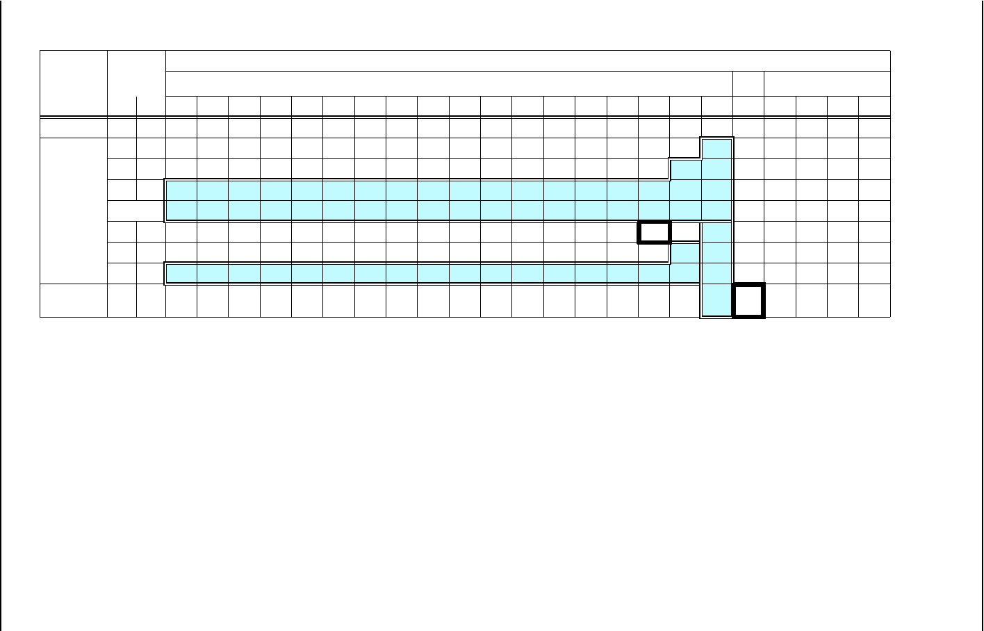
•1 × OC-3/16 QAM, 1 × OC-3/64 QAM, 1 × OC-3/128 QAM (Transmission Capacity : 150 Mbps)
System
Configuratio
n
LAN
Capacity
[bps]
Channel Assignment
Main Traffic WS SC
Port1Port21234567891011121314151626M100M 11234
Not Used --DS1DS1DS1DS1DS1DS1DS1DS1DS1DS1DS1DS1DS1DS1DS1DS1/ /DS1SSSS
A-2
[Main+Main]
100M - DS1 DS1 DS1 DS1 DS1 DS1 DS1 DS1 DS1 DS1 DS1 DS1 DS1 DS1 DS1 DS1 / L*DS1SSSS
63M 63M DS1 DS1 DS1 DS1 DS1 DS1 DS1 DS1 DS1 DS1 DS1 DS1 DS1 DS1 DS1 DS1 L* L*DS1SSSS
75M 75M L* L* L* L* L* L* L* L* L* L* L* L* L* L* L* L* L* L*DS1SSSS
150M L* L* L* L* L* L* L* L* L* L* L* L* L* L* L* L* L* L*DS1SSSS
100M 1.5M DS1 DS1 DS1 DS1 DS1 DS1 DS1 DS1 DS1 DS1 DS1 DS1 DS1 DS1 DS1 L2 /L1DS1SSSS
100M 26M DS1 DS1 DS1 DS1 DS1 DS1 DS1 DS1 DS1 DS1 DS1 DS1 DS1 DS1 DS1 DS1 L2 L1DS1SSSS
100M 50M L2 L2 L2 L2 L2 L2 L2 L2 L2 L2 L2 L2 L2 L2 L2 L2 L2 L1DS1SSSS
A-3
[Main+WS] 100M 1.5M DS1 DS1 DS1 DS1 DS1 DS1 DS1 DS1 DS1 DS1 DS1 DS1 DS1 DS1 DS1 DS1 / L1 L2 SSSS
ROI-S07048 NLite N
APPENDIX
SETUP OF THE MODULE
A-14
4.3 Setup of the Switching Mode (Switching Function)
This is switching mode setup between local ports which share domain, that is available only on
the shared mode.
[Switching Function Setup]
[Provisioning]
→
[LAN Port Setup]
→
[Switching Function]
4.4 Setup of 1.5M Framing
When the LAN bandwidth is set to 1.5 Mbps, DS1 framing corresponded to ANSI T1.403 is
available in the transmission data in the radio link.
4.5 Setup of Used/Unused Port (Port Usage)
This is the setup of the used or unused LAN port.
[Port Usage Setup]
[Provisioning]
→
[LAN Port Setup]
→
[Port Usage]
Note: When Not Used is selected, link of port is compulsorily released.
No. Setup Descriptions
1Enabled Enables data communication between local ports which share domain.
2Disabled (Default) Disables data communication between local ports which share domain.
No. Setup Descriptions
1UF (Unframed) Framing is not effected.
All 1.5 Mbps are used for LAN signal bandwidth.
2SF (ANSI T1.107) Framing is effected for Superframe frame.
3ESF (ANSI T1.107) Framing is effected for Extended Superframe frame.
No. Setup Descriptions
1Used Port is used.
2Not Used (Default) Port is not used.

NLite N ROI-S07048
APPENDIX
SETUP OF THE MODULE
A-15
4.6 Setup of Port Speed & Duplex
This is the setup of the operation mode of LAN port.
1) 10/100BASE-TX Supported port
[Speed & Duplex Setup]
[Provisioning]
→
[LAN Port Setup]
→
[Speed & Duplex]
No. Mode Descriptions
1AUTONEG (AUTO-MDI/MDIX)
Auto-Negotiation (Auto-MDI/MDIX)
(Default)
Depending on the connecting NE, the setting of 10M / 100M, Half /
Full and STRAIGHT / CROSSED are plugged in auto-sensing.
210M - HALF (MDI)
10BASE-T HALF Duplex (MDI)
For 10M Half-Duplex (MDI), set to fixed mode.
310M - FULL (MDI)
10BASE-T FULL Duplex (MDI)
For 10M Full-Duplex (MDI), set to fixed mode.
4100M - HALF (MDI)
100BASE-TX HALF Duplex (MDI)
For 100M Half-Duplex (MDI), set to fixed mode.
5100M - FULL (MDI)
100BASE-TX FULL Duplex (MDI)
For 100M Full-Duplex (MDI), set to fixed mode.
610M - HALF (MDIX)
10BASE-T HALF Duplex (MDIX)
For 10M Half-Duplex (MDIX), set to fixed mode.
710M - FULL (MDIX)
10BASE-T FULL Duplex (MDIX)
For 10M Full-Duplex (MDIX), set to fixed mode.
8100M - HALF (MDIX)
100BASE-TX HALF Duplex (MDIX)
For 100M Half-Duplex (MDIX), set to fixed mode.
9100M - FULL (MDIX)
100BASE-TX FULL Duplex (MDIX)
For 100M Full-Duplex (MDIX), set to fixed mode.

ROI-S07048 NLite N
APPENDIX
SETUP OF THE MODULE
A-16
4.6.1 Setup for External Connection
According to the setting mode of the connected equipment port, the LAN port setup is
performed. Acceptable port settings are as follows
Note: The connection of different setting mode, it may be caused inferior performance or link
loss.
4.6.2 Setup of MDI / MDIX
When the Auto Negotiation is applied, it is operated with Auto MDI or MDIX. It can be
selected MDI or MDIX by manual setting mode.
MDI : Straight Port Setting
Select MDI when the crossed cable is connected to the straight port of the
external equipment or straight cable is connected to the crossed port of the
external equipment.
MDIX : Crossed Port Setting
Select MDIX in other conditions than above MDI.
Auto MDI/MDIX
Straight or Crossed is auto-sensing to correspond to the connected equipment.
External Equipment
Auto
Negotiation 10BASE-T/
Half Duplex 10BASE-T/
Full-Duplex 100BASE-TX/
Half-Duplex 100BASE-TX /
Full-Duplex
Port Setting
Auto Negotiation
(Auto MDI/MDIX) √√⎯√⎯
10BASE-T/
Half Duplex √ √ ⎯⎯⎯
10BASE-T/
Full-Duplex ⎯⎯ √ ⎯⎯
100BASE-TX/
Half-Duplex √⎯⎯√⎯
100BASE-TX /
Full-Duplex ⎯⎯⎯⎯ √
NLite N ROI-S07048
APPENDIX
SETUP OF THE MODULE
A-17
4.7 Setup of Flow Control (Flow Control)
This is the setup of ON/OFF for the flow control function to each port.
[Flow Control]
[Provisioning]
→
[LAN Port Setup]
→
[Flow Control]
4.7.1 Flow Control
In accordance with the Half/Full-Duplex mode, following two (2) flow control modes provide in
the INTFC module.
4.8 Setup of Collision Report
In HALF-Duplex mode, it is selected that is reported or not reported about collision conditions at
each port.
[Collision Report]
[Provisioning]
→
[LAN Port Setup]
→
[Collision Report]
Note: When the flow control is applied in HALF-Duplex mode, a collision condition may be
occurred while the Back Pressure control, therefore, use of “Not Reported” mode is
recommended.
No. Setup Descriptions
1On (Default) Flow control is operated.
2Off Flow control is not operated.
No. Mode Description of Flow Control System
1Half-Duplex Back Pressure:
To prevent frame inflow, it is caused pseudo-collision by sending jam signals.
2Full-Duplex PAUSE frame Flow Control:
By sending PAUSE frame (conformed to IEEE 802.3x), request the opposite
equipment that the frame sending to be stopped/started. It is required that the
opposite equipment also has this function.
No. Setup Descriptions
1Reported Collision condition is reported.
2Not Reported (Default) Collision condition is not reported.
ROI-S07048 NLite N
APPENDIX
SETUP OF THE MODULE
A-18
4.9 Port Link Loss Forwarding (LLF) / Link Down Control
4.9.1 LAN
The function is provided for compulsorily release the local link by detecting opposite link failure.
It can be set the control that it is enabled/disabled the function for each port.
[Link loss Forwarding]
[Provisioning]
→
[LAN Port Setup]
→
[Link loss Forwarding]
Notes: 1. When LOF/High BER alarm occurs in a radio section, regardless of above setup, link is
compulsorily released.
2. When the Port Switching is set to Enabled, this function is not operated.
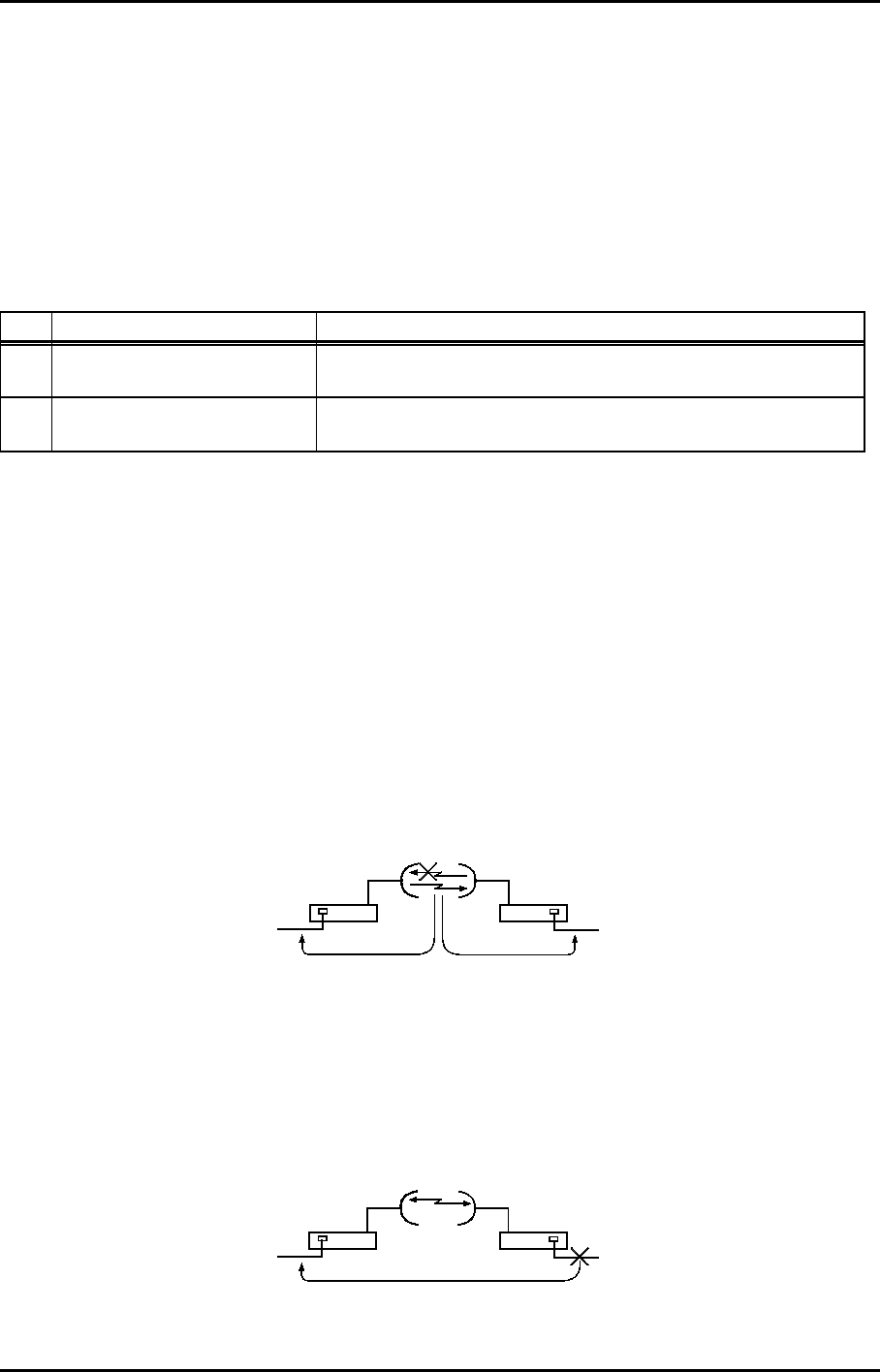
4.9.1.1 Control of Releasing Link
The function provides the control to release the link at both terminals when the radio section
failure or LAN port link failure occurs.
a. Control of Compulsorily Released Link by Radio Channel Failure
When radio section failure occurs, port link is compulsorily released for both end
terminals. This function operates regardless of setting of the Loss Forwarding function.
Note: The control is performed in accordance with the setting conditions of the AIS
Activation Condition. (Default: LOF + High BER Alarm)
b. Control of Compulsorily Released Link by the Opposite Link Failure
When the Link Loss Forwarding function is set to Enabled, the local link is compulsorily
released by detecting the link failure of the opposite station.
No. Setup Descriptions
1Enabled Enables the function to compulsorily release the local link by information
from the opposite link.
2Disabled
(Default)
Disables the function to compulsorily release the local link by information
from the opposite link.
Ethernet
[ST-B]
Radio
Ethernet
[ST-A]
(local) (opposite)
Ethernet
[ST-B]
Radio
Ethernet
[ST-A]
(local) (opposite)

NLite N ROI-S07048
APPENDIX
ALARM/STATUS INDICATION AND REPORTING
A-19
5. ALARM/STATUS INDICATION AND REPORTING
The alarm/status of the LAN interface can be observed using LCT. Link status is also observable
with LED indicators on the module front. The menu structure of LCT is as follows.
⎪
+Alarm/Status ············································ Chapter 5.2
⎪⎪
⎪+LAN Link
⎪+LAN Collision
⎪+Link Loss Forwarding (LLF)
+Link Down Control
+LLF (Any port)
+LLF (ALL port)
⎪+Speed & Duplex
⎪
+RMON (History) ············································ Chapter 5.3
⎪
+RMON(Line)(24H/15min)
+RMON(Line)(7days/day)
+RMON(DMR)(24H/15min)
+RMON(DMR)(7days/day)
ROI-S07048 NLite N
APPENDIX
ALARM/STATUS INDICATION AND REPORTING
A-20
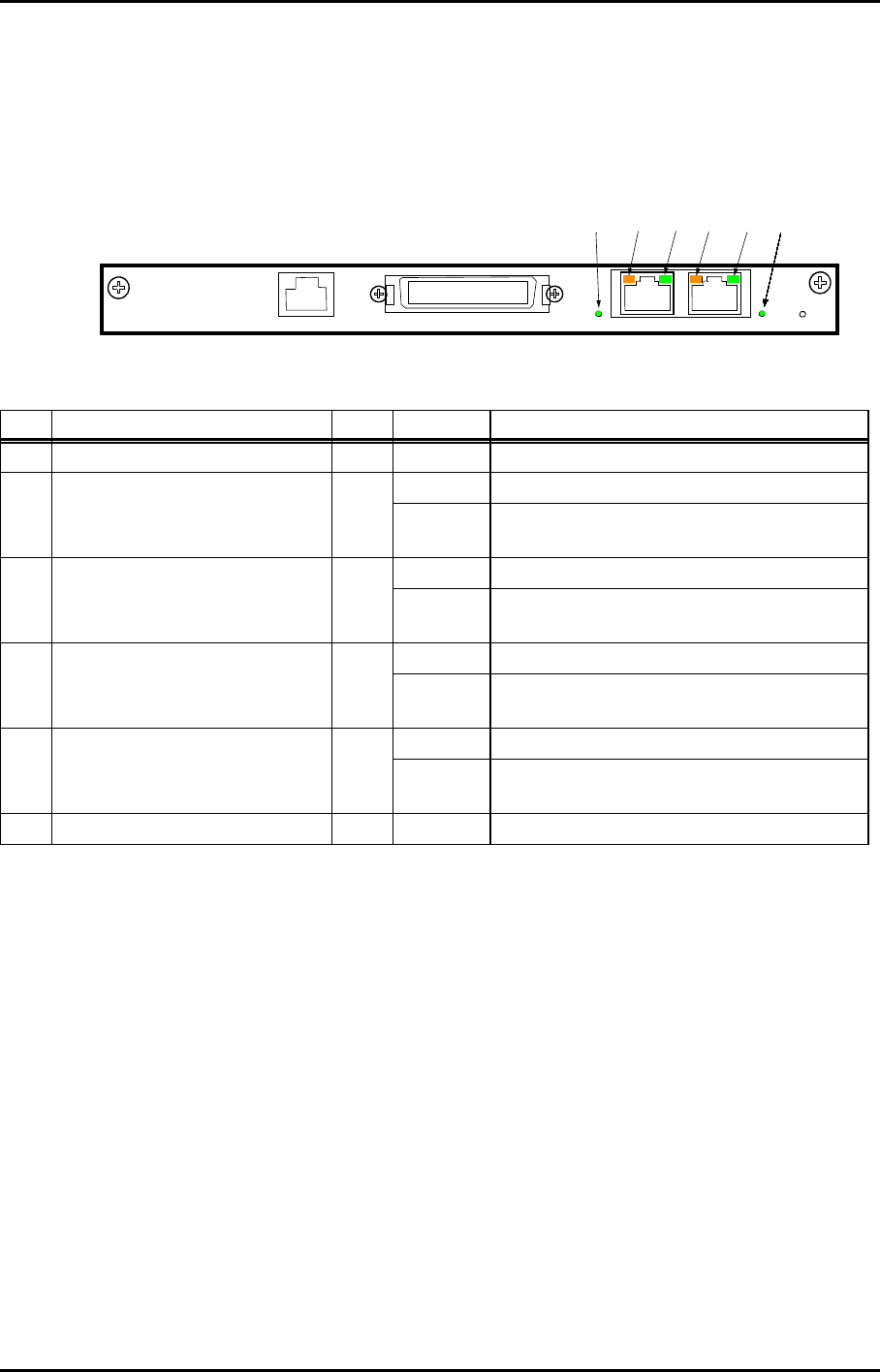
5.1 LED Indication
The following visual indications with LEDs are provided on the module front.
Name of LED Color Indication Descriptions
(a) Port1 100M green lighting When Port 1 is linked in 100M mode.
(b) Port1 Collision / Full Duplex amber lighting When Port 1 is linked in Full-Duplex mode.
blinking When Port 1 is linked in Half-Duplex mode and
collision condition occurs.
(c) Port1 LINK / TX/RX Activity green lighting When Port 1 is linked.
blinking When Port 1 is linked and data is sending and
receiving.
(d) Port2 Collision / Full Duplex amber lighting When Port 2 is linked in Full-Duplex mode.
blinking When Port 2 is linked in Half-Duplex mode and
collision condition occurs.
(e) Port2 LINK / TX/RX Activity green lighting When Port 2 is linked.
blinking When Port 2 is linked and data is sending and
receiving.
(f) Port2 100M green lighting When Port 2 is linked in 100M mode.
(2) 2P LAN INTFC
100M PORT 1 PORT 2 100M
ALM
DS1 IN/OUT
WS IN/OUT
Ns
(a) (b) (c) (d) (e) (f)

NLite N ROI-S07048
APPENDIX
ALARM/STATUS INDICATION AND REPORTING
A-21
5.2 Alarm/Status Report
The following alarm/status are reported to the equipment.
Note: *: Refer to Chapter 4.9 Link Loss Forwarding for compulsive release of link.
No. Alarm/Status Condition Message Descriptions
1Port( ) Link Alarm Link Reporting about link condition in Port( ).
Surveillance object as alarm item of the MDP.
Note: It does not reported when Port
Usage is set to Not Used.
Alarm
2Port( ) Collision Status Normal Reporting about occurrence of collision in
Port( ).
By setting of Port Collision Report, the
selection of either Report/Not Report is
applicable.
Collision
3Port( ) Speed & Duplex Status 10M - Half (MDI) Reporting established link mode of Port( ).
Notes:1. If link failure occurs in Auto-
Negotiation mode, it is sets as 10M-
Half (MDIX) or 10M-Half (MDI).
100M - Half (MDI)
10M - Full (MDI)
100M - Full (MDI)
10M - Half (MDIX)
100M - Half (MDIX)
10M - Full (MDIX)
100M - Full (MDIX)
4Port( ) Link Loss Forwarding Status Normal Reporting situation of the compulsive release
of link in Port( ).*
Supporting this when Radio +LLF (Any port/
ALL port) is selected at Link Down Control
setting
Under Execution

ROI-S07048 NLite N
APPENDIX
ALARM/STATUS INDICATION AND REPORTING
A-22
5.3 Remote Network Monitoring (RMON)
Observing passing LAN signal through each LAN port, it provides RMON functions to itemize
statistics of total number of transmitting frames, receiving frames and error frames. The statistic
informations are indicated per 15 minutes for 24 hours and per 1 day for 7 days.
Note: √; Objective Item, —; Out of Objective Item
From No.1 to No.3 and No.5 to No.7 operate within 64 to 1536 bytes.
From No.10 ~ No.15 include error frame as object.
No.16 does not include error frame as object.
From No.18 to No.20 the operate within 64 to 1916 bytes.
No. Statistics Item Objective Description
Line DMR
1Rx Unicast √√Total number of received frame addressed to unicast.
2Rx Broadcast √√Total number of received frame addressed to broadcast.
3Rx Multicast √√Total number of received frame addressed to multicast.
4Rx Pause √√Total number of received frame of PAUSE.
5Rx CRC Error √√Total number of received frame of detected FCS error.
6Rx Alignment Error √—Total number of received frame of alignment error.
7Rx Symbol Error √—Total number of received frame of symbol error.
8Rx Undersize √√Total number of received frame excluded erred frame for less than
63 bytes frame length.
9Rx Fragments √√Total number of received frame included erred frame for less than
63 bytes frame length.
10 Rx Pkets 64 √√Total number of received frame of 63 bytes frame length.
11 Rx Pkets 65 to 127 √√Total number of received frame from 65 bytes to 127 bytes frame
length.
12 Rx Pkets 128 to 255 √√Total number of received frame from 128 bytes to 255 bytes frame
length.
13 Rx Pkets 256 to 511 √√Total number of received frame from 256 bytes to 511 bytes frame
length.
14 Rx Pkets 512 to 1023 √√Total number of received frame from 512 bytes to 1023 bytes frame
length.
15 Rx Pkets 1024 to 1536 √√Total number of received frame from 1024 bytes to 1536 bytes
frame length.
16 Rx Pkets 1537 to Max Size √√Total number of received frame excluded erred frame from 1537
bytes to 1916 bytes frame length.
17 Rx Jabbers √√Total number of received frame included erred frame exceeding
1537 bytes frame length.
18 Tx Unicast √√Total number of transmitted frame addressed to unicast.
19 Tx Broadcast √√Total number of transmitted frame addressed to broadcast.
20 Tx Multicast √√Total number of transmitted frame addressed to multicast.
21 Tx Pause √√Total number of transmitted frame of PAUSE.
22 Tx Total Collision √—Total number of occurred collision.

NLite N ROI-S07048
APPENDIX
MAINTENANCE/CONTROL
A-23
6. MAINTENANCE/CONTROL
6.1 Remote Reset (LAN Device Reset)
It can be performed Reset control for LAN Port.
[LAN Device Reset Control]
[Maintenance]
→
[Maintenance1]
Note: *: Not performed when in normal operation.
Link failure may be occurred when reset control is performed.
⎪
+Maintenance
⎪
+Maintenance1
⎪⎪
⎪+LAN Device Reset ············································ Chapter 6.1
No. Item Descriptions
1INTFC(1) Port* Perform reset control for LAN Port.

ROI-S07048 NLite N
APPENDIX
MAINTENANCE/CONTROL
A-24
E
This page is intentionally left blank.