NEC of America 58155N NLite N 5.8 GHz Digital Microwave Radio User Manual inst
NEC Corporation of America NLite N 5.8 GHz Digital Microwave Radio inst
Contents
User Manual - Part III

ROI-S07045-051E CONTENTS
July, 2009
CL-1
NLite N
6-38 GHz DIGITAL RADIO SYSTEM
Section III INSTALLATION AND INITIAL LINE UP
CONTENTS
TITLE PAGE
1 GENERAL ••••••••••••••••••••••••••••••••••••••••••••••••••••••••••••• 1-1
2 INSTALLATION •••••••••••••••••••••••••••••••••••••••••••••••••••••• 2-1
2.1 Packages••••••••••••••••••••••••••••••••••••••••••••••••••••••••••• 2-2
2.2 Unpacking of MDP and TRP •••••••••••••••••••••••••••••••••• 2-9
2.3 MDP Mounting••••••••••••••••••••••••••••••••••••••••••••••••••• 2-13
2.4 DC-DC CONV UNIT Mounting (Optional) ••••••••••••••••• 2-16
2.5 TRP Mounting ••••••••••••••••••••••••••••••••••••••••••••••••••• 2-17
2.5.1 Mounting•••••••••••••••••••••••••••••••••••••••••••••••••••••••••• 2-19
2.5.2 TRP Wall Mounting••••••••••••••••••••••••••••••••••••••••••••• 2-70
2.5.3 TRP Rack Mounting•••••••••••••••••••••••••••••••••••••••••••• 2-74
2.6 Feeder Connection••••••••••••••••••••••••••••••••••••••••••••• 2-76
2.7 Cable Termination•••••••••••••••••••••••••••••••••••••••••••••• 2-94
2.8 Wiring and Forming•••••••••••••••••••••••••••••••••••••••••• 2-127
2.9 Frame Grounding••••••••••••••••••••••••••••••••••••••••••••• 2-131
2.10 Waterproof Protection••••••••••••••••••••••••••••••••••••••• 2-134
3 INITIAL LINE UP••••••••••••••••••••••••••••••••••••••••••••••••••••• 3-1
3.1 Start-up••••••••••••••••••••••••••••••••••••••••••••••••••••••••••••• 3-2
3.2 Shut-down••••••••••••••••••••••••••••••••••••••••••••••••••••••••• 3-8
3.3 Initial Setting•••••••••••••••••••••••••••••••••••••••••••••••••••••• 3-9
3.3.1 Equipment Setup ••••••••••••••••••••••••••••••••••••••••••••••• 3-10
3.3.2 Provisioning ••••••••••••••••••••••••••••••••••••••••••••••••••••• 3-11
3.4 Antenna Orientation ••••••••••••••••••••••••••••••••••••••••••• 3-12
3.5 Lineup Test••••••••••••••••••••••••••••••••••••••••••••••••••••••• 3-26
3.6 TRP Mounting/Demounting (ALL INDOOR TRP)••••••• 3-33
3.6.1 TRP Demounting (ALL INDOOR TRP)••••••••••••••••••••• 3-41
3.7 System Expansion (ALL INDOOR TRP) •••••••••••••••••• 3-43
CONTENTS ROI-S07045
CL-2
2 pages
(This page is intentionally left blank.)

ROI-S07045 GENERAL
1-1
1. GENERAL
This section provides installation and initial line up information on the
NLite N used for 6-38 GHz microwave radio system.
GENERAL ROI-S07045
1-2
2 pages
(This page is intentionally left blank.)
ROI-S07045 INSTALLATION
2-1
2. INSTALLATION
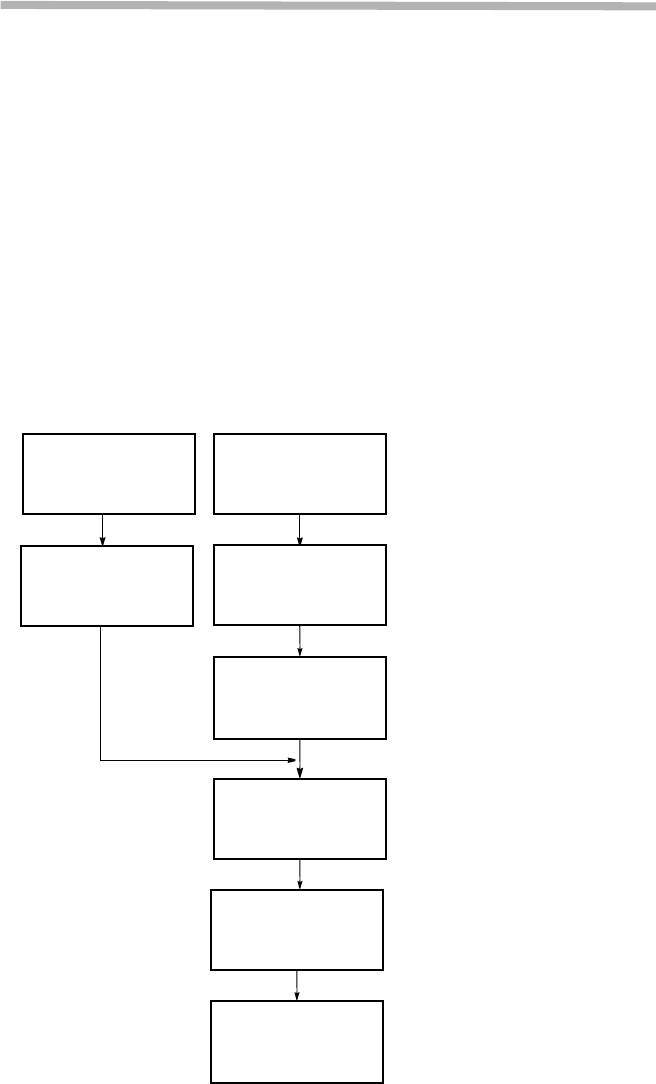
The standard installation is summarized in this section. Included herein is
information on typical installation work flow and guides for MDP
installation, TRP installation, Antenna (ANT) installation, waveguide
connection and coaxial cable connections. The installation flow diagram is
shown below.
This product is a part of radio link system, and is intended to be connected
with a external antenna.
This product will be installed and operated by professional.
After installation, the professional person shall make sure that the system
shall comply with the relevant limits for general public exposure specified
as basic restrictions or reference levels in the council Recommendation
1999/519/EC.
Fig. 2-1 Typical Installation Flow Diagram
Unpacking of MDP
(see para 2.2) Unpacking of TRP
(see para 2.2)
TRP Mounting
(see para 2.5)
MDP Mounting
(see para 2.3)
Feeder Connection
(see para 2.6)
Frame Grounding
(see para 2.9)
Cable Termination
(see para 2.7)
Waterproof
Protection
(see para 2.10)

INSTALLATION ROI-S07045
2-2
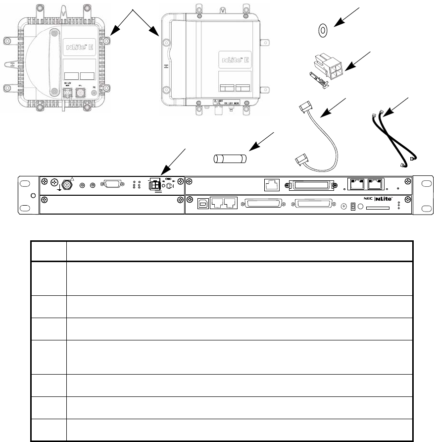
2.1 Packages
Each unpacked component of the [ ] GHz [ ] MB digital radio system
must be checked as shown below.
CONTENS LIST DRAWING NO.
MDP and TRP Fig. 2-2
Mounting Bracket Fig. 2-4
Installation Kit Fig. 2-5 and Fig. 2-7
ROI-S07045 INSTALLATION
2-3
Notes:*1 One more TRP and MODEM module are provided for HS/
Twinpath configuration.
*2 One spare fuse is provided in the MODEM module.
*3 TRP NHG Type: 6-38 GHz, TRP NHG2 Type: 6-8GHz/13-
38 HGz, TRP Mx Type: 52 GHz
Fig. 2-2 Contents of Basic Unit Package
3
1
2
4
5
67
(*1)
SELV
!
AUX/ALM
LCT NMS NE SC IN/OUT EOW
PROTECT
CALL MMC
MAINT
MEMORY
MDP
XIF IN XIF OUT
IF IN/OUT TX
RX
RESET
XPIC CTRL XPIC
PWR
TRP
MD/
CBL PWR
PULL
G
G
ALM
100M PORT 1 PORT 2 100M Ns
Ns DS1 IN/OUT
WS IN/OUT
N
(*1)
No. DESCRIPTION
1TRP-( )G-1B (NHG)/ TRP-( )G-5B (NHG2)/ TRP-6G-6AA (EHG)/
TRP-24G-2B*3
2 MDP-150MB-3AA (MDP)
3 O-Ring (Attached to the waveguide type TRP)
4Power Connector (Molex Housing M5557-4R (×1ea) and Socket Contact
(5556TL (× 4 each))
5 Cylindrical Fuse ((RKS-F91000-0107) (6.3A) (×1ea) *2)
6 XPIC CTRL Cable (×1) (apply for XPIC configuration only)
7 X-IF Coaxial Cable (×2) (apply for XPIC configuration only)
INSTALLATION ROI-S07045
2-4
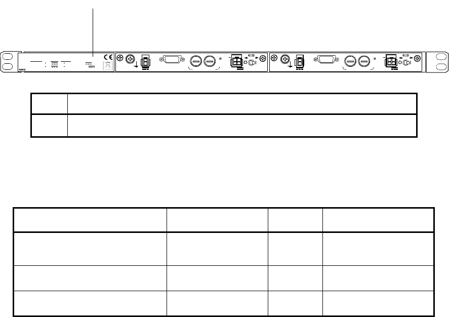
Fig. 2-3 Contents of Optional Unit Package
Νο
te:√: Usable
*1: TRP (NHP type) can not be used with DC-DC CONV.
*2: ALL INDOOR TRP can not be used with NWA-0011060-001 (24/
48V type).
SELV
PWR PULL
PWR
ALM FUSE (250V/8AH)
−
43V
G
OUT
STD
G
SELV
PWR PULL
PWR
ALM FUSE (250V/8AH)
−
43V
G
OUT
STD
G
NWA-011060-001 DC-DC CONV UNIT
SER No. DATE ,
WEIGHT 2.5kg
MADE IN JAPAN
NEC Corporat ion
TOKYO JAPAN
1+0 System STD Input : 20 60V 3.4A 1.0A
Output :
−
43V 1.3A
1+1 System STD Input : 20 60V 1.3A
×
2
3.4A 1.0A
×
2 Output :
−
43V
1
No. DESCRIPTION
1 NWA-011060-[ ] DC-DC CONV UNIT (see Fig. 2-7 for details)
DC-DC CONV UNIT NHG/NHG2/EHG NHP ALL INDOOR TRP
NWA-0011060-001
(24/48V type) √*1 *2
NWA-011060-002 (48V type) √*1 √
NWA-011060-003 (24V type) √*1 √
ROI-S07045 INSTALLATION
2-5
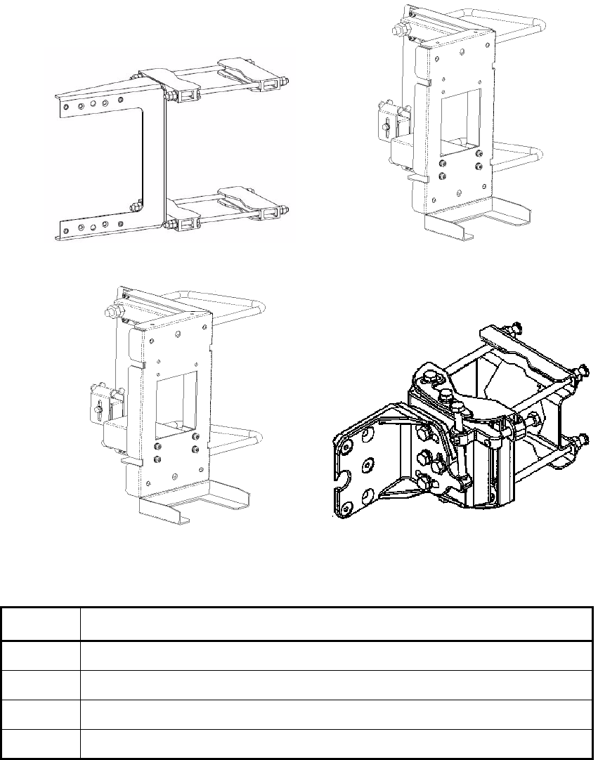
Fig. 2-4 Pole Mounting Bracket
(Supplied with Antenna)
3
21
4
No. DESCRIPTION
1 Pole Mounting Bracket for Coaxial Cable (6 GHz)/Waveguide Connection Type
2 Pole Mounting Bracket for Coaxial Cable Connection Type (6 GHz)
3 Pole Mounting Bracket for Wave Guide connection Type
4 Pole Mounting Bracket for Antenna direct Mounting Type
INSTALLATION ROI-S07045
2-6
SELV
!
AUX/ALM
LCT NMS NE SC IN/OUT EOW
PROTECT
CALL MMC
MAINT
MEMORY
MDP
XIF IN XIF OUT
IF IN/OUT TX
RX
RESET
XPIC CTRL XPIC
PWR
TRP
MD/
CBL PWR
PULL
G
G
Ns
N
100M PORT 3 PORT4 100M
ALM
DS1 IN/OUT
WS IN/OUT
Ns
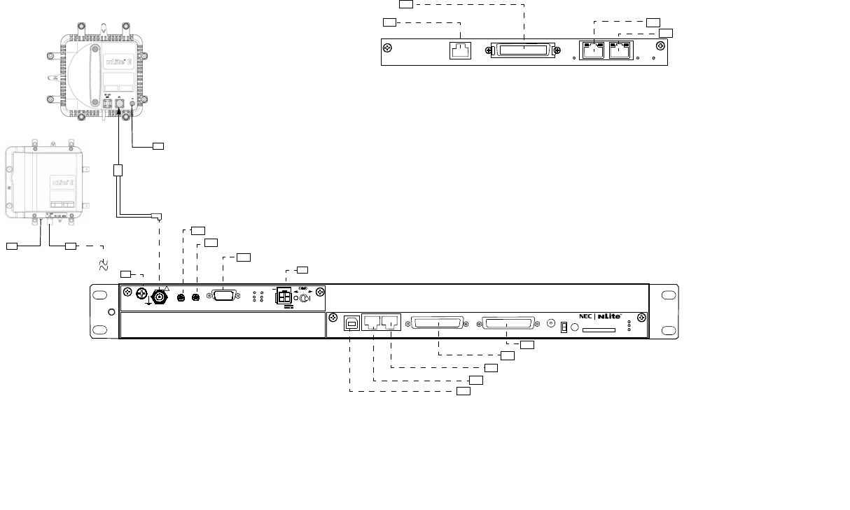
Fig. 2-5 Installation Kit Packing List of MDP and TRP for 1+0 System
MDP
No.1 TRP
MOLEX CONNECTOR/ (FEMALE)
LUG D-SUB Accessory cable/(MALE)
D-SUB CONNECTOR/(MALE)
D-SUB CONNECTOR/(MALE)
MODULAR CONNECTOR/(MALE)
MODULAR CONNECTOR/(MALE)
USB CONNECTOR/(MALE)
N-P CONNECTOR
(MALE)
TNC-P CONNECTOR (MALE)
LUG
Notes: 1. It is recommended that TNC (Male) L-angle connector for the 8D-FB IF cable is used to connect it to the MDP.
When the N (Male) straight connector is attached to the 5D-FB or 10D-FB IF cable, use of the TNC (Male) - N
(Female) (NJ-TNCP-LA) L-angle adapter is needed.
2P LAN INTFC
1053J8A (P) Accessory cable
1053J8A (P) Accessory cable
MDR CONNECTOR/(MALE)
MODULAR CONNECTOR/(MALE)
MODULAR CONNECTOR/(MALE)
MODULAR CONNECTOR/(MALE)
(NHG/NHP Type)
Note: Use the typical USB shielded cable. (Do not use the un-shielded cable.)
LUG
(NHG2 Type)
N-P CONNECTOR
(MALE)
ROI-S07045 INSTALLATION
2-7
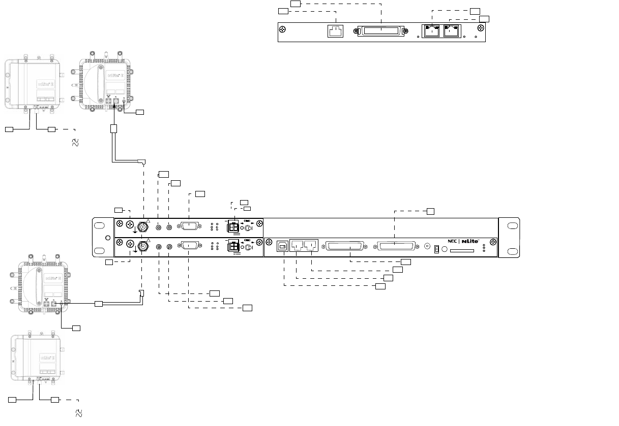
Fig. 2-6 Installation Kit Packing List of MDP and TRP for 1+1 System
N-P CONNECTOR (MALE)
LUG
LUG
TNCTNCTNC-P
CONNECTOR (MALE)
MDP
No.1 TRP
MOLEX CONNECTOR/ (FEMALE)
LUG MOLEX CONNECTOR/(FEMALE)
D-SUB Accessory cable/(MALE)
N-P CONNECTOR
(MALE)
TNC-P CONNECTOR (MALE)
LUG
2P LAN INTFC
1053J8A (P) Accessory cable
1053J8A (P) Accessory cable
MDR CONNECTOR/(MALE)
MODULAR CONNECTOR/(MALE)
MODULAR CONNECTOR/(MALE)
D-SUB Accessory cable/(MALE)
1053J8A (P) Accessory cable
1053J8A (P) Accessory cable
D-SUB CONNECTOR/(MALE)
D-SUB CONNECTOR/(MALE)
MODULAR CONNECTOR/(MALE)
MODULAR CONNECTOR/(MALE)
USB CONNECTOR/(MALE)
Notes: It is recommended that TNC (Male) L-angle connector for the 8D-FB IF cable is used to connect
it to the MDP. When the N (Male) straight connector is attached to the 5D-FB or 10D-FB IF
cable, use of the TNC (Male) - N (Female) (NJ-TNCP-LA) L-angle adapter is needed.
MODULAR CONNECTOR/(MALE)
(NHG/NHP Type)
(NHG/NHP Type)
No.2 TRP
Note: Use the typical USB shielded cable.
(Do not use the un-shielded cable.)
100M PORT 3 PORT4 100M
ALM
DS1 IN/OUT
WS IN/OUT
Ns
SELV
!
AUX/ALM
LCT NMS NE SC IN/OUT EOW
PROTECT
CALL MMC
MAINT
MEMORY
MDP
XIF IN XIF OUT
IF IN/OUT TX
RX
RESET
XPIC CTRL XPIC
PWR
TRP
MD/
CBL PWR
PULL
G
SELV
!
XIF IN XIF OUT
IF IN/OUT TX
RX
RESET
XPIC CTRL XPIC
PWR
TRP
MD/
CBL PWR
PULL
G
G
Ns
Ns
N
LUG
(NHG2 Type)
N-P CONNECTOR
(MALE)
LUG
(NHG2 Type)
N-P CONNECTOR
(MALE)
INSTALLATION ROI-S07045
2-8
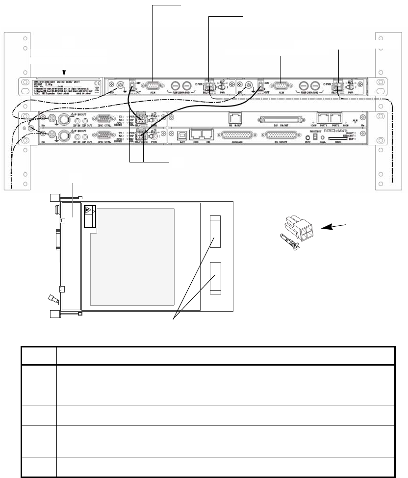
Notes:*1 One more TRP and MODEM module are provided for HS/
Twinpath configuration.
*2 Two spare fuses are provided in the DC-DC CONV module.
Fig. 2-7 Installation Kit Packing List of DC-DC CONV UNIT for 1+1 System
MOLEX CONNECTOR/(FEMALE)
MOLEX CONNECTOR/(FEMALE)
D-SUB CONNECTOR/(FEMALE)
D-SUB CONNECTOR/(FEMALE)
DC-DC CONV UNIT
(Optional)
4
5
1
3
RESERVE RESERVE
CAUTION
HOT SURFACE
Avoid contact.
!
2
No. DESCRIPTION
1 NWA-011060-[ ] DC-DC CONV UNIT
2 H3040[ ] DC-DC CONV
3 Power Cable (NWM-005773-001, attached to the DC-DC CONV)
4Power Connector (Molex Housing M5557-4R (×1ea) and Socket Contact
(5556TL (×4 each))
5 Cylindrical Fuse ((CBE-006255-001) (8A) (×2 ea) *2)
ROI-S07045 INSTALLATION
2-9
2.2 Unpacking of MDP and TRP
The unpacking procedures for the MDP and TRP are shown in following
chart.
•MDP: Chart 2-1
•TRP: Chart 2-2
Note: When conveying the MDP or TRP to another place, the original
packing should be used to avoid damage.
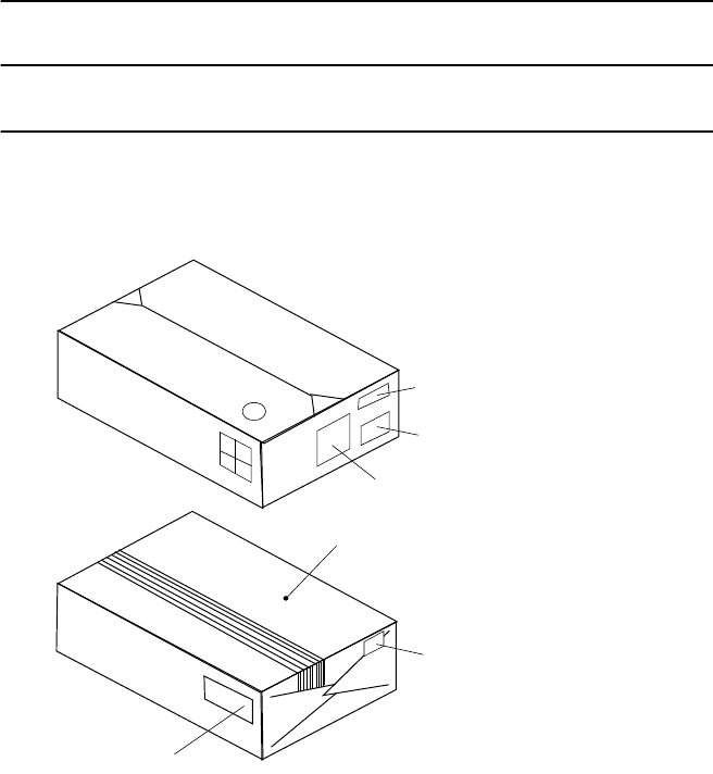
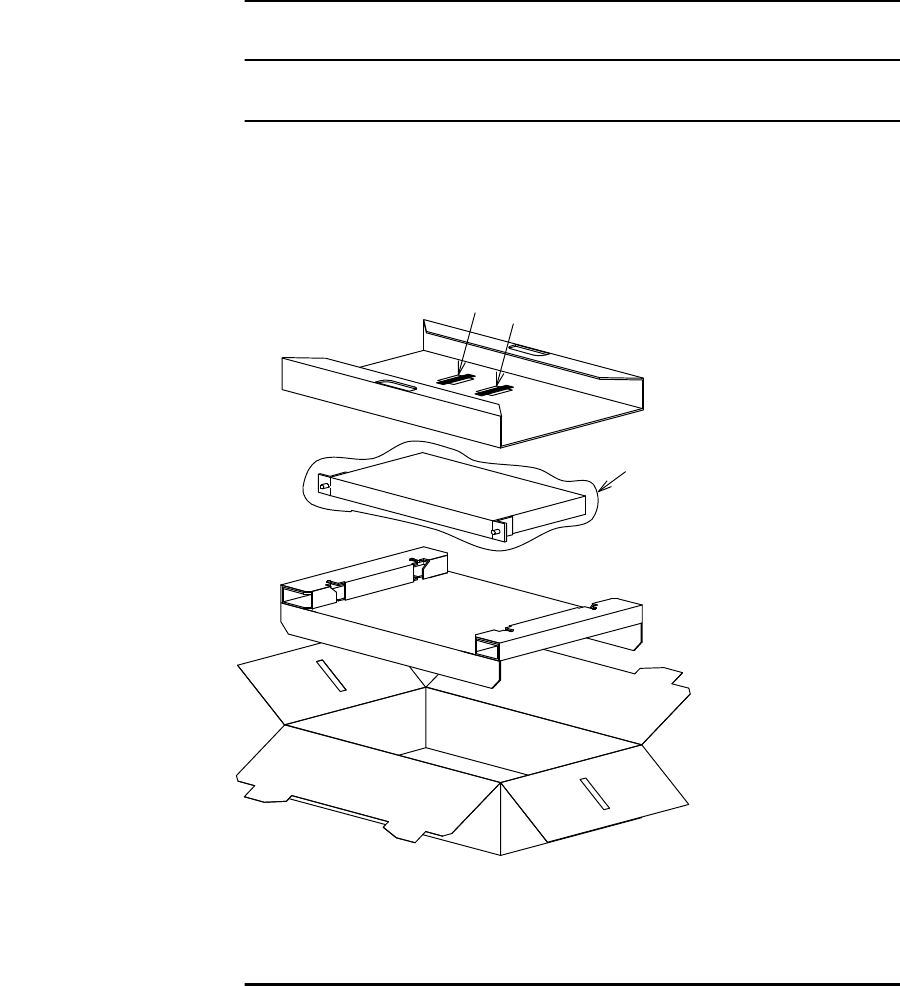
Chart 2-1 Unpacking Method for MDP
Step Procedure
1 Cut the p.p. tape at top of the carton. Then open the carton,
PACKAGE LABEL
INITIAL KEY INDICATION LABEL
PACKING LABEL
BARRIER MATERIAL
PACKAGE LABEL
CARE MARK LABEL
INSTALLATION ROI-S07045
2-10
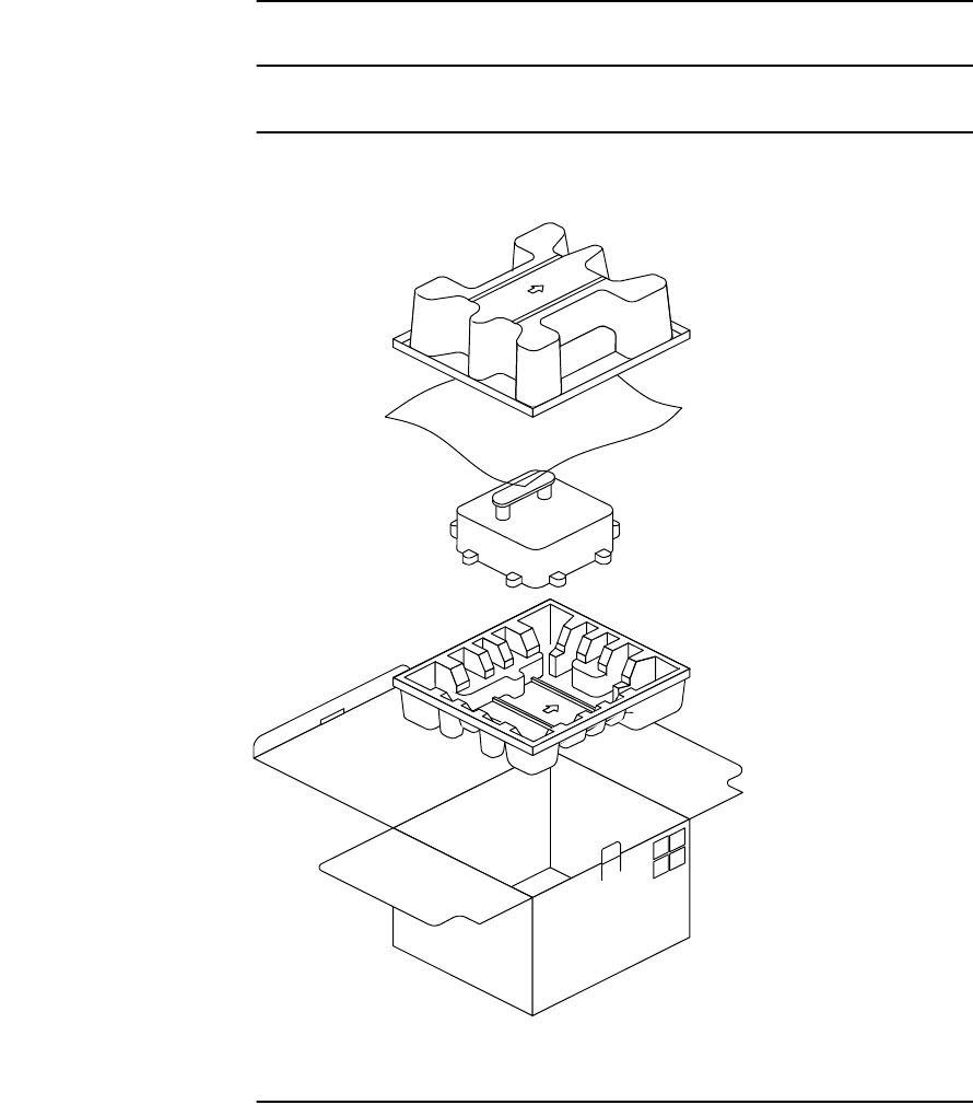
Chart 2-1 (Cont’d)
Step Procedure
2 Take out the accessories, MDP wrapped in the poly sheet and
cushioning materials (pads),
3 Take out the MDP from the poly sheet,
4 Inspect the MDP.
ATTACHMENT
DESICCANT
TOP PAD
POLY SHEET
BOTTOM PAD
INNER PACKING BOX
PRODUCT
ROI-S07045 INSTALLATION
2-11
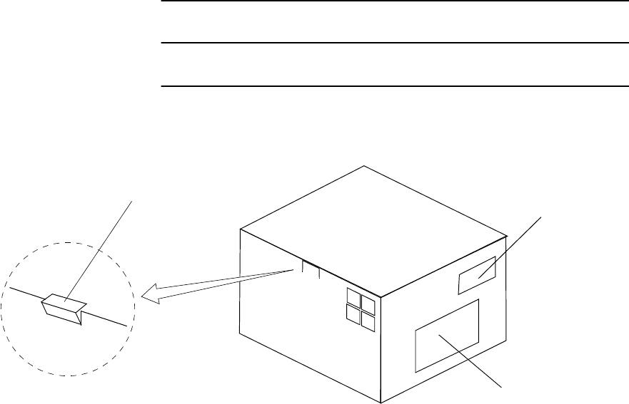
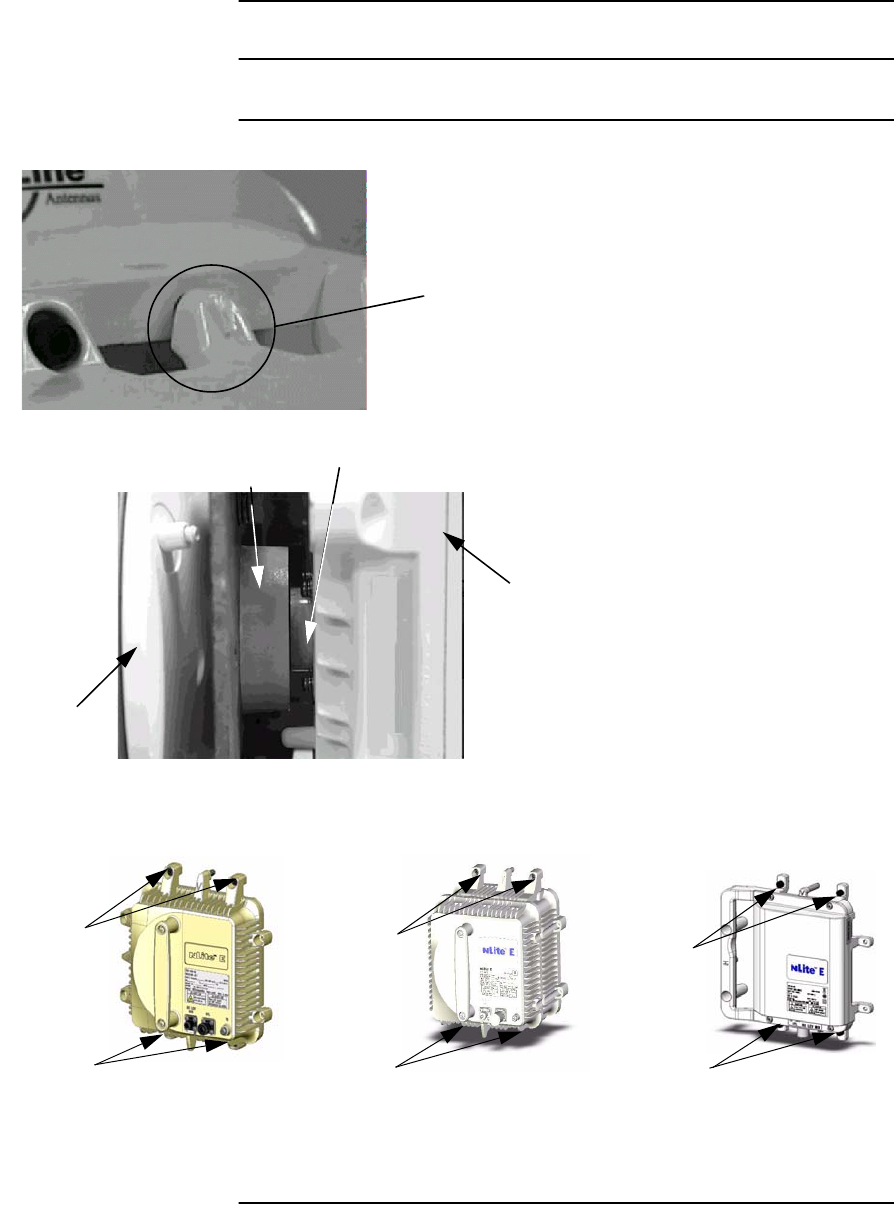
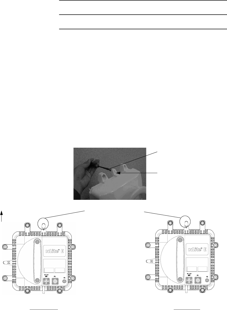
Chart 2-2 Unpacking Method for TRP
Step Procedure
1 Take off the hook of a cover as shown below. Then, open the top
cover,
HOOK
PACKAGE LABEL
PACKAGE LABEL
INSTALLATION ROI-S07045
2-12
Chart 2-2 (Cont’d)
Step Procedure
2 Take out the TRP, cushioning materials (pads) and poly sheet,
3 Inspect the TRP.
TOP PAD
POLY SHEET
ODU
BOTTOM PAD
INNER PACKING BOX
TOP PAD
POLY SHEET
TRP
BOTTOM PAD
INNER PACKING BOX
ROI-S07045 INSTALLATION
2-13
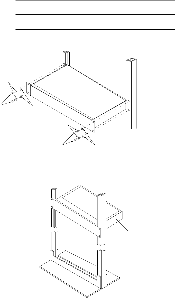
2.3 MDP Mounting
The installation procedure for the MDP explains in Chart 2-3. The MDP
should be installed in the radio station.
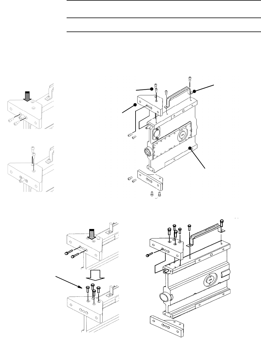
Chart 2-3 Mounting Methods of the MDP
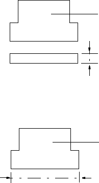
Step Procedure
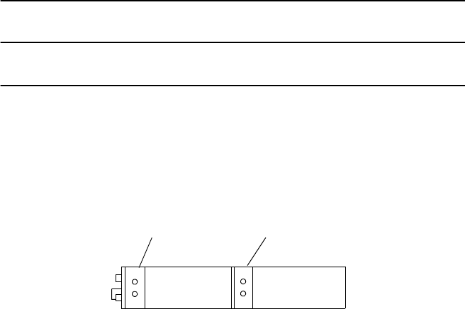
1 Change the two brackets to desired position on the MDP, if
necessary,
FRONT
POSITION CENTER
POSITION
SIDE VIEW
1+0/1+1 SYSTEM
INSTALLATION ROI-S07045
2-14
Chart 2-3 (Cont’d)
Step Procedure
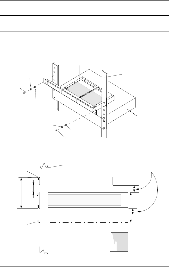
2 Align the MDP to the mounting position on the 19-inch rack,
3 Fix each side of the MDP to the 19-inch rack with the two
screws,
SCREW FLAT WASHER
SCREW FLAT WASHER
SPRING WASHER
SPRING WASHER
MDP
ROI-S07045 INSTALLATION
2-15
Chart 2-3 (Cont’d)
Step Procedure
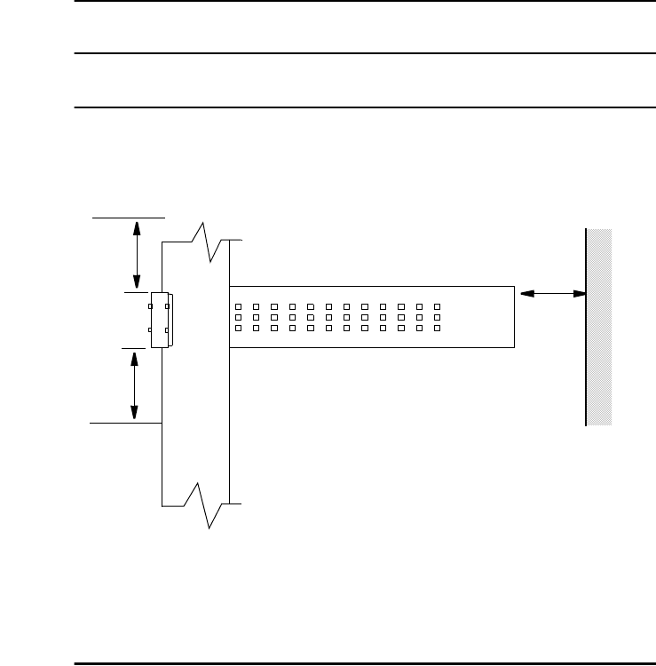
4 To mount the MDP in a 19-inch rack, take a space more than
200 mm to the rear section and space for one unit to the top and
bottom.
At least
one rack unit *
At least
one rack unit *
More than
200 mm *
Note: * Normal setting for free space. When free space is closed within
one rack unit, keep the environment temperature is lower than
+40
°
C.
WALL
INSTALLATION ROI-S07045
2-16
2.4 DC-DC CONV UNIT Mounting (Optional)
The installation procedure for the DC-DC CONV UNIT (optional)
explains in Chart 2-4. The DC-DC CONV UNIT (optional) should be
installed in the radio station.
Chart 2-4 Mounting Methods of the DC-DC CONV UNIT
Step Procedure
1 Fix the DC-DC CONV UNIT to the 19-inch rack using the two
screws.
At least
0.5 rack unit *
MDP
DC-DC CONV UNIT
SCREW
SPRING
WASHER
SCREW
FLAT
SPRING
WASHER
WASHER
2U 0.5U
MDP
DC-DC CONV UNIT
DC-DC CONV UNIT
RACK
UPPER
SCREW HOLE
LOWER
SCREW HOLE
Note: * Space 0.5 rack unit in the upper or lower DC-DC CONV
UNIT.
2U
FLAT
WASHER
DC-DC CONV UNIT
RACK

ROI-S07045 INSTALLATION
2-17
2.5 TRP Mounting
The procedures for mounting and demounting the TRP are described here.
There are two types of mounting for the antenna direct mounting type and
waveguide connecting type. The TRP should be installed in the radio
station. The tools for installation are listed in Table 2-1.
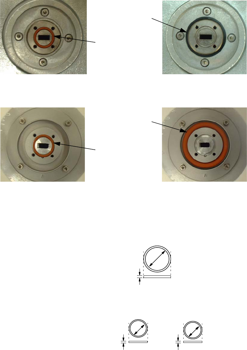
Cautions: 1. How to use small and large O-rings are shown in
following table. Two (small and large) O-rings are
attached in 18 to 38 GHz band Andrew/RFS direct
mount antenna. 11 GHz band antenna does not have
small O-ring (Small O-ring is not used for Andrew/RFS
direct mount antenna). If the small O-ring is used for
TRP direct mount installation, a gap may occur between
TRP and antenna for RF interface. Therefore it may
happen transmit or receive level down.
2. Do not apply silicon grease at O-ring.
Note: 11 GHz antenna for direct mount is not possible to connect the
ordinary waveguide flanges.
Table 2-1 Tools
TOOLS
Wrench or Monkey wrench
Screwdriver
Torque Wrench
SYSTEM ATTACHENENT
POSITION OF
O-RING (BETWEEN:)
O-RING REMARKS
SMALL SIZE LARGE SIZE
1+0
ANT ⎯ TRP Not used Used Antenna direct mounting
ANT ⎯ WG/TRP
(18-38 GHz BAND) Used Not used Waveguide connection
1+1
ANT ⎯ HYB/
COUPLER Not used Used Antenna direct mounting
ANT ⎯ WG/HYB/
COUPLER
(18-38 GHz BAND)
Used Not used Waveguide connection
INSTALLATION ROI-S07045
2-18
Notes: 1. Do not use both small O-ring and large O-ring
simultaneously.
2. O-ring size is different with frequency band as follows:
POSITION
OF LARGE
SIZE O-RING
POSITION
OF SMALL
SIZE O-RING
FOR WAVEGUIDE CONNECTION FOR ANTENNA DIRECT MOUNTING
ANDREW ANTENNA
POSITION
OF LARGE
SIZE O-RING
POSITION
OF SMALL
SIZE O-RING
FOR WAVEGUIDE CONNECTION FOR ANTENNA DIRECT MOUNTING
RFS ANTENNA
LARGE SIZE O-RING FOR ANTENNA DIRECT MOUNTING
40mm
11 GHz BAND
4 mm
18/23 GHz BAND 38 GHz BAND
15.6mm
SMALL SIZE O-RING FOR WAVEGUIDE CONNECTION
10.8mm
1.8 mm
1.8 mm

ROI-S07045 INSTALLATION
2-19
2.5.1 Mounting
The method of mounting is listed in Table 2-2 to Table 2-4.
Installation manuals of NEC Pasolink Antenna are attached at Appendix
NEC PASOLINK ANTENNA.
Table 2-2 Antenna Direct Mounting
Change of Polarization TRP/
Bracket HYB/
COUPLER TX SPAN
ATT OMT
Chart 2-5
ANT/TRP/HYB/COUPLER/TX
SPAN ATT Chart 2-6 Chart 2-7 Chart 2-8 Chart 2-11
Table 2-3 Waveguide Connection
Using 1+1 HYB 1+0 or Connecting Two Antennas
Chart 2-10 Chart 2-12
Table 2-4 Coaxial Cable Connection
With/Without HYB/COUPLER
Chart 2-15
INSTALLATION ROI-S07045
2-20
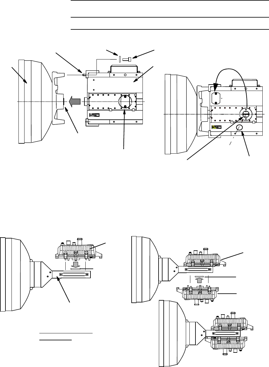
Chart 2-5 Change of Polarization (Antenna Direct
Mounting)
Step Procedure
CHANGE OF POLARIZATION
TRP DIRECT MOUNTING TYPE ANTENNA
(Example (ANDREW) 1/2)
Notes: 1. The details are referred to the installation manual which
is attached to the antenna. The installation or removal of
the antenna requires qualified experienced personnel.
2. The antenna is set to V-polarization when shipped from
the factory.
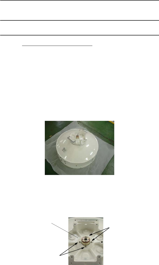
1 Keep the antenna stand horizontally.
2 If you change to H polarization, loosen the four screws with the
Allen key wrench and then rotate the Transition hub of feed,
keeping the antenna stand horizontal.
TRANSITION HUB
2 SCREWS
2 SCREWS
ROI-S07045 INSTALLATION
2-21
Chart 2-5 (Cont’d)
Step Procedure
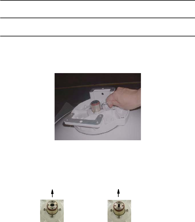
Note: Do not remove the screw complete from the screw hole.
Hold the feed horn with hand.
3 Holding the feed with hand, rotate the feed 90 degrees.
Check that the aperture part of the Transition hub is rotated 90
degrees, then fix it with the screws that were loosened in step 2.
4 Check that the aperture part of the Transition hub is rotated 90
degrees, then fix it with the screws that were loosened in step 2
Note: When a large and a small gasket are included in the
antenna package. Please use the large one (The small
gasket is not used in antenna mount).
POLARIZATION
V
POLARIZATION
H
TOP TOP
INSTALLATION ROI-S07045
2-22
Chart 2-5 (Cont’d)
Step Procedure
CHANGE OF POLARIZATION
TRP DIRECT MOUNTING TYPE ANTENNA
(Example (ANDREW) 2/2)
Notes: 1. The details are referred to the installation manual which is
attached to the antenna. The installation or removal of the
antenna requires qualified experienced personnel.
2. The antenna is set to V-polarization when shipped from the
factory.
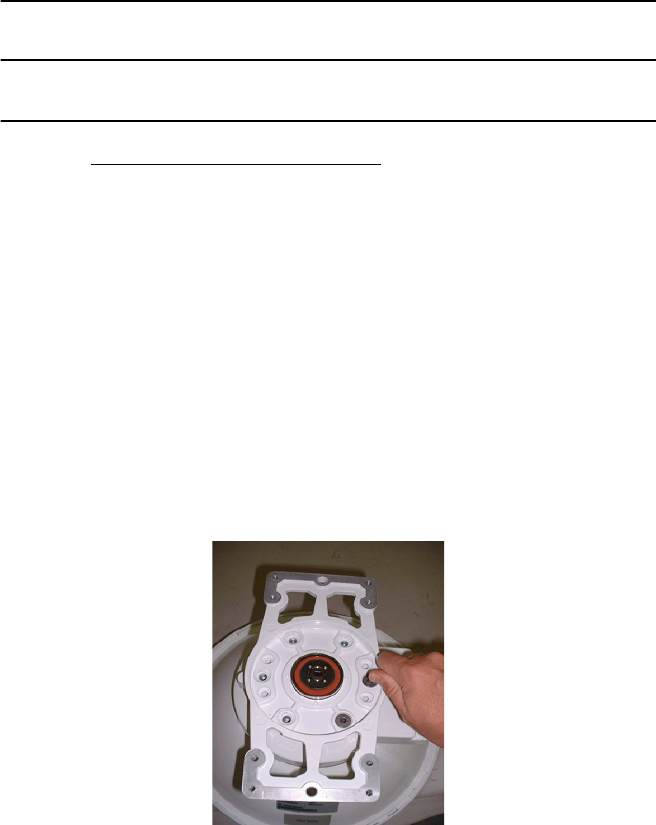
1. Keep the antenna stand horizontally.
2. Loosen six screws with Allen wrench until transition can rotate
freely.
Notes:1. Do not remove the screw complete from the screw hole.
2. Because of the screwtight is applied, the strength to
loosen screw is necessary.
3 Rotate the transition hub 90 degrees until timing pin locates in
timing concavity.
ROI-S07045 INSTALLATION
2-23
Chart 2-5 (Cont’d)
Step Procedure
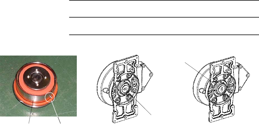
Tighten six screws when transition hub is located. (Tightening
torque is 5.0 N·m ± 10%.)
VERTICAL POLARIZED APPLICATION HORIZONTALLY POLARIZED APPLICATION
TRANSITION HUB
TRANSITION HUB
TIMING PIN
TRANSITION HUB
INSTALLATION ROI-S07045
2-24
Chart 2-5 (Cont’d)
Step Procedure
CHANGE OF POLARIZATION
TRP DIRECT MOUNTING TYPE ANTENNA
(Example (RFS))
Notes: 1. The details are referred to the installation manual which is
attached to the antenna. The installation or removal of the
antenna requires qualified experienced personnel.
2. The antenna is set to V-polarization when shipped from the
factory.
4 SCREWS (M3)
RFS SB1
1. Unscrew the 4 screws M3 at the refined
steel ring.
2. Hold the feed tightly at the waveguide.
3. Rotate carefully the feed 90 degrees.
4. Mount the feed to the refined steel ring
and lock the 4 screws M3.
RFS C-MOUNT
DRAIN PLUG
DRAIN PLUG
POLARIZATION V POLARIZATION H
1. Loosen the 4 screws M3.
2. Hold the feed tightly at the waveguide.
3. Rotate the casting plate carefully the
feed 90 degrees.
4. Lock the 4 screws M3.
ROI-S07045 INSTALLATION
2-25
Chart 2-5 (Cont’d)
Step Procedure
CHANGE OF POLARIZATION OF THE HYB/COUPLER
NEC HYBRID/COUPLER
Note:The hybrid/coupler is set to V-polarization when shipped from the
factory.
1 If you change the polarization from V to H, loosen two screws,
rotate the transition hub and put it to the HYB/COUPLER.
Note: There are two types NEC HYBRID/COUPLER. One uses two
pieces transition hubs and another uses one piece.
2 Then fix it with the two screws that were loosened in step 1.
TRANSITION
HUB
V POLARIZATION
GUIDE PIN
HYB/COUPLER
V POLARIZATION H POLARIZATION
Two Pieces Transition Hub Type
H POLARIZATIONV POLARIZATION
One Piece Transition Hub Type
(Only for 11/18/23/24(26)/38 GHz HYBRID/COUPLER)
M2.6(2ea)
Cross-Recessed
Head Machine Screw
Cross-Recessed
Head Machine Screw
M2.6 (2ea)
Cross-Recessed
Head Machine Screw
M2.6 (2ea)
INSTALLATION ROI-S07045
2-26
Chart 2-5 (Cont’d)
Step Procedure
Quasar HYBRID
Note: The hybrid is set to V-polarization when shipped from the factory.
1 If you change to H polarization, loosen two screws, rotate the
antenna connection unit and put the HYB horizontally.
2 Check that the aperture of the connection unit is rotated as
shown below, then fix it with the two screws that were loosened
in step 1.
HYB
ANTENNA
CONNECTION UNIT
V POLARIZAION
GUIDE PIN
SCREW
Quasar HYB
V POLARIZATION
H POLARIZATION
ROI-S07045 INSTALLATION
2-27
Chart 2-5 (Cont’d)
Step Procedure
CHANGE OF POLARIZATION OF THE TX SPAN ATT
TX SPAN ATT
Note: The TX ATT is set to V-polarization when shipped from the
factory.
1 If you change to H polarization, loosen two screws, rotate the
antenna connection unit and put the TX ATT horizontally.
2 Check that aperture of the connection unit is rotated as shown
below, then fix it with the two screws that were loosened in
step 1.
TX ATT
ANTENNA
CONNECTION UNIT
V POLARIZATION
GUIDE PIN
CROSS-RECESSED
HEAD MACHINE SCREW
M2.6(2ea)
PLATE-2
PLATE-1
H POLARIZATION
V POLARIZATION
38 GHz Band TX SPAN ATT Polarization Change
INSTALLATION ROI-S07045
2-28
Chart 2-5 (Cont’d)
Step Procedure
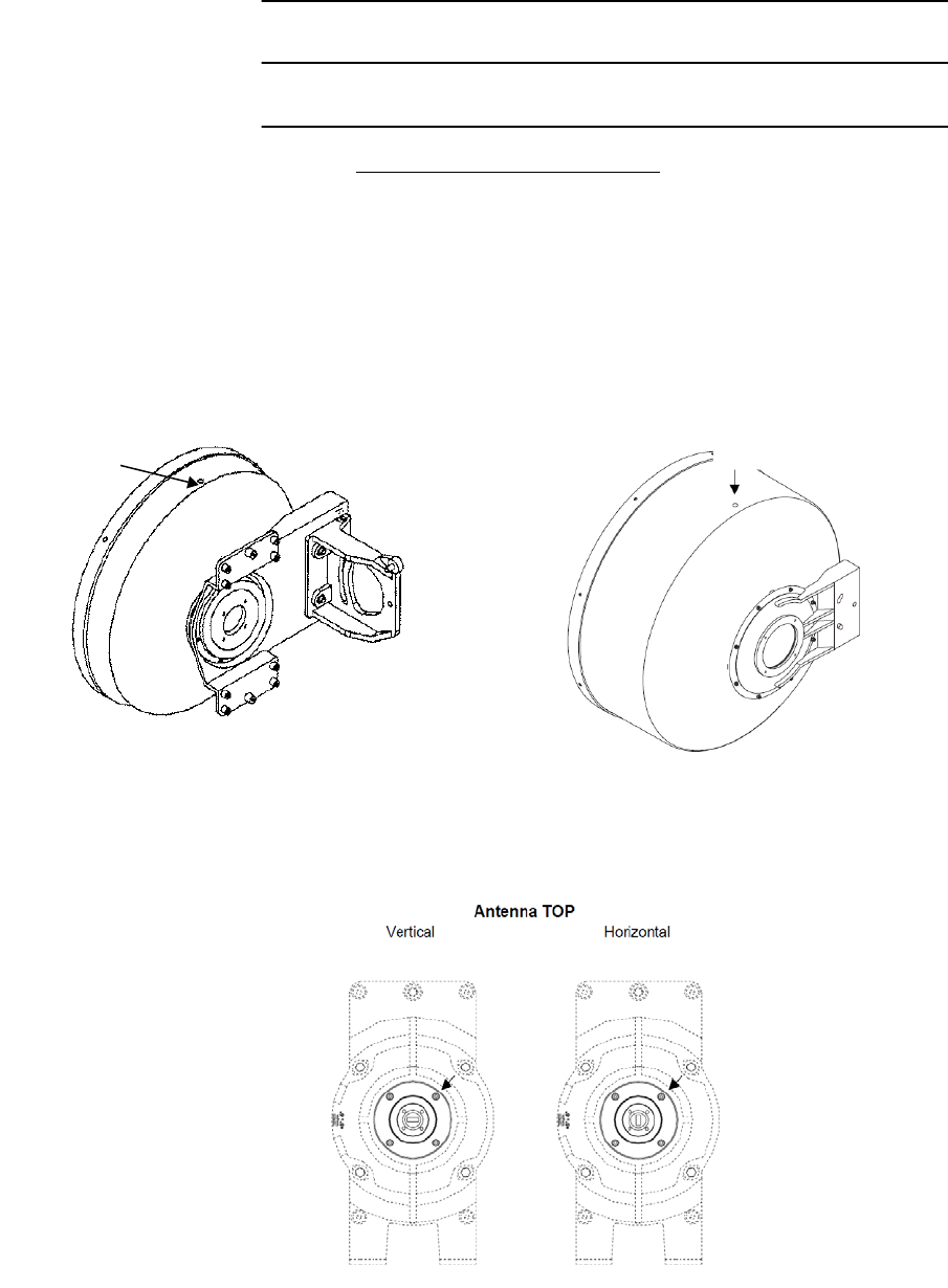
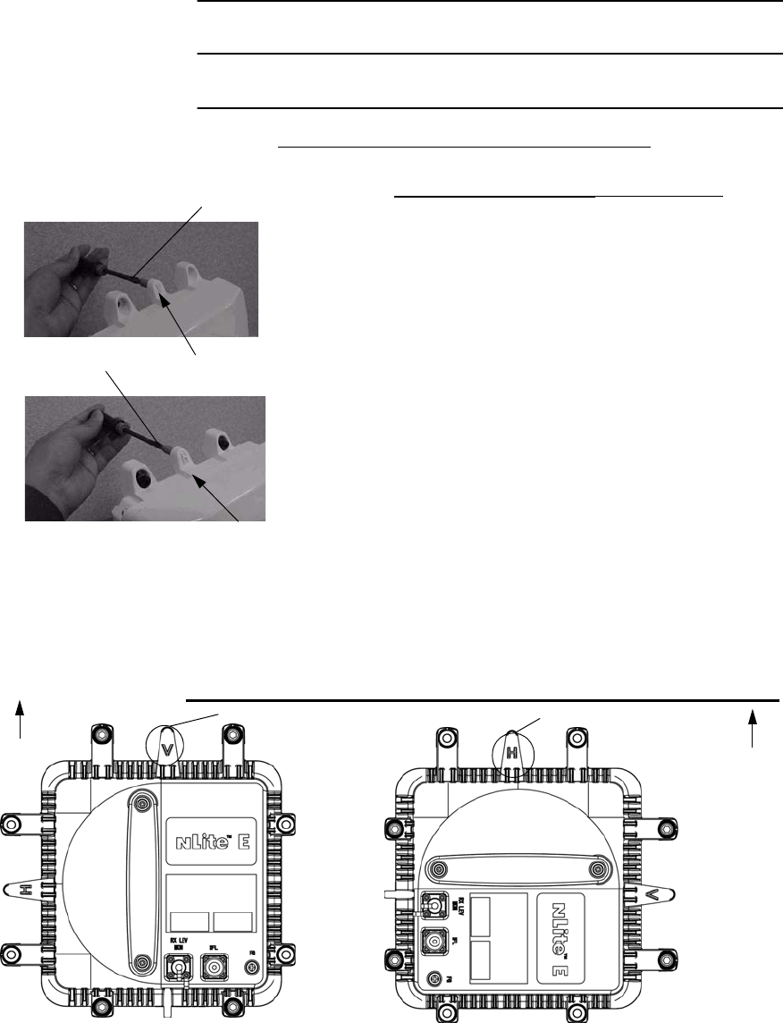
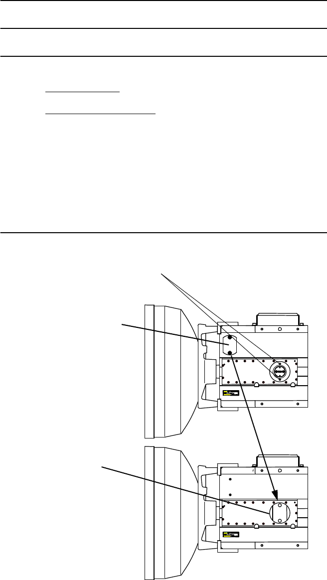
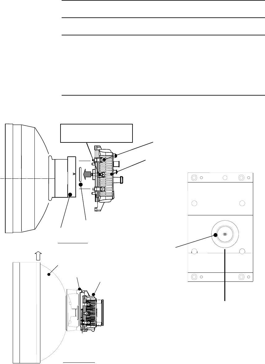
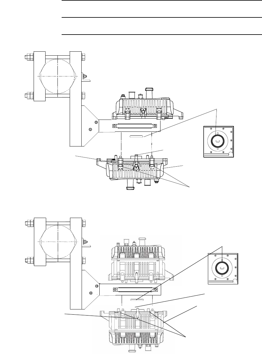
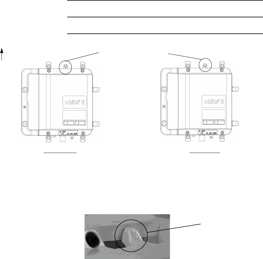
CHANGE OF POLARIZATION OF THE TRP
1. When vertical polarization is required, rotate
the TRP so as to go up the plate marked V.
2. When horizontal polarization is required,
remove the guide pin fixed on the plate
marked with V.
3. Screw in the guide pin removed in step 2 to
the screw hole of the plate marked H.
4. Rotate the TRP so as to go up the plate
marked H.
PLATE MARKED WITH V
UP
V POLARIZATION
PLATE MARKED WITH H
UP
H POLARIZATION
GUIDE PIN
PLATE MARKED WITH V
GUIDE PIN
PLATE MARKED WITH H
Antenna Mounting TRP (11-38 GHz Band)
Notes: 1. When the TRP is mounted on to the NEC HYB/
COUPLER, only V polarization is applied.
2. When the Waveguide or coaxial cable is connected
between the TRP and antenna, the TRP in V
polarization for up position is recommended for
installation.
V/H Polarization Conversion
11-38 GHz TRP (NHG Type)
ROI-S07045 INSTALLATION
2-29
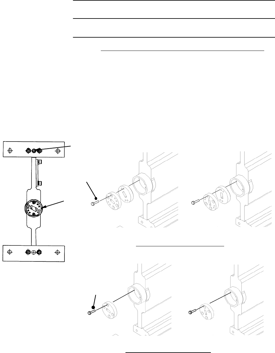
Chart 2-5 (Cont’d)
Step Procedure
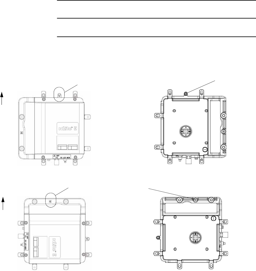
V POLARIZATION
PLATE MARKED V Guide Pin
UP
V/H Polarization Conversion
13-38 GHz TRP (NHG2 Type)
PLATE MARKED H Guide Pin
UP
H POLARIZATION
INSTALLATION ROI-S07045
2-30
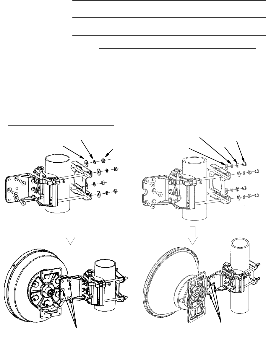
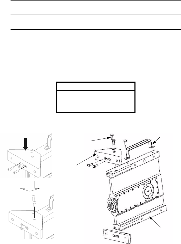
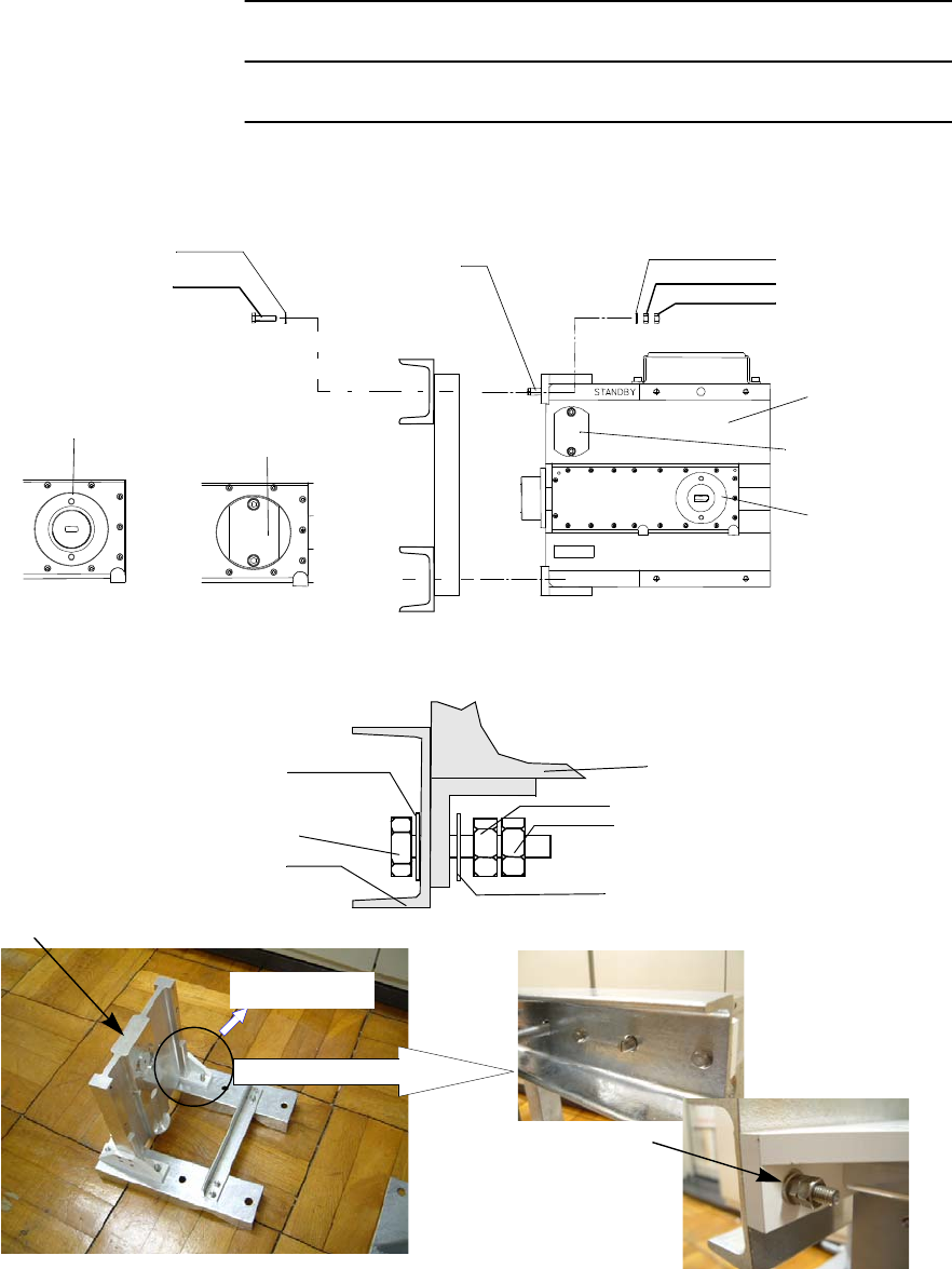
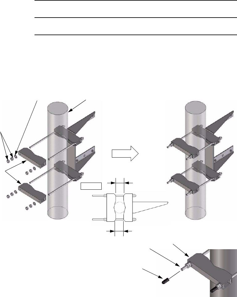
Chart 2-6 TRP Antenna Direct Mounting (11 - 38 GHz)
Step Procedure
ANTENNA DIRECT MOUNTING (11-38 GHz Band TRP)
Note: The details are referred to the installation manual which
is attached to the antenna.
INSTALLATION OF BRACKET
1 Install the bracket to the antenna pole.
2 Mount antenna to the bracket.
ANDREW POLE MOUNT BRACKET
WASHER
LOCK WASHER
NUT*
WASHER
Note: *: Tightening torque of 22 N·m for M10.
Three(3) screws*
(Apply screwtight to threads
before fitting to antenna)
NUT*
PROTECTIVE
CAP
LOCK WASHER
Three(3) screws*
(Apply screwtight to threads
before fitting to antenna)
ROI-S07045 INSTALLATION
2-31
Chart 2-6 (Cont’d)
Step Procedure
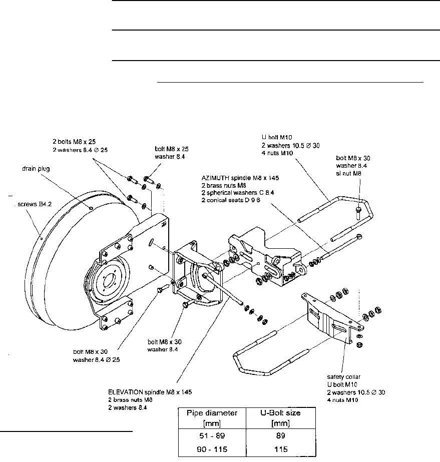
ANTENNA DIRECT MOUNTING (11-38 GHz Band TRP)
RFS SB1 TYPE BRACKET

INSTALLATION ROI-S07045
2-32
Chart 2-6 (Cont’d)
Step Procedure
Note: The values in the following table are valid for screws and bolts
which have been greased according to the installation
instructions.
Torques for RFS
Bolt M5 5 Nm
M6 8 Nm
M8 17 Nm
M10 35 Nm
M12 50 Nm
U-Bolt, V-Bolt (Pipe mount & safety collar) M10 20 Nm
Hexagonal brass nut of fine adjustment (Azimuth, Elevation) M8 5 Nm
M10 10 Nm
M12 17 Nm
Hexagonal socket stainless steel screws (Feed systems install on aluminium mounting plate) M3 0.2 Nm
M4 0.4 Nm
Exceptions
Fixing screw of the azimuth fine adjustment spindle M8 x 30 8 Nm
M12 x 55 17 Nm
Special application: NOT greased
Fixing screw of the plastic radome B4.2 3 Nm
ROI-S07045 INSTALLATION
2-33
Chart 2-6 (Cont’d)
Step Procedure
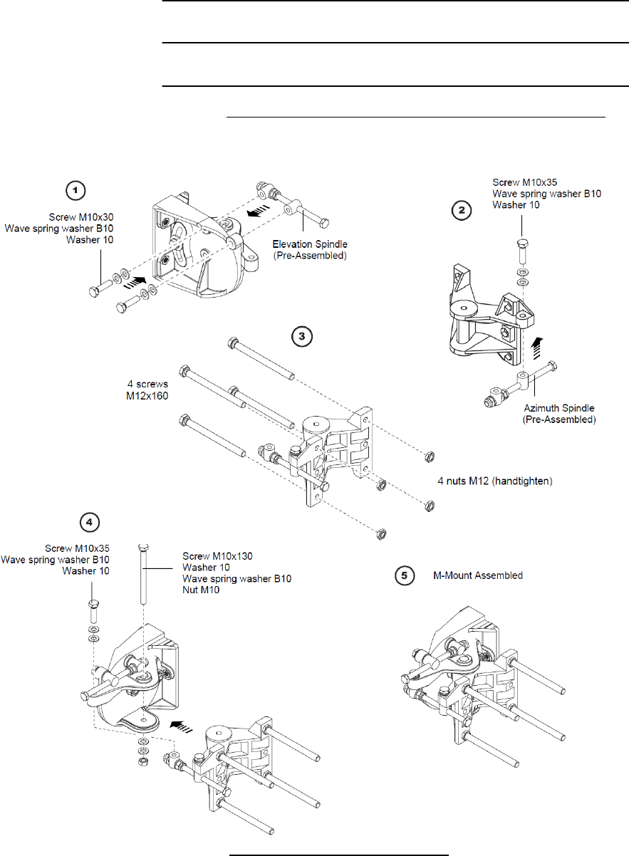
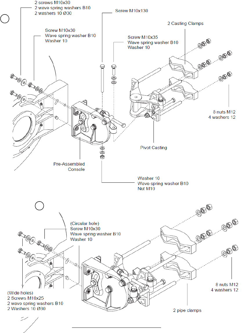
ANTENNA DIRECT MOUNTING (11-38 GHz Band TRP)
Pipe diameter: 48-114mm
RFS C-Mount TYPE BRACKET
MOUNT ASSEMBLY (RFS C-Mount Type)
INSTALLATION ROI-S07045
2-34
RFS C-Mount TYPE BRACKET
6
7
ROI-S07045 INSTALLATION
2-35
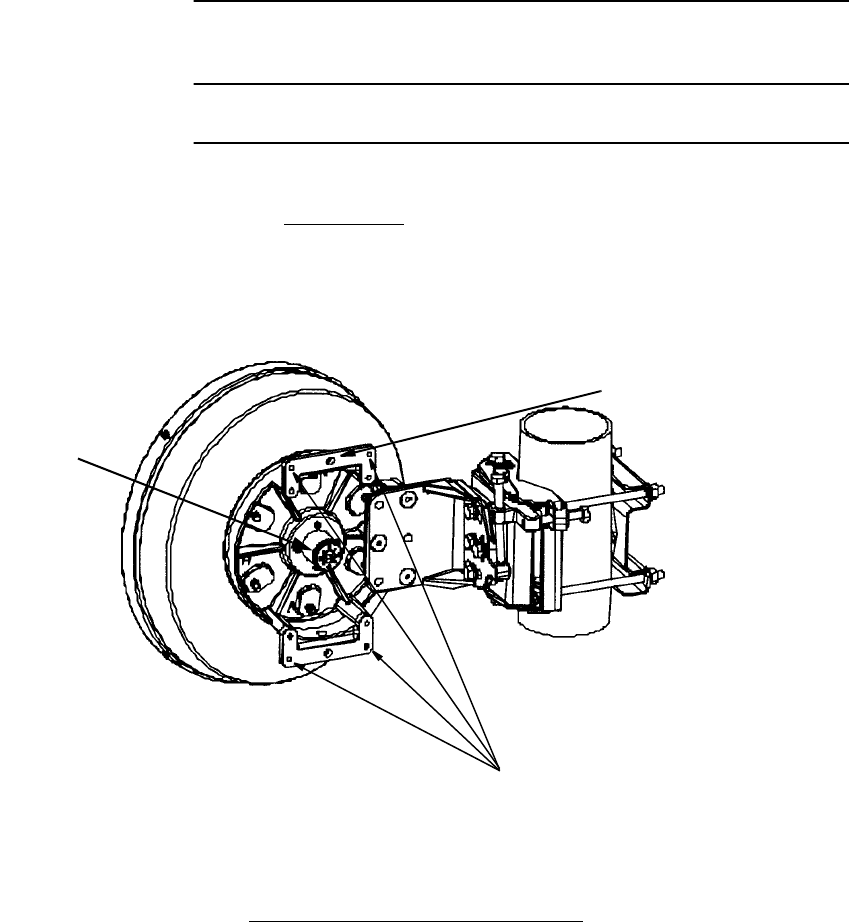
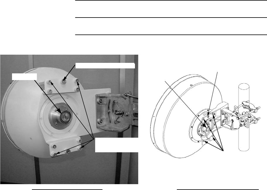
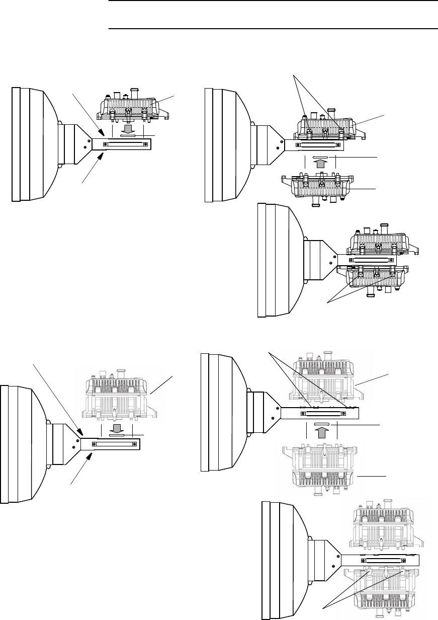
Chart 2-6 (Cont’d)
Step Procedure
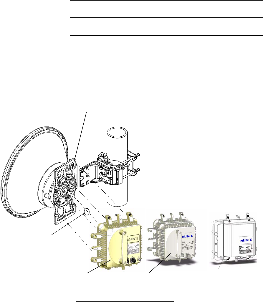
3 Fix the TRP to the bracket by tightening the M6 screws (four
locations).
Note: Being careful, tighten alternately and gradually four screws.
Notes: 1. Figure shows V polarization.
2. Be careful not to damage the O-ring (Antenna).
3. The tightening torque is 4.0 N·m ± 10%.
O-RING
HOLE FOR GUIDE PIN
TRP
ANDREW VHLP TYPE BRACKET
(NHG Type)
TRP
(NHP Type)
TRP
(NHG2 Type)
INSTALLATION ROI-S07045
2-36
Notes: 1. Figure shows V polarization.
2. Be careful not to damage the O-ring (Antenna).
3. The tightening torque is 4.0 N·m ± 10%.
Notes: 1. Figure shows V polarization.
2. Be careful not to damage the O-ring (Antenna).
3. The tightening torque is 4.0 N·m ± 10%.
RFS SB1 TYPE BRACKET
O-RING
HOLE FOR GUIDE PIN
TRP NHG Type TRP NHP Type TRP NHG2 Type
Note: Set the TRP to the bracket after
polarization of the TRP is
confirmed.
O RING
RFS C-Mount TYPE BRACKET
HOLE FOR GUIDE PIN
TRP NHG Type TRP NHP Type TRP NHG2 Type
ROI-S07045 INSTALLATION
2-37
Chart 2-6 (Cont’d)
Step Procedure
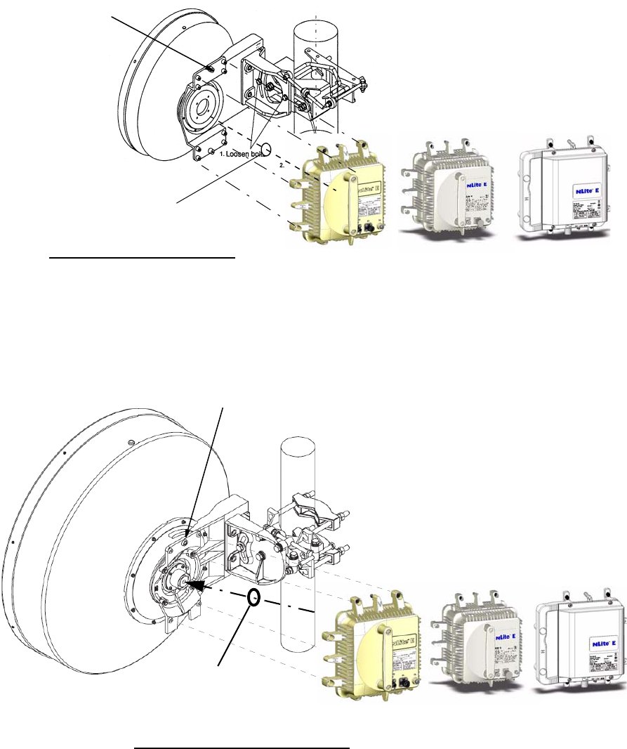
4. Insert guide pin on the hole of
bracket to set the position of screws.
GUIDE PIN
Caution: Align flanges on antenna
and TRP correctly, and fix
the TRP with four screws.
TRP
TRP FLANGE
ANTENNA FLANGE
ANTENNA
5. Fix the TRP to the bracket with four screws.
SCREWS
SCREWS
TRP NHG Type TRP NHP Type
SCREWS
SCREWS
SCREWS
SCREWS
TRP NHG2 Type
INSTALLATION ROI-S07045
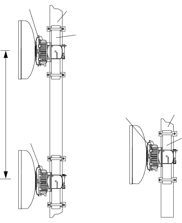
2-38
Note: Antenna separation (S) is given by path calculation depending on
the system parameter.
1+1 SD System
POLE
(S)
MEMBER OF TOWER
1+0 System
MEMBER OF TOWER
POLE
No.1 TRP
No.2 TRP
TRP
TRP NHG Type
TRP NHG Type
ROI-S07045 INSTALLATION
2-39
Chart 2-7 Antenna Direct Mounting Using HYB/
COUPLER
Step Procedure
MOUNTING
Note: The details are referred to the installation manual which is
attached to the antenna.
ANDREW VHLP TYPE BRACKET
MOUNTING HOLE FOR
HYB/COUPLER
HOLE FOR GUIDE PIN
Note: The tightening torque is 4.0 N·m ± 10%.
Be careful not to damage the O-ring (Antenna).
O-RING
INSTALLATION ROI-S07045
2-40
Chart 2-7 (Cont’d)
Step Procedure
Note: The tightening torque is 4.0 N·m ± 10%.
Be careful not to damage the O-ring (Antenna).
HOLE FOR GUIDE PIN
O-RING
RFS SB1 TYPE BRACKET RFS C-Mount TYPE BRACKET
MOUNTING HOLE
FOR HYB/COUPLER
O-RING
HOLE FOR GUIDE PIN
MOUNTING HOLE
FOR HYB/COUPLER
ROI-S07045 INSTALLATION
2-41
Chart 2-7 (Cont’d)
Step Procedure
1 Fix the bracket and handle to the HYB/COUPLER used for 11-
38 GHz TRP.
2 Check the polarization and install the HYB/COUPLER to the
antenna by tightening the M6 screws (four locations).
M5 HEAD CAP SCREW
Note: Tightening torque is
3.0 N·m ± 10%.
PUSH
Note: Tightening torque is 3.0 N·m ± 10%.
M5X12(10ea)
Bracket
Hybrid
Handle
M5 HEAD CAP SCREW
For 2 screws Type Bracket
For 4 screws Type Bracket
/Coupler
INSTALLATION ROI-S07045
2-42
Chart 2-7 (Cont’d)
Step Procedure
3 Insert the O-rings to the two TRP ports of the HYB/COUPLER.
4 Install the two TRPs with hex screws (four locations) using the
Allen key wrench.
Note: Be careful not to damage the O-rings (Hybrid/Coupler).
ANT
FLAT WASHER M6 SCREWGUIDE PIN
O-RING
SHORT PLATE
MOVE THE
SHORT PLATE
HYB/COUPLER
TRP PORT O-RING
Note: Tightening torque is
4.0 N·m ± 10%.
Note: Be careful not to damage the O-ring.
O-RING
TRP
O-RING
TRP
TRP
For 11-38 GHz TRP
Note: Tightening torque is 4.0 N·m ± 10%.
(NHG Type)
HYB/COUPLER
ROI-S07045 INSTALLATION
2-43
Chart 2-7 (Cont’d)
Step Procedure
DEMOUNTING
FROM HYB/COUPLER
1 Remove the four (or six) fixed bolts from the TRP.
2 Then demount the TRP.
Note: When demounting the TRP from HYB/COUPLER, mount the
attached SHORT PLATE to the demounted port of the HYB/
COUPLER to avoid RF power leaking from the hybrid/Coupler
and for waterproofing.
MOUNTING SHORT
PLATE TO THE TRP
PORT
MOUNTING HOLE
FOR SHORT
PLATE
SHORT
PLATE
Note: Tightening torque is 3.0 N·m ± 10%.
INSTALLATION ROI-S07045
2-44
Chart 2-8 Antenna Direct Mounting Using
TX SPAN ATT
Step Procedure
MOUNTING
TX SPAN ATT
1 Check the polarization of the antenna connection unit of the TX
ATT (Refer to CHANGING POLARIZATION description for
the TX ATT.)
2 Fix the TX ATT to the antenna by tightening the M6 screws
(four locations).
ANTENNA CONNECTION UNIT
TX ATT
ANTENNA
GUIDE PIN
TX ATT
FLAT WASHER M6 (4ea)
PACKING (SUPPLIED BY ANTENNA)
Installation to antenna
12
34
Note; Tightening torque (M6) is 4.0 N·m ± 10%.
Hexagon Socket Head
Cap Screw
M6 x 30 (4ea)
38 GHz Band TRP Mounting Using NEC TX SPAN ATT (1/2)
Tighten the each
screw equally and
carefully by wrench
at diagonal position.
38A
ROI-S07045 INSTALLATION
2-45
Chart 2-8 (Cont’d)
Step Procedure
3 Insert the O-rings to port of the TRP.
4 Fix the TRP with hex screws (four locations) using the Allen
key wrench.
Note: Be careful not to damage the O-rings (TX ATT).
TX ATT TRP
ANTENNA
TOP
Attachment of TRP
Hexagon Socket
Head Cap Screw M6
(Supplied by NEC with TRP)
O-RING
(PACKING)
O-RING
(PACKING)
TRP CONNECTION UNIT
NEC TRP
TOP VIEW
SIDE VIEW
TX ATT
TRP should be attached
by turning “V” up.
Note: Tightening torque is 4.0 N·m ± 10%.
38 GHz Band TRP Mounting Using NEC TX SPAN ATT (2/2)
38A
INSTALLATION ROI-S07045
2-46
Chart 2-9 11-38 GHz TRP Mounting with HYBRID
Step Procedure
18/23 GHz HYBRID (FI)
This Hybrid is designed to be connect to waveguide with interface for
direct mounting of NEC TRP. (Waveguide flange type: Hybrid side-
PBR220,Waveguide side-UBR220.)
1 Hybrid assembly,
Tightening Torque
M3 0.6 N·m ±10%
M5 3.0 N·m ±10%
M6 4.0 N·m ±10%
PUSH Handle
Hexagon Socket
Head Cap Screw
M5 × 12 (10 ea)
Bracket
Hybrid
ROI-S07045 INSTALLATION
2-47
Chart 2-9 (Cont’d)
Step Procedure
2 Installation to pole mount,
3 Attachment of main TRP,
Hexagon Head Screw
M6 × 35 (4 ea)*
Case-1
Flat Washer M6
(4 ea)*
Pole Mount
Flat Washer M6 (4 ea)*
Hexagon Nut M6 (Double) (8 ea)*
Hybrid
Short Plate
In case you remove TRP,
Please attach this Short plate
to the TRP port.
O-Ring
Attachment of Short Plate
Note: *: Supplied by Pole Mount.
TRP (Main TRP)
Pole Mount
Hexagon Socket Head
Cap Screw M6
TRP should be attached by turning “V” up.
O-Ring I/D φ32
(Packing)
O-Ring I/D φ32
(Packing)
Connection Part Details
TOP VIEW
INSTALLATION ROI-S07045
2-48
Chart 2-9 (Cont’d)
Step Procedure
4 Attachment of standby TRP,
TRP (Main TRP)
O-Ring I/D φ32
(Packing)
TRP (Standby TRP)
Pole Mount
TRP should be attached by turning “V” up.
TOP VIEW
ROI-S07045 INSTALLATION
2-49
Chart 2-9 (Cont’d)
Step Procedure
5 Connection of waveguide,
Caution: Be careful not to damage the Hybrid. Connection part will
be damaged if excessive power is applied to the Hybrid by
Waveguide.
Note: *: Supplied by Pole Mount.
Note: SS: Stainless Steel
Hybrid
Flexible Waveguide
Flange Type UBR220
Pole Mount
O-Ring I/D φ32
(Packing)
Hexagon Head Screw
with Washer M3×10 (4 ea)
Hybrid
Waveguide Flange
Flange Type PBR220
Don’t Remove
*
Caution*: Please connect the Flexible Waveguide
in the same direction as Hybrid.
Hybrid (FI) Parts List (for Pole Mount)
No. Parts Name Q’ty
1 Hybrid (Waveguide Flange Interface Type) 1
2Bracket 2
3Handle 1
4 O-Ring Inner Dia. φ32 (for TRP) 2
5 O-Ring Inner Dia. φ15.6 (for Waveguide) 1
6 M5 × 12 Hexagon Socket Head Cap Screw (SS) 14 (4 part for spare.)
7 M3 × 10 Hexagon Head Screw with Washer (SS) 4
* M6 × 35 Hexagon Socket Head Cap Screw, Nut, Washer Set (SS) 4
INSTALLATION ROI-S07045
2-50
Chart 2-9 (Cont’d)
Step Procedure
2 Installation to mounting bracket,
3 Attachment of main TRP,
Case-2
Mounting Bracket
Short Plate
In case you remove TRP,
Please attach this Short
plate to the TRP port. O-Ring
Attachment of Short Plate
Hybrid
Hexagon Head Screw M6 × 20 (4 ea)
Flat Washer M6 (4 ea)
Mounting Bracket
O-Ring I/D φ32
(Packing)
Connection Part Details
TRP (Main TRP)
Hexagon Socket Head
Cap Screw M6
O-Ring I/D φ32
(Packing)
TRP should be attached
by turning “V” up.
TOP VIEW
ROI-S07045 INSTALLATION
2-51
Chart 2-9 (Cont’d)
Step Procedure
4 Attachment of standby TRP,
Mounting Bracket
TRP (Main TRP)
O-Ring I/D φ32
(Packing)
TRP (Standby TRP)
TRP should be attached by turning “V” up.
TOP VIEW
INSTALLATION ROI-S07045
2-52
Chart 2-9 (Cont’d)
Step Procedure
5 Connection of waveguide,
Note: SS: Stainless Steel
Hybrid
Waveguide Flange
Flange Type PBR220
Don’t Remove
*
Mounting Bracket
O-Ring I/D φ15.6
(Packing)
Hexagon Head Screw
with Washer M3 × 10
(4 ea)
Flexible Waveguide
Flange Type UBR220
Caution*: Please connect the Flexible Waveguide in the
same direction as Hybrid.
Hybrid (FI) Parts List (for Mounting Bracket)
No. Parts Name Q’ty
1 Hybrid (Waveguide Flange Interface Type) 1
2Bracket 2
3Handle 1
4 O-Ring Inner Dia. φ32 (for TRP) 2
5 O-Ring Inner Dia. φ15.6 (for Waveguide) 1
6 M5 × 12 Hexagon Socket Head Cap Screw (SS) 14 (4 part for spare.)
7 M6 × 20 Hexagon Socket Head Cap Screw (SS) 4
8 M6 Flat Washer (SS) 4
9 M3 × 10 Hexagon Head Screw with Washer (SS) 4
ROI-S07045 INSTALLATION
2-53
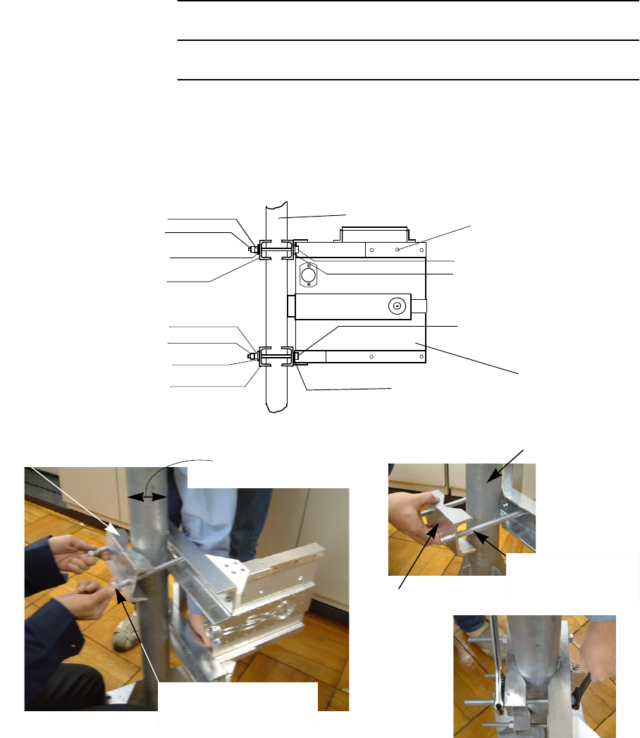
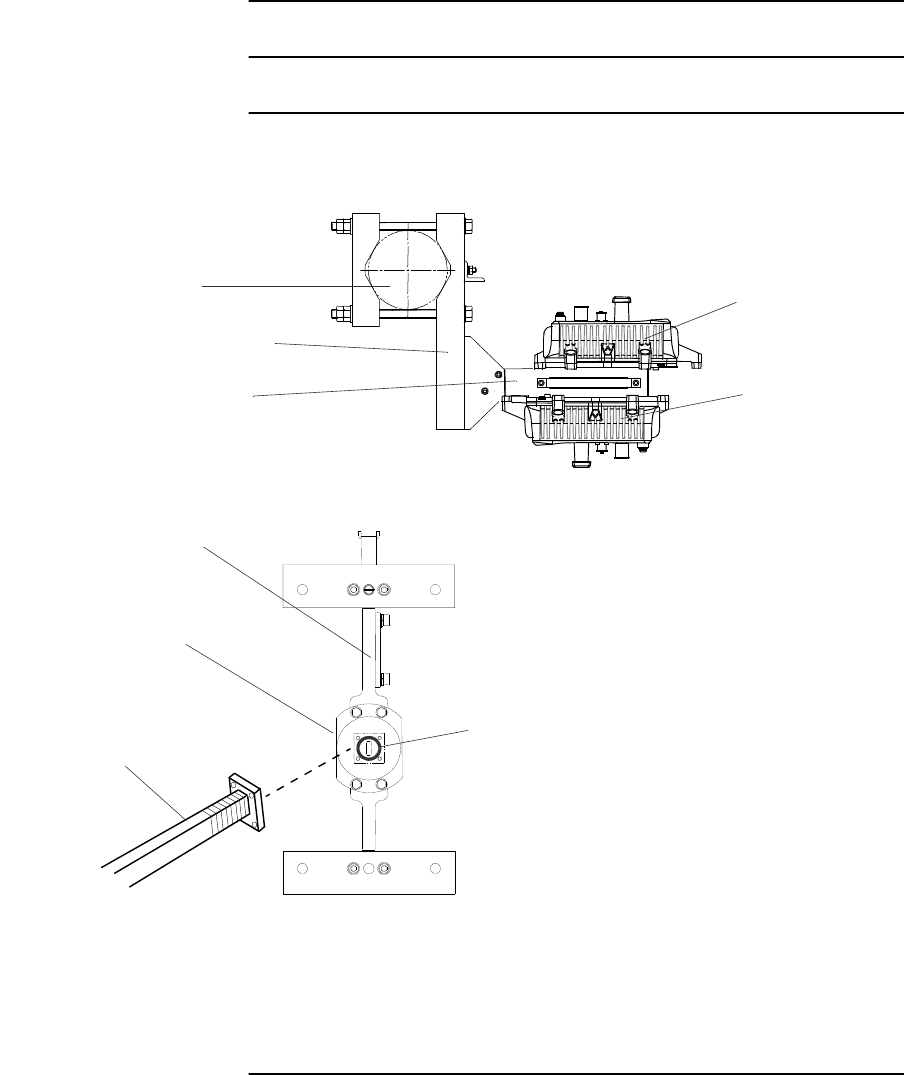
Chart 2-10 11-38 GHz Band TRP Mounting with HYB
(Waveguide Connection)
Step Procedure
WAVEGUIDE CONNECTION FOR 1+1 HYB
Note: * For 4 screws Type Bracket
1 Assemble the bracket and handle to the HYB.
Note: Tightening torque is 3.0 N·m ± 10%.
No. Parts Name Q’ty
1 Hybrid (Waveguide Flange Interface Type) 1
2Bracket 2
3 Handle 1
4 O-ring (for TRP) 2
5 O-ring (for Waveguide) 1
6M5 × 12 Hexagon Socket Head Cap Screw (SS) 10 (14)*
7M3 ×10 Hexagon Head Screw with Washer (×4) (SS) 4
M5 HEAD CAP SCREW
INSTALLATION ROI-S07045
2-54
Chart 2-10 (Cont’d)
Step Procedure
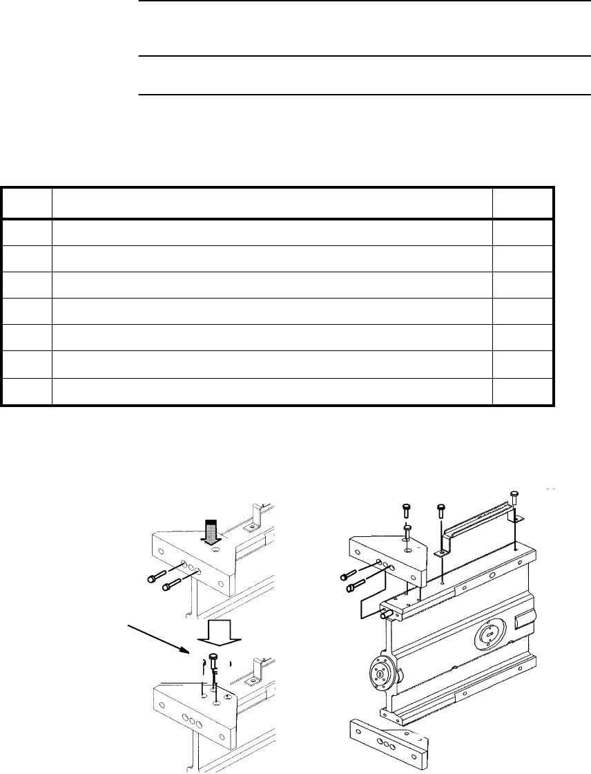
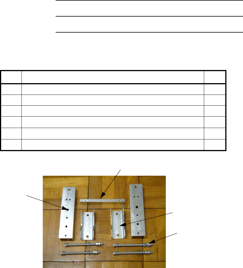
2 Assemble parts of the pole mounting bracket used to mount the
HYB,
No. Parts Name Q’ty
1 Mount Arm 2
2 Mount Holder 2
3Truss 1
4M12 × 200 Hexagon Head Screw with Nut (×2), Flat Washer (×2)(ST) 4
5M6 ×25 Hexagon Head Screw with Nut (x1), Flat Washer (×2), Spring Washer (SS) 4
6M6 × 35 Hexagon Head Screw with Nut (×2), Flat Washer (×2)(SS) 4
MOUNT ARM
TRUSS
MOUNT HOLDER
M12 × 200 SCREW SET
ROI-S07045 INSTALLATION
2-55
Chart 2-10 (Cont’d)
Step Procedure
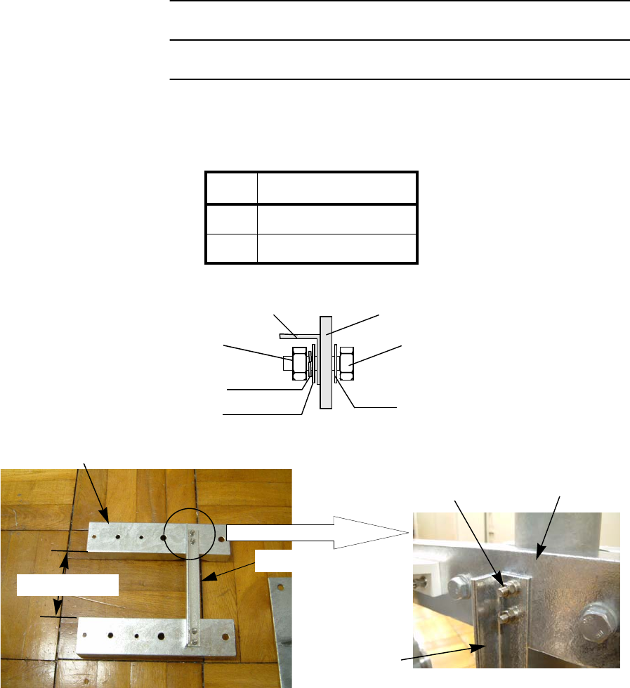
3 Screw the Mount Arm and the Truss with the M6 × 25 Screw,
Flat Washer (×2), Spring Washer (1), Nut, at four positions,
Tightening Torque
M6 4.0 N·m ± 10%
M12 47 N·m ± 10%
MOUNT ARM
MOUNT ARM
M6x25 Screw, Nut,
Flat Washer x 2
Spring Washer
TRUSS
TRUSS
Ab.144.3 mm
MOUNT ARM
TRUSS
M6 x 25 SCREW
FLAT WASHER
SPRING WASHER
FLAT WASHER
NUT
INSTALLATION ROI-S07045
2-56
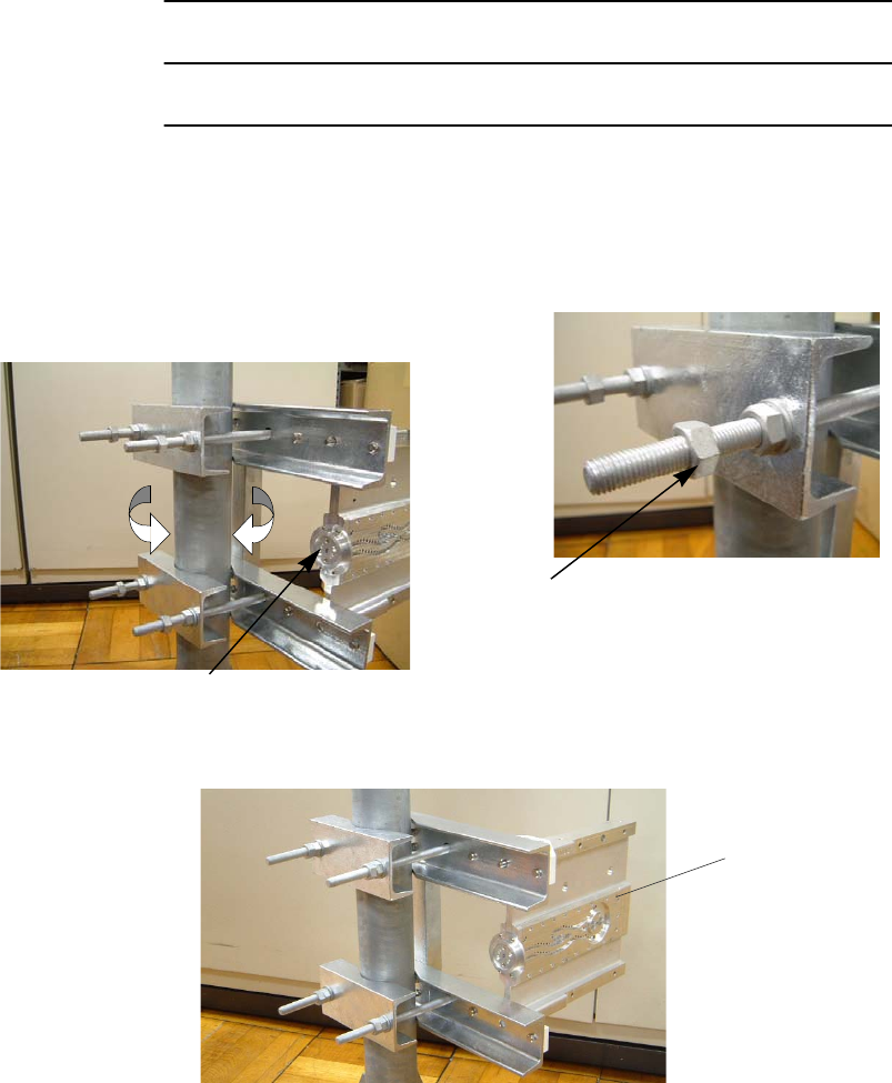
Chart 2-10 (Cont’d)
Step Procedure
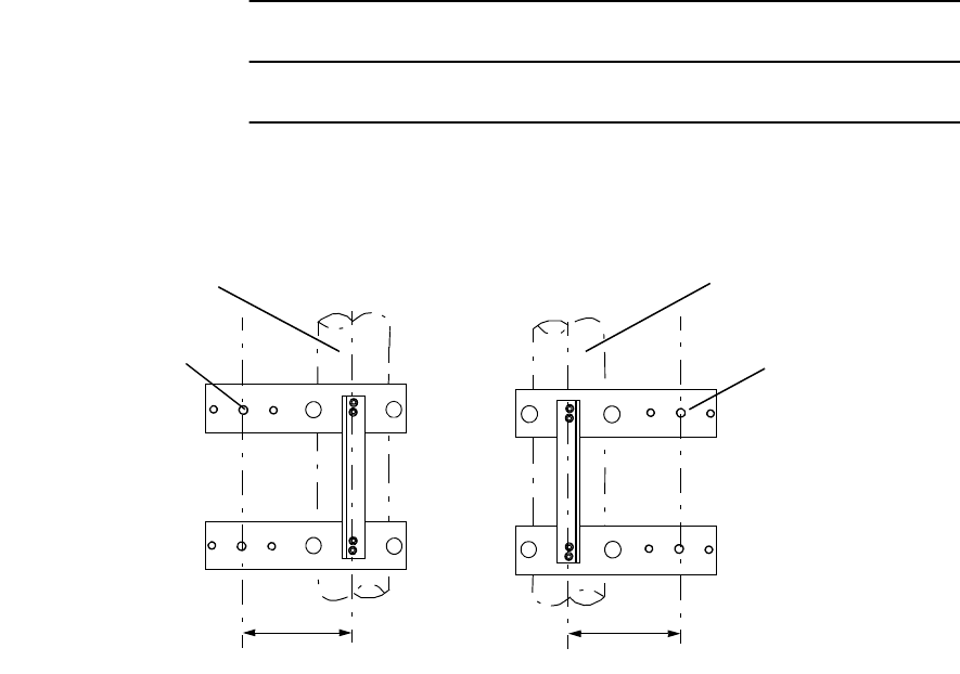
4 Determine centre off set,
5 Fit the guide pin of the HYB to the Guide Pin Hole of the Mount
Arm,
6 Install the HYB onto the bracket with the M6 × 35 Screw, Flat
Washer (×2), Nut (×2), at four positions,
MOUNTING PIPE
MOUNTING PIPE
CENTRE OFF SET
CENTRE OFF SET
GUIDE PIN HOLE
(HYB TOP)
GUIDE PIN HOLE
(HYB TOP)
ROI-S07045 INSTALLATION
2-57
Chart 2-10 (Cont’d)
Step Procedure
HYB
M6x35 SCREW,
NUT x 2
FLAT WASHER x 2
HYB TOP
M6x35 SCREW
FLAT WASHER
NUT
NUT
FLAT WASHER
HYB
GUIDE PIN
SHORT PLATE
Note: When either Main or Standby TRP is removed, attach the short plate over
the TRP port. Tightening torque is 3.0 N·m ± 10%.
TRP PORT SHORT PLATE
TRP PORT
MOUNT ARM
M6 x 35 SCREW
FLAT WASHER
FLAT WASHER
NUT
NUT
HYB
INSTALLATION ROI-S07045
2-58
Chart 2-10 (Cont’d)
Step Procedure
7 Install the HYB to the mounting pole using the M12 × 200
Screw, Flat Washer, Nut,
MOUNT HOLDER POLE DIAMETER
: ø50 to ø115mm
MOUNT HOLDER
M12x200 SCREW,
NUT x 2
FLAT WASHER x 2
M12x200 SCREW,
Nut x 2
FLAT WASHER x 2
MOUNT HOLDER
M12 x 200 SCREW
FLAT WASHER
FLAT WASHER
NUT
NUT
HYB
MOUNTING POLE
MOUNT HOLDER
FLAT WASHER
NUT
NUT
FLAT WASHER
M12 x 200 SCREW
MOUNTING POLE
GUIDE PIN HOLE
ROI-S07045 INSTALLATION
2-59
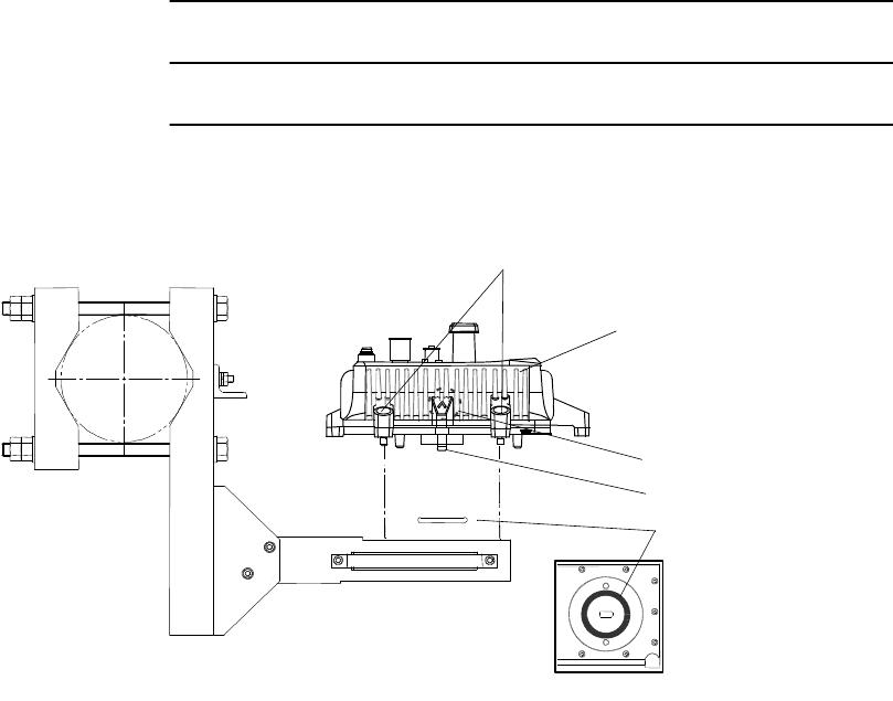
Chart 2-10 (Cont’d)
Step Procedure
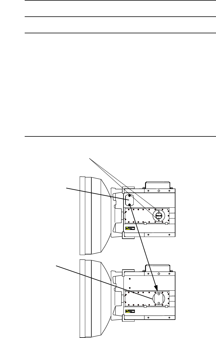
8 Adjust direction of the Bracket for Waveguide Port of the HYB
orientation,
9 Confirm the TRP Type, which is Master or Slave,
Caution: The same type must be installed onto the HYB.
Tighten double nut after orientation for
waveguide connection has been
decided.
Double Nut tightening
Determination of the attachment direction.
WAVEGUIDE PORT
HYB
INSTALLATION ROI-S07045
2-60
Chart 2-10 (Cont’d)
Step Procedure
10 Install the TRP onto the HYB,
Note: The TRP should be attached by turning the plate marked “V” up
position for both Main TRP and Standby TRP.
HEXAGON SOCKET HEAD CAP SCREW
MAIN TRP
O-RING
GUIDE PIN
MARK V TO TOP
(TOP VIEW)
(NHG TYPE)
(TRP NHG Type)
ROI-S07045 INSTALLATION
2-61
Chart 2-10 (Cont’d)
Step Procedure
Note: The TRP should be attached by turning the plate marked “V” up
position for both Main TRP and Standby TRP.
STANDBY TRP
O-RING
MARK V TO TOP
HEXAGON SOCKET
HEAD CAP SCREW
GUIDE PIN
(TRP NHG Type)
O-RING
STANDBY TRP
HEXAGON SOCKET
HEAD CAP SCREW
(TRP NHP Type)
MARK V TO TOP
GUIDE PIN
INSTALLATION ROI-S07045
2-62
Chart 2-10 (Cont’d)
Step Procedure
11 Connect the flexible waveguide (WG) to the TRP and fix the
waveguide to the TRP with four (4) bolts.
Note: Before connecting the WG to the antenna, confirm which
polarization is applied to the Master and Slave TRP.
Notes:1. Be careful not to damage the O-ring.
2. Tightening torque is 1.4 N·m ± 10%.
O-RING
WG PORT
HYB
MOUNTING POLE
POLE MOUNTING BRACKET
HYB
WG
MAIN TRP
STANDBY TRP
(TRP NHG Type)
ROI-S07045 INSTALLATION
2-63
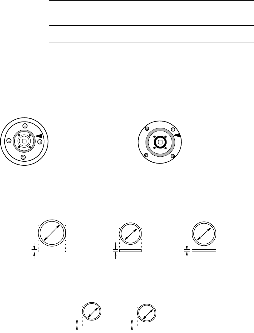
Chart 2-11 11-38 GHz Band TRP Mounting with OMT
(Antenna Direct Mounting)
Step Procedure
This section explains the installation of the OMT for XPIC system.
There are two types of O-rings for antenna mounting to the OMT
depending on the frequency band.
Caution: Do not apply silicon grease to O-ring.
Note: O-ring size is different with frequency band as follows:
POSITION OF LARGE
SIZE O-RING
FOR ANTENNA DIRECT MOUNTING
RFS ANTENNA
POSITION OF LARGE
SIZE O-RING
FOR ANTENNA DIRECT MOUNTING
ANDREW ANTENNA
32mm
35mm
LARGE SIZE O-RING FOR ANTENNA DIRECT MOUNTING
38 GHz BAND18/23 GHz BAND
4 mm
4 mm
40mm
11 GHz BAND
4 mm
18/23 GHz BAND 38 GHz BAND
15.6mm
SMALL SIZE O-RING FOR WAVEGUIDE CONNECTION
10.8mm
1.8 mm
1.8 mm

INSTALLATION ROI-S07045
2-64
Chart 2-11 (Cont’d)
Step Procedure
For the antenna direct mounting of the TRP, following OMT is used in the
XPIC system.
Caution: 1. For connecting the OMT to the antenna, the circular
type waveguide flange of the antenna is applied to the
XPIC system. When the V/H flange is mounted to the
antenna, it must be changed to a circular type.
2. When mounting the TRP to the OMT, confirm the
polarization for Main Master and SUB Master TRP. The
installation of the corresponding TRPs in the opposite
station must have the same polarization in order to
make into line Main Master and SUB Master
MODEMs.
FREQUENCY
BAND (GHz) FREQUENCY
RANGE (GHz)
INTERFACE WG
INNER DIA.(mm)
(ANT Side)
INTERFACE
(TRP Side)
11 10.4 −11.7 18.0
NEC
Original
18 17.7 − 19.7 10.5
23 21.2 − 23.6 9.0
24(26) 24.25 − 26.5 8.0
38 37 − 39.5 5.5
ROI-S07045 INSTALLATION
2-65
Chart 2-11 (Cont’d)
Step Procedure
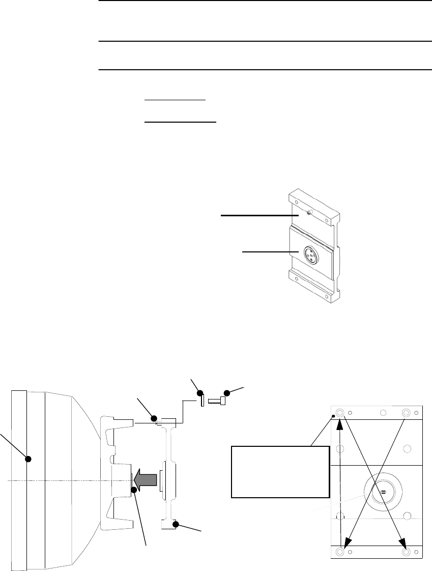
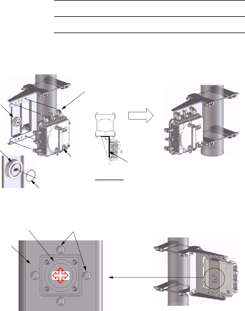
1 Fix the bracket and handle to the OMT.
2 Fix the OMT to the antenna by tightening them with M6 screws
(four locations),
Note: Tightening
torque is
3.0 N·m ± 10%.
M5 HEAD CAP SCREW
ANT
FLAT WASHER M6 M6 SCREWGUIDE PIN
O-ring
SHORT PLATE
MOVE THE
SHORT PLATE
SCREW
Note: Tightening torque is 4.0 N·m ± 10%. Note: Be careful not to damage the O-ring.
Note: Tightening torque is
3.0 N·m ± 10%.
INSTALLATION ROI-S07045
2-66
Chart 2-11 (Cont’d)
Step Procedure
3 Loosen the two screws and move the short plate if it is fixed to
the TRP port. (see figure in step 9),
4 Set the two TRPs to vertical polarization for OMT mounting. If
the guide pin behind the plate marked H is mounted, remove the
guide pin,
Note: The TRP should be attached by turning the plate marked
“V” up position for both Main Master TRP and SUB
Master TRP.
5 Insert the guide pin removed in step 4 behind the plate marked
V,
Note: Remove the protection metallic plate covering the
waveguide hole on TRP.
GUIDE PIN
PLATE MARKED WITH V
Main Master Sub Master
PLATE MARKED WITH V
UP
(TRP NHG/NHP Type)
ROI-S07045 INSTALLATION
2-67
Chart 2-11 (Cont’d)
Step Procedure
6 Insert the O-rings to the two TRP ports of the OMT (see figure
in step 9),
7 Insert the guide pin into the hole of the OMT and set the
position of screws,
8 Confirm which polarization is applied to the Master TRP.
Check the indication of polarization on the upper side of OMT.
9 Fix the two TRPs with hex screws (four locations) using the
allen key wrench,
Note: Be careful not to damage the O-rings.
Main Master Sub Master
PLATE MARKED WITH V
UP
(TRP NHG2 Type)
GUIDE PIN
INSTALLATION ROI-S07045
2-68
Chart 2-11 (Cont’d)
Step Procedure
O-ring
TRP
O-ring
TRP
TRP
HEX SCREW
H
POLARIZATION
SIDE
V
POLARIZATION
SIDE
HEX SCREW
Note: Tightening torque is 4.0 N·m ± 10%.
(TRP NHG Type)
O-ring O-ring
TRP
V
POLARIZATION
SIDE
HEX SCREW
Note: Tightening torque is 4.0 N·m ± 10%.
(TRP NHP Type)
H
POLARIZATION
SIDE
TRP
TRP
HEX SCREW
ROI-S07045 INSTALLATION
2-69
Chart 2-11 (Cont’d)
Step Procedure
Cautions: 1. Tighten all screws with lighter torque at first, then full
torque as specified.
2. When either TRP is demounting for TRP replacing or
other reasons, fix the attached short plate to the
demounted port of the OMT to avoid leaking of RF
power from the OMT and for waterproof.
3. To avoid occurrence of bit errors due to microphonic
properties, when installing the SUB Master TRP, protect
the Main Master TRP from mechanical knocks.
FIXED SHORT
PLATE TO THE TRP
PORT
FIXING HOLE FOR
SHORT PLATE
SHORT
PLATE
Note: Tightening torque is
3.0 N·m ± 10%.
INSTALLATION ROI-S07045
2-70
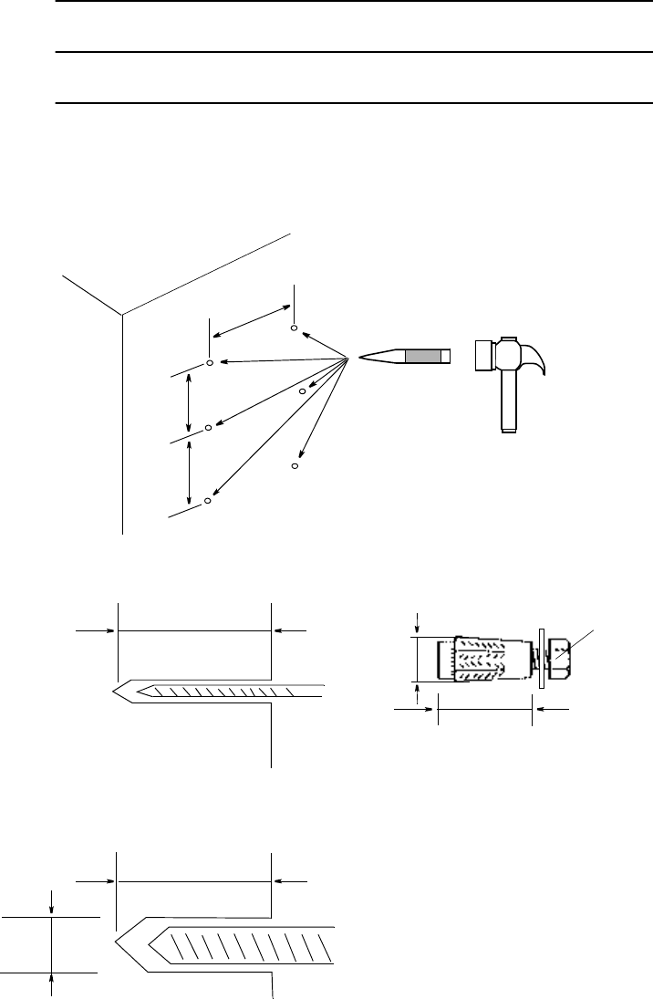
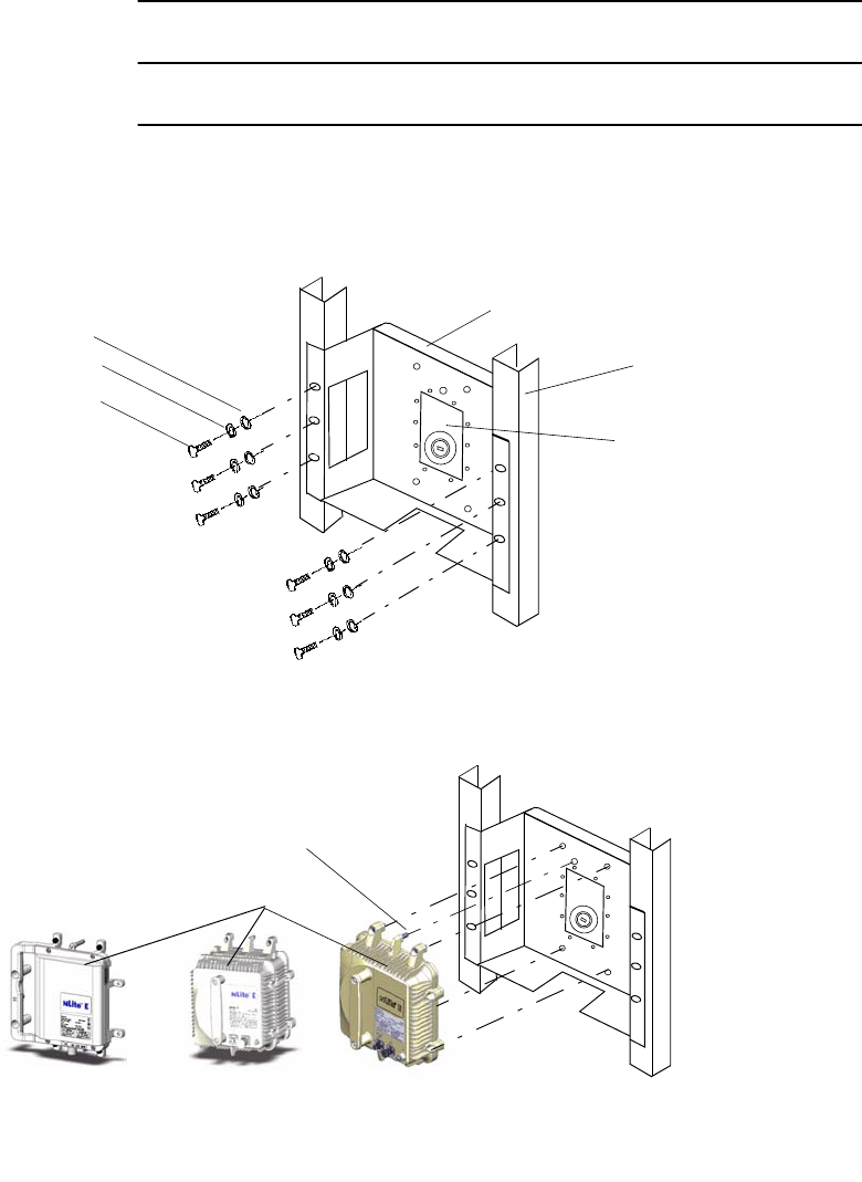
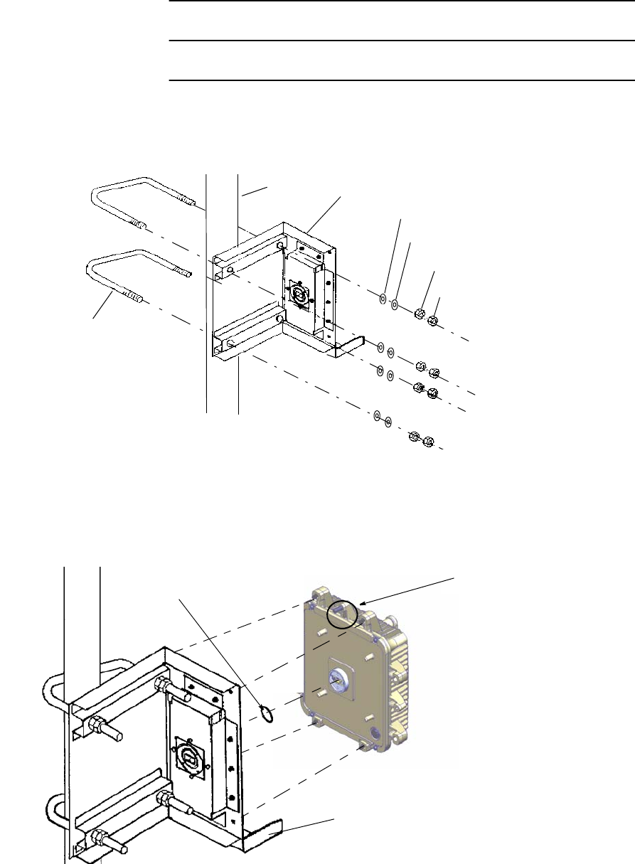
2.5.2 TRP Wall Mounting
For the antenna direct mounting type TRP, wall mounting installation is
explained in following procedure.
Chart 2-12 TRP Wall Mounting
Step Procedure
1 Using a center punch and hammer, mark the drilling holes for
the TRP wall mount bracket. Dimensions are shown below.
2 Using an electric drill for concrete, drill the guide holes,
3 Change the concrete drill to enlarge the holes and drill the
anchor bolt holes,
220
100
100
Unit : mm
WALL
L
L
D
M10
L
D
ROI-S07045 INSTALLATION
2-71
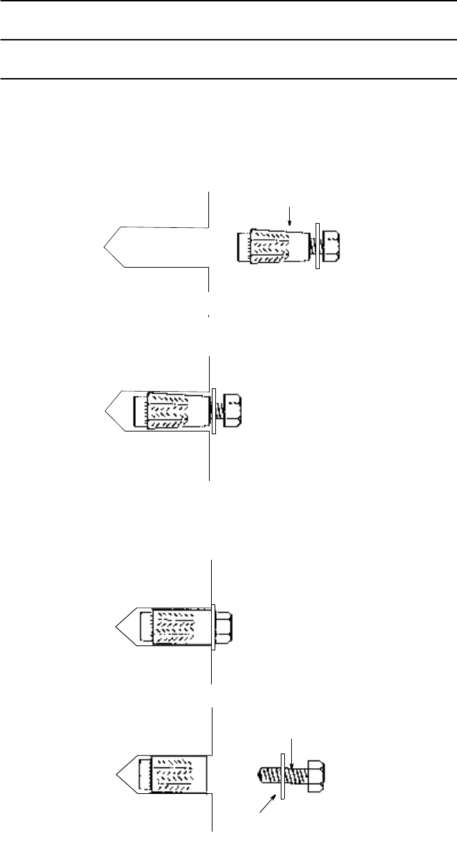
Chart 2-12 (Cont’d)
Step Procedure
4 Remove debris from the specified hole and insert a plug-bolt
into it,
6 Tighten hardly the bolt using a wrench or monkey wrench,
Note: Anchor bolts of M10 bolt shall be prepared by the
customer.
ANCHOR BOLT
5 Make sure to insert the plug-bolt fully,
BOLT
7 Loosen the bolt and remove it.
WASHER
INSTALLATION ROI-S07045
2-72
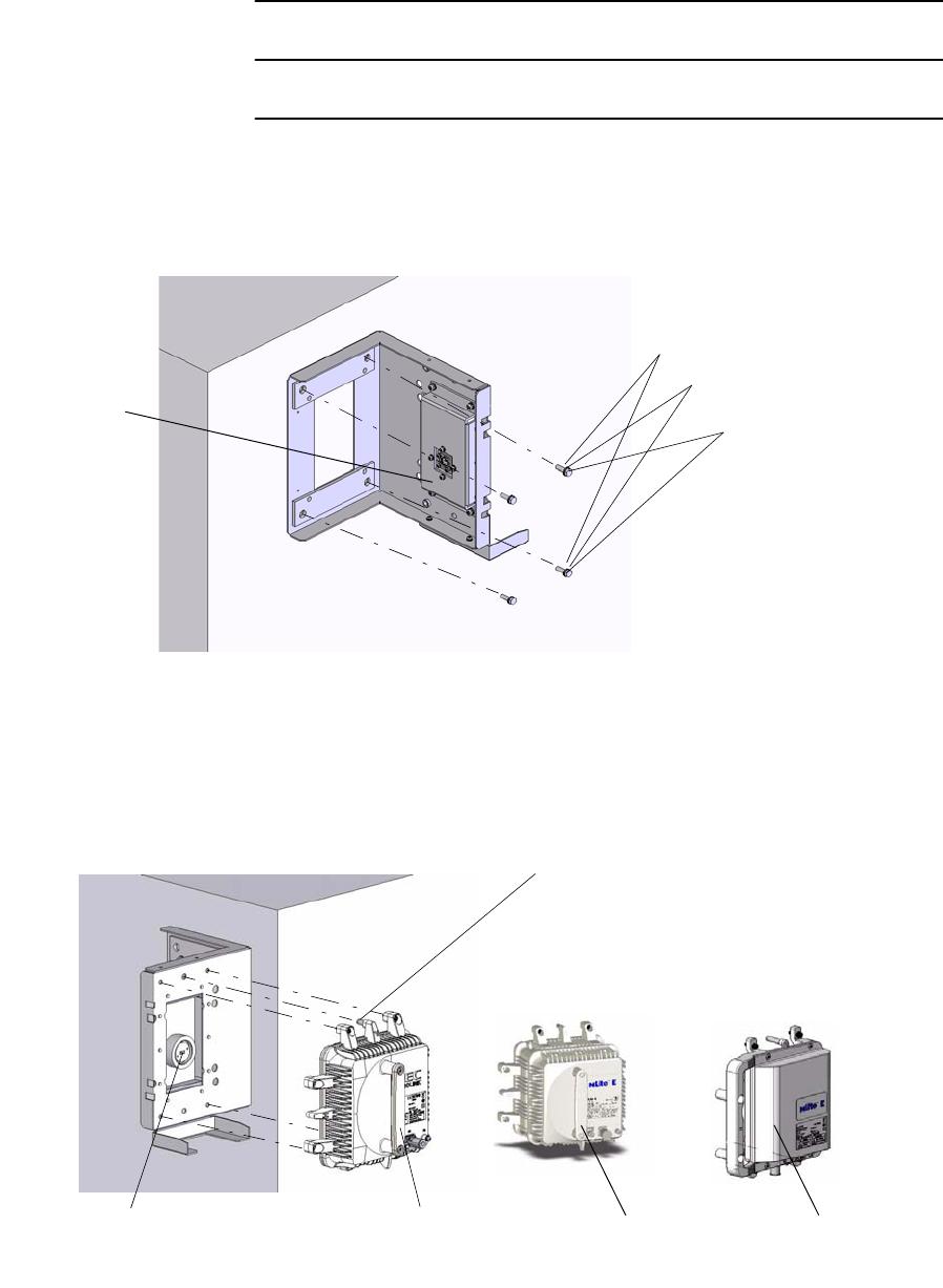
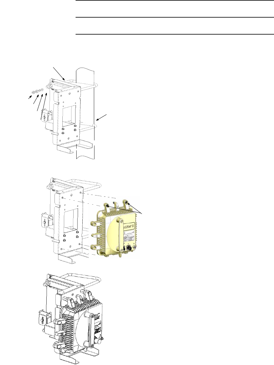
Chart 2-12 (Cont’d)
Step Procedure
8 Fix the TRP wall mounting bracket to the wall with the six bolts
(M6) of the anchor volt,
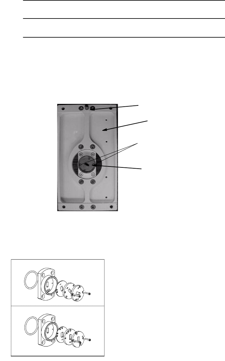
9 Mount the TRP onto the bracket and fix the TRP using the four
bolts (M6) on the TRP,
FLAT WASHER *
SPRING WASHER *
BOLT *
Note: * The BOLT, FLAT WASHER and SPRING WASHER are of
the Anchor bolt.
FRANGE
ADAPTOR
GUIDE PIN
(V)
TRANSDUCER
Note: The tightening torque is 4.0 N·m ± 10%.
(TRP NHG Type) (TRP NHP Type) (TRP NHG2 Type)
ROI-S07045 INSTALLATION
2-73
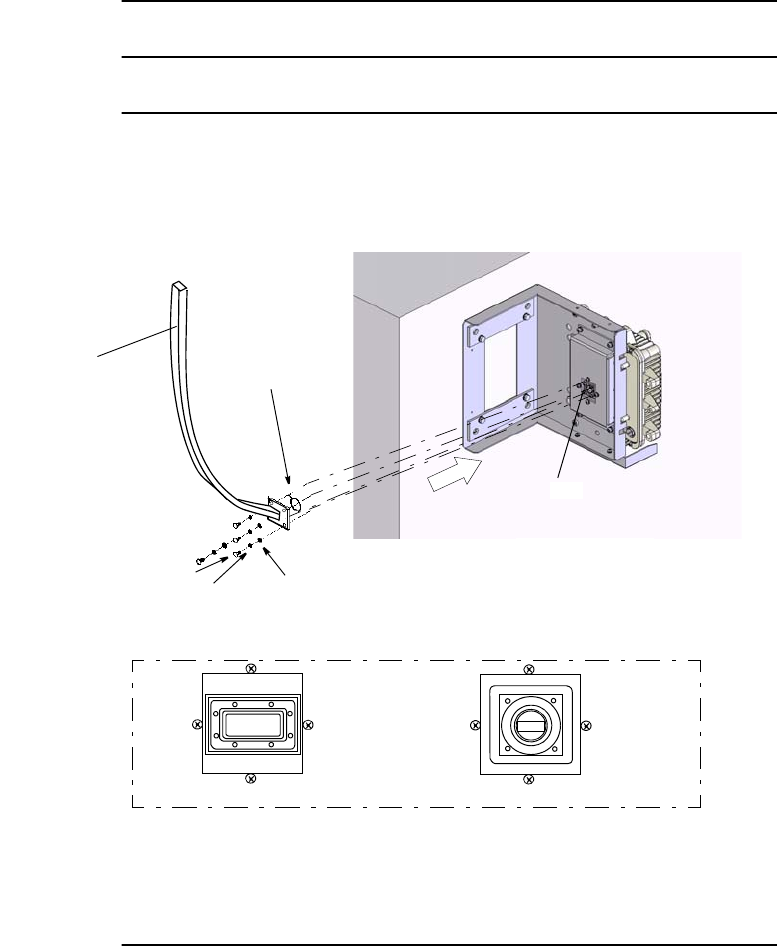
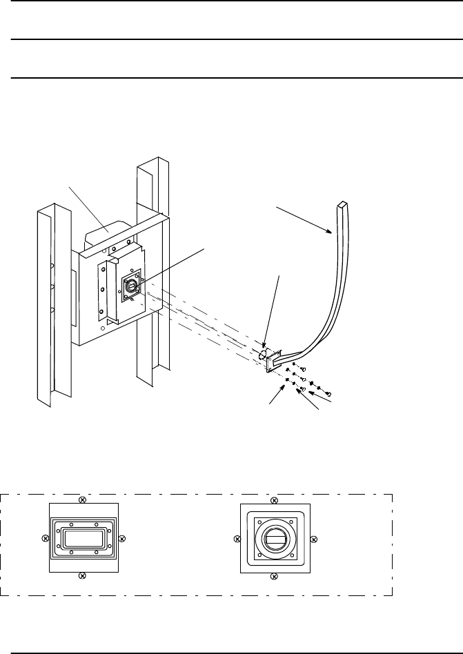
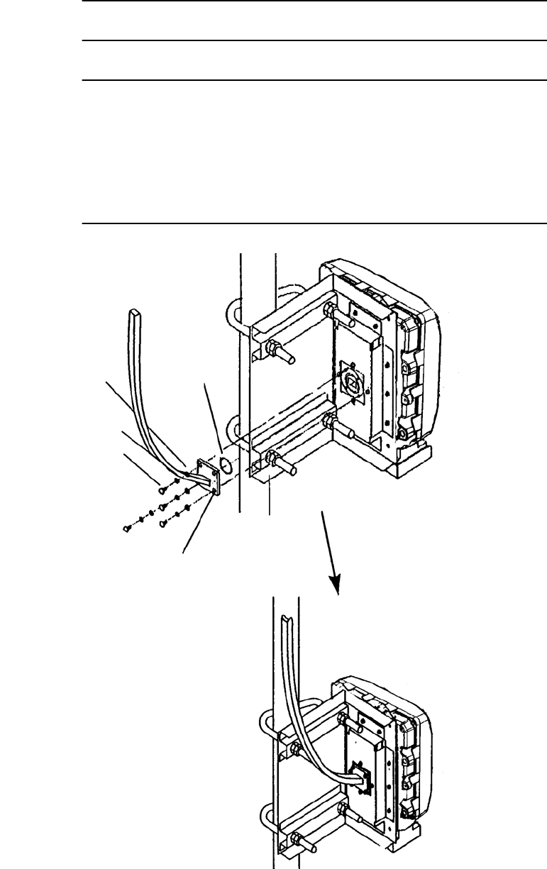
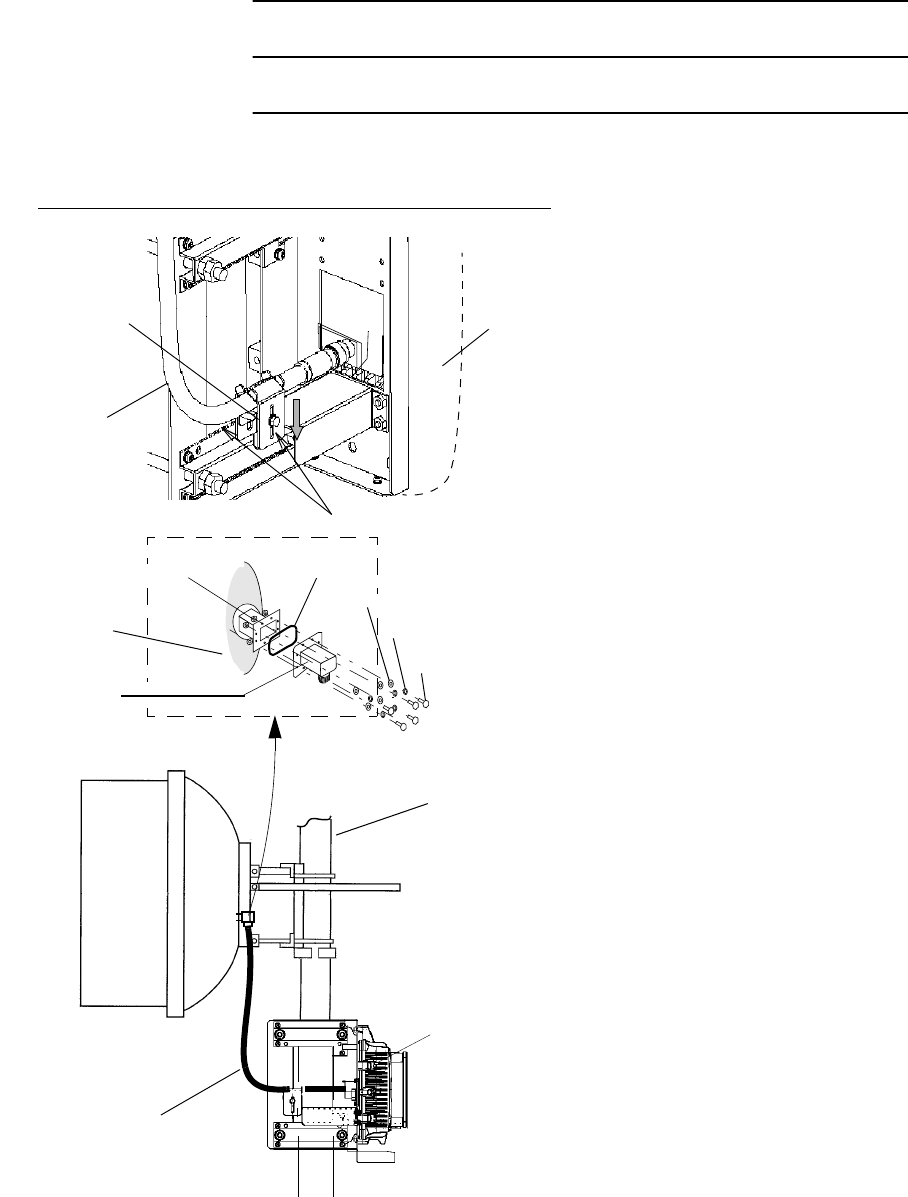
Chart 2-12 (Cont’d)
Step Procedure
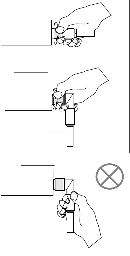
10 Connect the wave guide to the transducer for the TRP.
Refer to Chart 2-6 Feeder Connection for the wave guide
connection.
WASHER
O- RING
BOLT (M4)
SPRING WASHER
Note: Tightening torque is 1.4 N·m ± 10%. (up to 15 GHz)
Tightening torque is 0.6 N·m ± 10%. (18 GHz or higher)
Note: Be careful not to damage the O-ring.
(TRP NHG Type)
WAVEGUIDE
For 18-38 GHz
Details of A
For 11 GHz
A
INSTALLATION ROI-S07045
2-74
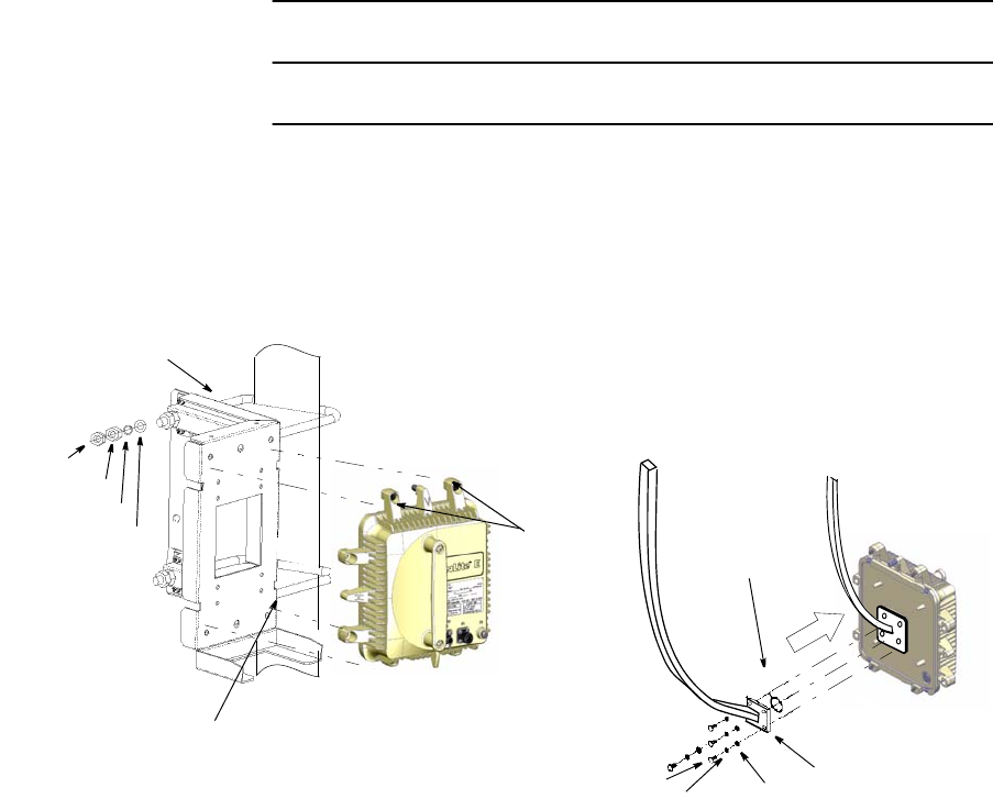
2.5.3 TRP Rack Mounting
For the antenna direct mounting type TRP, rack mounting installation is
explained in following procedure.
Chart 2-13 TRP Rack Mounting
Step Procedure
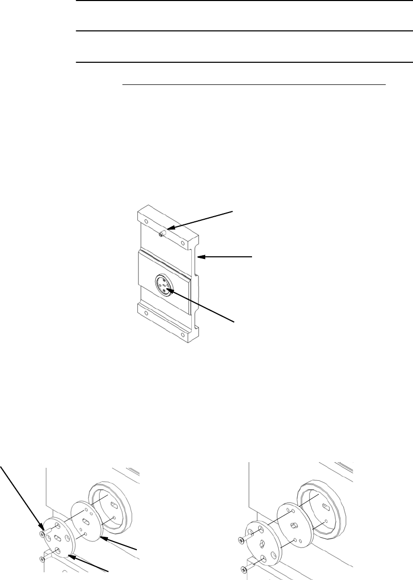
1 Fix the TRP rack mounting bracket into the 19-inch rack using
the six fixing bolts.
2 Mount the TRP onto the bracket and tighten the four fixing bolts
(M6) on the TRP,
BOLT
SPRING WASHER
FLAT WASHER
19-INCH RACK
TRP MOUNTING BRACKET
FRANGE
ADAPTOR
Note: The tightening torque is 4.0 N·m ± 10%.
TRP
GUIDE PIN
(NHP Type) (NHG Type)(NHG2 Type)
ROI-S07045 INSTALLATION
2-75
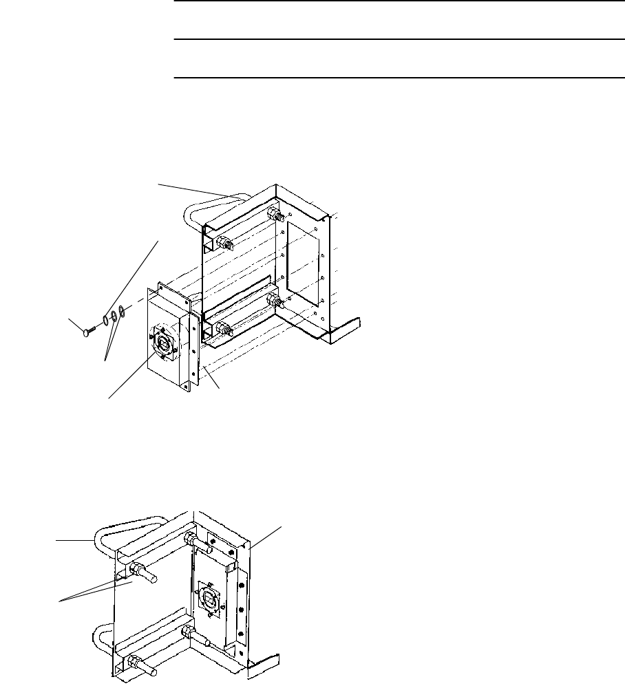
Chart 2-13 (Cont’d)
Step Procedure
3 Connect the wave guide to the transducer for the TRP.
Refer to Chart 2-6 Feeder Connection for the wave guide
connection.
WASHER
O- RING
WAVEGUIDE
BOLT (M4)
SPRING WASHER
TRP
Note: Be careful not to damage the O-ring.
A
For 13-38 GHz
Details of A
For 11 GHz
Note: Tightening torque is 1.4 N·m ±10% (up to 15 GHz).
Tightening torque is 0.6 N·m ±10% (18 GHz or higher).
INSTALLATION ROI-S07045
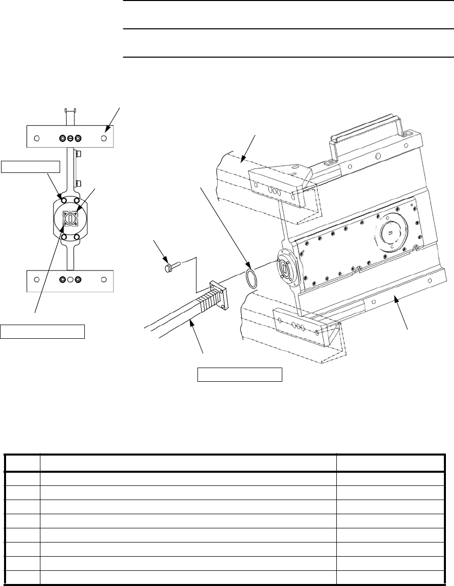
2-76
2.6 Feeder Connection
The connection method of the waveguide type TRP is described in
following procedure.
Chart 2-14 Wave Guide Connection
Step Procedure
1 Mount a waveguide to the TRP, fix the waveguide to the TRP
with four bolts.
Note: Being careful, not to damage the O-ring.
Notes: 1. Use suitable flange adapter between TRP and waveguide
depending on the waveguide type.
2. Connection of the waveguide is the same way as TRP is wall
mounted or 19-inch rack mounted.
The wave guide for the antenna direct mounting type TRP is flange
adapter is required. Refer to the following procedure.
THIN NUT
THICK NUT
SPRING WASHER
FLAT WASHER
U-BOLT
MOUNTING BRACKET
WASHER
O- RING
WAVEGUIDE
BOLT (M4)
SPRING WASHER
Tightening torque:
4.0 N·m ± 10%
M6
Note: Tightening torque is 1.4 N·m ±10% (up to 15 GHz).
Tightening torque is 0.6 N·m ±10% (18 GHz or higher).
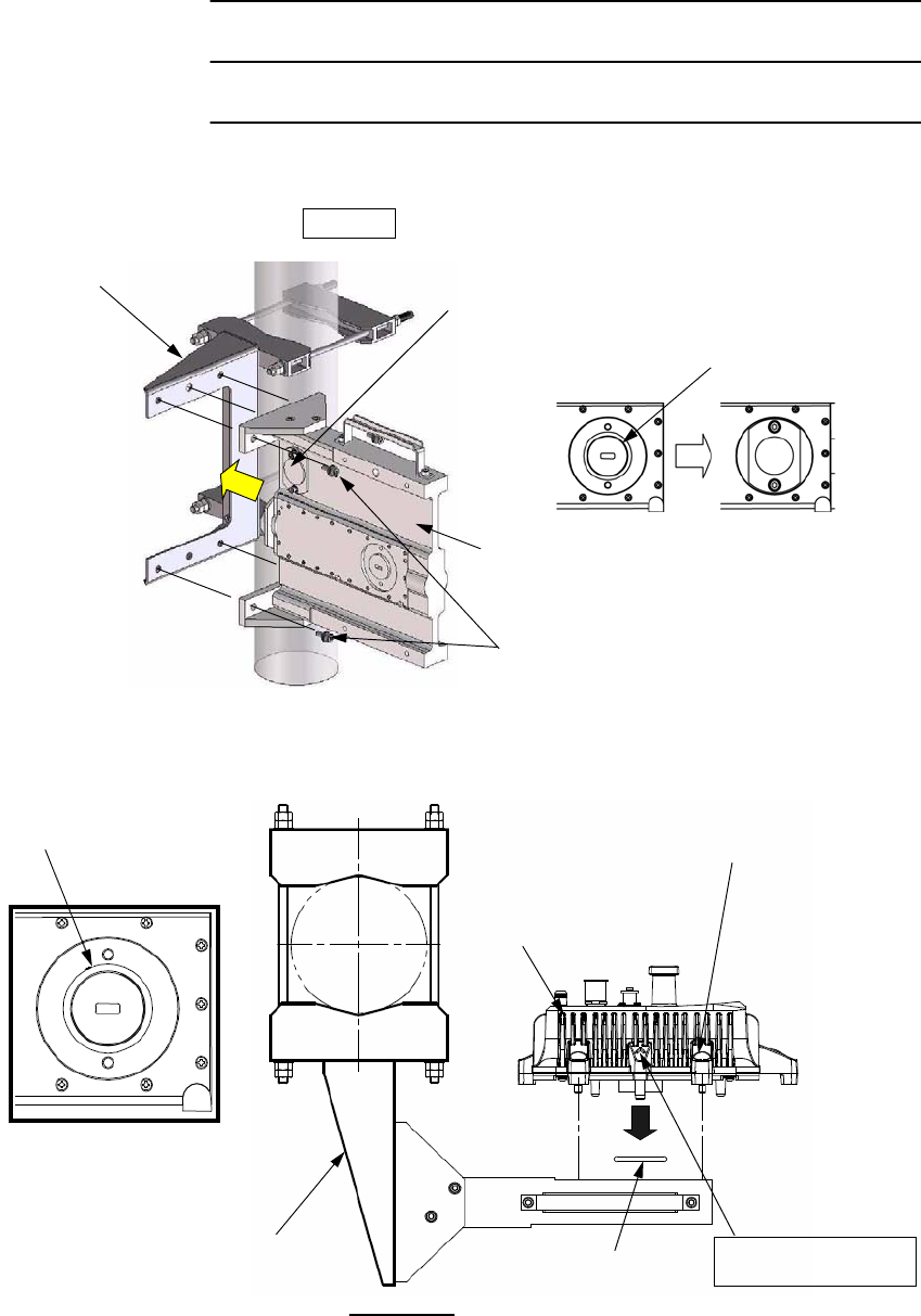
ROI-S07045 INSTALLATION
2-77
Chart 2-14 (Cont’d)
Step Procedure
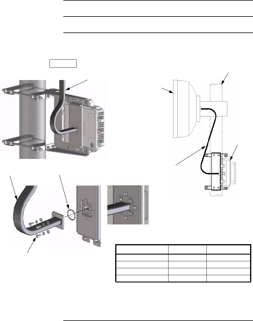
1 Mount the attachment with adapter to the TRP bracket using ten
bolts,
2 Loosen eight nuts and remove the two U-bolts from the TRP
bracket,
ATTACHMENT
SPRING WASHER
WASHER
TRP BRACKET
PBR ADAPTER
Note: Color of adapter is white.
BOLT (M5 ×10)
Tightening torque:
3.0 N·m ± 10%.
U-BOLT TRP BRACKET
NUT
INSTALLATION ROI-S07045
2-78
Chart 2-14 (Cont’d)
Step Procedure
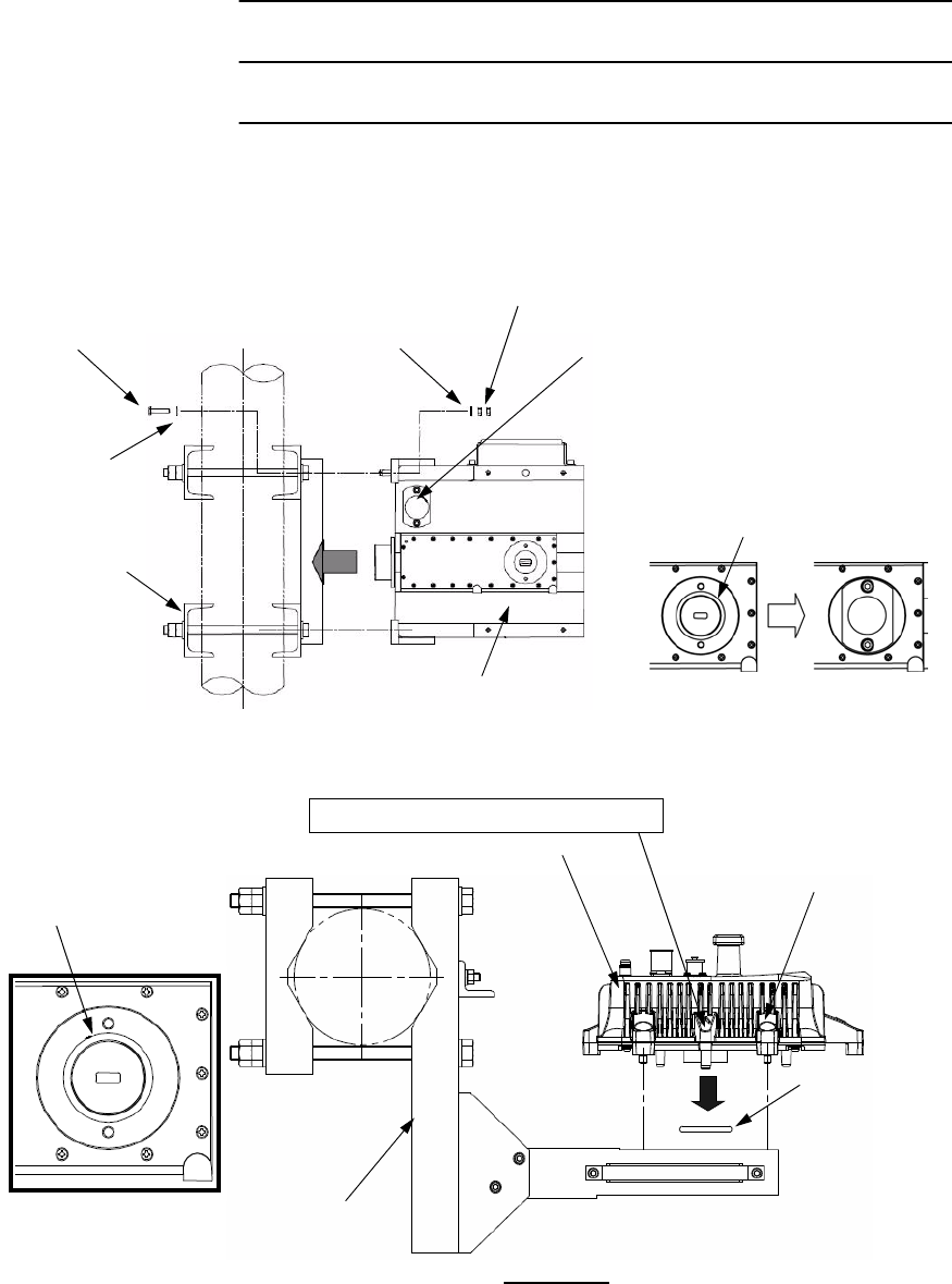
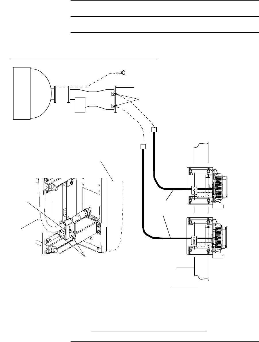
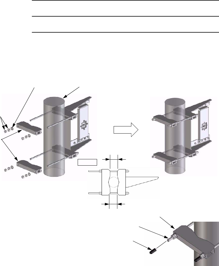
3 Mount the TRP bracket to the pole with two U-bolts,
Note: The diameter of the pole is from 48.5 to 114.5 millimeters.
4 Mount the TRP to the TRP bracket with attached four bolts
(Align the guide pins on the TRP and the guide holes on the
bracket),
Note: Be careful not to damage the O-ring.
TRP BRACKET
U-BOLT
POLE
FLAT WASHER
SPRING WASHER
THIN NUT (M10)
THICK NUT (M10)
Note: Tightening torque is 34.0 N·m ± 10%
TRP BRACKET
Antenna direct
mounting type TRP
with NEC special
flange.
O-RING
(Note)
GUIDE
PIN
Note: Tightening torque is 4.0 N·m ± 10%.
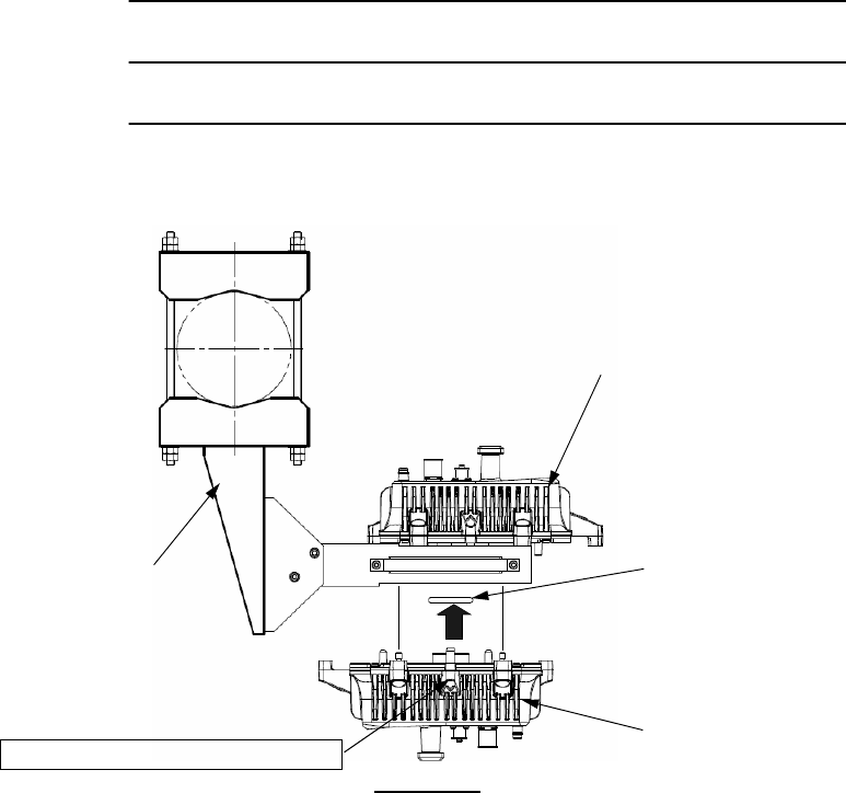
ROI-S07045 INSTALLATION
2-79
Chart 2-14 (Cont’d)
Step Procedure
5. Make sure that the TRP and the TRP bracket are fixed at
specified values.
6 Mount the waveguide to the TRP with four bolts.
Note: Be careful not to damage the O-ring attached to the PBR adapter.
BOLT (M4)
SPRING WASHER
WASHER O-RING
WAVEGUIDE
WITH PBR( ) FLANGE
Note: Tightening torque is 1.4 N·m ±10% (up to 15 GHz).
Tightening torque is 0.6 N·m ±10% (18 GHz or higher).
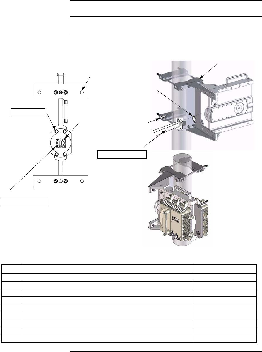
INSTALLATION ROI-S07045
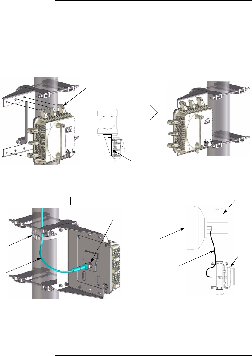
2-80
Chart 2-15 TRP Mounting for Connecting Coaxial Cable
Step Procedure
6 GHz TRP MOUNTING (Connecting Coaxial Cable)
1. Mount the bracket to the pole, point
to the opposite station and tighten it
with two U-bolts,
Note:The diameter of pole is from 48.5 to
114.5 millimeters.
THIN NUT
THICK NUT
SPRING WASHER
FLAT WASHER
U-BOLT
MOUNTING BRACKET
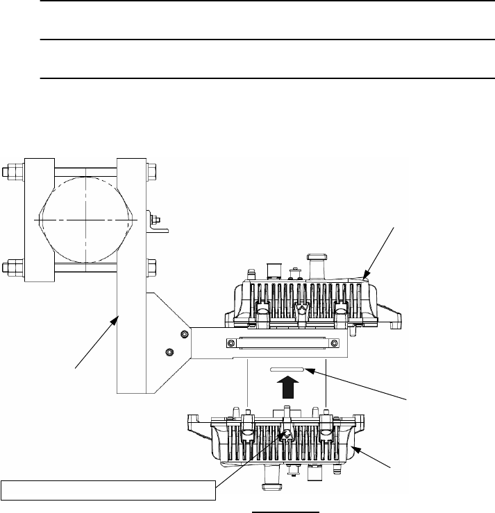
2. Mount the TRP on to the bracket and
tighten four bolts (M6) at upper and
lower parts of the TRP,
M6
3. Check that the TRP and the bracket
are fixed firmly,
Tightening torque: 4.0 N·m ± 10%
Tightening torque:
34.0 N·m ± 10%
Note: Being careful, tighten alternately and
gradually four screws.
ROI-S07045 INSTALLATION
2-81
Chart 2-15 (Cont’d)
Step Procedure
POLE
TRP
COAXIAL
CABLE
4. Connect the Coaxial cable to
the RF IN/OUT connector
of the TRP,
5. Down the cable fix bracket
to fix the Coaxial cable, then
tighten the two bolts,
6. Install the Coaxial cables
between the antenna and
TRP.
Note: Fix the coaxial cable to the pole or
member with cable hanger or cable
ties after antenna orientation has
been completed.
Caution: Wrap the coaxial cable
connection points with a self-
bonding tape for waterproof.
6 GHz TRP MOUNTING (Connecting Coaxial Cable)
COAXIAL
CABLE
TRP
BRACKET
TIGHTEN BOLTS (M5)
Note: Tightening torque is 3.0 N·m± 10%
O-RING
ANTENNA
WASHER
SPRING WASHER
BOLT (M4)
TRANSDUCER
NUT
(When the wave guide flange is
provided to the antenna port, fit
the transducer with eight bolts.)
Note: Tightening torque is 3.0 N·m ±10% (6 GHz).
INSTALLATION ROI-S07045
2-82
Caution: When connecting the IF cable to the
TRP, tighten the N-male connector
with engage connector nut only using
fingers and holding the cable with
another hand.
Tighten the engage connector nut
only for the L-angle connector also.
(Tightening Torque: 0.7 to 1.2 N•m
(7 to 12 kg•cm))
TRP
TRP
IF CABLE
IF CABLE
TRP
IF CABLE
Straight Type
L-Angle Type
L Angle Type
Caution: If rotate other parts of the L-angle
connector as illustrated left, it can
cause connector damage.
ROI-S07045 INSTALLATION
2-83
Chart 2-15 (Cont’d)
Step Procedure
POLE
No.1 TRP
No.2 TRP
HYB/COUPLER
BOLT
ANT
N-Type *
COAXIAL
CABLE*
Note: *:When coaxial cable with SMA connector is
used, the connectors are supplied by NEC.
USING HYB/COUOPLER FOR 1+1 SYSTEM
SIDE VIEW
Caution: Wrap the coaxial cable connection points
with a self-bonding tape for waterproof.
COAXIAL
CABLE
TRP
BRACKET
TIGHTEN BOLTS (M5)
6 GHz TRP MOUNTING (Connecting Coaxial Cable)
Note: Tightening torque is 3.0 N·m± 10%
INSTALLATION ROI-S07045
2-84
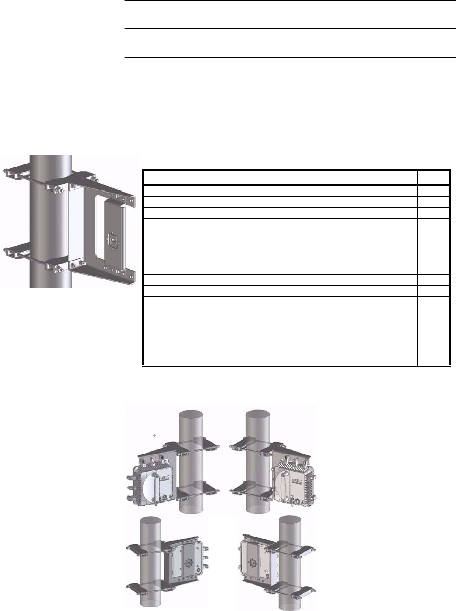
Chart 2-16 TRP Mounting for Connecting Coaxial Cable
or Waveguide
Step Procedure
6 GHz TRP MOUNTING BRACKET INSTALLATION
This Mounting Bracket is designed in order to install 6 GHz TRP with N-
type connector or Waveguide interface to a pole. The diameter of the pole
is from 48.5 to 114.3 millimeters.
Note: SS: Stainless Steel
Note: Tightening torque is 4 N·m ±10% (M6 Screw).
Tightening torque is 11 N·m ±10% (M8 Screw).
Mounting Bracket Parts List
Item Description Q’ty
1Bracket 1
2 Holder-1 (with two M6 taps) 2
3 Holder-2 2
4 M8 Stud Bolt (SS) 4
5 M8 Hexagon Nut (SS) 20
6 M8 Flat Washer (SS) 8
7 M6×16 Hexagon Socket Head Screw (SS) 4
8 M6 Spring lock Washer (SS) 4
9 M6 Flat Washer (SS) 4
10 Cap 4
11 Band (Cable Clamp) 2
Mounting Bracket
Standard Installation Reverse Installation
ROI-S07045 INSTALLATION
2-85
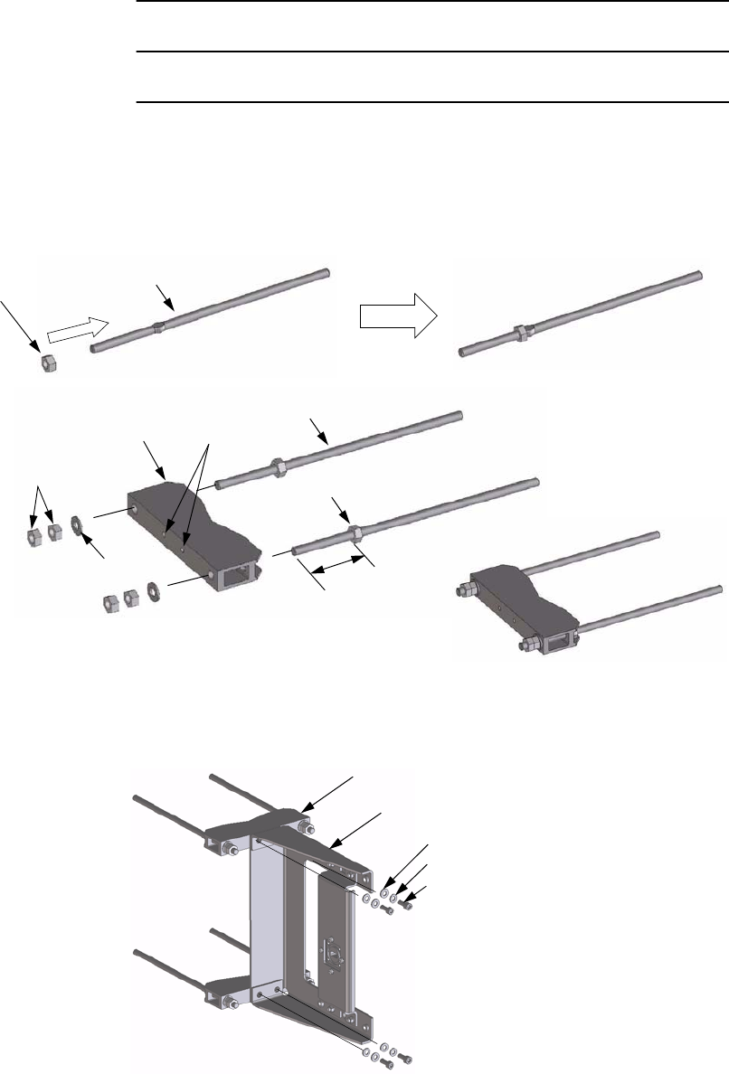
Chart 2-16 (Cont’d)
Step Procedure
1 A nut is assembled to a stud bolt until a nut has come to a
complete stop,
2 Fix the two Holder-1 to the Bracket at four bolts,
Stud Bolt M8
Hexagon Nut M8
Hexagon Nut M8 (4 ea)
Stud Bolt M8 (2 ea)
Fixed Nut
Approx. 56 mm
Holder-1
Flat Washer M8 (2 ea)
Note: Tightening torque is
11 N·m ±10%.
Assembly of the Holder-1 (2 sets)
2 Taps M6
Assembly of the Bracket
Holder-1 Assembly
Bracket
Flat Washer M6 (4 ea)
Spring Lock Washer M6 (4 ea)
Hexagon Socket Head Screw M6×16 (4 ea)
Note: Tightening torque is 4 N·m ±10%.
INSTALLATION ROI-S07045
2-86
Chart 2-16 (Cont’d)
Step Procedure
3 Mount the Bracket to the pole, point to the opposite station and
tighten it with four Stud bolts,
Pole (φ 48.5 to 114.3 mm)
Flat Washer M8 (4 ea)
Hexagon Nuts M8 (8 ea)
Note: Tightening torque is
11 N·m ±10%.
Holder-2 (2 ea)
A = B
A
B
Installation to the Pole
Holder
Bolt End
Cap (4 ea)
Note: Since a bolt projects from a Holder when a pole
diameter is small, please attach the Cap to a
bolt end.
ROI-S07045 INSTALLATION
2-87
Chart 2-16 (Cont’d)
Step Procedure
4 Mount the TRP on to the Bracket and tighten four bolts (M6) at
upper and lower parts of the TRP,
5 Connect the Coaxial cable to the RF IN/OUT connector of the
TRP,
6 Install the Coaxial cables between the antenna and the TRP.
Notes:1. Fix the Coaxial cable to the pole or member with Band
(cable ties) after antenna orientation has been completed.
2. Wrap the Coaxial cable connection points with a self-
bonding tape for waterproof. (The self-bonding tape shall be
prepared by customer.)
Hexagon Socket Head Screw M6
Attachment of the TRP
Note: Tightening torque is
4 N·m ±10%.
Right Angle Side
TOP VIEW
Connection of the Coaxial CableExample
N-type Connector
Band
Coaxial
Cable
Antenna
Coaxial Cable
Pole
TRP
INSTALLATION ROI-S07045
2-88
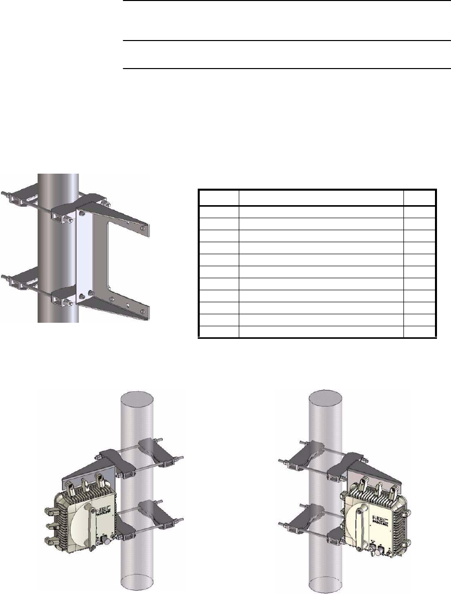
Chart 2-17 TRP Mounting for Connecting Waveguide
Step Procedure
10-38 GHz TRP MOUNTING BRACKET INSTALLATION
This Mounting Bracket is designed in order to install 11-38 GHz TRP with
antenna direct mount interface to a pole. The diameter of the pole is from
48.5 to 114.3 millimeters.
Note: SS: Stainless Steel
Note: Tightening torque is 4 N·m ±10% (M6 Screw).
Tightening torque is 12 N·m ±10% (M8 Screw).
Mounting Bracket Parts List
Item Description Q’ty
1 Bracket (with Adapter) 1
2 Holder-1 (with two M6 taps) 2
3 Holder-2 2
4 M8 Stud Bolt (SS) 4
5 M8 Hexagon Nut (SS) 20
6 M8 Flat Washer (SS) 8
7 M6×16 Hexagon Socket Head Screw (SS) 4
8 M6 Spring Lock Washer (SS) 4
9 M6 Flat Washer (SS) 4
10 Cap 4
11 O-Ring (for TRP) 1
12 O-Ring (for Waveguide) 1
13 Screw of Waveguide Connecting
for 10/11 GHz M4×14 Hexagon Head Screw with Washer (SS)
for 13/15 GHz M4×12 Hexagon Head Screw with Washer (SS)
for 18/23/26/28/32/38 GHz M3×10 Hexagon Head
Screw with Washer (SS)
8
4
4
Mounting Bracket
Standard Installation Reverse Installation
ROI-S07045 INSTALLATION
2-89
Chart 2-17 (Cont’d)
Step Procedure
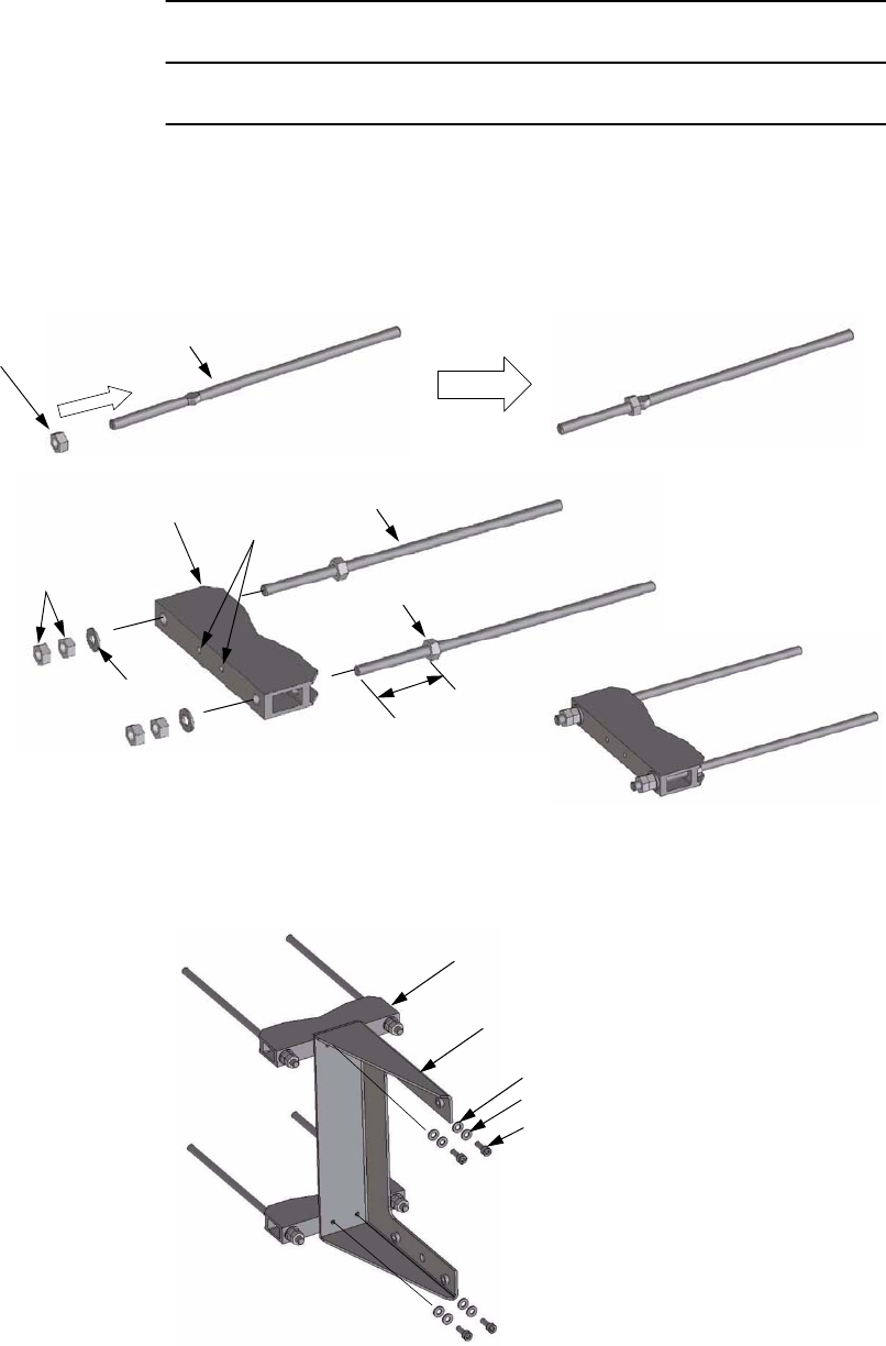
1 A nut is assembled to a stud bolt until a nut has come to a
complete stop,
2 Fix the two Holder-1 to the Bracket at four bolts,
Stud Bolt M8
Hexagon Nut M8
Hexagon Nut M8 (4 ea)
Stud Bolt M8 (2 ea)
Fixed Nut
Approx. 56 mm
Holder-1
Flat Washer M8 (2 ea)
Note: Tightening torque is
12 N·m ±10%.
Assembly of the Holder-1 (2 sets)
2 Taps M6
Assembly of the Bracket
Holder-1 Assembly
Bracket (with Adapter)
Flat Washer M6 (4 ea)
Spring Lock Washer M6 (4 ea)
Hexagon Socket Head Screw M6×16 (4 ea)
Note: Tightening torque is 4 N·m ±10%.
INSTALLATION ROI-S07045
2-90
Chart 2-17 (Cont’d)
Step Procedure
3 Mount the Bracket to the pole, point to the opposite station and
tighten it with four Stud bolts,
Pole (φ 48.5 to 114.3 mm)
Flat Washer M8 (4 ea)
Hexagon Nuts M8 (8 ea)
Note: Tightening torque is
12 N·m ±10%.
Holder-2 (2 ea)
A = B
A
B
Installation to the Pole
Holder
Bolt End
Cap (4 ea)
Note: Since a bolt projects from a Holder
when a pole diameter is small, please
attach the Cap to a bolt end.
ROI-S07045 INSTALLATION
2-91
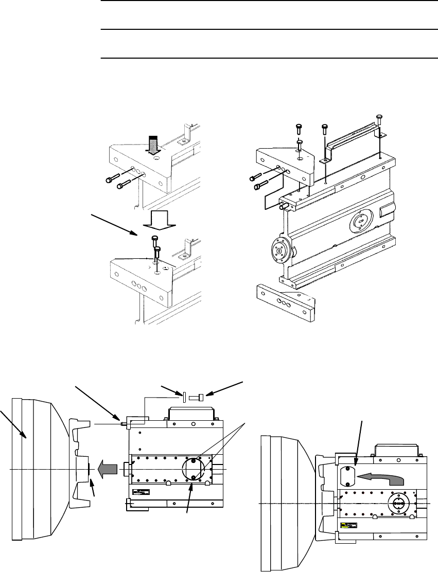
Chart 2-17 (Cont’d)
Step Procedure
4 Mount the TRP on to the Bracket and tighten four bolts (M6) at
upper and lower parts of the TRP. Please equip the terminal area
of TRP and Adapter with O-ring, and join together after that,
5 When the attachment screw of the TRP is hard, please loosen
the fixed four screw of adapter once,
6 Please adjust the position of adapter to compensate for
attachment of TRP. Then tighten four bolts (M6) of the TRP,
Hexagon Socket Head Screw M6
Attachment of the TRP
Note: Tightening torque is
4 N·m ±10%.
Right Angle Side
Adapter
TRP
Adapter
O-Ring (for TRP)
TOP VIEW
Loosen the Fixed Four Screws
Adapter
Bracket
INSTALLATION ROI-S07045
2-92
Chart 2-17 (Cont’d)
Step Procedure
7 Connect the waveguide to the adapter of the mounting bracket,
8 Install the waveguide between the antenna and the TRP.
Connection of the WaveguideExample
Flexible Waveguide
Antenna
Pole
TRP
Flexible Waveguide
Flexible Waveguide O-Ring (for Waveguide)
Screw of Waveguide
Connecting
Waveguide Flange Type
Frequency Band Adapter Waveguide
11 GHz PDR100 PDR100
18/23 GHz PBR220 UBR220
24(26) GHz PBR260 UBR260
38 GHz PBR320 UBR320
ROI-S07045 INSTALLATION
2-93
Chart 2-18 Hybrid combiner installation for dual
Polarized antenna
Step Procedure
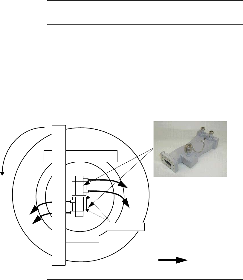
When you attach two Hybrids to one Dual pol. antenna, rotate the
antenna 90 degree counter clockwise, as shown below, to avoid hitting the
hybrids to the antenna pole and its structures if necessary.
WG Flange
To TRP
To TRP
Rotate counter
clockwise 90
degree
LOW LOSS Cable
INSTALLATION ROI-S07045
2-94
2.7 Cable Termination
In this section, list of tools and material and the method for cable
termination method are described. The following cables are described for
reference.
• D-sub connector (refer to Chart 2-19)*
• TNC-P connector of the L angle type for MDP (refer to Chart 2-
20)**
• N-P connector of the L angle type for TRP (KOMINE made) (refer to
Chart 2-21)**
• N-P connector of the L angle type for TRP (HIROSE made) (refer to
Chart 2-22)**
• N-P connector of the straight type for TRP (HIROSE made) (refer to
Chart 2-23)**
• N-P connector of the straight type for TRP (KOMINE made) (refer to
Chart 2-24)**
• Molex 5557-04R connector (refer to Chart 2-25)
• BNC connector soldering type (refer to Chart 2-26)
• BNC connector crimping type (refer to Chart 2-27)
D-Sub High Density Crimp Contacts assembly (refer to Chart 2-28)*
Notes: 1. *Use D-sub connectors of less than 16 mm in height as
illustrated below.
2. *Use D-sub 44-pins connector for the CTRL of less than 57
mm in width as illustrated below.
3. **In 1+1 system, the difference between the No.1 channel
IF cable length and the No.2 channel IF cable length should
be within 100m. (differential absolute delay time: within
500 ns).
Note: Use shielded cables which are connected to the D-Sub/RJ-
45 connector to suppress interference from affecting the
signal and to reduce electromagnetic radiation which may
interfere with other signal cables.
HEIGHT
D-SUB CONNECTOR
D-SUB 44 PIN CONNECTOR for the CTRL
WIDTH

ROI-S07045 INSTALLATION
2-95
The tools and materials summarized in Table 2-5 are necessary.
Table 2-5 Tools and Material List
No. NAME REMARKS
1 Soldering Iron
2Solder
3Knife
4 Measure/Ruler
5Wire Stripper
6 Adjustable Wrench
7 Hand Crimping Tool
CL250-0012-2/
CL250-0013-5 For D-Sub connector
57026-5000/
57027-5000 For Molex connector
09 99 000 0596/
09 99 000 0513 For D-Sub High density connector
INSTALLATION ROI-S07045
2-96
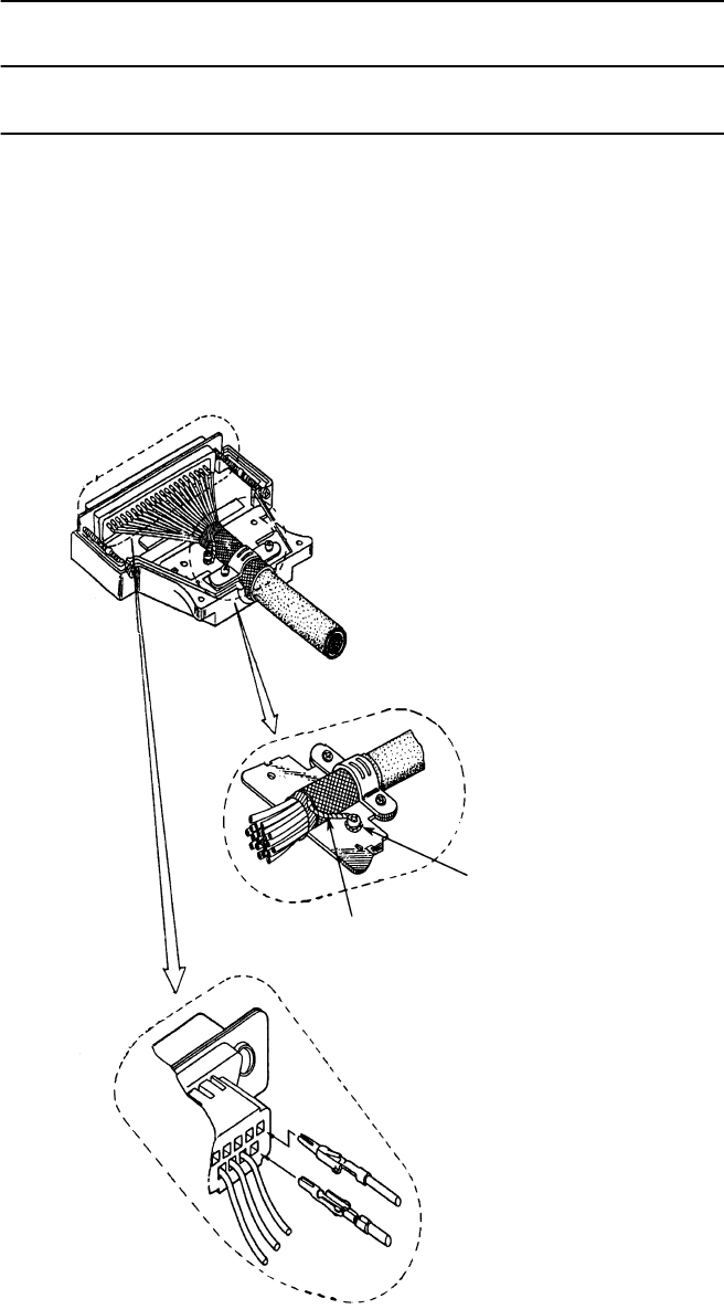
Chart 2-19 Terminating Supervisory Cables with D-Sub
Connector
Step Procedure
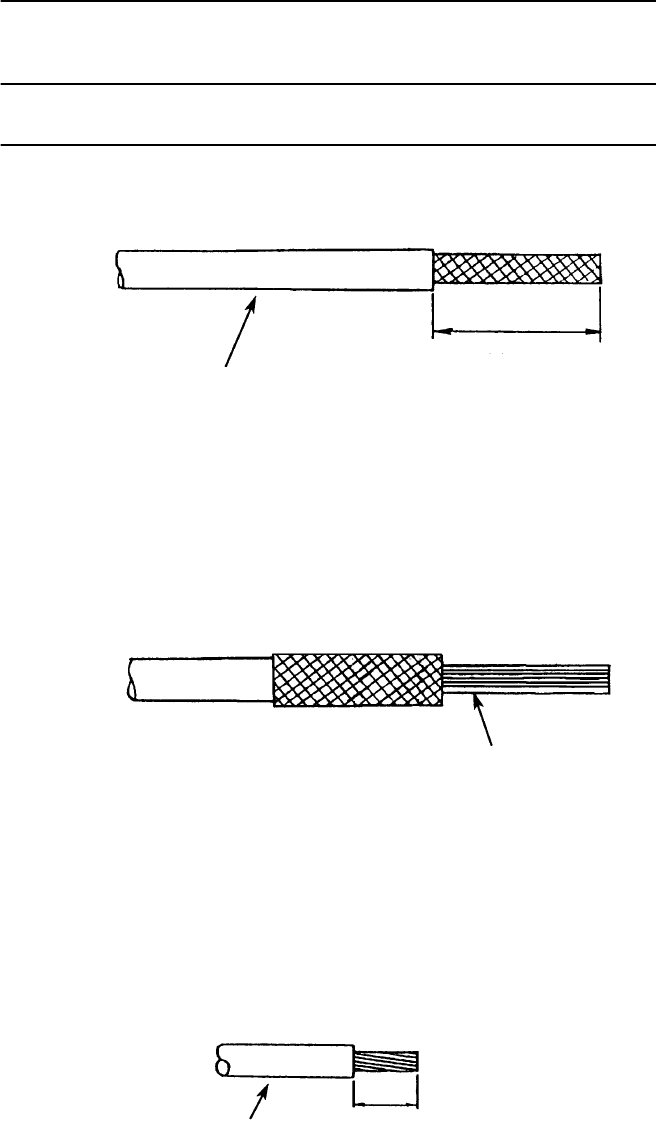
1 Strip back the cable sheath, taking care not to damage the
braided shield.
2 Fold back the braided shield (do not separate the strands) and
trim it as shown.
3 Remove 4 mm of insulation from the end of the wire.
CONFORMABLE
WIRE SOCKET CONTACT
AWG#20-24: CD-PC-111
AWG#24-28: CD-PC-121
50 mm
CABLE
Note: Use shielded cables which are connected to the D-Sub
connector to suppress interference from affecting the
signal and to reduce electromagnetic radiation which may
interfere with other signal cables.
WIRE
WIRE 4 mm
ROI-S07045 INSTALLATION
2-97
Chart 2-19 (Cont’d)
Step Procedure
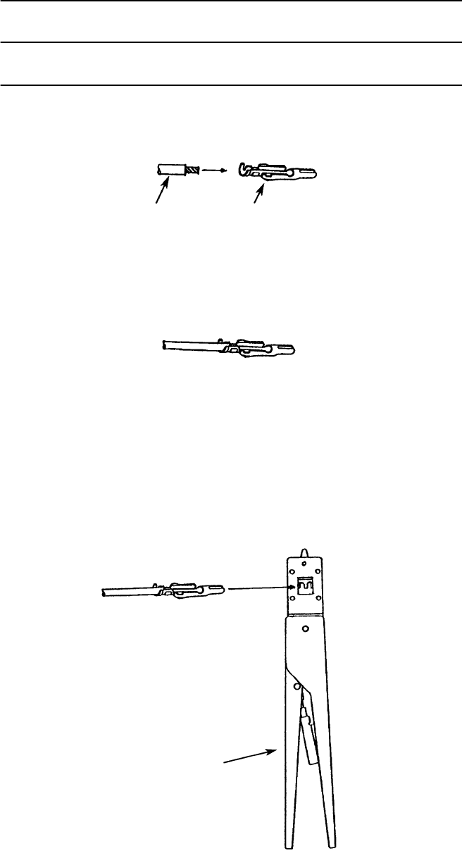
4 Insert the cable into the socket contact.
5 The cable should be fitted so that insulation and bare wire are
arranged as shown.
6 Insert the socket contact into the hand crimping tool.
CONFORMING
WIRE SOCKET CONTACT
AWG#20-24: TC-CD-111
AWG#24-28: TC-CD-121
WIRE SOCKET CONTACT
HAND CRIMPING TOOL
(HRS TC-CD-111/TC-CD-121)
INSTALLATION ROI-S07045
2-98
Chart 2-19 (Cont’d)
Step Procedure
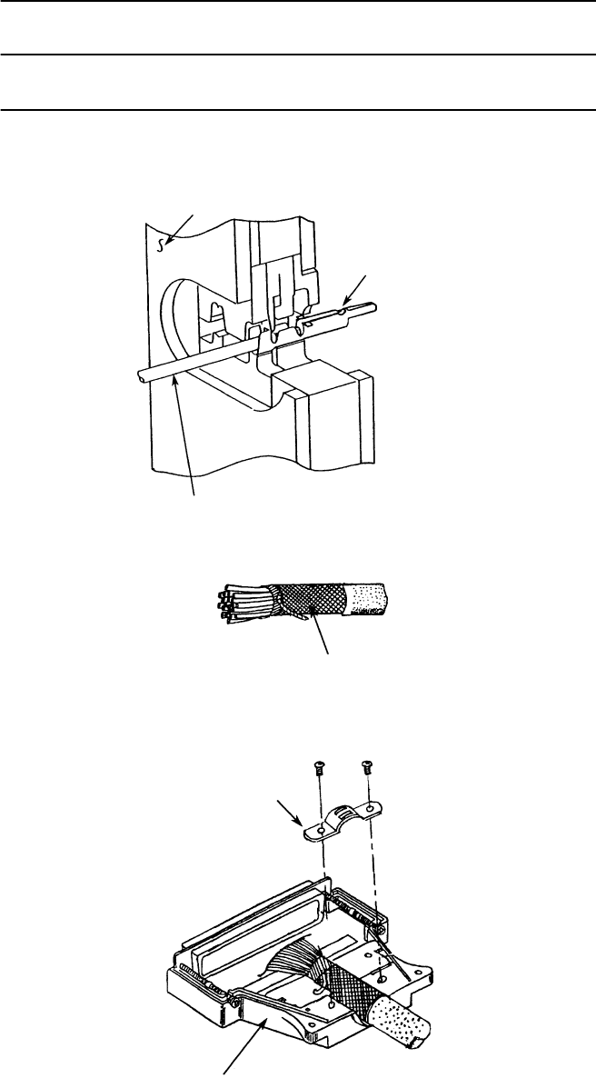
7 Recheck that the wire position is as shown in step 5 before
crimping the socket contact (see illustration below).
8 Wind the metallic shield tape over the braided shield.
9 Set the cable into the plug case as shown in figure below. Then,
fix the cable using the cable clamper and two screws.
WIRE SIDE
SOCKET CONTACT
WIRE
METALLIC SHIELD TAPE
CABLE CLAMPER
PLUG CASE
ROI-S07045 INSTALLATION
2-99
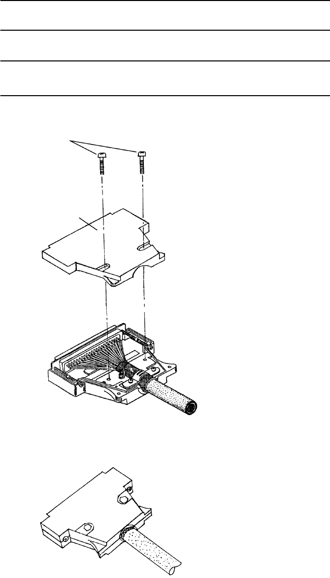
Chart 2-19 (Cont’d)
Step Procedure
10 Referring to circle A, fix the drain wire with screw.
11 Referring to circle B, insert each wire to the specified position
(Refer Interface Terminals and Jacks for MDP in Section II
OPERATING EQUIPMENT.). Insert the socket contacts into
the upper and lower row positions while taking care that the
socket contacts are inserted the right way.
CIRCLE A
SCREW
DRAIN WIRE
CIRCLE B
INSTALLATION ROI-S07045
2-100
Chart 2-19 (Cont’d)
Step Procedure
12 Fix the plug case with two screws, as shown in the figure.
SCREW
PLUG CASE
ROI-S07045 INSTALLATION
2-101
Chart 2-20 Terminating IF Coaxial Cable with TNC-P
Connector (L Angle Type) (HIROSE made)
used for MDP IF IN/OUT
Step Procedure
Note: It is recommended that TNC (Male) L-angle connector for the
8D-FB IF cable is used to connect it to the MDP. When the N
(Male) straight connector is attached to the 5D-FB or 10D-FB
IF cable, use of the TNC (Male) - N (Female) (NJ-TNCP-LA)
L-angle adapter is needed.
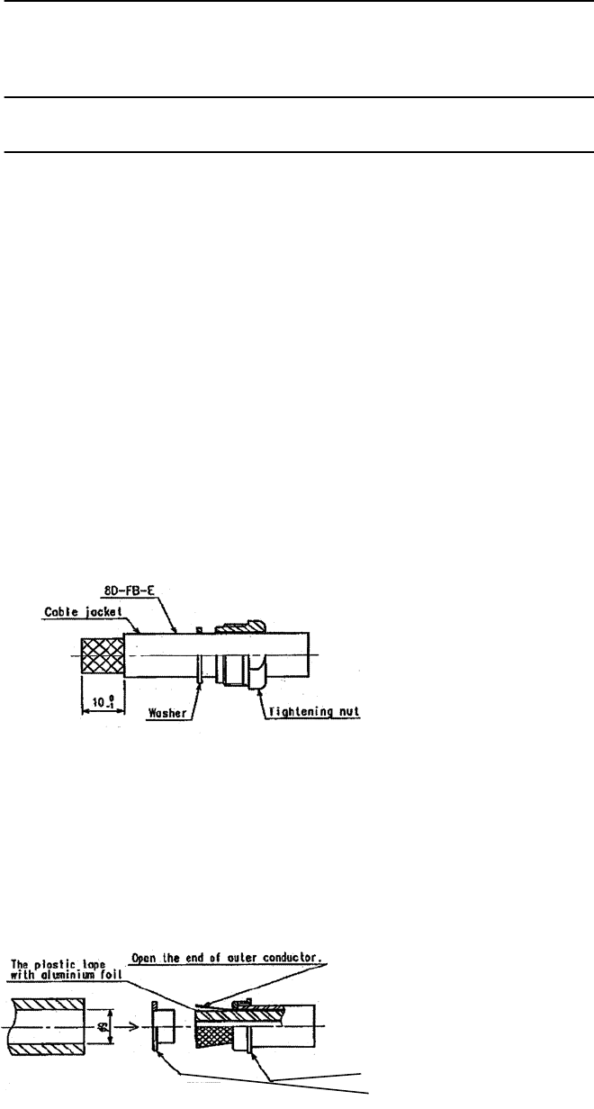
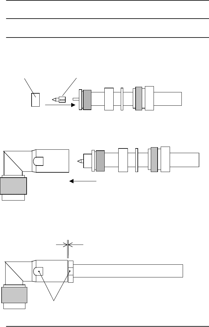
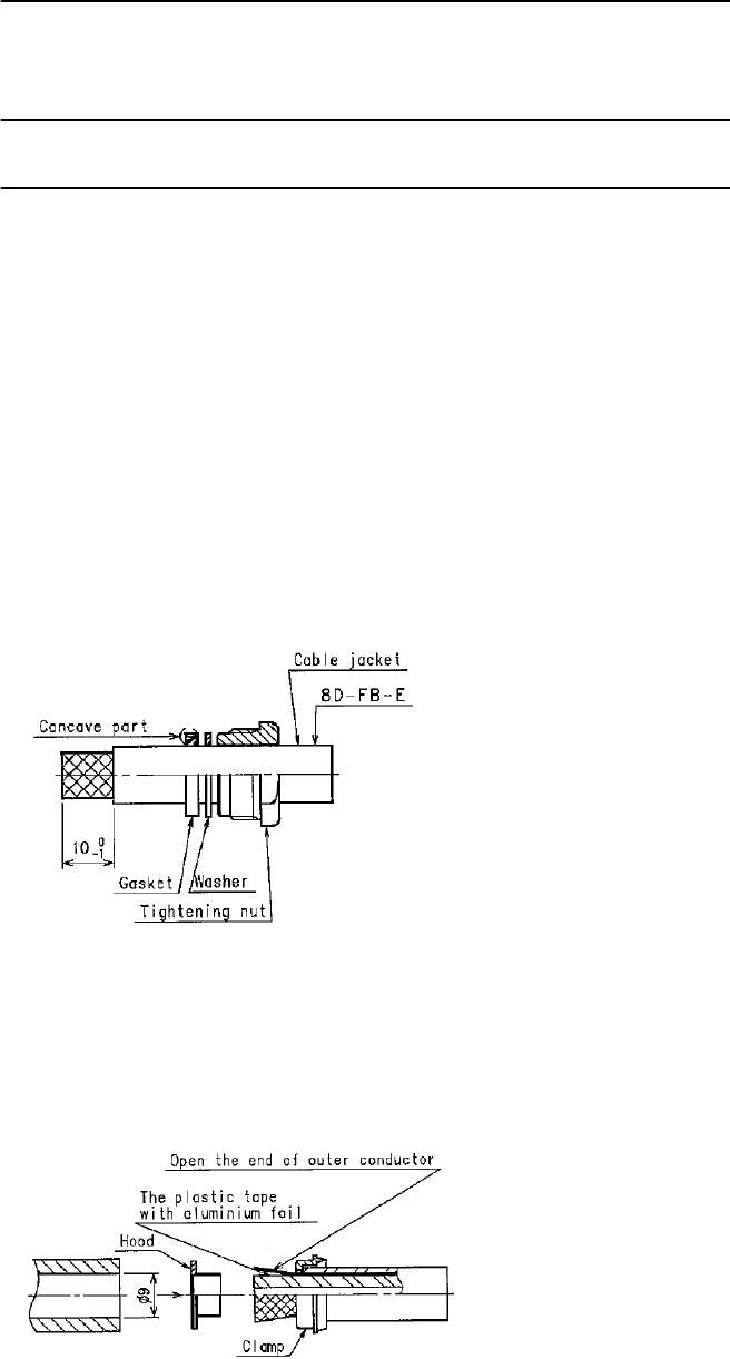
1 Pass the tightening nut, the washer and the gasket on the cable in
the order shown in the figure.
Then, strip the cable jacket in the diameter shown in the figure.
[Applicable cable: 8D-FB-E]
Notes: 1. Be careful of insertion direction for the gasket and the
tightening nut.
2. Be careful not to damage the outer conductor.
3. Do not reuse the gasket because the clamp deforms it after
tightening.
2 Insert the clamp to clamp the stripped cable jacket end. Open the
end of the outer conductor a little,
3 Insert the hood between the plastic tape with aluminium foil and
the outer conductor,
Note: Use the insertion stick to open the hole of about
φ
9. No gap is
allowed in between the clamp, the outer conductor and the hood.
CLAMP
HOOD
INSTALLATION ROI-S07045
2-102
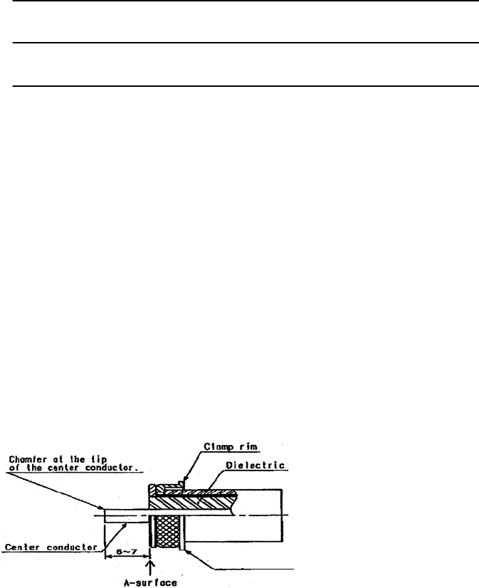
Chart 2-20 (Cont’d)
Step Procedure
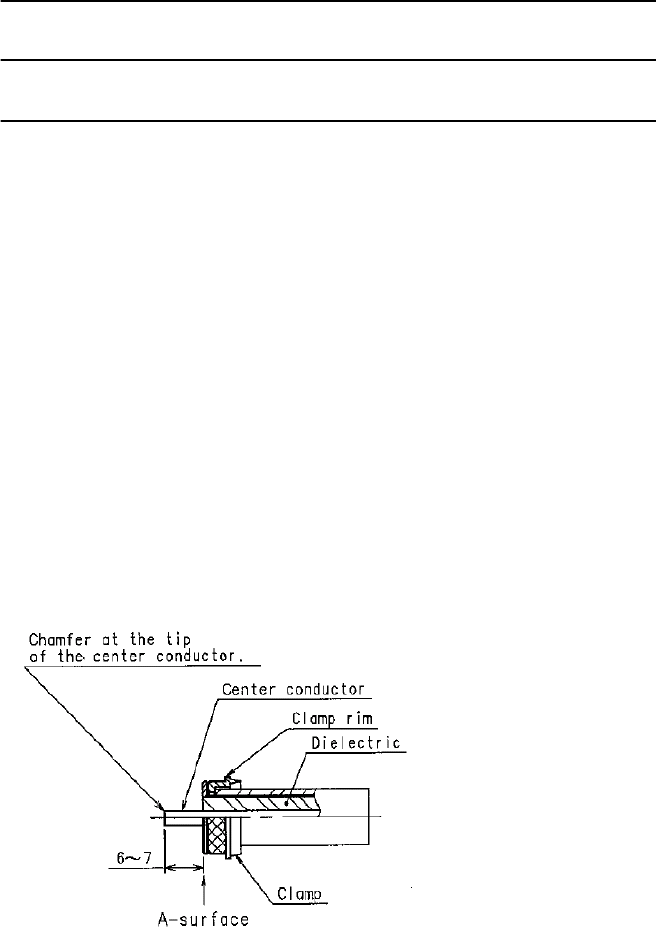
4 After inserting the hood, cut off the plastic tape with aluminium
foil and the dielectric at A-surface,
5 Cut off the part of the outer conductor exceeding the clamp rim
with a knife,
6 Check that distance between the tip of the center conductor and
A-surface is 6 to 7 mm,
If it is more than 7 mm, cut the center conductor to correct
length,
Notes: 1. Be careful not to damage the center conductor,
2. Chamfer at the tip of the center conductor,
3. There shall be no evidence of deviation or deformation or
burr at the tip of the center conductor.
CLAMP
ROI-S07045 INSTALLATION
2-103
Chart 2-20 (Cont’d)
Step Procedure
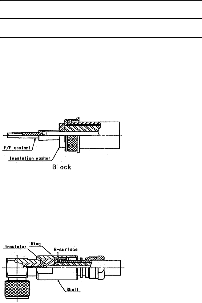
7 Insert the insulation washer over the center conductor, and
engage it with the F/F contact,
Notes: 1. No gap is allowed in between the F/F contact, the insulation
washer, and the dielectric.
2. The assembly unit after the completion of this process is
called “block”.
8 Combine the convex part of the clamp to the concave part of the
gasket, Then insert this block to the shell,
Note: Insert the hood until it hits the B-surface.
INSTALLATION ROI-S07045
2-104
Chart 2-20 (Cont’d)
Step Procedure
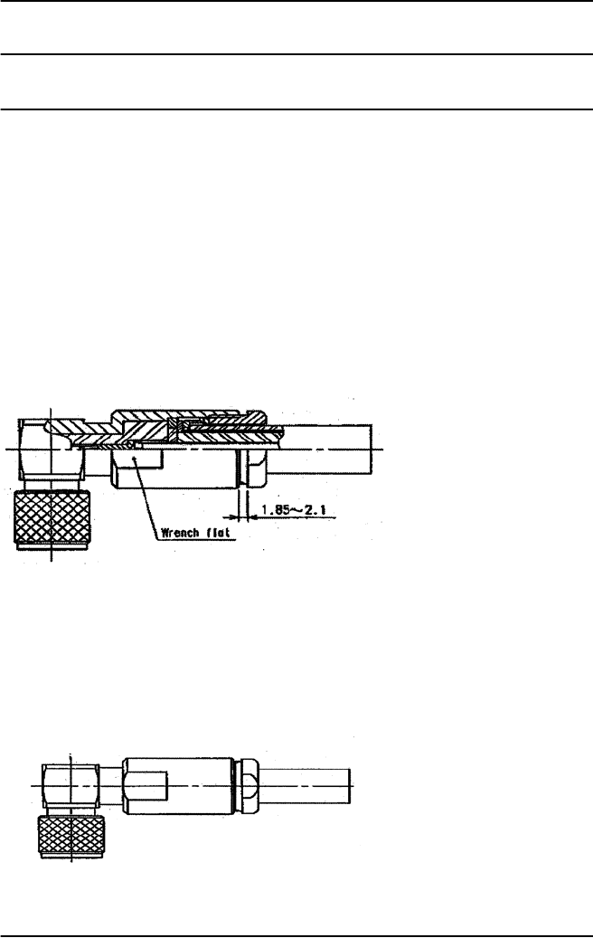
9 Tighten the tightening nut sufficiently until the gasket is cut by
the clamp and the tip of the clamp hits the washer,
Notes: 1. Torque for the tightening nut shall be 8 to 30 N•m.
2. When tightening the nut, tighten with wrench at the wrench
at the wrench flat.
3. Distance between the tightening nut and the LP shell is 1.85
to 2.1 mm for reference.
Tighten the nut sufficiently.
L-type dimension and cutting length of the cable.
Specified length L: Cutting length L−25.
ROI-S07045 INSTALLATION
2-105
Chart 2-21 Terminating Coaxial (IF Signal) with N-P
Connector (L Angle Type) used for TRP IF
IN/OUT (KOMINE made)
Step Procedure
Note: It is recommended that TNC (Male) L-angle connector for the
8D-FB IF cable is used to connect it to the MDP. When the N
(Male) straight connector is attached to the 5D-FB or 10D-FB
IF cable, use of the TNC (Male) - N (Female) (NJ-TNCP-LA)
L-angle adapter is needed.
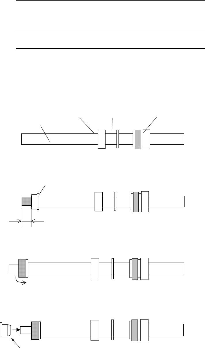
1 First fit the tying metal, washer and gasket on the cable.
2 Strip back the cable sheath, taking care not to damage the
braided shield, and fit the clamp.
3 Fold back the braided shield (separating the strands of the braid)
and trim it.
Note: Pay attention not to damage the plait.
4 Insert the ferrule.
GASKET WASHER TYING METAL
CABLE
CLAMP
9 mm
FERRULE
INSTALLATION ROI-S07045
2-106
Chart 2-21 (Cont’d)
Step Procedure
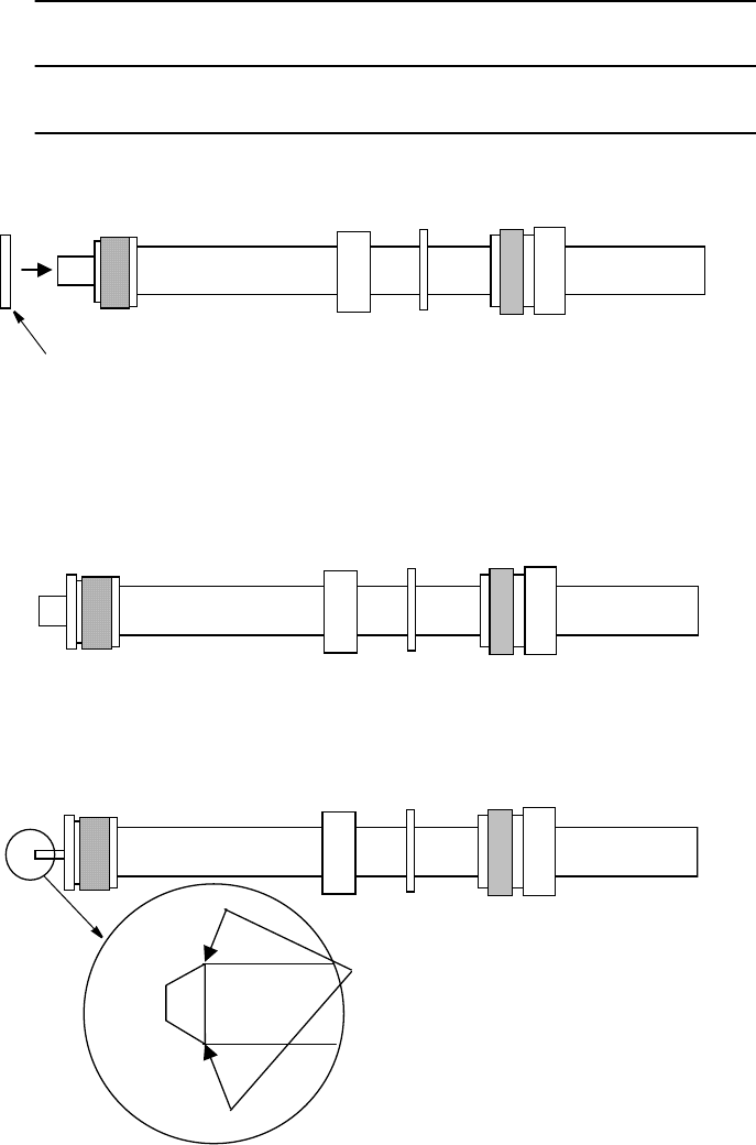
5 Fit the bushing.
6 Cut the aluminium foil and inner insulator away along the
bushing and retain the inner conductor.
7 Taper the edge of the center conductor using a file as shown in
the enlarged view below.
BUSH
Note: Pay attention not to let
protrusions and indents to occur.
ROI-S07045 INSTALLATION
2-107
Chart 2-21 (Cont’d)
Step Procedure
8 Mount the contact onto the center conductor and mount the
insulator onto the contact.
9 Insert the cable into the shell.
10 Tighten the tying metal by wrench using the wrench points.
(Tighten with torque of 4 to 10 N·m)
INSULATOR CONTACT
WRENCH POINT
LESS THAN 0.1 mm
(USUALLY NO GAPS)
INSTALLATION ROI-S07045
2-108
Chart 2-22 Terminating IF Coaxial Cable with N-P
Connector (L Angle Type) used for the TRP
IF IN/OUT (HIROSE made)
Step Procedure
Note: It is recommended that TNC (Male) L-angle connector for the
8D-FB IF cable is used to connect it to the MDP. When the N
(Male) straight connector is attached to the 5D-FB or 10D-FB
IF cable, use of the TNC (Male) - N (Female) (NJ-TNCP-LA)
L-angle adapter is needed.
1 Pass the tightening nut, the washer and the gasket on the cable in
the order shown in the figure.
Then, strip the cable jacket in the diameter shown in the figure.
[Applicable cable: 8D-FB-E]
Notes: 1. Be careful of insertion direction for the gasket and the
tightening nut.
2. Be careful not to damage the outer conductor.
3. Do not reuse the gasket because the clamp deforms it after
tightening.
2 Insert the clamp to clamp the stripped cable jacket end. Open the
end of the outer conductor a little,
3 Insert the hood between the plastic tape with aluminium foil and
the outer conductor,
Note: Use the insertion stick to open the hole of about
φ
9. No gap is
allowed in between the clamp, the outer conductor and the hood.
ROI-S07045 INSTALLATION
2-109
Chart 2-22 (Cont’d)
Step Procedure
4 After inserting the hood, cut off the plastic tape with aluminium
foil and the dielectric at A-surface,
5 Cut off the part of the outer conductor exceeding the clamp rim
with a knife,
6 Check that distance between the tip of the center conductor and
A-surface is 6 to 7 mm,
If it is more than 7 mm, cut the center conductor to correct
length,
Notes: 1. Be careful not to damage the center conductor,
2. Chamfer at the tip of the center conductor,
3. There shall be no evidence of deviation or deformation or
burr at the tip of the center conductor.
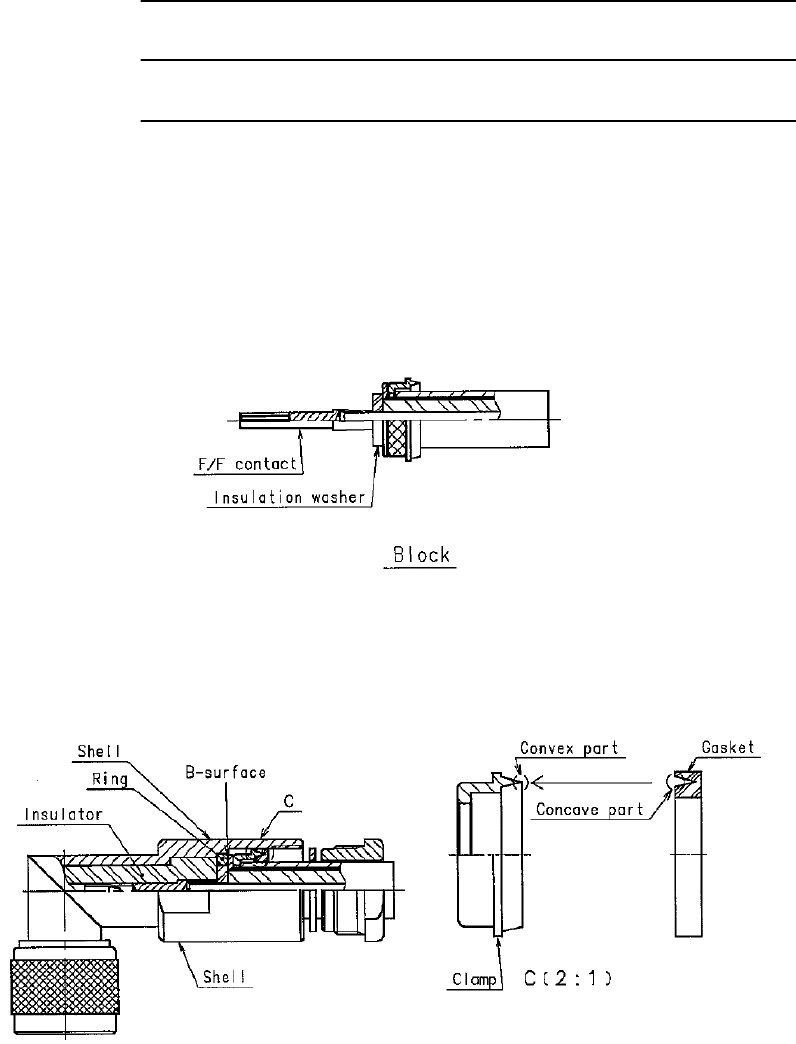
INSTALLATION ROI-S07045
2-110
Chart 2-22 (Cont’d)
Step Procedure
7 Insert the insulation washer over the center conductor, and
engage it with the F/F contact,
Notes: 1. No gap is allowed in between the F/F contact, the insulation
washer, and the dielectric.
2. The assembly unit after the completion of this process is
called “block”.
8 Combine the convex part of the clamp to the concave part of the
gasket, Then insert this block to the shell,
Note: Insert the hood until it hits the B-surface.
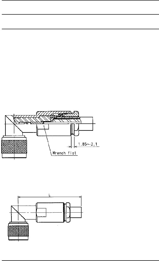
ROI-S07045 INSTALLATION
2-111
Chart 2-22 (Cont’d)
Step Procedure
9 Tighten the tightening nut sufficiently until the gasket is cut by
the clamp and the tip of the clamp hits the washer,
Notes: 1. Torque for the tightening nut shall be 8 to 30 N•m.
2. When tightening the nut, tighten with wrench at the wrench
at the wrench flat.
3. Distance between the tightening nut and the LP shell is 1.85
to 2.1 mm for reference.
Tighten the nut sufficiently.
L-type dimension and cutting length of the cable.
Specified length L: Cutting length L−25.
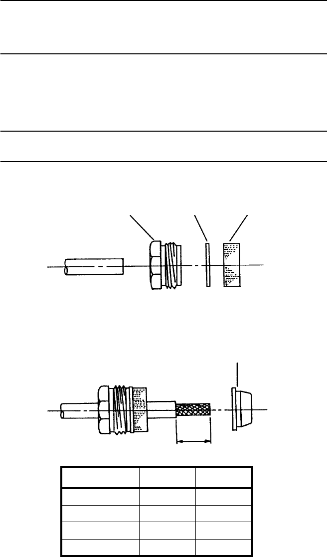
INSTALLATION ROI-S07045
2-112
Chart 2-23 Terminating IF Coaxial Cable
with N-P Connector (Straight Type) used for
TRP IF IN/OUT (HIROSE made)
N-type connector is used for the TRP side.
Note: When the N (Male) straight connector is attached to the IF
coaxial cable for the MDP IF IN/OUT, use of the TNC (Male) - N
(Female) (NJ-TNCP-LA) L-angle adapter is needed.
Step Procedure
1 First fit the lock nut, washer and gasket on the cable as shown.
2 Strip back the cable sheath, taking care not to damage the
braided shield, and fit clamp A.
3 Fold back the braided shield (separating the strands of the braid)
and trim it.
CABLE
LOCK NUT WASHER GASKET
CLAMP A
X
CONNECTOR CABLE X
N260 5D-FB 25 mm
N227 8D-FB 25 mm
N228 10D-FB 27 mm
N229 12D-FB 27 mm
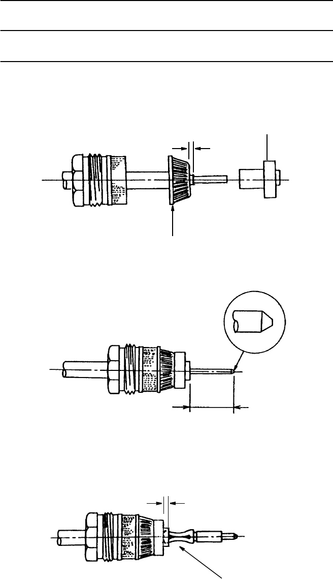
ROI-S07045 INSTALLATION
2-113
Chart 2-23 (Cont’d)
Step Procedure
4 Cut away the insulation from the center conductor and fit clamp
B. Be sure not to cut or scratch the conductor while stripping the
insulation.
5 Cut the center conductor. Taper the end of the center conductor
using a file as shown in the enlarged view below.
6 Mount the center contact onto the center conductor as shown.
Note: Insert the center contact into insulator (1.5 mm).
1.0 mm CLAMP B
CUT
12 mm
1.5 mm
CENTER CONTACT
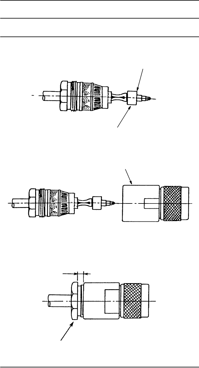
INSTALLATION ROI-S07045
2-114
Chart 2-23 (Cont’d)
Step Procedure
7 Mount the insulator onto the center contact.
8 Insert the cable into the connector shell.
9 Tighten the lock nut.
TAPERING SIDE
INSULATOR
CONNECTOR SHELL
LOCK NUT
Less than 0.5 mm
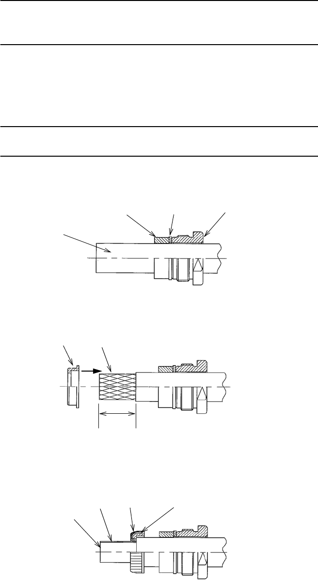
ROI-S07045 INSTALLATION
2-115
Chart 2-24 Terminating IF Coaxial Cable
with N-P Connector (Straight Type) used for
TRP IF IN/OUT (KOMINE made)
N-type connector is used for the TRP side.
Note: When the N (Male) straight connector is attached to the IF
coaxial cable for the MDP IF IN/OUT, use of the TNC (Male) - N
(Female) (NJ-TNCP-LA) L-angle adapter is needed.
Step Procedure
1 The clamp nut, the washer and the gasket are inserted in the
cable,
2 Strip the cable as below and disentangle the braid and insert the
clamp in the cable,
3 Turn the braid on the clamp inserted and cut the braid according
to the paragraph,
GASKET WASHER CLAMP NUT
CABLE
BRAID
CLAMP
25 mm
Do not scratch the braid wire.
BRAID
INSULATOR FOIL PARAGRAPH
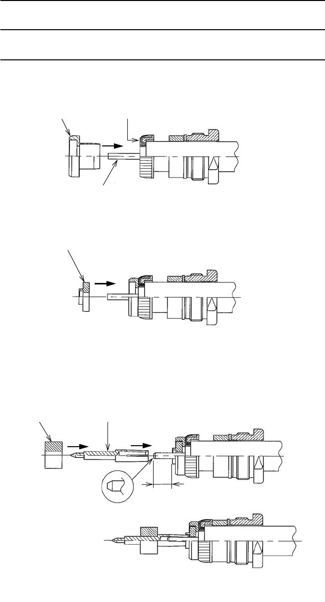
INSTALLATION ROI-S07045
2-116
Chart 2-24 (Cont’d)
Step Procedure
4 Cut the cable-insulator according to the surface that is turned the
braid and insert the ferrule,
5 Insert the insulator,
6 Cut the center-conductor as following size. Process the tip of
center-conductor like a taper with a file. (Do not have a curve
and burr.) Insert the center-contact in the center-conductor and
insert the insulator in the center-contact,
FERRULE
CENTER CONDUCTOR
The surface that is turned the braid.
Do not scratch the center conductor.
INSULATOR
12 mm
CENTER CONTACT
INSULATOR
Processing chart of the
tip of the center-conductor.
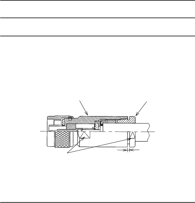
ROI-S07045 INSTALLATION
2-117
Chart 2-24 (Cont’d)
Step Procedure
7 Connector body is fit to the cable.
Fit in the cable end into the body and screw the clamp nut by
your hand first and tighten it with a torque wrench.
Confirm the space that it is less than 0. 5 mm between the body
and the cramp nut.
BODY CLAMP NUT
18/2 flats less than 0.5 mm
Tightening torque is more than 9.8 N•m (100 kgf•cm)
Note: Use torque wrench.
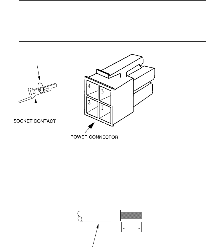
INSTALLATION ROI-S07045
2-118
Chart 2-25 Terminating Power Supply Cables with
Molex Connector
Step Procedure
1 Remove 3.0 to 3.5 mm of insulation.
CABLE
AWG#18-24
Note: Do not bend this part.
POWER SUPPLY CABLE
3.0 to 3.5 mm
FOR 48 V, 1A
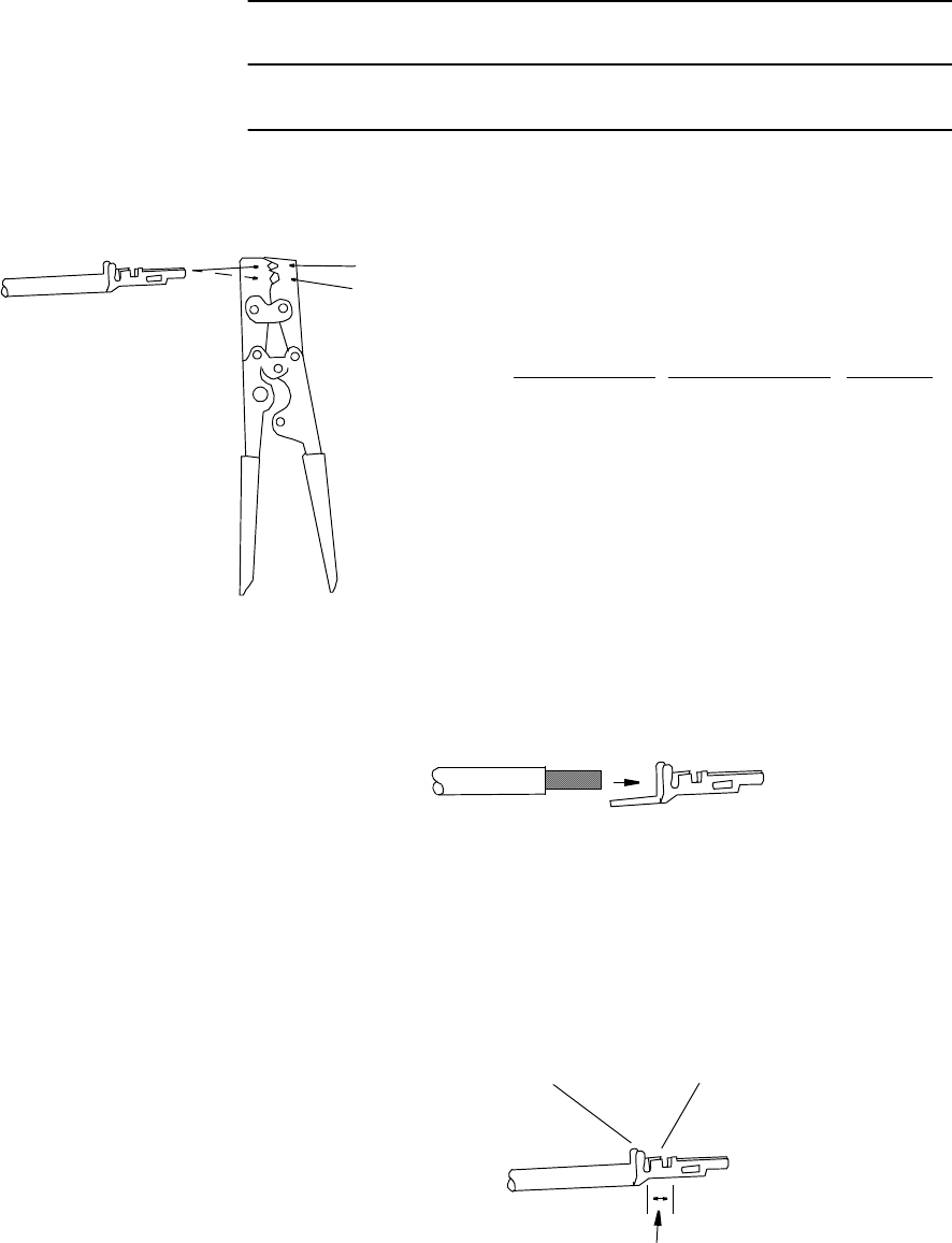
ROI-S07045 INSTALLATION
2-119
Chart 2-25 (Cont’d)
Step Procedure
2 Set the socket contact to position 1 or 2 of the hand crimping
tool.
3 Squeeze the handle of the hand crimping tool, insert cable into
socket contact.
4 The cable should fit, so insulation and bare wire are arranged as
shown.
5 Squeeze the handle of the hand crimping tool until the ratchet is
released.
HAND CRIMPING TOOL
57026-5000 Molex
or 57027-5000
( )
HAND CRIMPING
TOOL TYPE
57026-5000
57027-5000
OUTSIDE DIAMETER
OF CABLE
φ 1.5 to 1.8
φ 1.8 to 2.2
φ 2.3 to 2.6
φ 2.6 to 3.1
SET
POSITION
2
1
1
2
1
2
INSULATION BARREL WIRE BARREL
WIRE STRIP LENGTH
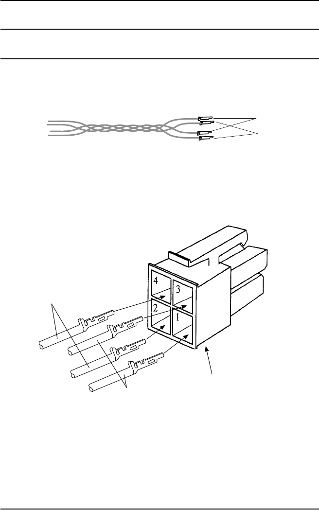
INSTALLATION ROI-S07045
2-120
Chart 2-25 (Cont’d)
Step Procedure
6 Twist cables for the power supply,
7 Insert the socket contacts into the power connector until they
lock.
Note: Twist power cables (+)/(−) to suppress inductive interference signals.
(+)
(−)
−48 V (*1)
GND (*2)
POWER CONNECTOR
Note: For H3040 DC-DC CONV,
(*1):
−
20 to
−
60 V (or 0 V)
(*2):0 V (or +20 to +60V)
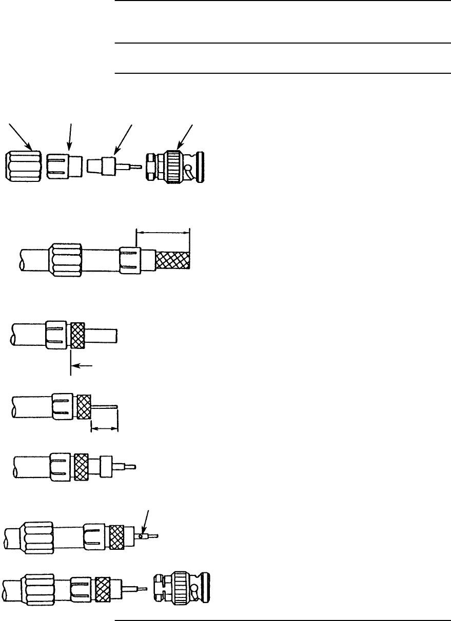
ROI-S07045 INSTALLATION
2-121
Chart 2-26 BNC Connector for 3C-2V Coaxial Cable
Assembling, Solder Type
Step Procedure
The following explains how to assemble BNC solder type as an example.
LOCK NUT CLAMP 1 CLAMP 2 SHELL
Step 1. Slide the lock nut onto the cable.
Strip the cable sheath, taking care
not to damage the braided shield
wires, and fit CLAMP 1.
(15.5 mm)*
(39/64”)*
Note *:Stripping measurements vary depend on the BNC
Step 2. Fold back the braided shield wire
around the CLAMP 1 (without
separating the strands of the
braid) and trim it.
trim
Step 3. Cut away the insulator from the
centre conductor and fit CLAMP
2. (Be sure not to cut or scratch
the conductor while stripping the
insulation.)
(7 mm)*
(9/32”)*
Note *:Stripping measurements vary depend on the BNC
Step 4. Solder the pin contact to center
conductor. Use a knife to remove
excess solder.
SOLDERING
Step 5. Insert the connectorized cable
into the BNC shell and fasten the
lock nut with a wrench.
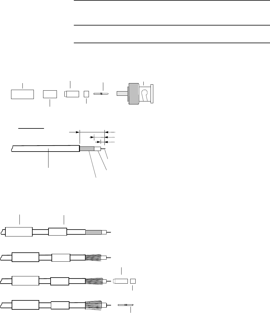
INSTALLATION ROI-S07045
2-122
Chart 2-27 BNC Connector for 3C-2V Coaxial Cable
Assembling, Crimping Type
Step Procedure
The following explains how to assemble BNC crimping type as an example.
Step 1. Strip coaxial cable as illustrated
left, (taking care not to damage
braided shield wire),
Step 2. Cut braided shield wire (without
unravel the strands of braid) and
trim it,
Step 3. Cut dielectric, (be sure not to cut
or scratch the centre conductor
while stripping the dielectric),
CENTER CONDUCTOR
DIELECTRIC
SHIELD WIRE
SHEATH
(15 mm)*
(6.3 mm)*
(4 mm)*
STRIPPING
Note*: Stripping measurements vary depending on the
BNC type.
ABC
contraction sleeve
ferrule
pin contact BNC shell
BNC plug
CONTRACTION SLEEVE FERRULE
Step 4. Slide contraction sleeve and
ferrule onto the cable,
Step 6. Slide pin contact until it bottoms
against the centre conductor,
insulator
Step 6. Slide braid tube and insulator
among braided shield wire and
dielectric,
braid tube
Step 5. Fan braided shield wire,
BRAID TUBE
INSULATOR
PIN CONTACT
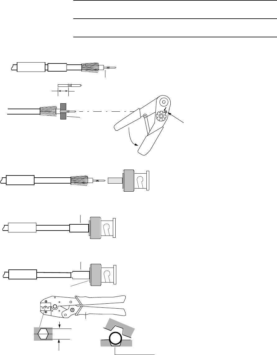
ROI-S07045 INSTALLATION
2-123
Chart 2-27 (Cont’d)
Step Procedure
Step 7. Crimp pin contact,
CRIMP
PIN CONTACT
CRIMPING TOOL
crimping area
CRIMP
Step 8. Slide carefully the cable into BNC
shell until insulator butts against
BNC body,
Step 9. Slide ferrule over shield wire until
it bounds against the BNC shell
body,
FERRULE
Step 10.Crimp ferrule as close as possible
to the BNC shell body and trim the
excess of braid,
CRIMPING TOOL
Crimp ferrule as close as possible.
TRIM
Use suitable crimping size
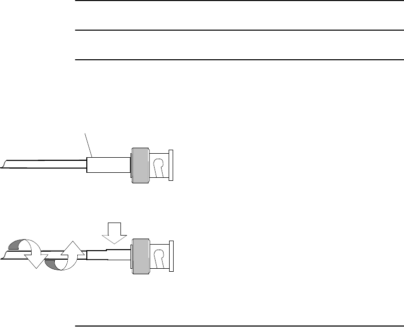
INSTALLATION ROI-S07045
2-124
Chart 2-27 (Cont’d)
Step Procedure
Step 11.Position contraction sleeve over
ferrule and BNC,
Step 12.Heat contraction sleeve until it
contracts.
CONTRACTION SLEEVE
HEATED AIR
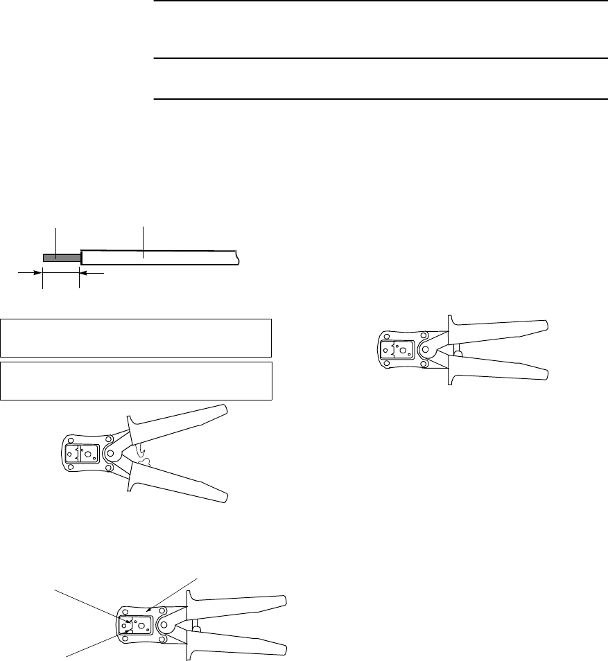
ROI-S07045 INSTALLATION
2-125
Chart 2-28 D-Sub High Density Crimp Contacts
Assembly
Step Procedure
The following explains how to assemble high density crimp contacts used
for HARTING hand crimp tool as an example.
Step 1. Strip the jacket for 2.5 −0/+0.5 mm
as shown left and check if stranded wire
is not damaged,
Step 2. Place the handles in the open
position as shown left,
STRANDED WIRE
2.5 −0/+0.5 mm
Step 3. Select the suitable chamber for
the selected wire,
Step 7. Take out the crimped contacts
from the chamber. Check if it
should not be scratched or
transformed.
Step 4. Insert contact in the selected
chamber,
Applicable wire size: 0.14 - 0.22 mm
2
(AWG26 - 24),
stranded, maximum insulation:
φ
1.38 mm
CRIMP TOOL
(09 88 999 0596)
Note: When the handles are in close position, squeeze handles completely until safety ratchet is
released.
JACKET
CHAMBER FOR 0.22 mm2 (AWG 24)
CHAMBER FOR 0.14 mm2 (AWG 26)
INDICATION OF THE PART NUMBER
Step 5. Insert the prepared wire in the
contact,
Step 6. Squeeze the handles together
completely until the safety ratchet
clicks to open,
Stamped male contacts: 09 56 000 8175 (Level S4),
High density male connectors: 09 56 300 5601 (#44)
Crimping/inserting contacts process
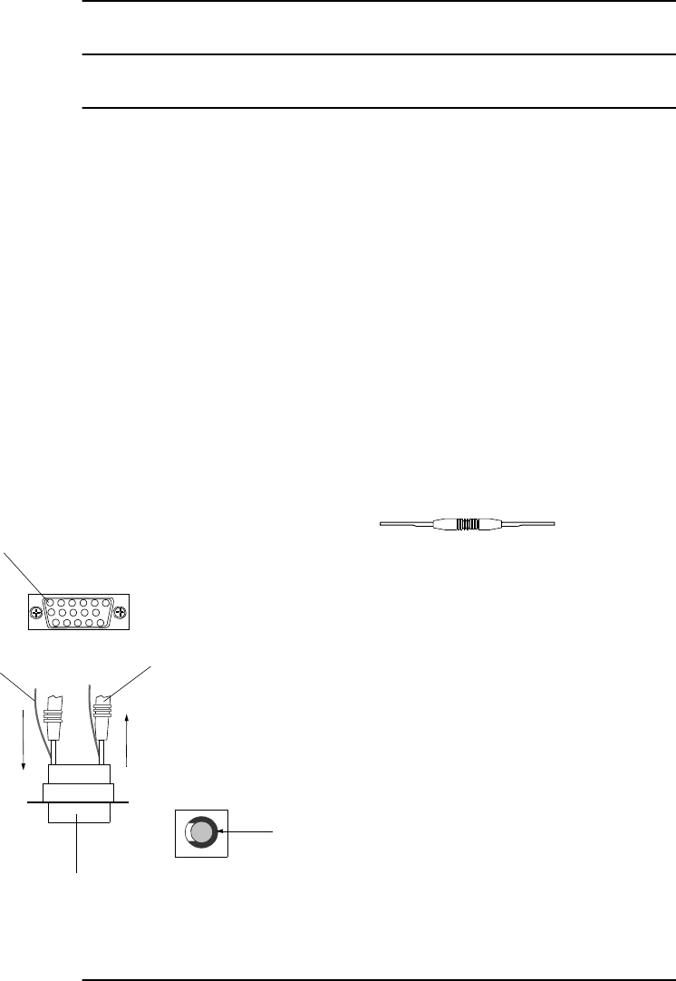
INSTALLATION ROI-S07045
2-126
Chart 2-28 (Cont’d)
Step Procedure
Step 8. After crimping the stranded wire to
the contact using a hand tool, insert
the contact into the contact chamber
with the tool, working from the
wiring side,
Step 9. You can here the contacts snap
home, audible “click”,
Removing crimp contacts
Step 1. Position the tool from the wiring
side as shown left and insert into the
contact chamber. The contact can
then easily be removed from the
wiring side together with itself and
reinserted in a different chamber.
Step 10.Check if they are securely in
place with giving the wire a
gentle pull.
INSERTION AND REMOVAL TOOL
(09 99 000 0513)
WIRE
CONNECTOR
INSERTION AND REMOVAL TOOL
[REMOVAL]
Contact can be removed
together with wire.
[INSERTION]
Contact can be inserted
together with wire.
CONTACT CHAMBER
Insertion and removal tool
Position the

ROI-S07045 INSTALLATION
2-127
2.8 Wiring and Forming
Chart 2-29 Wiring and Forming
Step Procedure
1 Connect cables for, signal interface, power supply, IF IN/OUT
and ground to the proper connector of the MDP.
(1) Connect ground cable to the ground terminal
(2) Connect IF cable to IF IN/OUT connector.
(3) Connect power supply cable to SELV connector.
(4) Connect STM-1, Aux. signal cables to proper connector.
(5) Connect XIF coaxial cables to opposite MDP. (XPIC
configuration only.)
(6) Connect XPIC CTRL cables to opposite MDP. (XPIC
configuration only.)
Note: When disconnect cables, perform it in revers steps.
2 Fix the cables using cable binder to the rack as like as indicated
position.
Notes: 1. Do not cross the cables on front of indicators and power
switch used for maintenance.
2. Take suitable bend radius to wiring the IF cable.
(5DFB: 45mm or more, 8DFB, 10DFB: 70mm or more)
3. For the IF cable connection, it is recommended to use
adapter. (Applicable adapters are listed table below).
Table 2-6 IF Cable Adapter
IF Cable Adapter
TNC(P) - N(J) TNC(P) - TNC(J)
5D-FB √
8D-FB √√
10D-FB √
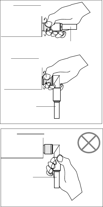
INSTALLATION ROI-S07045
2-128
Caution: Tighten the TNC-male connector of
IF cable to the MDP with engage
connector nut only using fingers and
holding the cable with another hand.
Tighten the engage connector nut
only for the L-angle connector also.
(Tightening Torque: 0.3 to 0.5 N•m
(3 to 5kg•cm))
MDP
MDP
IF CABLE
IF CABLE
MDP
IF CABLE
Straight Type
L-Angle Type
L Angle Type
Caution: If rotate other parts of the L-angle
connector as illustrated left, it can
cause connector damage.
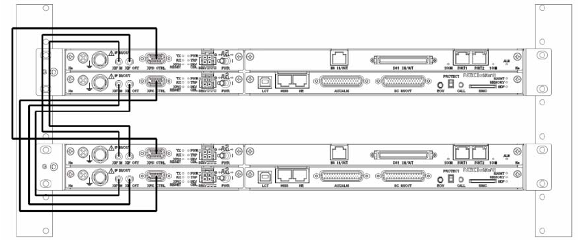
ROI-S07045 INSTALLATION
2-129
Fig. 2-8 Cable Wiring for the XPIC System
Notes: 1. Connect XIF cable to between XIF IN (Main Master) and XIF OUT (Sub
Master), and XIF OUT (Main Master) and XIF IN (Sub Master).
2. Connect XPIC CTRL cables to between XPIC CTRL (Main Master) and
XPIC CTRL (Sub Master).
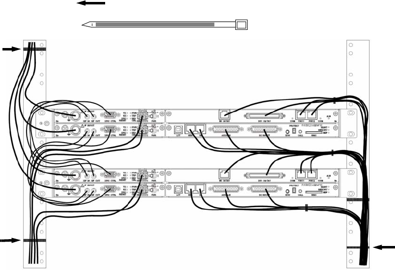
INSTALLATION ROI-S07045
2-130
Fig. 2-9 Cable Wiring and Forming
Fix the cables to the mounting rack with cable binder.
Cable Binder
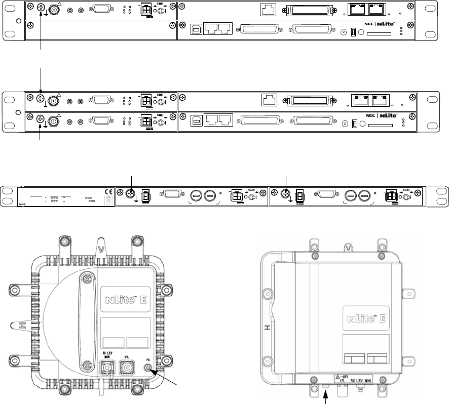
ROI-S07045 INSTALLATION
2-131
2.9 Frame Grounding
In mounting the MDP and TRP, perform frame grounding. The location of
the frame grounding in each MDP and TRP is shown in Fig. 2-10, and the
connection for frame grounding is shown in Fig. 2-11.
Note: Connect the Frame Ground (FG) terminal on the MDP to the
mounting rack with the earth cable. In addition, connect the
mounting rack to the indoor earth terminal with the earth cable
and connect the FG terminal on the TRP to the ground (refer to
Fig. 2-11).
Fig. 2-10 Location of Frame Ground
1+0 SYSTEM
FRAME GROUND TERMINAL
FG
1+1 SYSTEM
MDP
6-38 GHz TRP NHG/NHP Type
FRAME GROUND TERMINAL
SELV
PWR PULL
PWR
ALM FUSE (250V/8AH)
−
43V
G
OUT
STD
G
SELV
PWR PULL
PWR
ALM FUSE (250V/8AH)
−
43V
G
OUT
STD
G
NWA-011060-001 DC-DC CONV UNIT
SER No. DATE ,
WEIGHT 2.5kg
MADE IN JAPAN
NEC Corporation
TOKYO JAPAN
1+0 System STD Input : 20 60V 3.4A 1.0A
Output :
−
43V 1.3A
1+1 System STD Input : 20 60V 1.3A
×
2
3.4A 1.0A
×
2 Output :
−
43V
FRAME GROUND TERMINAL FRAME GROUND TERMINAL
DC-DC CONV (Optional)
18-38 GHz TRP NHG2 Type
FG
SELV
!
AUX/ALM
LCT NMS NE SC IN/OUT EOW
PROTECT
CALL MMC
MAINT
MEMORY
MDP
XIF IN XIF OUT
IF IN/OUT TX
RX
RESET
XPIC CTRL XPIC
PWR
TRP
MD/
CBL PWR
PULL
G
G
ALM
100M PORT 1 PORT 2 100M Ns
Ns DS1 IN/OUT
WS IN/OUT
N
SELV
!
AUX/ALM
LCT NMS NE SC IN/OUT EOW
PROTECT
CALL MMC
MAINT
MEMORY
MDP
XIF IN XIF OUT
IF IN/OUT TX
RX
RESET
XPIC CTRL XPIC
PWR
TRP
MD/
CBL PWR
PULL
G
SELV
!
XIF IN XIF OUT
IF IN/OUT TX
RX
RESET
XPIC CTRL XPIC
PWR
TRP
MD/
CBL PWR
PULL
G
G
ALM
100M PORT 1 PORT 2 100M
Ns
Ns
WS IN/OUT Ns
N
DS1 IN/OUT
(Blank)
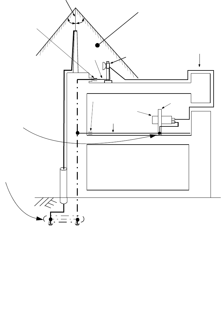
INSTALLATION ROI-S07045
2-132
Fig. 2-11 Connection for Frame Grounding (1/2)
EARTH LINE
INDOOR EARTH GROUND TERMINAL
MDP
TRP COAXIAL CABLE
PROTECT AREA
LIGHTNING ROD
OUTDOOR EARTH GROUND TERMINAL
(EXISTING OR CUSTOMER SUPPLIED)
EARTH LINE
GROUND
LEVEL
Cautions: 1. Install the TRP within the area protected by lightning rod.
2. To avoid surge currents caused by lightning circulating in the
equipment earth system, connect the equipment earth system
(frame ground) to ground of the lightning rod at ground level.
Note:Frame Ground terminal of the MDP (5 mm square cable (means more
than 2.5 mm diameter cable (AWG #10) is recommended to apply for the
earth grounding. The proper press fix terminal tool shall be used.)
This connection is an example.
RACK
30°30°
(Grounding Resistance:
less than 10 ohms)
This is the buried earth wire.
This type of wire is not an insulated
winding wire and recommends to
make a naked wire.
Use a copper grounding conductor to
ground the rack.
The grounding conductor to the CO
GND be connected to the rack.
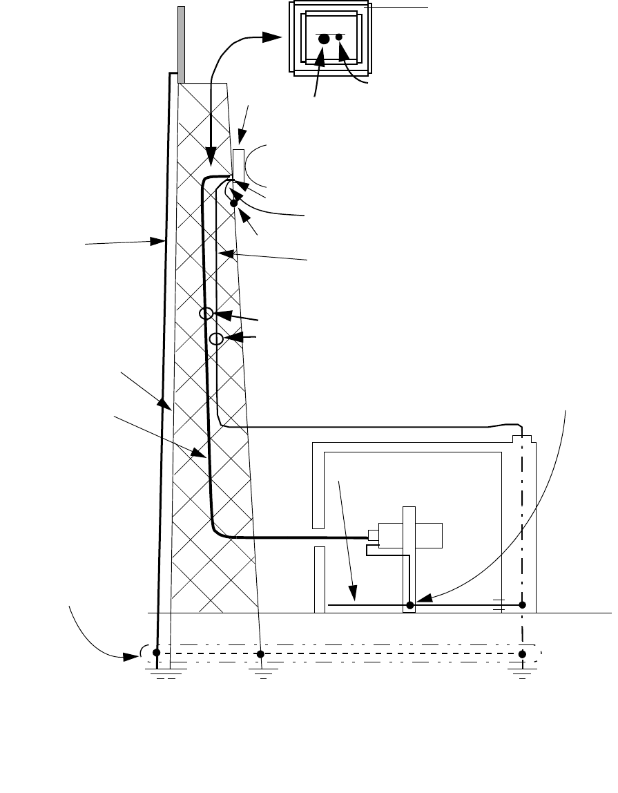
ROI-S07045 INSTALLATION
2-133
Fig. 2-11 Connection for Frame Grounding (2/2)
LIGHTNING ROD
EARTH LINE
TRP
FG
EARTH LINE*
COAXIAL CABLE
INDOOR EARTH
GROUND
LEVEL
MDP
(Grounding-resistance:
less than 10 ohms)
Notes:* NEC recommends that frame ground of TRP should be connected to earth line as NEC’s
standard installation.
EP: Earth Ground Point of tower
FG: Frame Ground terminal of the MDP (5 mm square cable (means more than 2.5 mm
diameter cable (AWG #10) is recommended to apply for the earth grounding. The proper
press fix terminal tool shall be used.)
This connection is an example.
ISOLATED FROM
TOWER
(Grounding-resistance:
less than 10 ohms)
(Grounding-resistance
of tower: less than
Grounding cable for TRP should be
connected to the nearest EP of the tower.
EP
LINE
It lets through the center of the steel
tower as much as possible.
The coaxial cable lets through the inside of the steel tower.
The earth between TRP-MDP lets through the inside of the
steel tower.
COAXIAL CABLE
EARTH LINE
This is the buried earth wire.
This type of wire is not an in-
sulated winding wire and
recommends to make a na-
ked wire.
10 ohms)
Use a copper grounding conductor to ground the rack.
The grounding conductor to the CO GND be connected to the rack.
TOWER
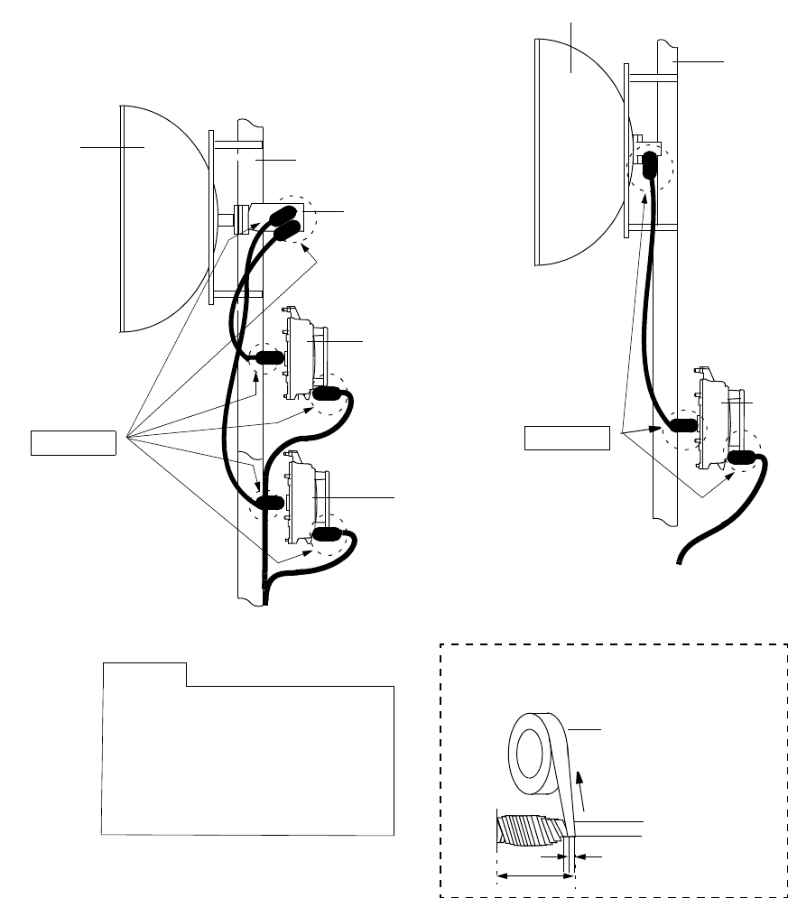
INSTALLATION ROI-S07045
2-134
2.10 Waterproof Protection
After cable connection, the following parts should be wrapped by self-
bonding tape for waterproof (see Fig. 2-10).
Fig. 2-12 Location of Connector for Waterproof (1/2)
POLE
ANT
6 GHz BAND TRP
POLE
ANT
HYB/COUPLER
TRP
TRP
These parts should be wrapped
the self-bonding tape tightly, twice
or more around the IF cable
connector and IF IN/OUT
connector of the TRP for
waterproof.
Note A
Note A
Note A
TRP
Caution: Before connecting the IF cable between the MDP
and TRP, using the circuit tester, check that the
resistance of the I/F cable between center
conductor and insulation is more than 100 M
Ω.
SELF-BONDING
TAPE
STRETCH
Wrap twice the IF IN/OUT connector with
self-bonding tape for waterproofing.
A HALF OF TAPE WIDTH
TRP
TWICE
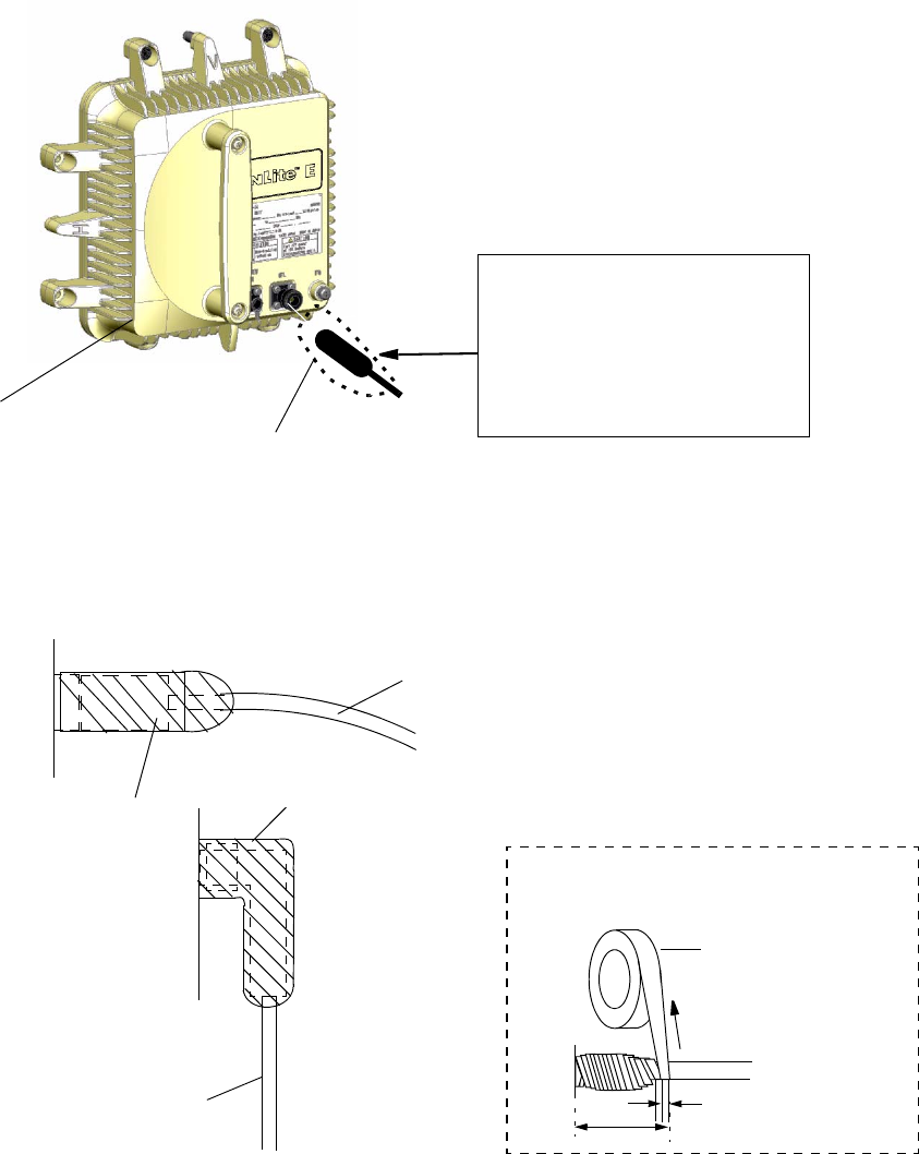
ROI-S07045 INSTALLATION
2-135
Fig. 2-12 Location of Connector for Waterproof (2/2)
TRP
IF CABLE
SELF-BONDING TAPE
TRP
IFL CONNECTOR
Note: The self-bonding tape should be prepared by customer.
SELF-BONDING TAPE
TRP
IF CABLE IN CASE OF L−ANGLE
6-38 GHz BAND TRP
This part should be wrapped the
self-bonding tape tightly, twice or
more around the IF cable
connector and IF IN/OUT
connector of the TRP for
waterproof.
Caution: Before connecting the IF cable between the
MDP and TRP, using the circuit tester,
check that the resistance of the I/F cable
between center conductor and insulation is
more than 100 M
Ω.
SELF-BONDING
TAPE
STRETCH
Wrap twice the IF IN/OUT connector with
self-bonding tape for waterproofing.
A HALF OF TAPE WIDTH
TRP
TWICE
For NHG Type TRP
INSTALLATION ROI-S07045
2-136
136 pages
(This page is intentionally left blank.)

ROI-S07045 INITIAL LINE UP
3-1
3. INITIAL LINE UP
This section explains instructions for the initial lineup of the equipment.
Included is information on start-up, shut-down, MDP and TRP equipment
setting, antenna orientation and lineup test between two stations.
When the PASOLINK Monitor is used for RX LEV monitoring, connect
the X0818 PASOLINK Monitor to the TRP. The PASOLINK Monitor
operates on a dry battery (6F22/9 V).
Notes: 1. Insert the battery with correct polarity.
2. When the PASOLINK Monitor will not be used for extended
periods of time, remove the battery to avoid damage from
battery leakage and corrosion.
3. When the PASOLINK Monitor will be connected to the TRP,
control corresponding TRP to Antenna Alignment mode
using LCT in Maintenance ON.
INITIAL LINE UP ROI-S07045
3-2
3.1 Start-up
The procedure for starting the equipment is shown in Chart 3-1.
Warnings: 1. The –48 V DC is superimposed on the centre conductor
of the IF coaxial cable between the MODEM and the
TRP. Connecting test equipment directly to this terminal
may damage it and touching the coaxial cable core may
cause electrical shock.
2. Do not disconnect the IF cable between the MODEM and the
TRP in operating condition, to avoid damaging the NLite N,
turn the MDP power OFF before connecting/disconnecting
the IF cable.
3. Do not allow open or short circuit of TRP TX output with
the TX power on conditions. Perform the TX Mute
control in the Maintenance mode or turn the PWR switch
off at the MDP before disconnecting cable or feeder from
the TRP TX output.
4. After turning ON the equipment, wait at least 1 minute before
turning it OFF again. Repeatedly turning the power ON and
OFF within a short interval may cause the NLite N to fail.
Cautions:1. Be careful top surface above MODEM of the MDP and
the TRP are hot in operation.
2. When replacing the MODEM, 2P LAN INTFC or DC-DC
CONV (optional) turn off the PWR switch and disconnect all
cables connected to the module which is to be replaced.
3. When dismounting the ( ) INTFC, turn off the PWR switch on
the MODEM and disconnect all cables connected to the ( )
INTFC.

ROI-S07045 INITIAL LINE UP
3-3
Chart 3-1 Start-up
Cautions: 1. Do not apply a voltage to the equipment that varies
sharply. The equipment may operate improperly.
2. Do not remove/connect the IF cable with the MDP
power ON. Turn the MDP power OFF before
connecting/disconnecting the IF cable, or equipment
may be damaged.
Apparatus:
Suitable Screwdriver
Digital Multimeter
Step Procedure
Notes: 1. The TRP power is supplied from the MDP
2. Refer to the DC Power Connection-2 for Start-up
procedure when the NLite N+ TRP is connected to the
NLite N TRP.
DC Power Connection-1
1+0 SYSTEM
1 Check that the IF cable between the MODEM and the TRP is
firmly connected,
2 Before connecting the power cable connector to the MODEM,
check that the SELV input voltage is −48V (allowable range;
within –40.5 to –57 V) with the digital multimeter, (see Fig. 3-1),
3 Pull out the PWR switch lever and turn on,
4 Confirm that the PWR indicator on the MODEM is ON.
1+1 SYSTEM
1 Check that the IF cable between the No.1 MODEM and the No.
1 TRP is connected,
2 Before connecting the power cable connector to the No.1
MODEM, check that the SELV input voltage is −48V
(allowable range, within –40.5 to –57 V) with the digital
multimeter, (see Fig. 3-1),
3 Pull out the PWR switch lever and turn on, (see Fig. 3-1),
4 Confirm that the PWR indicator on the No.1 MODEM is ON.
5 Repeat steps 1 to 3 for No.2 MODEM,
6 Confirm that PWR indicator on the No.2 MODEM is ON.
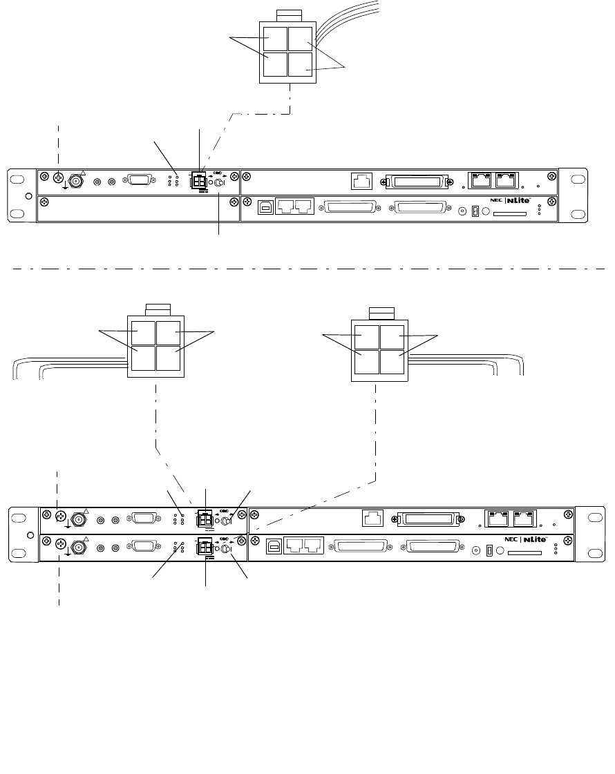
INITIAL LINE UP ROI-S07045
3-4
Fig. 3-1 DC Power cable Connection and Power ON/OFF (1/2)
PWR SWITCH
SELV
1+1 CONFIGURATION
MDP
PWR SWITCH
PWR LED
1+0 CONFIGURATION
MDP
PWR LED
SELV
PWR SWITCH
PWR LED SELV
MODEM
No.1 MODEM
No.2 MODEM
Caution: The NLite N operates only negative voltage (–48 V). Therefore, the power supply
system for the existing equipment which is used floating power supply (–20 to –60 V/
+20 to +60 V) must not be connected to the NLite N.
When the MDP NLite N is used with another type TRP (e.g. NLite L TRP), optional
DC-DC CONV module must be installed to the MDP NLite N. The TRP will be
shorten it’s life or may be damaged if not used optional DC-DC CONV module.
4
21
3
GND
–48 V
POWER SUPPLY
No.1 POWER SUPPLY
3
1
2
4GND
–48 V
No.2 POWER SUPPLY
3
1
2
4GND
–48 V
SELV
!
AUX/ALM
LCT NMS NE SC IN/OUT EOW
PROTECT
CALL MMC
MAINT
MEMORY
MDP
XIF IN XIF OUT
IF IN/OUT TX
RX
RESET
XPIC CTRL XPIC
PWR
TRP
MD/
CBL PWR
PULL
G
G
ALM
100M PORT 1 PORT 2 100M Ns
Ns DS1 IN/OUT
WS IN/OUT
N
SELV
!
AUX/ALM
LCT NMS NE SC IN/OUT EOW
PROTECT
CALL MMC
MAINT
MEMORY
MDP
XIF IN XIF OUT
IF IN/OUT TX
RX
RESET
XPIC CTRL XPIC
PWR
TRP
MD/
CBL PWR
PULL
G
SELV
!
XIF IN XIF OUT
IF IN/OUT TX
RX
RESET
XPIC CTRL XPIC
PWR
TRP
MD/
CBL PWR
PULL
G
G
ALM
100M PORT 1 PORT 2 100M
Ns
Ns
WS IN/OUT Ns
N
DS1 IN/OUT
(Blank)

ROI-S07045 INITIAL LINE UP
3-5
Chart 3-1 (Cont’d)
Step Procedure
Notes: 1 The TRP power is supplied from the MDP.
2 Refer to the DC Power Connection-1 for Start-up
procedure when the NLite N TRP is connected to the
NLite N TRP.
DC Power Connection-2 (DC-DC CONV)
1+0 SYSTEM
1 Check that the IF cable between the MODEM and the TRP is
connected,
2 Connect the power cable to –43 V/OUT of the DC-DC CONV
and SELV of the MODEM as shown in Fig. 3-1 (2/2),
3 Before connecting the power cable connector to the SELV
of the DC-DC CONV, check that the rated input voltage
is −24V/−48V (allowable range; within –20 to –60 V) or
+24V/+48V (allowable range; within +20 to +60 V) with
the digital multimeter, (see Fig. 3-1),
4 Pull out the PWR switch lever of the DC-DC CONV and turn
on,
5 Confirm that the PWR indicator on the DC-DC CONV is ON,
6 Pull out the PWR switch lever of the MODEM and turn on,
7 Confirm that the PWR indicator on the MODEM is ON.
1+1 SYSTEM
1 Check that the IF cable between the No.1 MODEM and the No.
1 TRP, is connected,
2 Connect the power cable to –43 V/OUT of the No.1 DC-DC
CONV and SELV of the No.1 MODEM as shown in Fig. 3-1 (2/
2),
3 Before connecting the power cable connector to the SELV
of the DC-DC CONV, check that the rated input voltage
is −24V/−48V (allowable range; within –20 to –60 V) or
+24V/+48V (allowable range; within +20 to +60 V) with
the digital multimeter, (see Fig. 3-1),
4 Pull out the PWR switch lever of the No.1 DC-DC CONV and
turn on,
5 Confirm that the PWR indicator on the No.1 DC-DC CONV is
ON,

INITIAL LINE UP ROI-S07045
3-6
Chart 3-1 (Cont’d)
Step Procedure
6 Pull out the PWR switch lever of the No.1 MODEM and turn
on,
7 Confirm that the PWR indicator on the No.1 MODEM is ON,
8 Repeat steps 1 to 7 for No.2 MODEM,
9 Confirm that PWR indicator on the No.2 MODEM is ON.
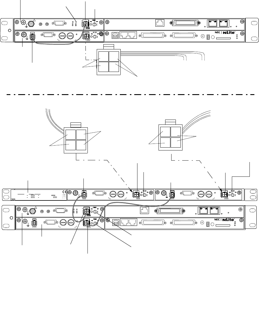
ROI-S07045 INITIAL LINE UP
3-7
Fig. 3-1 DC Power cable Connection and Power ON/OFF (2/2)
N
SELV
PWR PULL
PWR
ALM FUSE (250V/8AH)
−
43V
G
OUT
STD
+
SELV
PWR PULL
PWR
ALM FUSE (250V/8AH)
−
43V
G
OUT
STD
+
NWA-011060-001 DC-DC CONV UNIT
SER No. DATE ,
WEIGHT 2.5kg
MADE IN JAPAN
NEC Corporation
TOKYO JAPAN
1+0 System STD Input : 20 60V 3.4A 1.0A
Output :
−
43V 1.3A
1+1 System STD Input : 20 60V 1.3A
×
2
3.4A 1.0A
×
2 Output :
−
43V
SELV
!
AUX/ALM
LCT NMS NE SC IN/OUT EOW
PROTECT
CALL MMC
MAINT
MEMORY
MDP
XIF IN XIF OUT
IF IN/OUT TX
RX
RESET
XPIC CTRL XPIC
PWR
TRP
MD/
CBL PWR
PULL
SELV
ALM
PWR
PWR
PULL
+
G
G
100M PORT 3 PORT4 100M
ALM
Ns
DS1 IN/OUT
WS IN/OUT
STD
FUSE (250V/8AH)
−
43V
G
OUT
Ns
SELV
!
AUX/ALM
LCT NMS NE SC IN/OUT EOW
PROTECT
CALL MMC
MAINT
MEMORY
MDP
XIF IN XIF OUT
IF IN/OUT TX
RX
RESET
XPIC CTRL XPIC
PWR
TRP
MD/
CBL PWR
PULL
G
SELV
PWR PULL
PWR
ALM FUSE (250V/8AH)
−
43V
G
OUT
STD
+
G
Ns
DS1 IN/OUT
WS IN/OUT
100M PORT 3 PORT4 100M
ALM
Ns
N
PWR SWITCH (MDP)
SELV
MDP
0 V/(or +20 to +60V)
–20 to –60V/(or 0V)
1+0 CONFIGURATION
POWER SUPPLY
PWR LED
MODEM
No.1 POWER SUPPLY
0 V/(or +20 to +60V)
–20 to –60V/(or 0V)
–20 to –60V/(or 0V)
0 V/(or +20 to +60V)
Caution: The NLite N operates only negative voltage (–48 V). Therefore, the power supply
system for the existing equipment (not NLite N) which is used floating power supply
(–20 to –60 V/+20 to +60 V) must not be connected to the NLite N.
In case of the MDP NLite N is used with the existing TRP (e.g. NLite L TRP),
optional DC-DC CONV module must be used. If the optional DC-DC converter is
not used the NLite L TRP lifetime or the TRP may be damaged.
No.1 MODEM
No.2 MODEM
No.1 PWR SWITCH
No.1 SELV
No.2 SELV
No.1 SELV
No.2 SELV
No.2 PWR SWITCH
No.1 PWR SWITCH
No.2 PWR SWITCH
–43 V/OUT
No.1 –43 V/OUT No.2 –43 V/OUT
4
21
3
4
21
3
No.2 POWER SUPPLY
4
21
3
DC-DC CONV UNIT
DC-DC
CONV

INITIAL LINE UP ROI-S07045
3-8
3.2 Shut-down
The shut-down procedures for the equipment is shown in Chart 3-2.
Warning: After turning ON the equipment, wait at least 1 minute
before turning it OFF again. Repeatedly turning the power
ON and OFF with in a short interval may cause the MDP/
TRP to fail.
Chart 3-2 Shut-down
Step Procedure
1+0 SYSTEM
1 Pull out the PWR switch lever on the MODEM and turn off the
PWR switch (see Fig. 3-1),
2 Confirm that all LED indicators on the MDP are OFF.
1+1 SYSTEM
Note: When turn OFF the MDP and TRP in 1+1 configuration,
turn OFF power for standby side first, then working side.
When turn OFF the MDP and TRP in working channel
only, switchover the working to standby channel with TX
and RX SW using LCT. (see Chart 3-7)
1 Pull out the PWR switch lever on the corresponding MODEM is
to be shut down, then turn off (see Fig. 3-1).
2 Confirm that the PWR indicator on the MODEM is OFF.
3 Pull out the PWR switch lever on the other MODEM, then turn
off the PWR switch. (see Fig. 3-1).
4 Confirm that all LED indicators on the MDP are OFF.
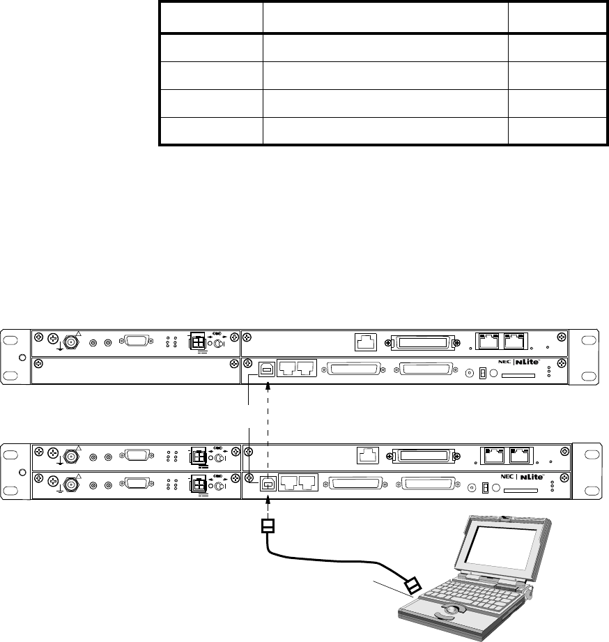
ROI-S07045 INITIAL LINE UP
3-9
3.3 Initial Setting
The initial setup of the MDP/TRP is performed using the PC according to
Table 3-1.
For the details operation of the PC setup for connecting LCT, refer to the
NLite N LCT Operation Manual in Section IV Appendix.
Note: The “Equipment Setup” must be set properly every items
before “Provisioning” setup.
The “Provisioning” setup must be performed based on
the “Equipment Setup”.
When setting or changing Equipment Setup, check the
setting values of all the Provisioning items.
Fig. 3-2 LCT Connection
Table 3-1 Initial Setup Items
Setup Order Setup Item LCT
1. Equipment Setup Chapter 3
2. Date and Time Chapter 6.3
3. Provisioning Chapter 7
4. Relay/House Keeping Chapter 7
LCT ACCESS CABLE
LCT
1+1 CONFIGURATION
1+0 CONFIGURATION
PC for LCT
USB
Note: Use the typical USB shielded cable.
(Do not use the un-shielded cable.)
SELV
!
AUX/ALM
LCT NMS NE SC IN/OUT EOW
PROTECT
CALL MMC
MAINT
MEMORY
MDP
XIF IN XIF OUT
IF IN/OUT TX
RX
RESET
XPIC CTRL XPIC
PWR
TRP
MD/
CBL PWR
PULL
G
G
ALM
100M PORT 1 PORT 2 100M Ns
Ns DS1 IN/OUT
WS IN/OUT
N
SELV
!
AUX/ALM
LCT NMS NE SC IN/OUT EOW
PROTECT
CALL MMC
MAINT
MEMORY
MDP
XIF IN XIF OUT
IF IN/OUT TX
RX
RESET
XPIC CTRL XPIC
PWR
TRP
MD/
CBL PWR
PULL
G
SELV
!
XIF IN XIF OUT
IF IN/OUT TX
RX
RESET
XPIC CTRL XPIC
PWR
TRP
MD/
CBL PWR
PULL
G
G
ALM
100M PORT 1 PORT 2 100M
Ns
Ns
WS IN/OUT Ns
N
DS1 IN/OUT
(Blank)

INITIAL LINE UP ROI-S07045
3-10
3.3.1 Equipment Setup
In initial lineup, the “Equipment Setup” must be performed using LCT.
Chart 3-3 Equipment Setup
Refer to the NLite N LCT Operation Manual in Section IV Appendix. for
the details of “3. EQUIPMENT SETUP”.
• Redundancy Setting
• INTFC Main (WORK)
• INTFC Sub (PROT)
•XPIC Usage *3
• APS Function *3
• Modulation Scheme
• Transmission Capacity
• TX RF Frequency [MHz]
• RX RF Frequency [MHz] *2
• Frame ID
• TX Power Control
•TRP Type *3
• TX SW Type *3
• LAN Port Usage *1
• LAN Capacity1 *1
• LAN Capacity2 *1
• TX Start Frequency [MHz]
• TX Stop Frequency [MHz]
• RX Start Frequency [MHz]
• RX Stop Frequency [MHz]
• Frequency Step [MHz]
• Shift Frequency [MHz]
• Upper/Lower
•Sub Band
Notes:*1 For LAN transmission only.
*2 There is two types TRP for the RX RF Frequency setup
mode.
*3 Indicate only item name, not setting anything.
Type 1.When the transmitting frequency is set, the receiving
frequency is automatically assigned.
Type 2.When the transmitting frequency is set, the receiving
frequency is automatically assigned and assignment of it in
manual is also available.

ROI-S07045 INITIAL LINE UP
3-11
3.3.2 Provisioning
In initial lineup, the “Provisioning” Setup must be performed using LCT.
Chart 3-4 Provisioning
Refer to the NLite N LCT Operation Manual in Section IV Appendix. for
details of the “7. PROVISIONING”.
The Provisioning Setup items are as follows:
Provisioning
• DS1 Setting
• WS Setting
• BER Threshold Setting
• SC Assignment
• LAN Port Setting *1
• TX Power Control *2
• Relay Setting
• TCN Threshold (15min)
• TCN Threshold (1day)
• PMON Select
• In-band Loopback Setting
• Others *3
Notes: *1:For LAN transmission only.
*2:Set to required TX power level in MTPC mode when it
is going to perform the Antenna Orientation.
*3:Optional items
When setting or changing Equipment Setup, check the
setting values of all the Provisioning items.

INITIAL LINE UP ROI-S07045
3-12
3.4 Antenna Orientation
After the initial setup has been completed, an antenna orientation will be
performed between two stations according to the procedures in Chart 3-5.
Chart 3-5 Antenna Orientation
Apparatus:
Digital Multimeter with test leads
Wrench
Headset
Step Procedure
1 Connect the PC to the LCT port on the NLite N MDP using
USB cable, (see Fig. 3-2)
2 At each station, set “Maintenance1” from Maintenance in LCT
Menu,
Note: In Maintenance “On” condition, every external Alarm
outputs, excluding Maintenance/PS/CPU (MDP) ALM,
are masked and remote control can not be performed.
3 Click and select for the following control items in
“Maintenance1”,
Notes: 1. Retain the present status for other control items.
2. When the TX power control mode is set to ATPC, set it to
MTPC and required level for the NLite N link on the
“Equipment Setup” and “Provisioning”.
LCT MENU
Alarm/Status
Equipment Setup
Inventory
AUX I/O
Maintenance
Provisioning
Metering
PMON (History)
Maintenance1
Maintenance2
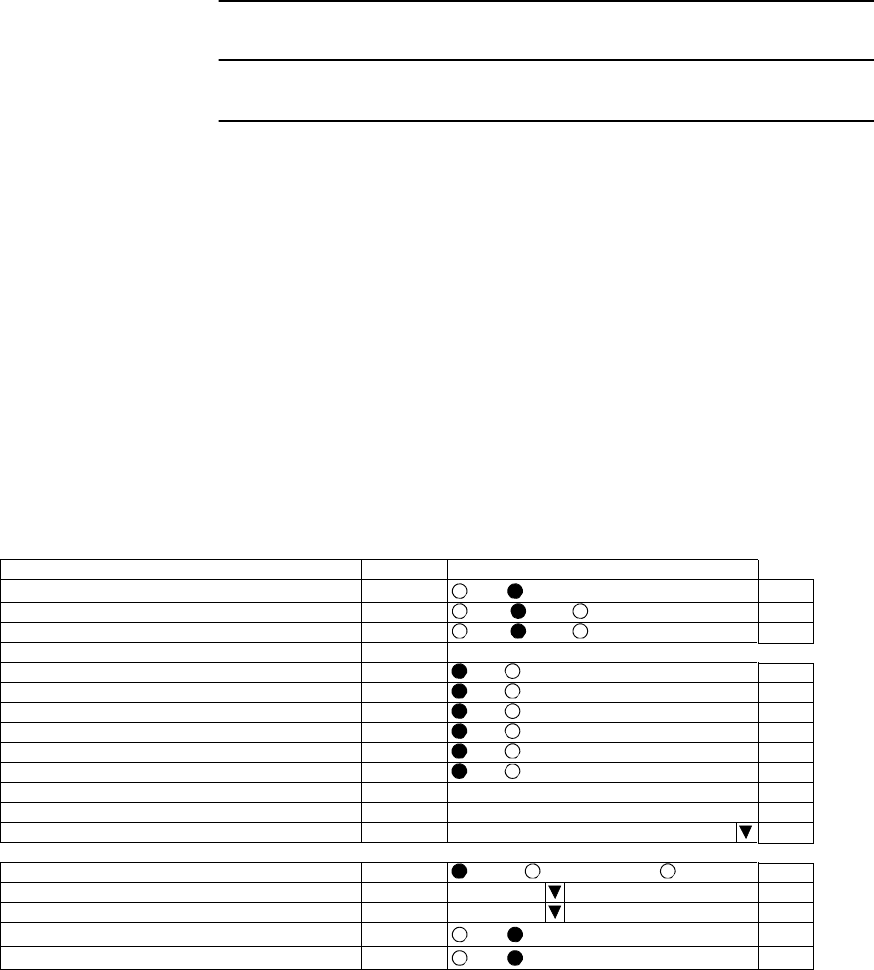
ROI-S07045 INITIAL LINE UP
3-13
Chart 3-5 (Cont’d)
Step Procedure
• TX SW Manual Control: Fix No.1 or No.2
(in 1+1 configuration)
• RX SW Manual Control: Fix No.1 or No.2
(which is the same side fixed by TX SW in
1+1 configuration)
• TX Power Control: MTPC in Equipment Setup
(at opposite site) Required level in Provisioning
• CW Control: When the Antenna Alignment Mode is not
(at opposite site) selected, set manually to On.
• Antenna Alignment Mode: Select On (in 1+0 configuration)
(Set No.1 or No.2 which is the same side
fixed by TX SW and RX SW in 1+1
configuration)
Note: In Antenna Alignment Mode “On” condition, controls
between MDP and TRP are restricted.
--- Maintenance 1 ---
Item Value Setting
Maintenance On
Off On Set
TX SW Manual Control No.1 Auto No.1 No.2 Set
RX SW Manual Control No.1 Auto No.1 No.2 Set
RX SW Maintenance Mode Manual
TX Mute Control(No.1) Off Off On Set
TX Mute Control(No.2) Off Off On Set
CW Control(No.1) Off Off On Set
CW Control(No.2) Off Off On Set
IF Loopback (No.1) Off Off On Set
IF Loopback (No.2) Off Off On Set
Main CH Loopback (Near End) Off Select
Main CH Loopback (Far End) Off Select
LAN Device Reset ... INTFC (1) - Port1 Set
--- Offline Maintenance ---
DADE Adjust ... DADE Offset DADE DADE Off Set
RF Sub Band Select (No.1) ... A Set
RF Sub Band Select (No.2) ... A Set
Antenna Alignment Mode(No.1) On Off On Set
Antenna Alignment Mode(No.2) On Off On Set

INITIAL LINE UP ROI-S07045
3-14
Chart 3-5 (Cont’d)
Step Procedure
4 At receiving station, remove a cap from the RX LEV MON
jack,
5 At each station connect the digital multimeter,
Note: In order to measure exact performance of AGC V, it is
mandatory required to set Antenna Alignment Mode to
ON. The AGC voltage indication is not guaranteed
outside Antenna Alignment Mode.
6 At each station, adjust the azimuth and elevation angle of the
antenna alternately so that the measured voltage becomes
maximum,
Note: The relation of the RX INPUT LEVEL versus RX LEVEL
MON(V) is shown below.
RX LEVEL MON vs RX INPUT LEVEL (Typical)
RX INPUT LEVEL [dBm]
-80 -70 -60 -50 -40 -30 -20
0.5
0
1
1.5
2
2.5
3
3.5
4
4.5
RX LEVEL MON [V]
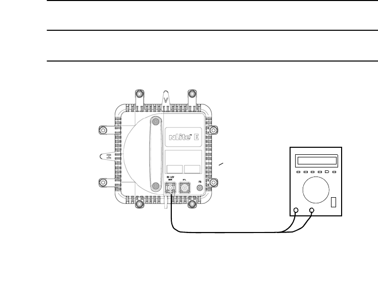
ROI-S07045 INITIAL LINE UP
3-15
Chart 3-5 (Cont’d)
Step Procedure
Fig. 3-3 Antenna Orientation Test Setup
Note: The fixed bolts and nuts to be used for the antenna orientation
differ with antenna bracket types, refer to antenna bracket shown
in Fig. 3-4 (1/4) to (4/4).
RX LEV MON
Notes 1: The RX LEV MON terminal on the TRP (conformed to IEC61169-24).
2: The RX LEV MON terminal must be capped for waterproof.
NHG/NHP Type TRP
DIGITAL MULTIMETER
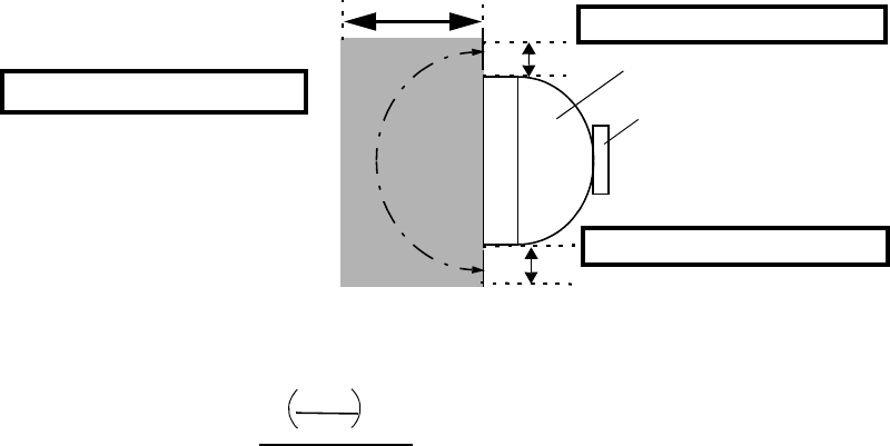
INITIAL LINE UP ROI-S07045
3-16
Safety Guideline for Microwave Radiation Hazard
The Microwave and Millimetre-wave that NLite N series are treating is very small radiation level and
never been reported to effect human health. But advanced countries about health hazard have started to
regulate the radiation levels. In case of EU country, it is specified by EN50385. In order to keep the
regulation, the operator shouldn't work at near parabolic antenna during transmitter activating.
Especially the area in side to front of antenna shows higher radiation level. (please see below figure and
calculation sample 1).
On the other hand, in case of front side of antenna, the power density becomes high level along antenna
beam. Therefore the user of this system should pay attention not to radiate the beam against humans
any time. (Please refer below calculation sample 2)
Hazard Area of Radiation
In addition, the Power density and Field strength level is calculated by equation below.
Where: P = Output power of TRP (dBm),
G = Antenna Gain (dBi),
(in consideration of the angle from antenna)
K = Reflection factor =2.56 (given),
R = Distance between Human and Antenna (m)
Calculation example 1, (90 degree side of antenna)
NLite N = 18 GHz/+23 dBm,
Antenna diameter = 0.6 m,
0 degree antenna gain = 39 dBi,
90 degrees side antenna gain = −24 dBi, (90 degrees attenuation = −63 dB),
Distance = 0.1 m
Power density S (mW/cm2) = 0.0016 ≤ 0.01 (European safety guideline)
Calculation example 2, (0 degree, front side of antenna)
NLite N = 7 GHz/+27 dBm,
Antenna diameter = 1.8 m,
0 degree antenna gain = 40 dBi,
Distance = 100 m
Power density S (mW/cm2) = 0.01 => Equal to European safety guideline
TRP
- 90 to +90
degrees
ANTENNA
0.1m for Calculation example 1
0.1m for Calculation example 1
100m for Calculation example 2
10 × K
Power density S (mW/cm2) =
40 × π × R2
P+G−30
10

ROI-S07045 INITIAL LINE UP
3-17
Chart 3-5 (Cont’d)
Step Procedure
ANTENNA DIRECTO MOUNTING TYPE
A. USING ANDREW VHLP TYPE BRACKET
Azimuth Angle Adjustment
6-1 Loosen bolts (1 in Fig. 3-4 (1/4) A),
6-2 Adjust the azimuth angle by adjusting bolt (2 in Fig. 3-4 (1/4)
A),
6-3 Secure bolts loosened in step 6-1,
Elevation Angle Adjustment
6-4 Loosen bolts (3 in Fig. 3-4 (1/4) A),
6-5 Adjust the elevation angle by adjusting bolt (4 in Fig. 3-4 (1/4)
A)
6-6 Secure bolts loosened in step 6-4,
B. USING RFS SB1 TYPE BRACKET
Azimuth Angle Adjustment
6-7 Loosen nuts (1 in Fig. 3-4-B),
6-8 Adjust the azimuth angle by adjusting the nuts (2 in Fig. 3-4
(1/4) B),
6-9 Secure nuts loosened in step 6-7,
Elevation Angle Adjustment
6-10 Loosen bolt(s) (3 in Fig. 3-4 (1/4) B),
6-11 Adjust the elevation angle by adjusting the nuts (4 in Fig. 3-4
(1/4) B),
6-12 Secure nut loosened in step 6-7,
6-13 Secure nuts loosened in step 6-10.

INITIAL LINE UP ROI-S07045
3-18
Chart 3-5 (Cont’d)
Step Procedure
C. USING RFS C-Mount TYPE BRACKET
Azimuth Angle Adjustment
6-14 Loosen 3 bolts (1 in Fig. 3-4 (2/4)),
6-15 Adjust azimuth angle by adjusting bolt (2 in Fig. 3-4 (2/4)),
6-16 Secure nuts loosened in step 6-14,
Elevation Angle Adjustment
6-17 Loosen 4 bolts (3 in Fig. 3-4 (2/4)),
6-18 Adjust elevation angle by adjusting bolt (4 in Fig. 3-4 (2/4)),
6-19 Secure bolts loosened in step 6-17,
7 At each station, restore the “Antenna Alignment Mode” to “off”
using the LCT,
8 At each station, reset control items to original using LCT,
9 At each station, restore the “MAINT Mode” to “off” position
using the LCT,
10 At each station, disconnect the digital multimeter Monitor from
the RX LEV MON connector,
11 At each station, reconnect the cap removed in step 4,
Note: The RX LEV MON connector must be capped for
waterproof.

ROI-S07045 INITIAL LINE UP
3-19
Chart 3-5 (Cont’d)
Step Procedure
XPD Adjustment (For Antenna Direct Mounting Type)
Note: The XPD adjustment using cross-polarization signal should be
done more carefully than using co-polarization signal because
XPD changes sharply in the axial direction.
1’ Loosen three screws (SCREW1, 2 and 3 in Fig. 3-4 (3/4)) and
rotate antenna (connected OMT/TRP) so that the RX LEVEL
MON indicates the maximum value at the TRP of the Main
Master and Sub Master channels,
2’ At opposite station, turns the TRP of the Sub Master channel
power OFF (for both No.1 and No.2 Sub Master channels in 1+1
system),
3’ In this conditions, check the RX LEVEL MON indication value
for XPD at the TRP of the Sub Master channel,
4’ Confirm that the XPD is more than 25 dB, if not, repeat
Azimuth Angle, Elevation Angle and XPD Adjustment,
5’ At opposite station, turns the TRP of the Sub Master channel
power ON,
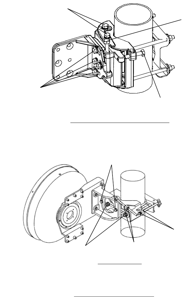
INITIAL LINE UP ROI-S07045
3-20
Fig. 3-4 Location of Adjusting Nuts and Bolts (1/4)
1. Loosen for adjusting azimuth
2. Adjust azimuth
3. Loosen (1/4 TURN) bolts for adjusting elevation
0.3 φ m Antenna
B. RFS SB1 TYPE BRACKET
4. Adjust elevation
2. Adjust azimuth
1. Loosen (1/2 turn) bolts
for adjusting azimuth (top
and bottom)
3. Loosen (1/2 turn) bolts
for adjusting elevation
4. Adjust elevation
A. ANDREW VHLP TYPE BRACKET
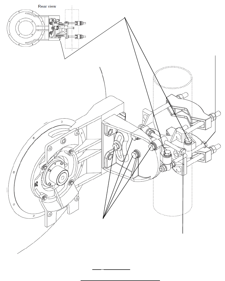
ROI-S07045 INITIAL LINE UP
3-21
Fig. 3-4 Location of Adjusting Nuts and Bolts (2/4)
1. Loosen (1/4 turn) bolts
for adjusting azimuth
0.6 φ m Antenna
C. RFS C-Mount TYPE BRACKET
3. Loosen (1/4 turn) bolts
for adjusting elevation.
2. Adjust azimuth.
4. Adjust elevation.
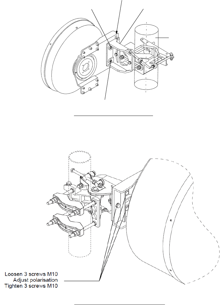
INITIAL LINE UP ROI-S07045
3-22
Fig. 3-4 Location of Adjusting Nuts and Bolts (3/4)
POLE
SCREW 2
SCREW 3
SCREW 1
ROTATION
INDICATOR
A. RFS SB1 TYPE BRACKET
B. RFS C-Mount TYPE BRACKET

ROI-S07045 INITIAL LINE UP
3-23
Chart 3-5 (Cont’d)
Step Procedure
WAVEGUIDE CONNECTION TYPE
Azimuth Angle Adjustment (Waveguide Connection Type)
Note: Take care that the flexible waveguide is not forcedly twisted by
rotating the antenna.
When the HS/SD system is configured, alternately switchover
the transmitter to the other channel (No.1 or No.2) at the
opposite station and repeat adjustment of elevation and azimuth
to obtain satisfactory results in both No.1 and No.2 CH. (Refer
to Chart 3-7 for TX SW/RX SW Manual Switchover Operation).
1’ Loosen all strut attachment hardware,
2’ Loosen bolts indicated by arrows in Fig. 3-4 (4/4)-A,
3’ Loosen jam nuts and rotate turnbuckle-1 in Fig. 3-4 (4/4)-A so
that the RX LEVEL MON voltage obtains the maximum value,
4’ Carefully, tighten turnbuckle-1 jam nuts and bolts indicated by
arrows in Fig. 3-4 (4/4)-A to hold the adjustment,
Elevation Angle Adjustment (Waveguide Connection Type)
5’ Make sure that all strut attachment hardware is loosened,
6’ Loosen bolts indicated by arrows in Fig. 3-4 (4/4)-B,
7’ Loosen jam nuts and rotate turnbuckle-2 in Fig. 3-4 (4/4)-B so
that the RX LEVEL MON voltage obtains the maximum value,
8’ Carefully, tighten turnbuckle-2 jam nuts and bolts indicated by
arrows in Fig. 3-4 (4/4)-B,
XPD Adjustment (Waveguide Connection Type)
Note: This XPD adjustment using cross-polarization signal should be
done more carefully than using co-polarization signal because
XPD changes sharply in the axial direction.
9’ At opposite station, turns the TRP of the Sub Master channel
power OFF (for both No.1 and No.2 Sub Master channels in 1+1
system),
10’ In this conditions, check the RX LEVEL MON indication value
for XPD at the TRP of the Sub Master channel,

INITIAL LINE UP ROI-S07045
3-24
Chart 3-5 (Cont’d)
Step Procedure
11’ Confirm that the XPD is more than 25 dB, if it is not obtained,
repeat Azimuth Angle, Elevation Angle for the XPD
Adjustment,
12’ Tighten all strut attachment hardware, turnbackle jam nuts and
bolts indicated by arrows in Fig. 3-4 (4/4) A and Fig. 3-4 (4/4)
B,
13’ At opposite station, turns the TRP of the Sub Master channel
power ON (for both No.1 and No.2 slave channels in 1+1
system),
12 At each station, disconnect the digital multimeter from the RX
LEV MON connector,
13 At each station, reconnect the cap removed in step 4,
Note: The RX LEV MON connector must be capped for
waterproof.
14 At each station, restore the “Antenna Alignment Mode” to “off”
position using the LCT,
15 At the Main Master station, when the TX power control is
operated in ATPC, restore the TX Power Control item of System
Configuration changed in step 1 to “ATPC” using the LCT,
16 At the Main Master, when the TX power control is operated in
MTPC, restore MTPC TX PWR item of “Provisioning Data”
changed in step 2 to original setting value using the LCT.
17 At each station, reset Maintenance to “OFF”.
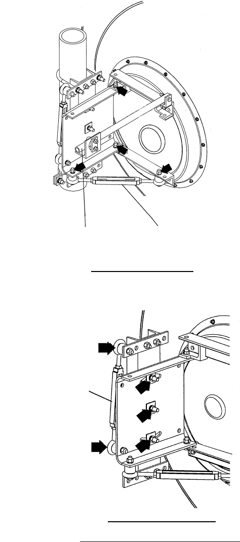
ROI-S07045 INITIAL LINE UP
3-25
Fig. 3-4 Location of Adjusting Nuts and Bolts (4/4)
STRUT TURNBUCKLE-1
A. Azimuth Adjustment
TURNBUCKLE-2
ANDREW VHLP4 TYPE BRACKET
B. Elevation Adjustment

INITIAL LINE UP ROI-S07045
3-26
3.5 Lineup Test
Line up test items for between two stations are listed in Table 3-2.
Note: *1 Chart 3-7 is described about Manual Switchover Operation.
*2 Chart 3-8 is needed only when INTFC is Out-phase in 1+1
configuration.
*3 After the initial lineup has been finished, clear PMON and
RMON data for the start of service operation.
Chart 3-6 Orderwire Test
Step Procedure
1 Connect headset to the EOW jack on the MDP,
2 Press the CALL button on the MDP,
Requirement: At the opposite station, the buzzer on the MDP
sounds,
3 Check that the orderwire can be used between two stations with
headsets,
4 Disconnect headset from EOW jack on the MDP at each station.
Table 3-2 Lineup Test Items
Item Chart No.
Orderwire Test Chart 3-6
TX/RX SW Switchover Operation Chart 3-7 *1
DADE Adjust Chart 3-8 *2
Meter Reading Chart 3-9
PMON Clear Chart 3-13 *3
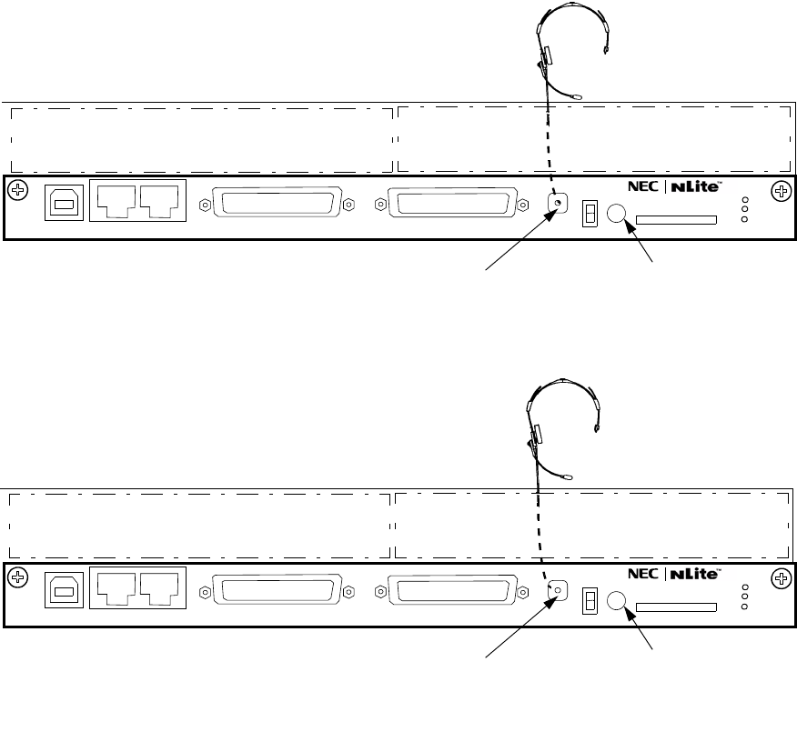
ROI-S07045 INITIAL LINE UP
3-27
Fig. 3-5 OW Test Setup for MDP
AUX/ALM
NMS NE SC IN/OUT EOW
PROTECT
CALL MMC
MAINT
MEMORY
MDP
LCT
EOW CALL
LOCAL STATION
N
AUX/ALM
NMS NE SC IN/OUT EOW
PROTECT
CALL MMC
MAINT
MEMORY
MDP
LCT
EOW CALL
OPPOSITE STATION
N
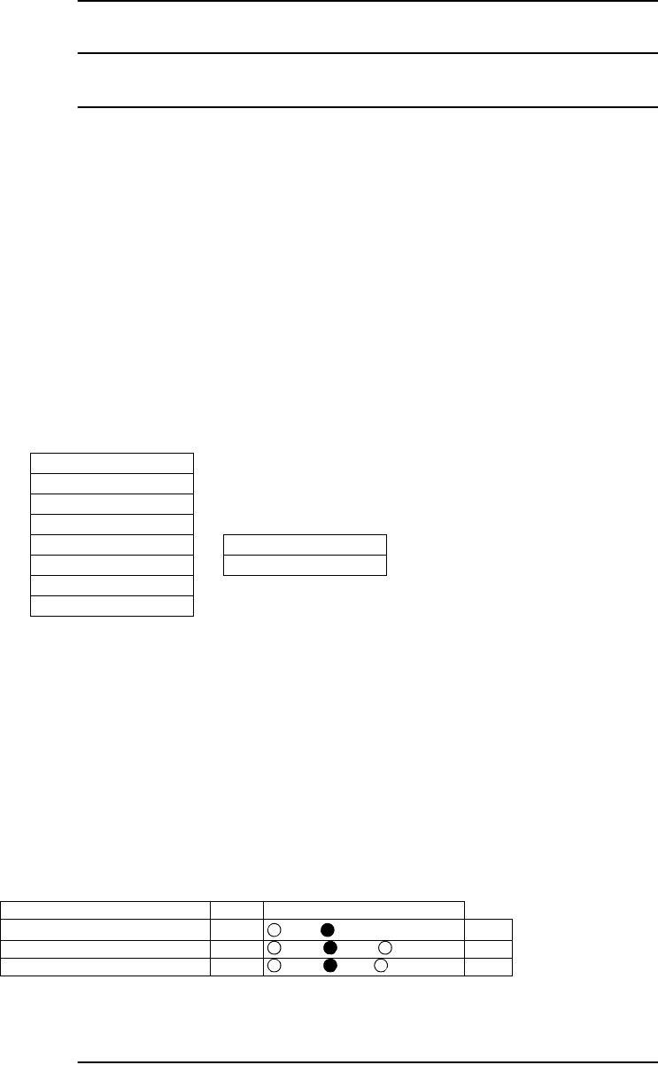
INITIAL LINE UP ROI-S07045
3-28
Chart 3-7 TX/RX SW Switchover Operation
Step Procedure
The TX/RX SW switchover operation is performed only in 1+1
configuration.
1 Connect the PC to the LCT port on the NLite N MDP using
USB cable, (see Fig. 3-2)
2 Enter Login name “Admin”, enter Admin password and press
the “Login” button,
3 LCT Open window will be displayed, then click “Maintenance”
button in the LCT MENU, select “Maintenance1” on
background menu,
4 Select “On” of the Maintenance setting button and click on
“Set” button,
5 Select “No.1” or “No.2” of the TX SW setting button and click
on “Set” button,
6 Select “No.1” or “No.2” of the RX SW setting button and click
on “Set” button,
7 Check that the “Value” box for each item turned to the required
status.
LCT MENU
Alarm/Status
Equipment Setup
Inventory
AUX I/O
Maintenance
Provisioning
Metering
PMON (History)
Maintenance1
Maintenance2
--- Maintenance 1 ---
Item Value Setting
Maintenance On
Off On Set
TX SW Manual Control No.1 Auto No.1 No.2 Set
RX SW Manual Control No.1 Auto No.1 No.2 Set
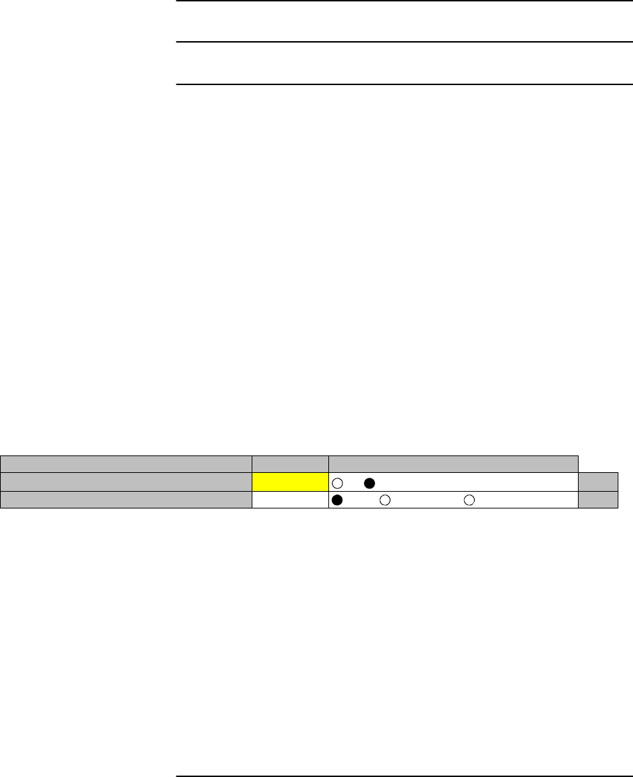
ROI-S07045 INITIAL LINE UP
3-29
Chart 3-8 DADE Adjustment
Step Procedure
Note: The DADE control applies in 1+1 configuration to adjust
delay time for RX hitless switching when the INTFC
status is indicated Outphase.
1 Connect the USB cable to the USB port of PC and the LCT port
of the MDP (see Fig. 3-2),
2 Login to LCT using Internet Explorer,
3 Enter Login name “Admin”, enter Admin password and press
the “Login” button,
4 LCT Open window will be displayed, then click “Maintenance”
button in the LCT Menu area, select “Maintenance1” on
background menu,
5 Select “DADE Adjust” on the “Maintenance1” table,
6 Click on setting button “DADE”, “Off set DADE” or “DADE
Off” and click on “Set” button,
Note: The DADE adjustment is needed in initial lineup or when the IF CABLE is replaced. It
is not needed readjustment when the INTFC status is indicated In-phase. The setting
conditions are as follows:
DADE: Automatically adjust delay time based on either No.1 signal or No.2
signal which it is selected by RX SW under the Outphase condition of the
INTFC status. The DADE control is processed assuring no interruption of
traffic.
Offset DADE:Automatically adjust delay time based on either No.1 signal or No.2 signal
which it is selected by RX SW under the Outphase condition of the INTFC
status. Since the offset memory minimizes the latency delay, traffic
interruption occurs at that moment. This Offset DADE controls the delay
time difference to a minimum than DADE control.
DADE off: Set when DADE function is not used. For particularly, when low bit rate (10
to 20 MB) transmission is applied to the system, the DADE control is not
required.
---Maintenance1---
Item Value Setting
Maintenance On Off On Set
DADE Adjust --- DADE Offset DADE DADE Off Set

INITIAL LINE UP ROI-S07045
3-30
Chart 3-9 Meter Reading
Step Procedure
1 Connect the PC to the LCT port on the NLite N MDP using
USB cable, (see Fig. 3-2)
2 Enter Login name “Admin”, enter Admin password and press
the “Login” button,
3 Click “Metering” button in LCT Menu,
4 Then, the values of Metering items are displayed as follows:
1+1 Configuration
1+0 Configuration
LCT MENU
Alarm/Status
Equipment Setup
Inventory
AUX I/O
Maintenance
Provisioning
Metering
PMON (History)
----Metering---
No.1 No.2
TX Power [dBm]*1 +19 +19
RX Level [dBm] -49.5 -49.7
Power Supply [V] *2 -45 -45
BER *3 0.0E-10 Calculating
----Metering---
TX Power [dBm]*1 +19
RX Level [dBm] -50
Power Supply [V] *2 -45
BER *3 1.10E-10

ROI-S07045 INITIAL LINE UP
3-31
Chart 3-9 (Cont’d)
Step Procedure
Notes:*1: TX POWER Level is indicated in 1 dB step.
The TX Power varies depending on the propagation
condition within setup ATPC range in provisioning,
therefore, TX Power may be displayed within limited values
listed in Table 3-3. Add attenuation value for Max. and Min.
level when additional attenuator is used.
*2: Power supply voltage of the TRP input varies depending on
the IF cable length.
*3: During total number of erroneous bits and total number of
correctly received bits are calculating, “Calculating” and
*E-** are displayed.
Note: ( ) shows the values with additional attenuator.
Table 3-3 TX Power Output Level
Modulation
Mode Frequency Band (GHz) 5.8G
(EHG) L6G U6G
(EHG) 10.5G 11G 18G 23G 38G
QPSK Output Power Max. (dBm)
(at ATPC 0 dB) +21 +29 +21 +25 +25 +24 +24 +18
Output Power Min. (dBm)-9-1-9-5-5-6-6-7
Additional attenuator (dB) NA NA
16QAM Output Power Max. (dBm)
(at ATPC 0 dB) +21 +27 +21 +21.5 +21.5 +22 +22 +14.5
Output Power Min. (dBm) -3 +3 -3 -2.5 -2.5 -2 -2 -9.5
Additional attenuator (dB) NA NA
32QAM Output Power Max. (dBm)
(at ATPC 0 dB) +21 +25 +21 +21 +21 +19 +19 +14.5
Output Power Min. (dBm) -2 +2(-3) -2(-7) -2(-7) -2(-7) -4(-9) -4(-9) -8.5
Additional attenuator (dB) 5 NA
64QAM Output Power Max. (dBm)
(at ATPC 0 dB) +21 +25 +21 +21 +21 +19 +19 +14.5
Output Power Min. (dBm) +1(-4) +5(0) +1(-4) +1(-4) +1(-4) -1(-6) -1(-6) -5.5
Additional attenuator (dB) 5 NA
128QAM Output Power Max. (dBm)
(at ATPC 0 dB) +21 +25 +21 +21 +21 +19 +19 +14.5
Output Power Min. (dBm) +1(-4) +5(0) +1(-4) +1(-4) +1(-4) -1(6) -1(-6) -5.5
Additional attenuator (dB) 5 NA
Tolerance (dB) ±3 (except additional attenuator)

INITIAL LINE UP ROI-S07045
3-32
Table 3-4 ALL INOOR TR Unit Tx Power Output Level
Modulation
Mode Frequency Band (GHz)
(TX Power at TR Unit Out)
L6G U6G 11G
High
Power STD
Power High
Power STD
Power High
Power
32QAM Output Power Max. (dBm)
(at ATPC 0 dB) +32.5 +29.5 +32.5 +29.5 +30
Output Power Min. (dBm) +12.5 +9.5 +12.5 +9.5 +10
Additional attenuator (dB) 5
64QAM Output Power Max. (dBm)
(at ATPC 0 dB) +32.5 +29.5 +32.5 +29.5 +30
Output Power Min. (dBm) +12.5 +9.5 +12.5 +9.5 +10
Additional attenuator (dB) 5
128QAM Output Power Max. (dBm)
(at ATPC 0 dB) +32.5 +29.5 +32.5 +29.5
Output Power Min. (dBm) +12.5 +9.5 +12.5 +9.5
Additional attenuator (dB) 5
Tolerance (dB) ±3 (except additional attenuator)

ROI-S07045 INITIAL LINE UP
3-33
3.6 TRP Mounting/Demounting (ALL INDOOR TRP)
Install the equipment in the place where it is not restricted access
location regulated with UL60950-1.
The installation procedure for TRP is shown in Chart 3-10. The TRP
should be installed in the radio station indoor.
Chart 3-10 Mounting Method for TRP (ALL INDOOR TRP)
Step Procedure
1 Be careful and mount TRP onto the rack using two persons.
Note: When the change of the connecting direction of the transducer for
the waveguide is necessary, that is possible using the same SJ
cables. Refer to the following procedure.
2 When the waveguide will be connected from the left side of the
equipment, different SJ cables. provide for the transducer
connection.
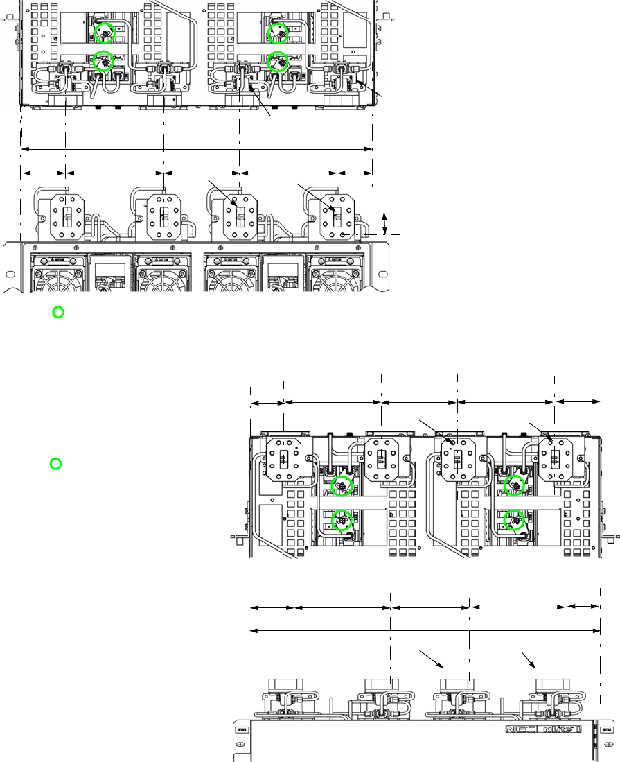
INITIAL LINE UP ROI-S07045
3-34
121 mm
435 mm
42.3 mm
(Front View)
(Down View)
121 mm 42.3 mm
(Down View)
(Front View)
121 mm 55.7 mm
Waveguide Connection in Up Direction
Waveguide Connection in Rear Direction
(1) Using torque wrench, loosen
connectors of the SJ cable(s)
connected between the BR
CKT and transducer.
(The same SJ-cable(s) are
reused.)
(2) Disconnect the SJ cable from
transducer side only.
(3) Loosen two screw bolts
holding the transducer and
remove the transducer.
(4) Turn the transducer and fit
the through-hole to the
holding screw hole.
(5) Tighten two screw bolts to
fix the transducer to the
shelf,
(6) Connect the SJ cable to the
transducer and tighten the SJ
cable connectors with the
torque wrench,
Note: Being careful, tighten
alternately and gradually
either end connectors of the SJ
cable.
Tightening torque: 0.6 N·m.
Note: : SJ cable connector-lock metal and screw bolt.
Note: :SJ cable connector-lock metal
and screw bolt.
(17 in.)
(4.8 in.) (1.7 in.)
(4.8 in.) (2.2 in.)
SD RX
MAIN
TX/RX
MAIN
TX/RX
SD RX
SD RX MAIN TX/RX
SD RX MAIN TX/RX
121 mm
(1.7 in.)
(4.8 in.)
(4.8 in.)
95 mm
(3.7 in.)
55.7 mm
(2.2 in.)
28.8 mm
(1.1 in.)
121 mm
(4.8 in.)
95 mm
(3.7 in.)
55.7 mm
(2.2 in.)
435 mm
(17 in.)
95 mm
(3.7 in.)
121 mm
(4.8 in.)
(1.7 in.)
42.3 mm
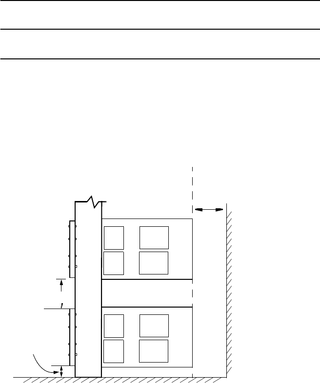
ROI-S07045 INITIAL LINE UP
3-35
Chart 3-10 (Cont’d)
Step Procedure
3 Align the TRP to the mounting position on the 19-inch rack.
Note: To mount the TRP in a 19-inch rack above other
equipment, leave space for two rack units at the bottom to
allow heat from the NLite N to radiate.
4 Holding both handles and bottom of the TRP using two persons,
mount it into the rack,
5 Using a screw driver, tighten four screw bolts to fix the TRP at
left and right sides,
At least
two rack units
More than
200 mm
(8 in.)
At least
one rack unit
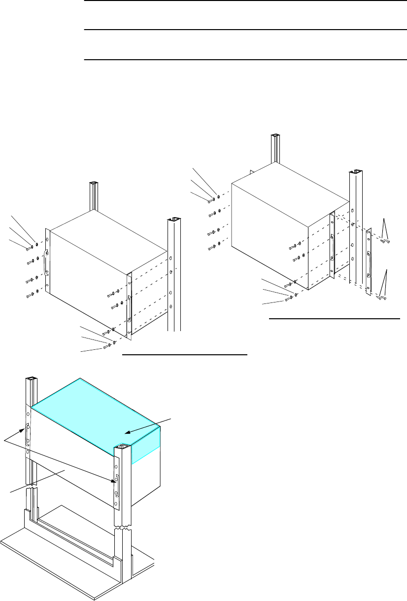
INITIAL LINE UP ROI-S07045
3-36
Chart 3-10 (Cont’d)
Step Procedure
6 When the TRP is close to the wall (within 200 mm (8 in.)),
move two fixture brackets to center position on both sides of the
equipment. (four screws are used for each side)
SCREW
FLAT WASHER
SCREW
FLAT WASHER
SPRING WASHER
SPRING WASHER
SCREW
FLAT WASHER
SCREW
FLAT WASHER
SPRING WASHER
SPRING WASHER
Mounting at Front Position
Mounting at Center Position
SCREW
SCREW
ALL INDOOR TRP
HOT SURFACE
Caution: Install the equipment in the place that is a
restricted access location in compliance
with UL60950-1.
When the TRP is installed in a place of
unrestricted access, open space above TRP
is more than two rack unit (approximately
90 mm). Also, keep the environment
temperature lower than +104°F (+40°C).
HANDLE

ROI-S07045 INITIAL LINE UP
3-37
Chart 3-10 (Cont’d)
Step Procedure
7 Connect the frame ground cable (*) to the “FG” terminals on the
TR UNIT and the MDP,
8 Connect to between the RF SW CTRL connectors on the I/O
BOARD (TRP) and the CTRL UNIT (MDP) using an exclusive
cable,
9 Connect to between the CLUSTER ALM/AUX connectors on
the I/O BOARD (TRP) and the CTRL UNIT (MDP) using an
exclusive cable,
10 Connect an IFL cable to between IFL connectors on the TR
UNIT and MDP,
11 Connect signal cables to the appropriate connector on the I/O
BOARD and the CTRL UNIT using,
12 Connect the power supply cable to the DC IN connector on the
TR UNIT.
13 Connect the power supply cable to the SEL V connector on the
MDP,
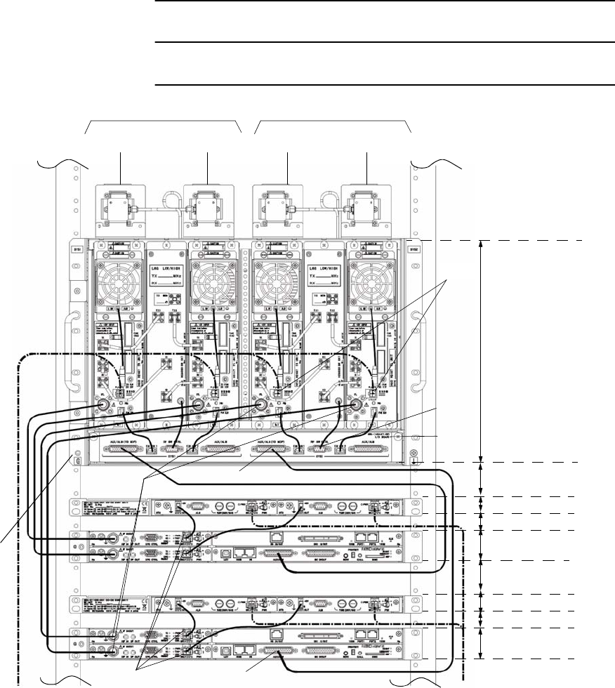
INITIAL LINE UP ROI-S07045
3-38
Chart 3-10 (Cont’d)
Step Procedure
FG(*)
IFL
RF SW
SEL V
DC IN
AUX/ALM (TO MDP) at least 1 Rack Unit
7 Rack Unit
1 Rack Unit
0.5 Rack Unit
0.5 Rack Unit
1 Rack Unit
SD RX * MAIN TX/RX
SD RX * MAIN TX/RX
SYS 1 SYS 2
Note:(*)5 mm square cable (more than 2.5 mm diameter cable) (AWG#10 cable) is recommended
for frame ground. The proper press fix terminal tool shall be used.
CTRL
at least 0.5 Rack Unit
at least 1 Rack Unit
at least 0.5 Rack Unit
I/O
BOARD
AUX/ALM
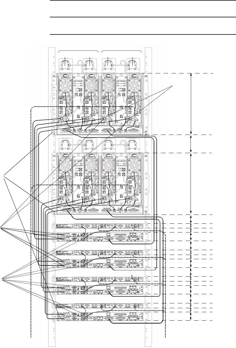
ROI-S07045 INITIAL LINE UP
3-39
Chart 3-10 (Cont’d)
Step Procedure
SD RX * MAIN TX/RXSD RX * MAIN TX/RX
SYS 1 SYS 2
FG(*)
IFL
DC IN
7 Rack Unit
SEL
at least
2 Rack Unit
7 Rack Unit
at least
1 Rack Unit
0.5 Rack Unit
at least 0.5 Rack Unit
1 Rack Unit
at least
1 Rack Unit
0.5 Rack Unit
at least 0.5 Rack Unit
1 Rack Unit
at least
1 Rack Unit
0.5 Rack Unit
at least 0.5 Rack Unit
1 Rack Unit
at least
1 Rack Unit
0.5 Rack Unit
at least 0.5 Rack Unit
1 Rack Unit
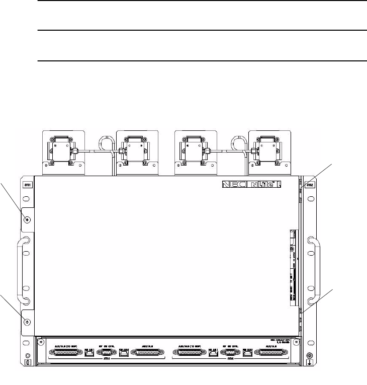
INITIAL LINE UP ROI-S07045
3-40
Chart 3-10 (Cont’d)
Step Procedure
14 Attach the front cover to the equipment with two hinges and
tighten two screws.
Front Cover
Screw for
Front Cover
Screw for
Hinge
Hinge

ROI-S07045 INITIAL LINE UP
3-41
3.6.1 TRP Demounting (ALL INDOOR TRP)
For demounting the TRP (if necessary), use the following procedure.
Chart 3-11 TRP Demounting
Step Procedure
1 Remove front cover from the TRP,
2 Turn off the power switch of the MDP No.1 and No.2,.
3 Turn off the DC power to the TRP and disconnect power supply
cables from the DC IN jack on the TR UNIT No.1 and No.2,
4 Disconnect IFL cables from the TR UNIT No.1 and No.2,
5 Disconnect a cable from the RF SW CTRL connector on the I/O
BOARD,
6 Disconnect a cable from the CLUSTER ALM/AUX connector
on the I/O BOARD,
7 Disconnect waveguide feeder from the transducer,
8 Disconnect ground cables from “FG” terminal on the TRP,
9 Remove the four (or eight) holding bolts from both sides of the
TRP,
10 Remove the TRP from the rack.
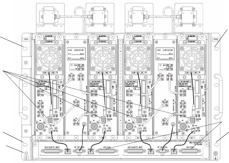
INITIAL LINE UP ROI-S07045
3-42
Note: Before demounting the TRP equipment from the 19 inch rack,
wait for a while until cool down the TRP.
SCREW
SCREW
DC IN
SCREW
FG
SCREW
AUX/ALM
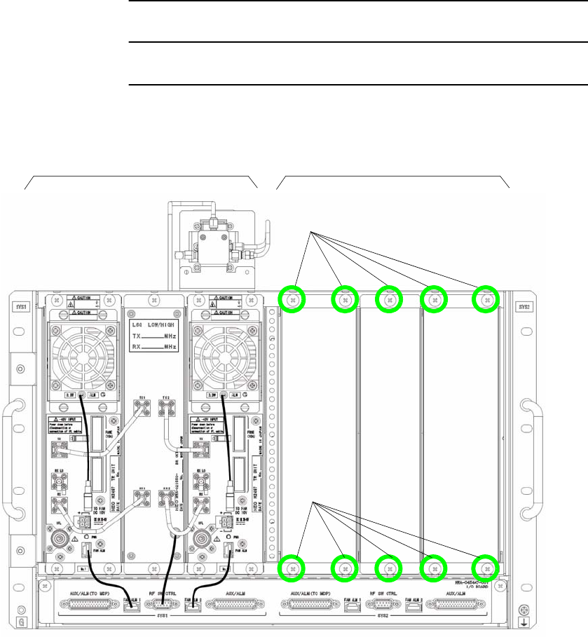
ROI-S07045 INITIAL LINE UP
3-43
3.7 System Expansion (ALL INDOOR TRP)
The expansion procedure for the TRP is explained in Chart 3-12. The TRP
may be expanded in the SYS2.
Chart 3-12 Expansion Method for TRP (ALL INDOOR TRP)
Step Procedure
1 Loosen screws of the blank panels of the SYS2 of the TRP to be
expanded,
SYS 1 SYS 2
Loosen screws to remove BLK panel.
Loosen screws to remove BLK panel.
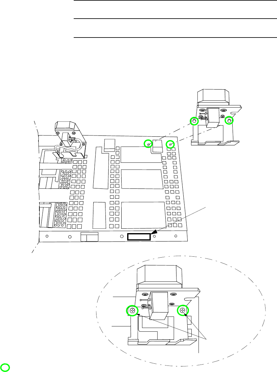
INITIAL LINE UP ROI-S07045
3-44
Chart 3-12 (Cont’d)
Step Procedure
2 Using a screw driver, tighten two screws to fix the transducer for
SYS2 at the rear side of the shelf,
3 Put the name plate on the shelf as shown in figure below,
Down View
NAME PLATE
TRANSDUCER
Fixing
Transducer
: Tighten screws, using screw driver.
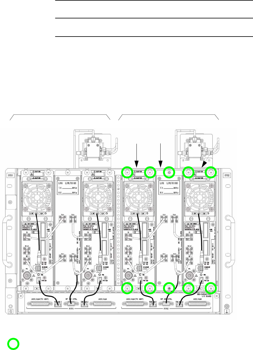
ROI-S07045 INITIAL LINE UP
3-45
Chart 3-12 (Cont’d)
Step Procedure
4 Align the TR unit and BR CKT to the mounting position in the
SYS 2,
5 Using a screw driver, tighten screws at the upper position and
lower position of the unit,
No.1 TRP BR CKT No.2 TRP
SYS 1 SYS 2
:Tighten screws, using screw driver.
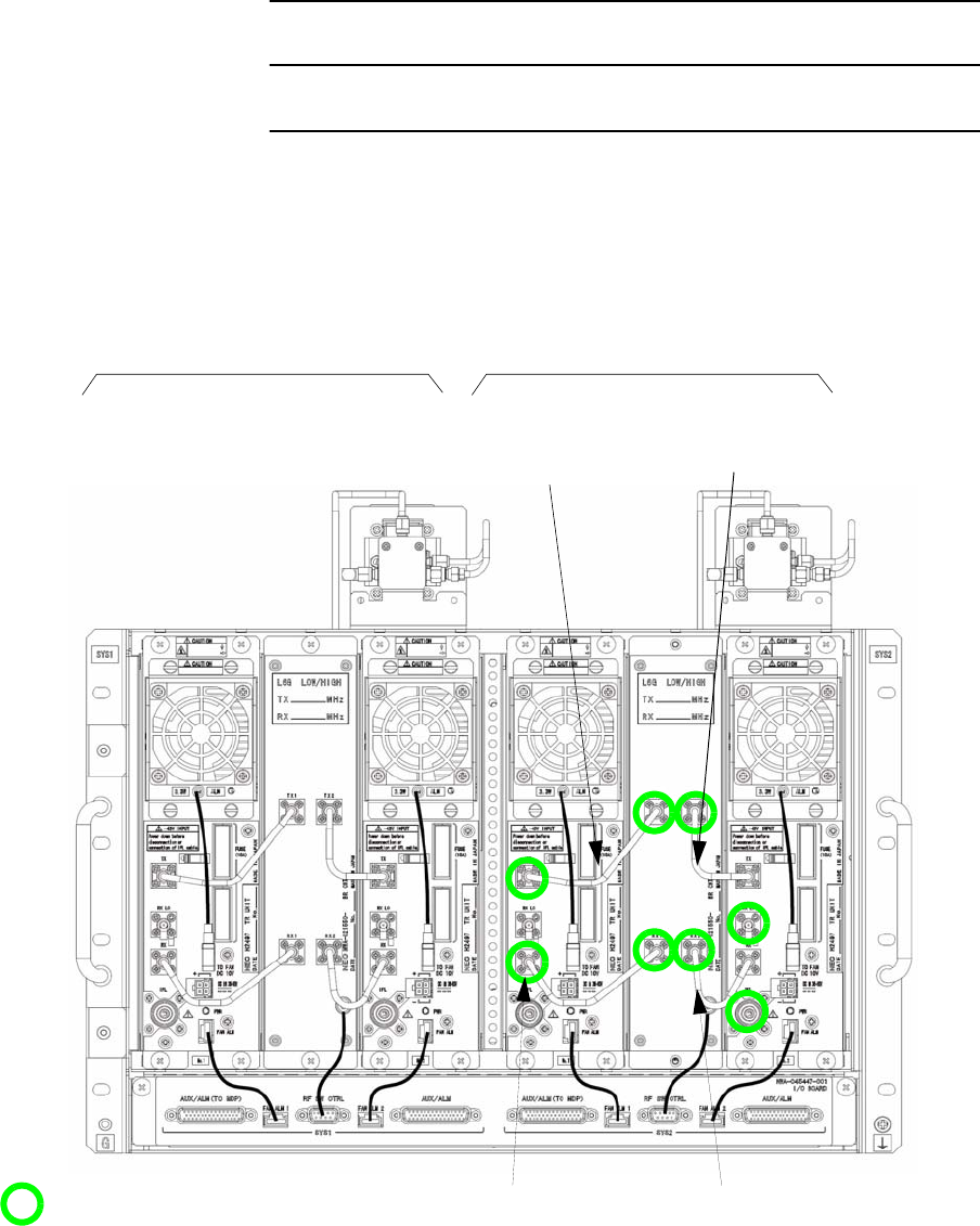
INITIAL LINE UP ROI-S07045
3-46
Chart 3-12 (Cont’d)
Step Procedure
6 Connect SJ cables between TR unit and BR CKT as shown in
figure below,
7 Using torque wrength, thighten SJ cable connectors,
TX1 (BR CKT)
SYS 1 SYS 2
TX1 (BR CKT)
TX (No.1 TRP) TX (No.2 TRP)
TX1 (BR CKT)
TX (No.1 TRP)
TX1 (BR CKT)
TX (No.2 TRP)
: Tighten screws, using screw driver.
Note: Being careful, tighten altenately and
gradually either and connections of the SJ
cable. Tightening torque: 0.6 N•m.
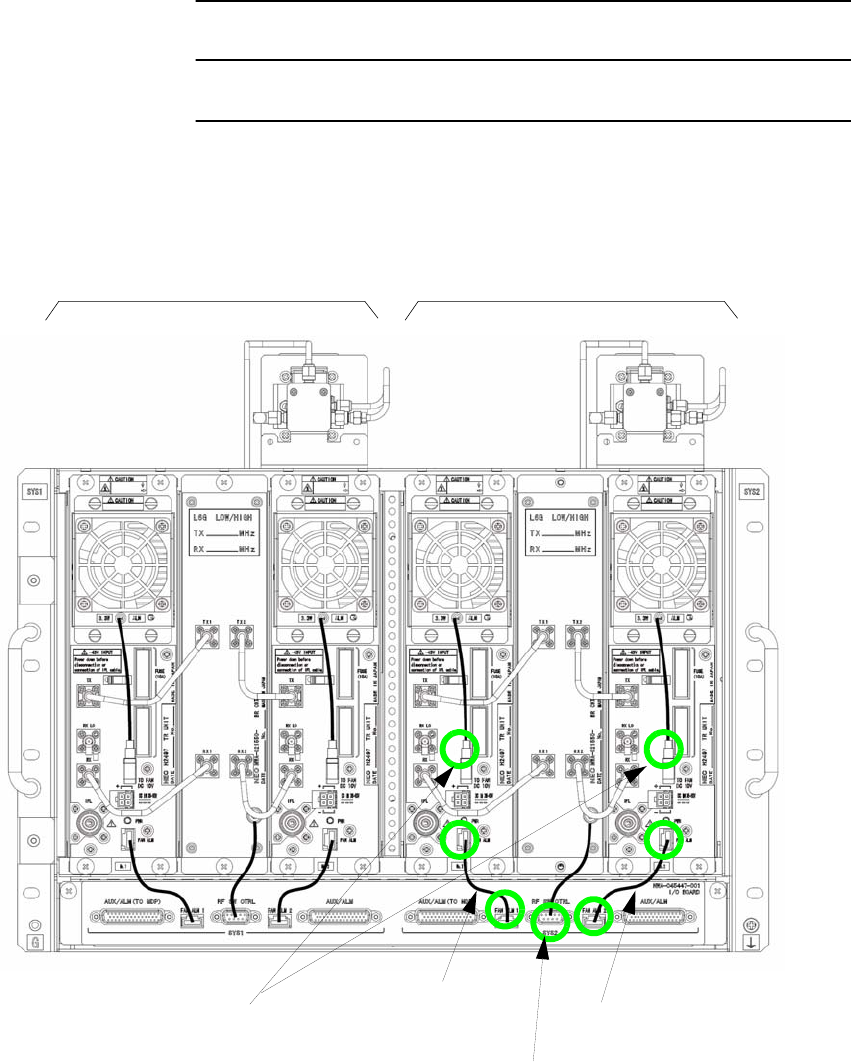
ROI-S07045 INITIAL LINE UP
3-47
Chart 3-12 (Cont’d)
Step Procedure
8 Connect FAN power supply cable, FAN ALM cable and RF SW
CTRL cable to corresponding connector as shown in figure
below,
SYS 1 SYS 2
FAN ALM1
FAN ALM
FAN ALM2
FAN ALM
To FAN DC 10V
RF SW CTRL
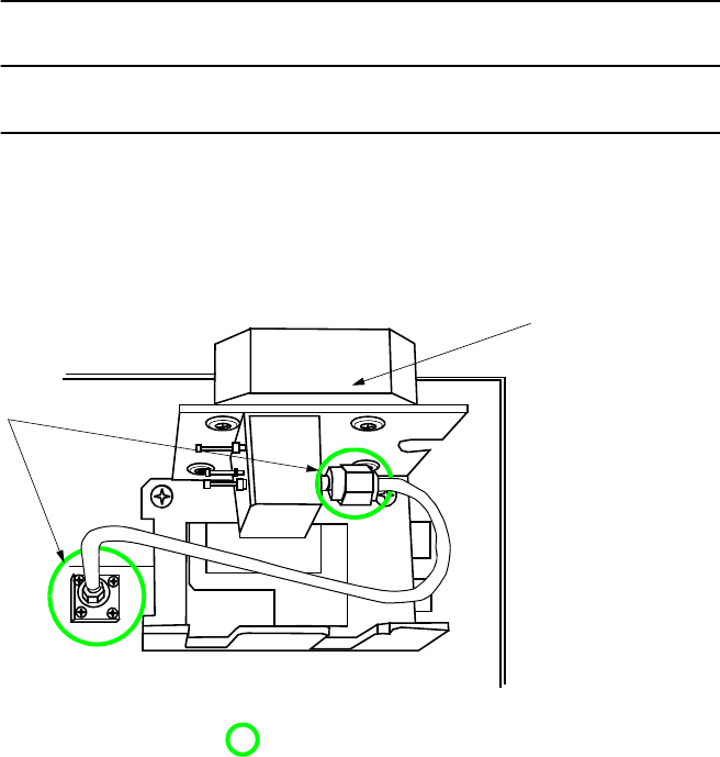
INITIAL LINE UP ROI-S07045
3-48
Chart 3-12 (Cont’d)
Step Procedure
9 Connect SJ cable between transducer and BR CKT,
10 Using torque wrench, thighten SJ cable connectors,
Tighten SJ cable
connectors.
(Down View)
When SYS2 w/o SD.
Note: Being careful, tighten alternately and
gradually either end connectors of the
SJ cable.Tightening torque: 0.6 N·m.
TRANSDUCER
: Tighten connectors, using torque wrench.
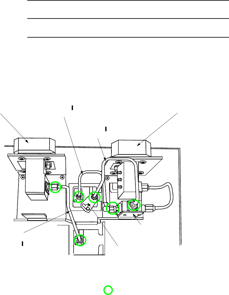
ROI-S07045 INITIAL LINE UP
3-49
Chart 3-12 (Cont’d)
Step Procedure
When the SD configuration applies to the system, connect SJ
cables shown in figure below,
When the EXP PORT applies to the system, the Duplexer and
the SJ cable connector-lock metal are provided,
(Down View)
SJ cable
connector-lock
metal.
When SYS2 e/w optional SD and EXP PORT.
TRANSDUCER FOR SD TRANSDUCER FOR MAIN
Note: Being careful, tighten alternately and gradually
either end connectors of the SJ cable.Tightening
torque: 0.6 N·m. : Tighten connectors, using torque wrench.
DUPLEXER
TRANSDUCER (RX)
BR CKT (RX)
TRANSDUCER (TX)
BR CKT (TX)
TRANSDUCER (SD)
BR CKT (SD)
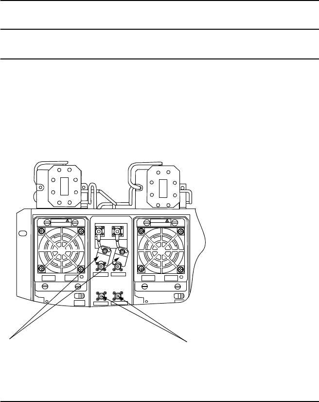
INITIAL LINE UP ROI-S07045
3-50
Chart 3-12 (Cont’d)
Step Procedure
11 Connect 50-ohm terminator to the EXP PORT on the BR CKT
which has EXP PORT, when the EXP PORT is not used,
12 Put on the SJ cable connector-lock metal when the BR CKT
which has EXP PORT is provided.
CAUTION CAUTION
TX2 EXP RX SD EXP
RX1 EXP
TX1 EXP
3.3W 3.3W ALM
ALM
DC 10V
(Rear View)
Put on the SJ cable connector-lock metal when
the BR CKT which has EXP PORT is provided. Terminate EXP PORT on the BR CKT which has
EXP PORT is provided when the EXP PORT is not
used.
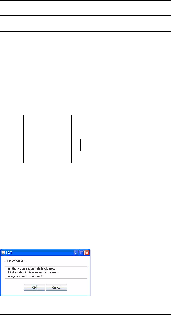
ROI-S07045 INITIAL LINE UP
3-51
Chart 3-13 PMON Clearing
Step Procedure
1 Connect the PC to the LCT port on the NLite N MDP using
USB cable, (see Fig. 3-2)
2 Enter Login name “Admin”, enter Admin password and press
the “Login” button,
3 Click the “Maintenance” button in LCT Menu,
4 Click the Maintenance2 button,
5 Then, the “PMON Clear” button is displayed in the Main Area,
6 Click the PMON Clear button,
7 Click on the “OK” button in the “WARNING” confirmation
window,
8 Disconnect the LCT from the MDP after the PMON Clearing
has been finished.
LCT MENU
Alarm/Status
Equipment Setup
Inventory
AUX I/O
Maintenance
Provisioning
Metering
PMON (History)
Maintenance1
Maintenance2
---PMON Clear---
PMON Clear
INITIAL LINE UP ROI-S07045
3-52
52 pages
(This page is intentionally left blank.)