NEC of America 58155N NLite N 5.8 GHz Digital Microwave Radio User Manual inst
NEC Corporation of America NLite N 5.8 GHz Digital Microwave Radio inst
UserManual.wiki
>
NEC of America
>
58155N User Manual
>
User Manual - Part III
Contents
1.
User Manual - Part I
2.
User Manual - Part II
3.
User Manual - Part III
4.
User Manual - Part IV
5.
User Manual - Part V
6.
User Manual - Part VI
User Manual - Part III
Navigation menu
Upload a User Manual
Namespaces
Wiki Guide
HTML
PDF
Info
Views
User Manual
Discussion / Help
Navigation


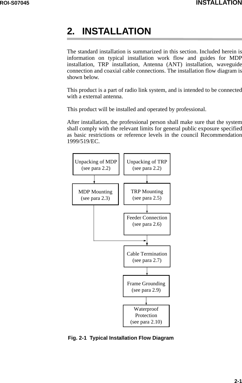
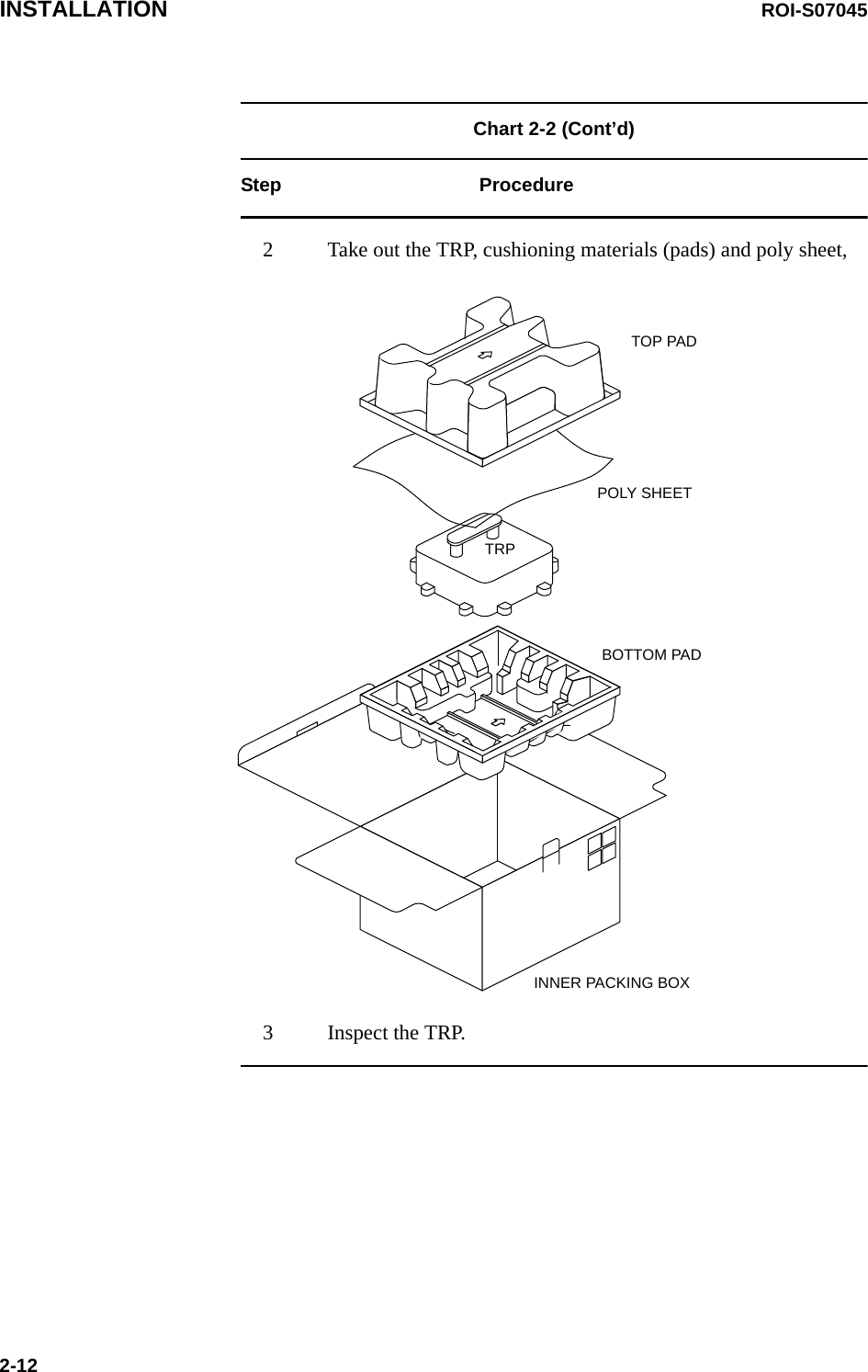
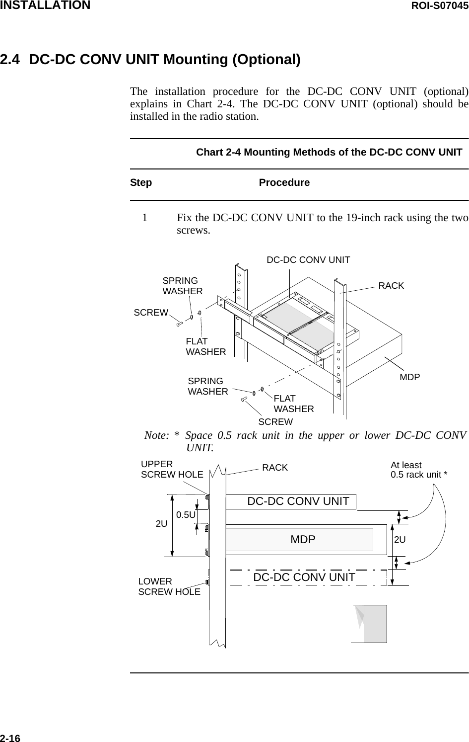
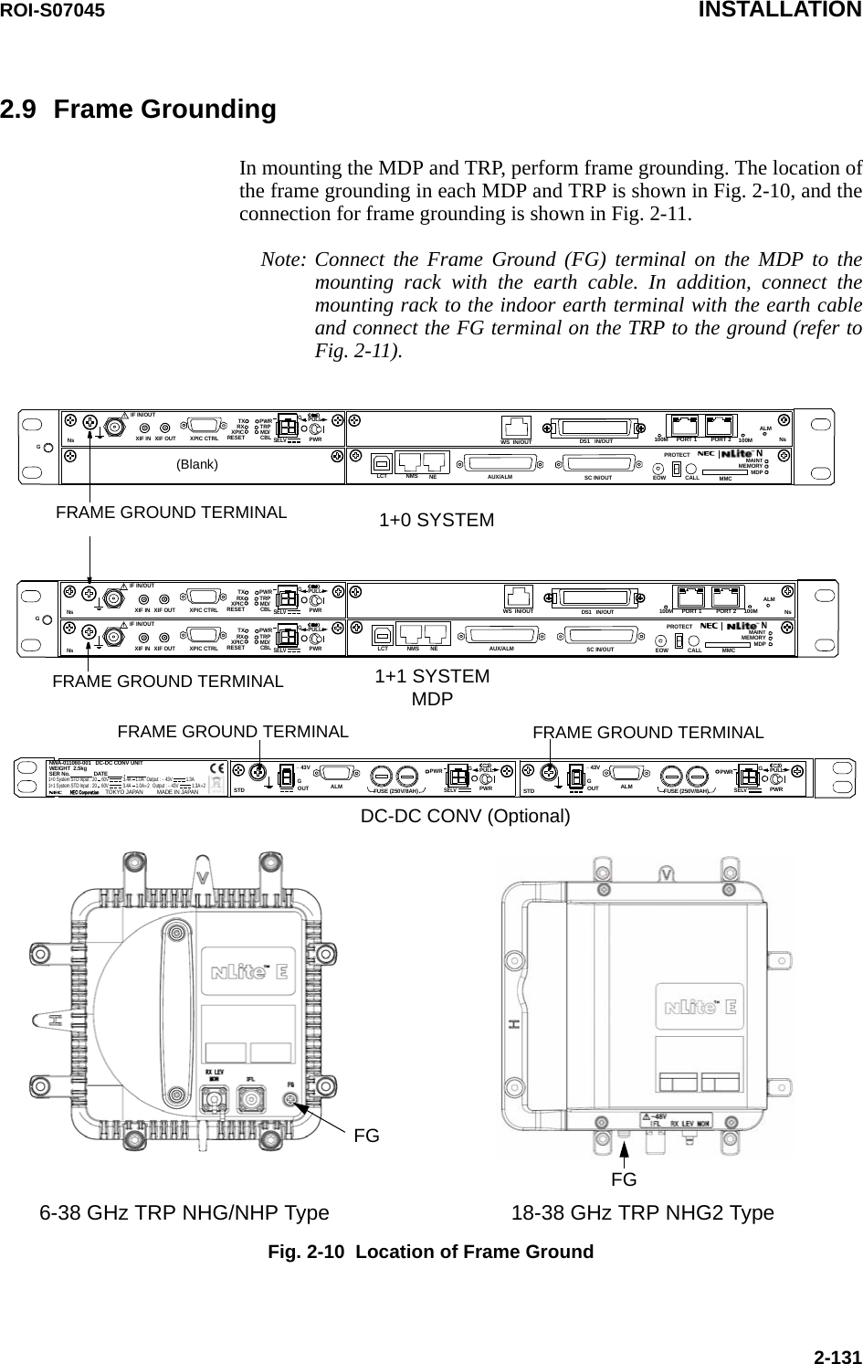
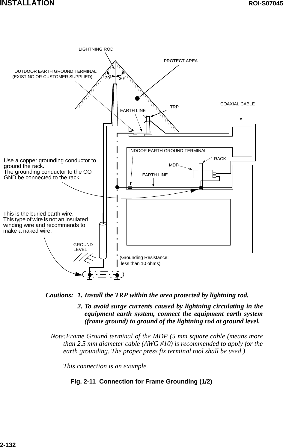
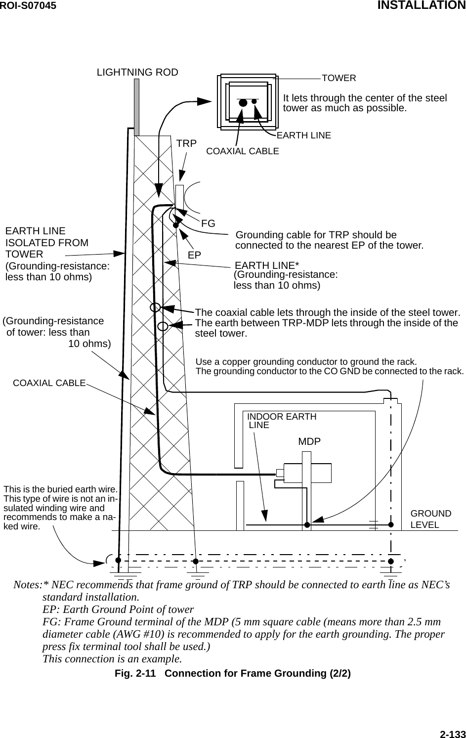
![INSTALLATION ROI-S070452-22.1 PackagesEach unpacked component of the [ ] GHz [ ] MB digital radio systemmust be checked as shown below.CONTENS LIST DRAWING NO.MDP and TRP Fig. 2-2Mounting Bracket Fig. 2-4Installation Kit Fig. 2-5 and Fig. 2-7](https://usermanual.wiki/NEC-of-America/58155N.User-Manual-Part-III/User-Guide-1263915-Page-6.png)
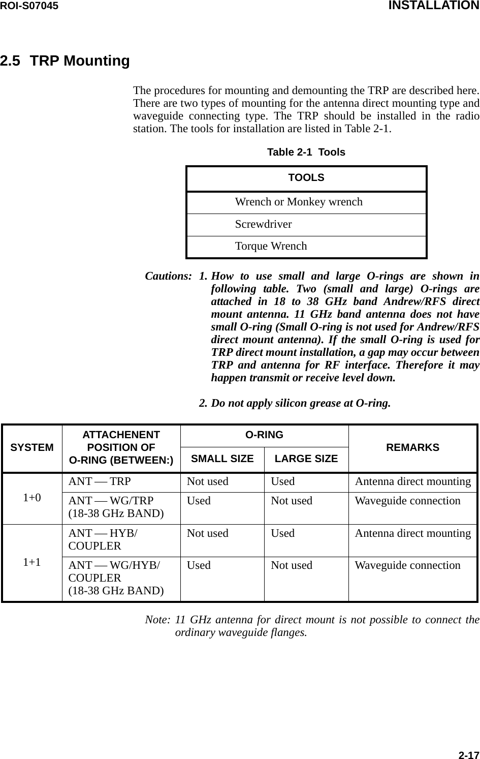
![INSTALLATION ROI-S070452-4Fig. 2-3 Contents of Optional Unit PackageΝοte:√: Usable*1: TRP (NHP type) can not be used with DC-DC CONV.*2: ALL INDOOR TRP can not be used with NWA-0011060-001 (24/48V type).SELVPWR PULLPWRALM FUSE (250V/8AH)− 43VGOUTSTDGSELVPWR PULLPWRALM FUSE (250V/8AH)− 43VGOUTSTDGNWA-011060-001 DC-DC CONV UNITSER No. DATE , WEIGHT 2.5kgMADE IN JAPANNEC Corporat ion TOKYO JAPAN1+0 System STD Input : 20 60V 3.4A 1.0A Output : − 43V 1.3A 1+1 System STD Input : 20 60V 1.3A×2 3.4A 1.0A×2 Output : − 43V 1No. DESCRIPTION1 NWA-011060-[ ] DC-DC CONV UNIT (see Fig. 2-7 for details)DC-DC CONV UNIT NHG/NHG2/EHG NHP ALL INDOOR TRPNWA-0011060-001 (24/48V type) √*1 *2NWA-011060-002 (48V type) √*1 √NWA-011060-003 (24V type) √*1 √](https://usermanual.wiki/NEC-of-America/58155N.User-Manual-Part-III/User-Guide-1263915-Page-8.png)
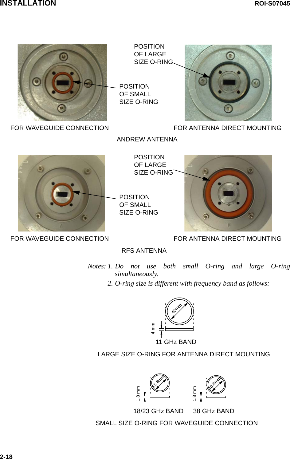
![INSTALLATION ROI-S070452-8Notes:*1 One more TRP and MODEM module are provided for HS/Twinpath configuration.*2 Two spare fuses are provided in the DC-DC CONV module.Fig. 2-7 Installation Kit Packing List of DC-DC CONV UNIT for 1+1 SystemMOLEX CONNECTOR/(FEMALE)MOLEX CONNECTOR/(FEMALE)D-SUB CONNECTOR/(FEMALE)D-SUB CONNECTOR/(FEMALE)DC-DC CONV UNIT(Optional)4513RESERVE RESERVECAUTIONHOT SURFACEAvoid contact.!2No. DESCRIPTION1 NWA-011060-[ ] DC-DC CONV UNIT2 H3040[ ] DC-DC CONV3 Power Cable (NWM-005773-001, attached to the DC-DC CONV)4Power Connector (Molex Housing M5557-4R (×1ea) and Socket Contact (5556TL (×4 each))5 Cylindrical Fuse ((CBE-006255-001) (8A) (×2 ea) *2)](https://usermanual.wiki/NEC-of-America/58155N.User-Manual-Part-III/User-Guide-1263915-Page-12.png)
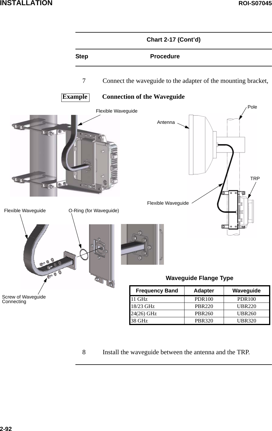
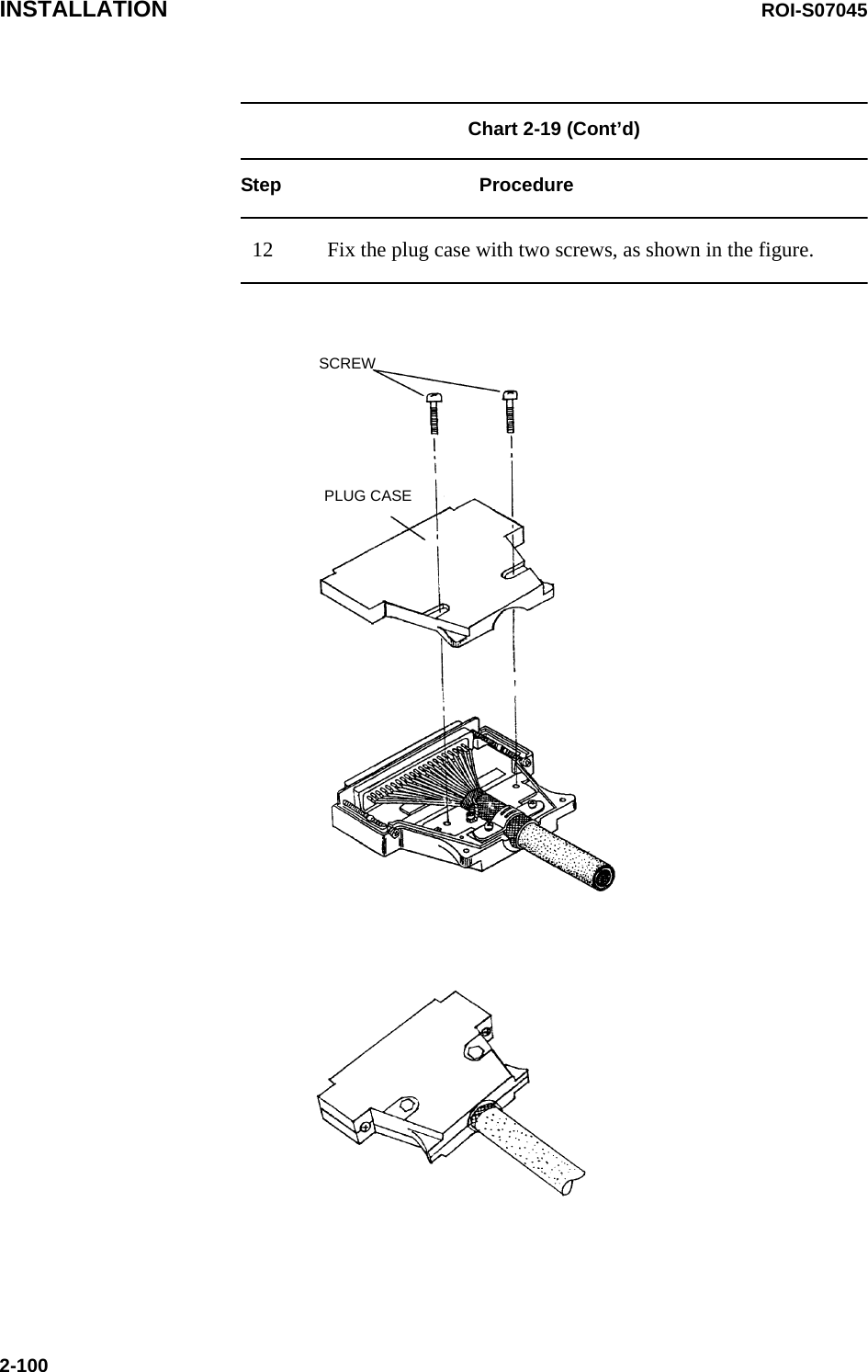
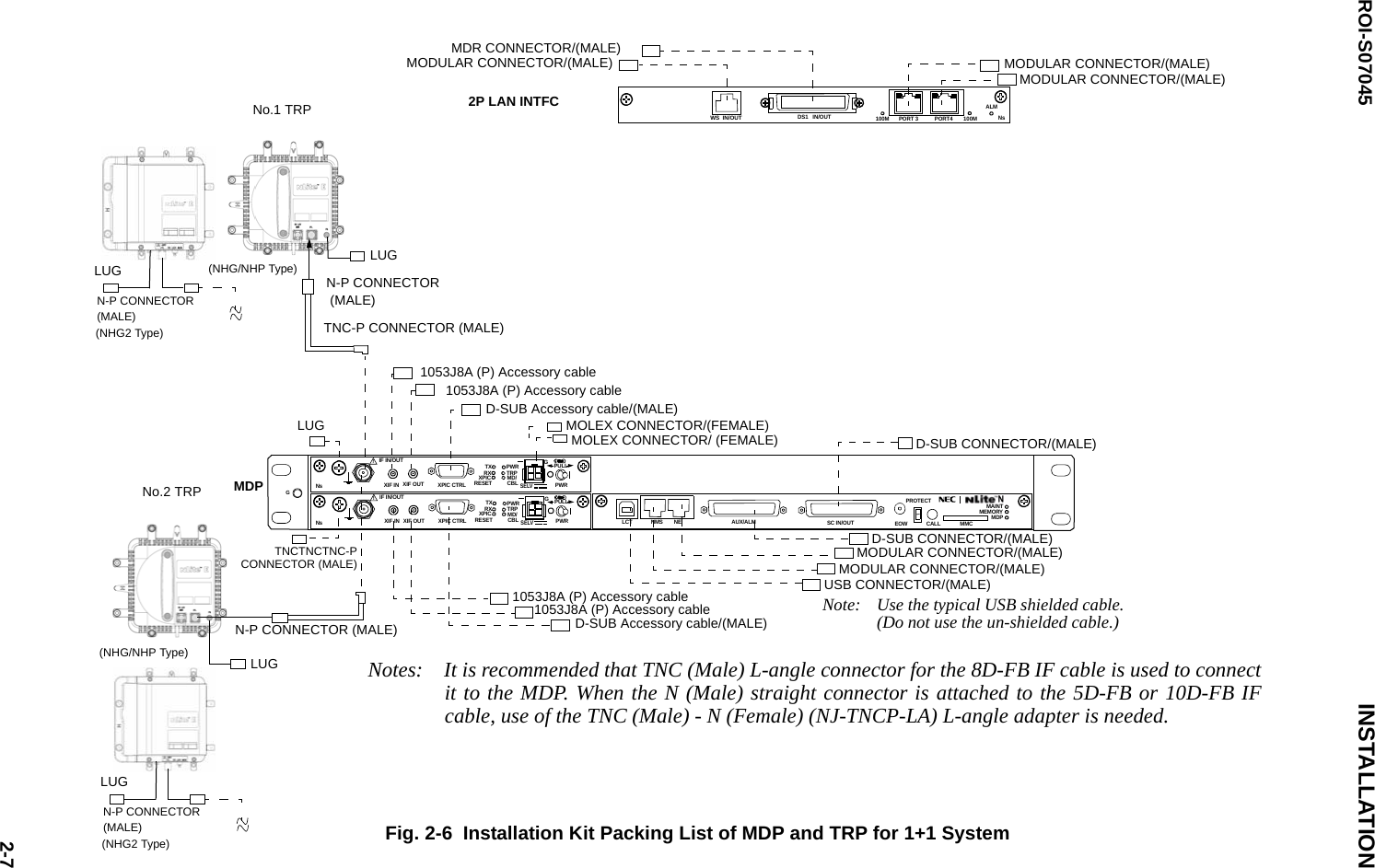
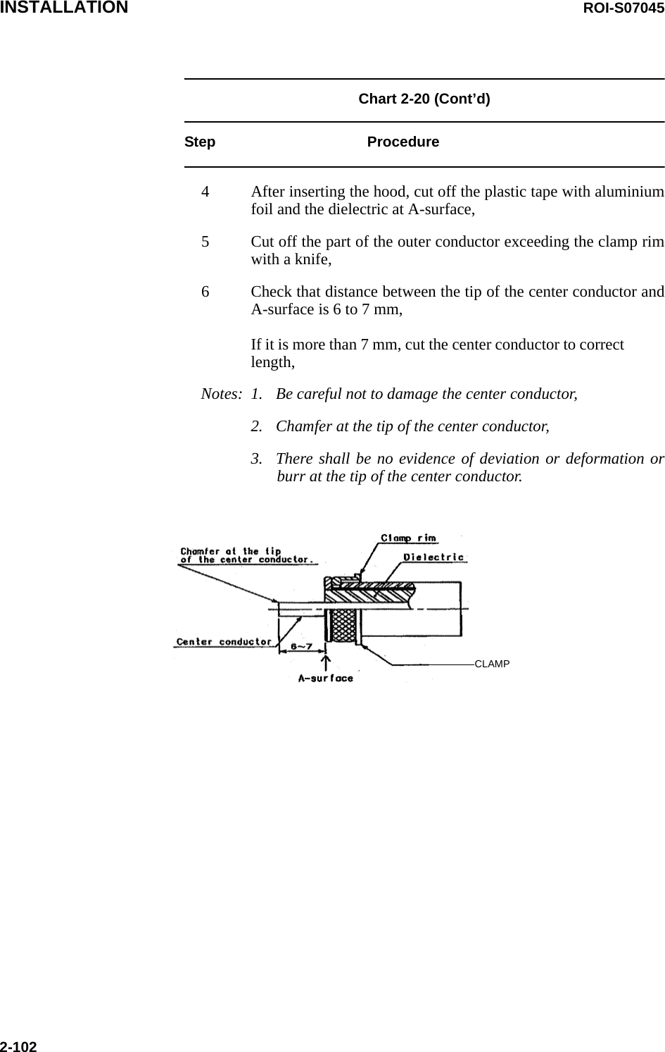
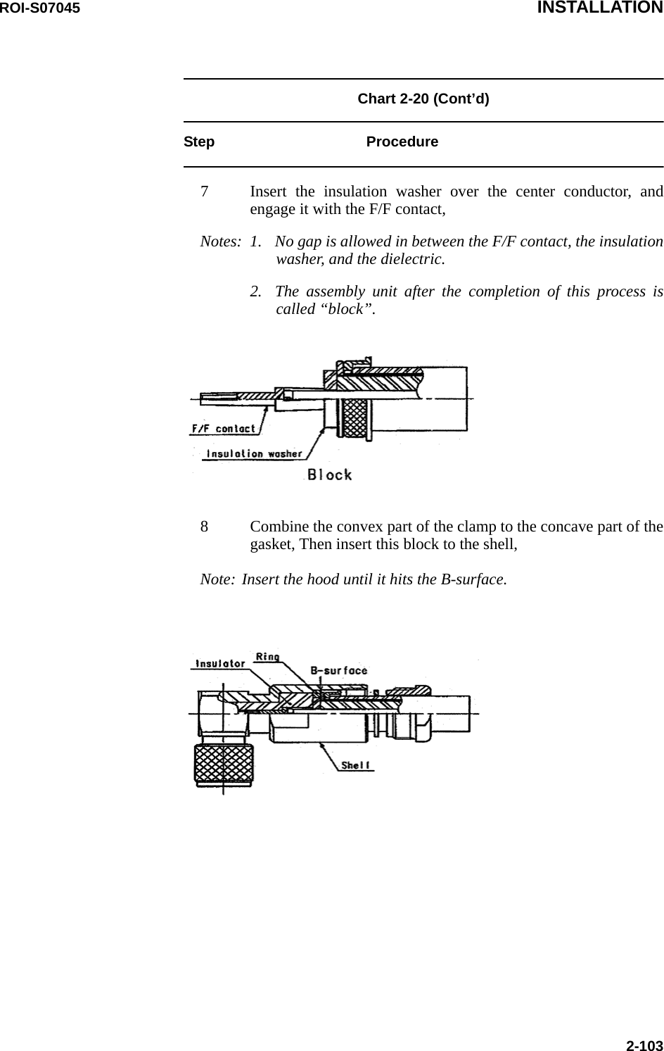
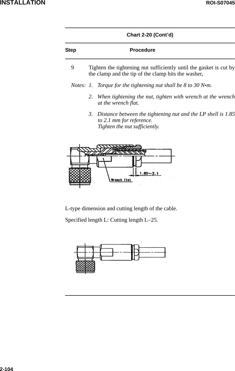
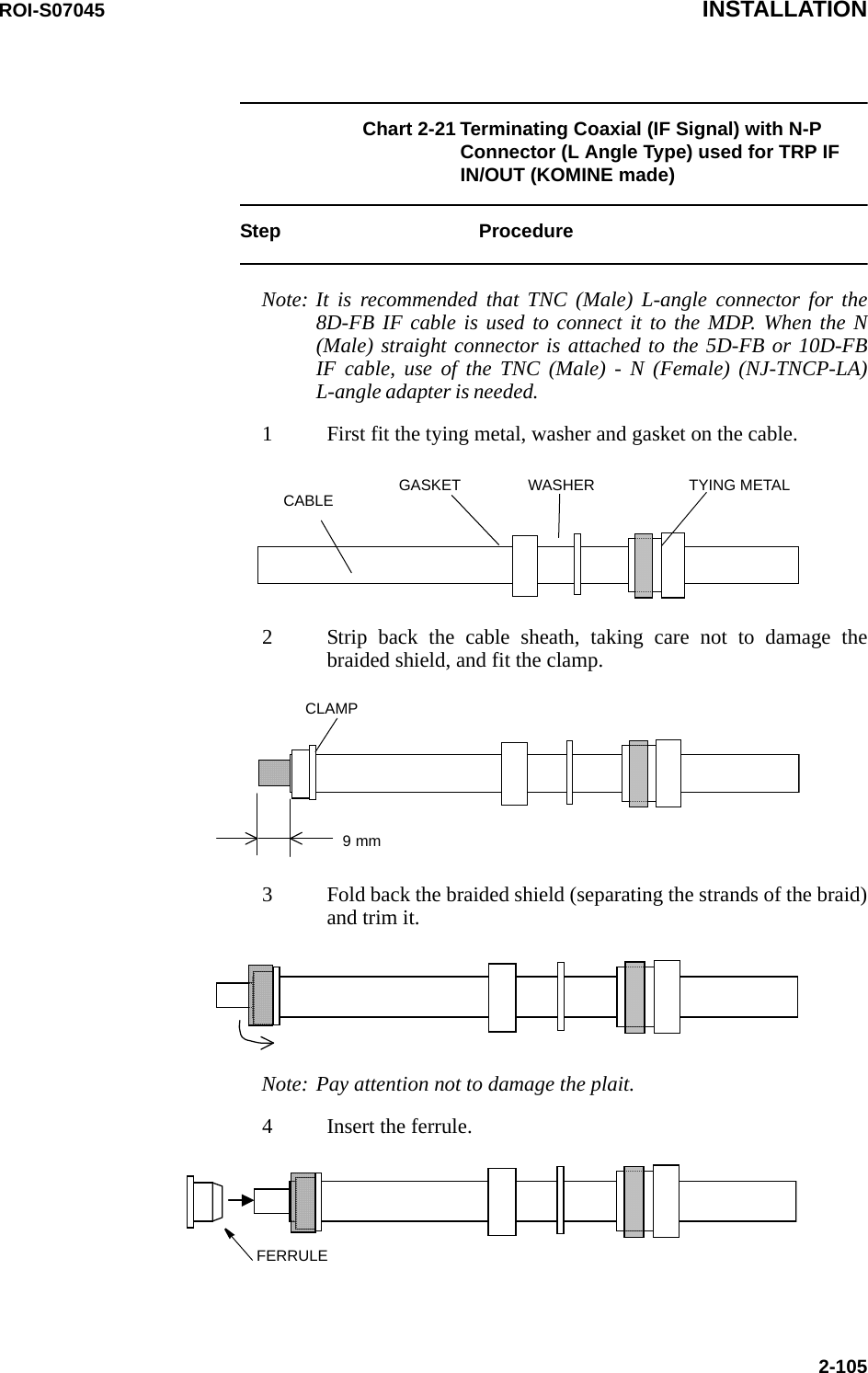
![ROI-S07045 INSTALLATION2-101Chart 2-20 Terminating IF Coaxial Cable with TNC-PConnector (L Angle Type) (HIROSE made) used for MDP IF IN/OUTStep ProcedureNote: It is recommended that TNC (Male) L-angle connector for the8D-FB IF cable is used to connect it to the MDP. When the N(Male) straight connector is attached to the 5D-FB or 10D-FBIF cable, use of the TNC (Male) - N (Female) (NJ-TNCP-LA)L-angle adapter is needed.1 Pass the tightening nut, the washer and the gasket on the cable inthe order shown in the figure.Then, strip the cable jacket in the diameter shown in the figure.[Applicable cable: 8D-FB-E]Notes: 1. Be careful of insertion direction for the gasket and thetightening nut.2. Be careful not to damage the outer conductor.3. Do not reuse the gasket because the clamp deforms it aftertightening.2 Insert the clamp to clamp the stripped cable jacket end. Open theend of the outer conductor a little,3 Insert the hood between the plastic tape with aluminium foil andthe outer conductor,Note: Use the insertion stick to open the hole of about φ9. No gap isallowed in between the clamp, the outer conductor and the hood.CLAMPHOOD](https://usermanual.wiki/NEC-of-America/58155N.User-Manual-Part-III/User-Guide-1263915-Page-105.png)
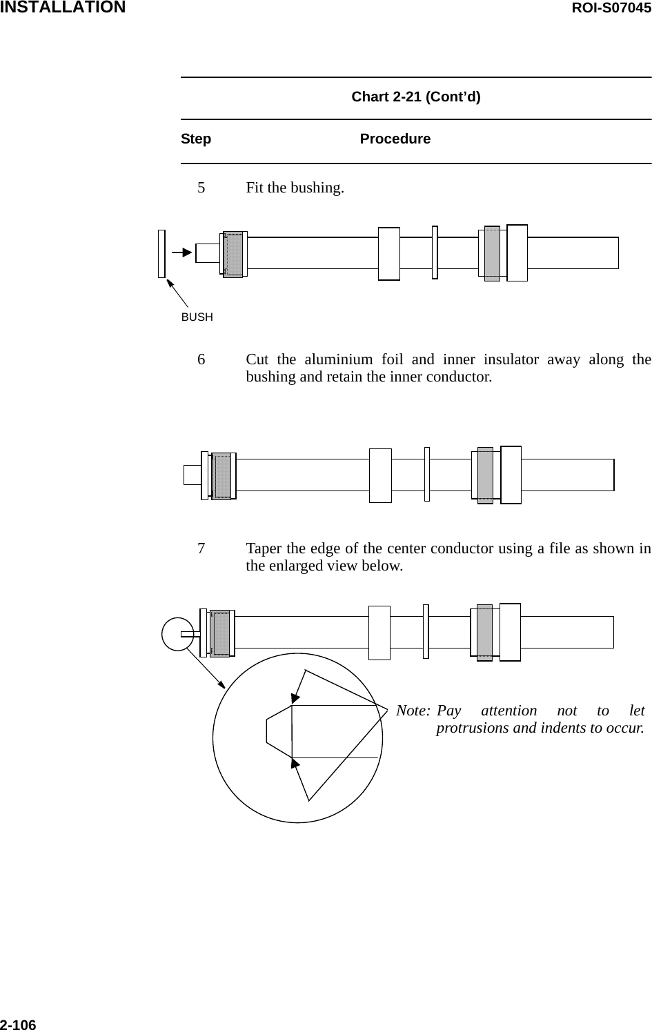
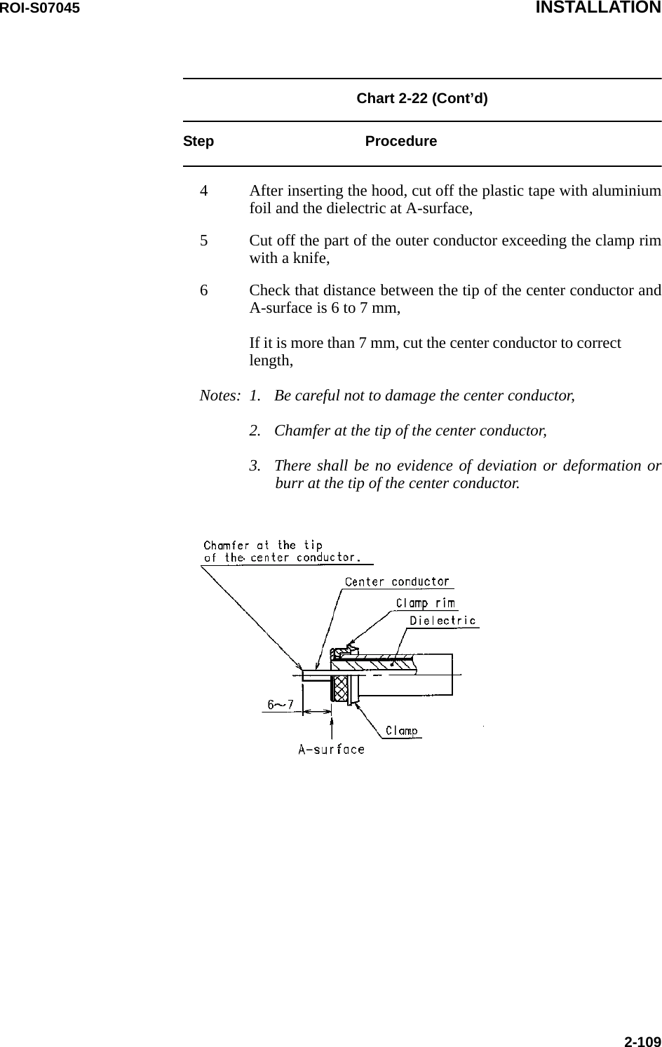
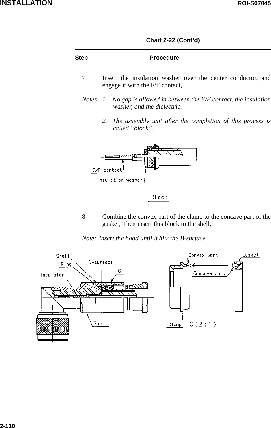
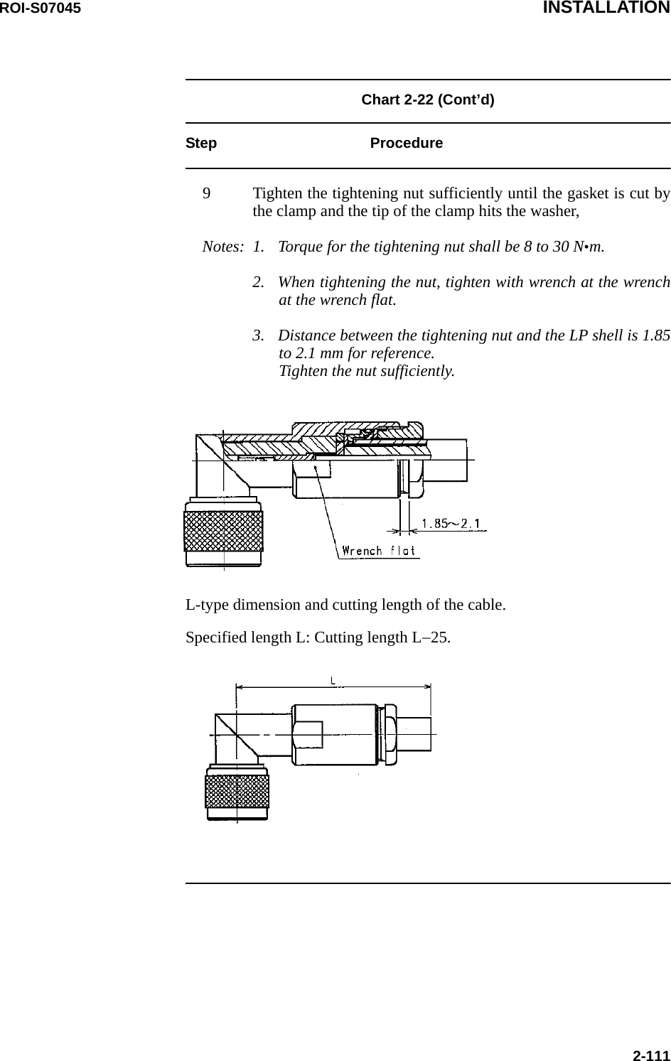
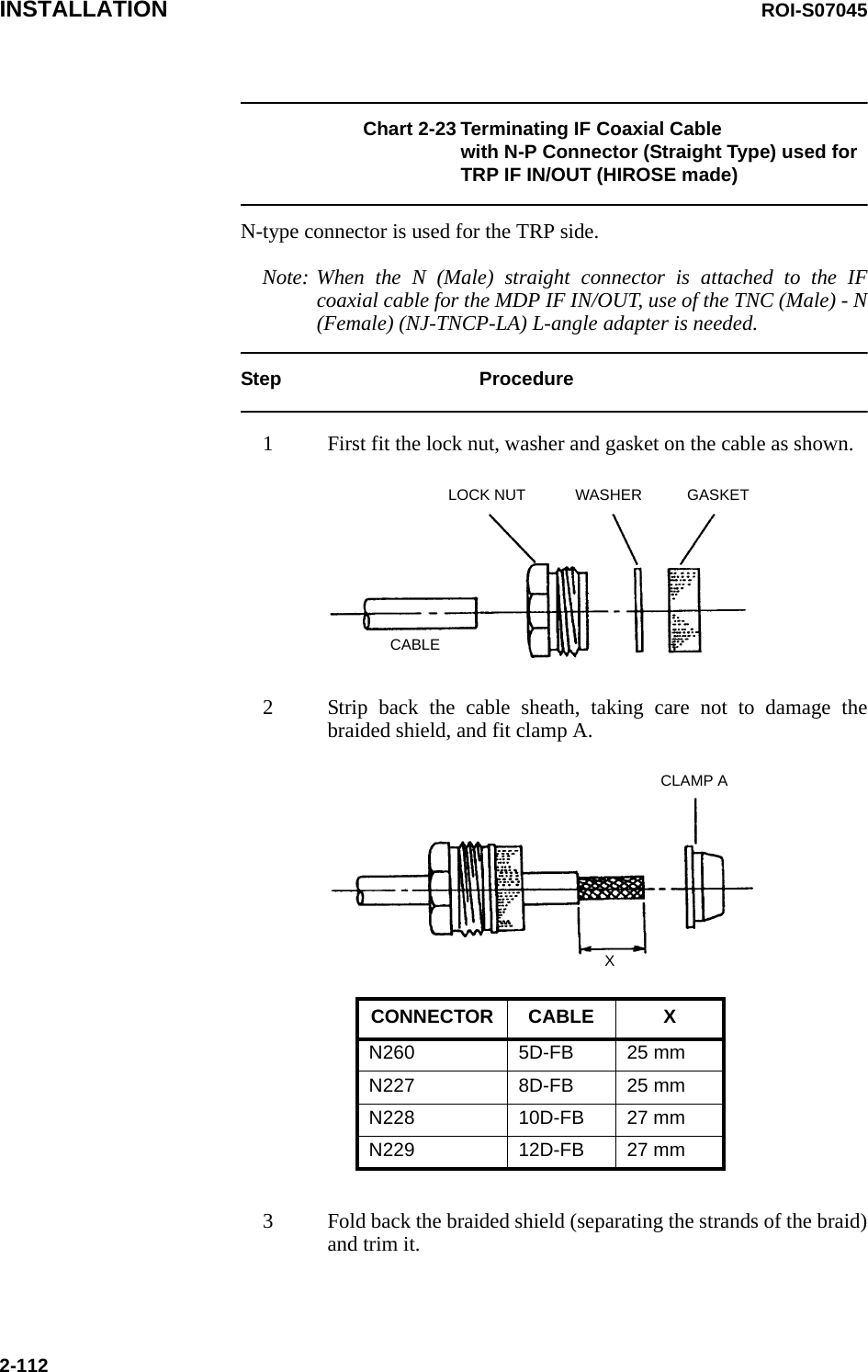
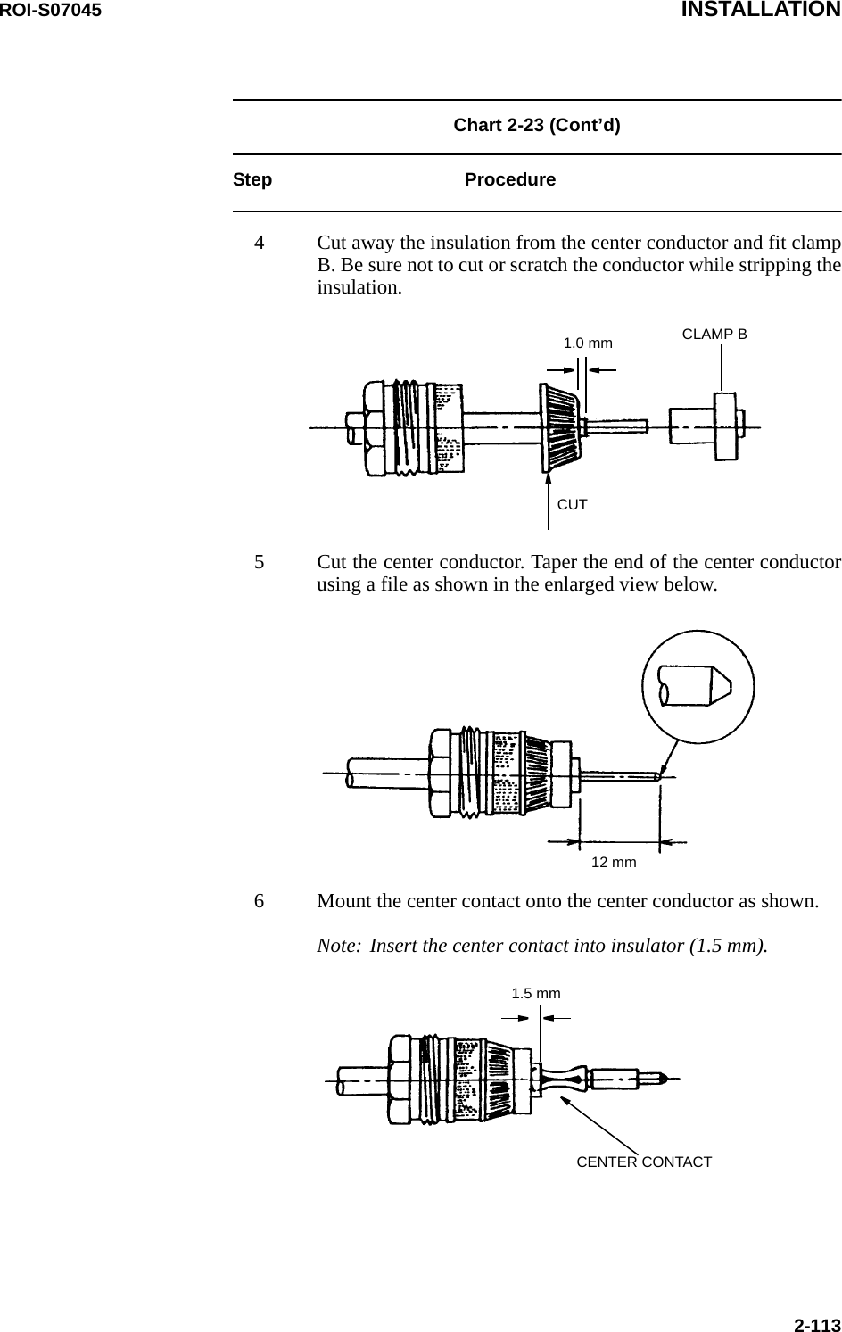
![INSTALLATION ROI-S070452-108Chart 2-22 Terminating IF Coaxial Cable with N-PConnector (L Angle Type) used for the TRP IF IN/OUT (HIROSE made)Step ProcedureNote: It is recommended that TNC (Male) L-angle connector for the8D-FB IF cable is used to connect it to the MDP. When the N(Male) straight connector is attached to the 5D-FB or 10D-FBIF cable, use of the TNC (Male) - N (Female) (NJ-TNCP-LA)L-angle adapter is needed.1 Pass the tightening nut, the washer and the gasket on the cable inthe order shown in the figure.Then, strip the cable jacket in the diameter shown in the figure.[Applicable cable: 8D-FB-E]Notes: 1. Be careful of insertion direction for the gasket and thetightening nut.2. Be careful not to damage the outer conductor.3. Do not reuse the gasket because the clamp deforms it aftertightening.2 Insert the clamp to clamp the stripped cable jacket end. Open theend of the outer conductor a little,3 Insert the hood between the plastic tape with aluminium foil andthe outer conductor,Note: Use the insertion stick to open the hole of about φ9. No gap isallowed in between the clamp, the outer conductor and the hood.](https://usermanual.wiki/NEC-of-America/58155N.User-Manual-Part-III/User-Guide-1263915-Page-112.png)
![INSTALLATION ROI-S070452-126Chart 2-28 (Cont’d) Step ProcedureStep 8. After crimping the stranded wire tothe contact using a hand tool, insertthe contact into the contact chamberwith the tool, working from thewiring side,Step 9. You can here the contacts snaphome, audible “click”,Removing crimp contactsStep 1. Position the tool from the wiringside as shown left and insert into thecontact chamber. The contact canthen easily be removed from thewiring side together with itself andreinserted in a different chamber.Step 10.Check if they are securely inplace with giving the wire agentle pull.INSERTION AND REMOVAL TOOL(09 99 000 0513)WIRECONNECTORINSERTION AND REMOVAL TOOL[REMOVAL]Contact can be removedtogether with wire.[INSERTION]Contact can be insertedtogether with wire.CONTACT CHAMBERInsertion and removal toolPosition the](https://usermanual.wiki/NEC-of-America/58155N.User-Manual-Part-III/User-Guide-1263915-Page-130.png)
![INITIAL LINE UP ROI-S070453-103.3.1 Equipment SetupIn initial lineup, the “Equipment Setup” must be performed using LCT.Chart 3-3 Equipment SetupRefer to the NLite N LCT Operation Manual in Section IV Appendix. forthe details of “3. EQUIPMENT SETUP”. • Redundancy Setting• INTFC Main (WORK) • INTFC Sub (PROT) •XPIC Usage *3• APS Function *3• Modulation Scheme• Transmission Capacity• TX RF Frequency [MHz]• RX RF Frequency [MHz] *2• Frame ID• TX Power Control•TRP Type *3• TX SW Type *3• LAN Port Usage *1• LAN Capacity1 *1• LAN Capacity2 *1• TX Start Frequency [MHz]• TX Stop Frequency [MHz]• RX Start Frequency [MHz]• RX Stop Frequency [MHz]• Frequency Step [MHz]• Shift Frequency [MHz]• Upper/Lower•Sub BandNotes:*1 For LAN transmission only.*2 There is two types TRP for the RX RF Frequency setupmode.*3 Indicate only item name, not setting anything.Type 1.When the transmitting frequency is set, the receivingfrequency is automatically assigned.Type 2.When the transmitting frequency is set, the receivingfrequency is automatically assigned and assignment of it inmanual is also available.](https://usermanual.wiki/NEC-of-America/58155N.User-Manual-Part-III/User-Guide-1263915-Page-150.png)

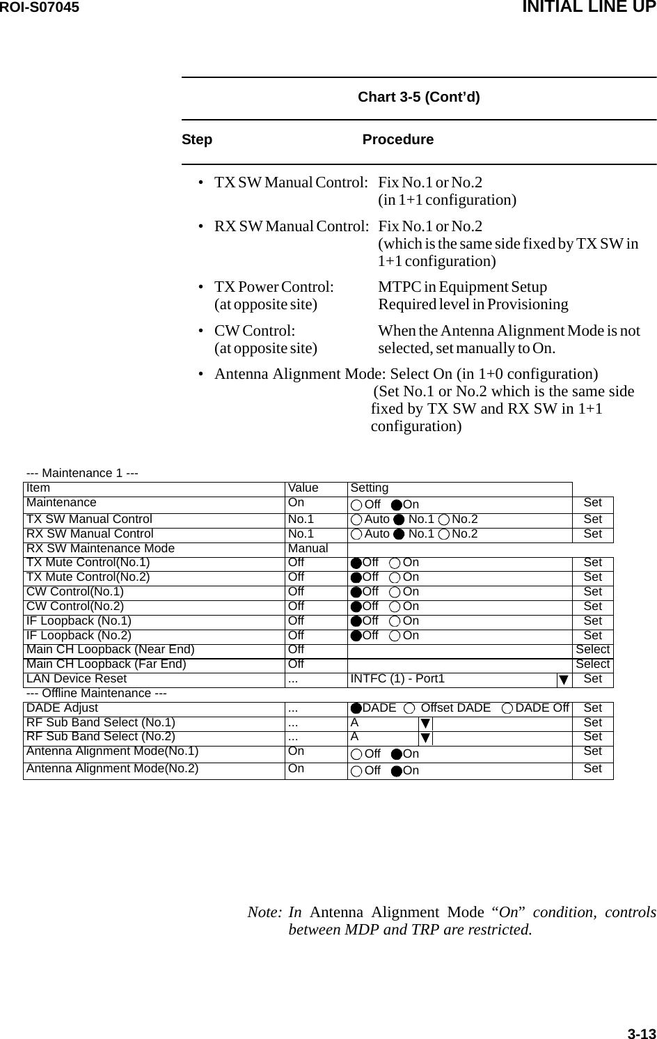
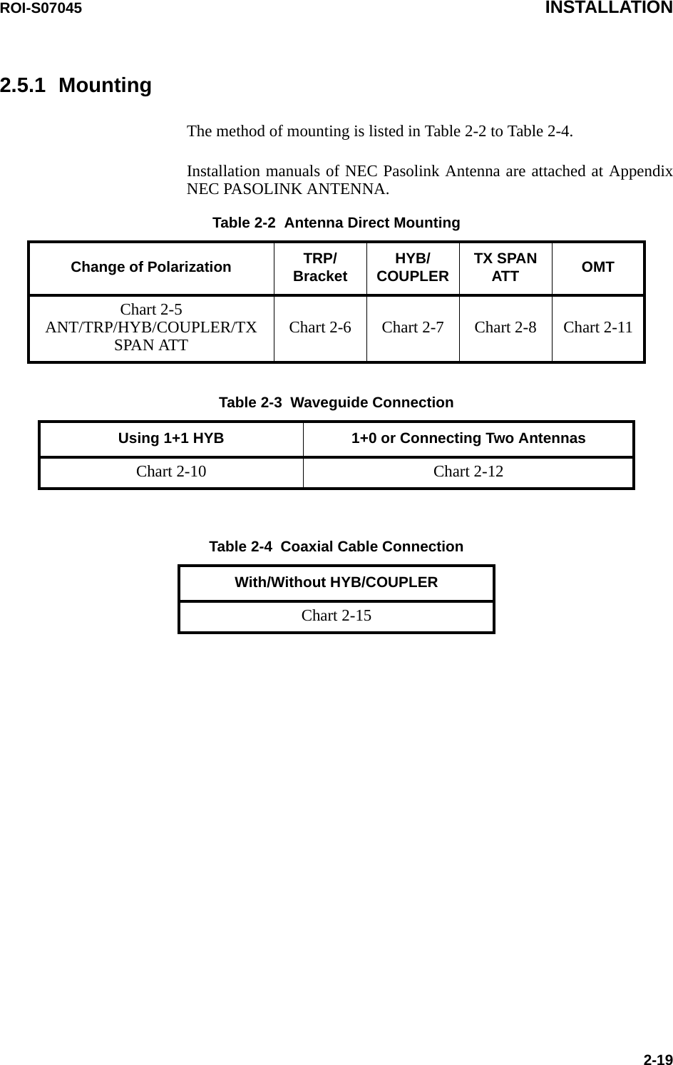
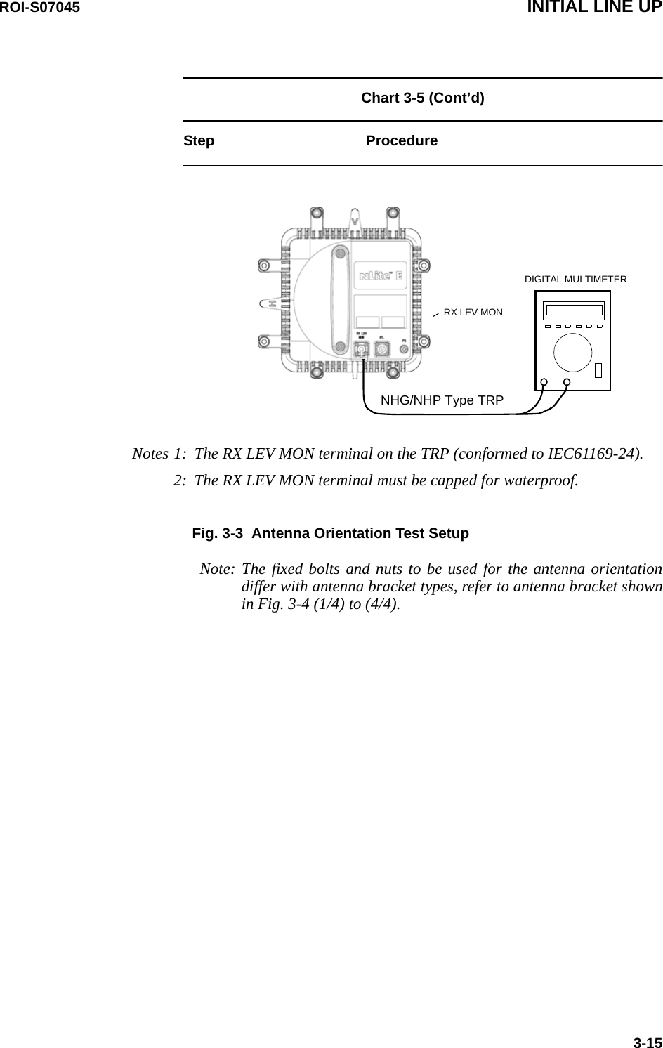
![INITIAL LINE UP ROI-S070453-14Chart 3-5 (Cont’d)Step Procedure4 At receiving station, remove a cap from the RX LEV MONjack, 5 At each station connect the digital multimeter,Note: In order to measure exact performance of AGC V, it ismandatory required to set Antenna Alignment Mode toON. The AGC voltage indication is not guaranteedoutside Antenna Alignment Mode.6 At each station, adjust the azimuth and elevation angle of theantenna alternately so that the measured voltage becomesmaximum,Note: The relation of the RX INPUT LEVEL versus RX LEVELMON(V) is shown below. RX LEVEL MON vs RX INPUT LEVEL (Typical)RX INPUT LEVEL [dBm]-80 -70 -60 -50 -40 -30 -200.5011.522.533.544.5RX LEVEL MON [V]](https://usermanual.wiki/NEC-of-America/58155N.User-Manual-Part-III/User-Guide-1263915-Page-154.png)
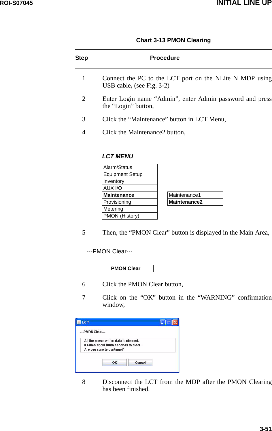
![INITIAL LINE UP ROI-S070453-30Chart 3-9 Meter ReadingStep Procedure1 Connect the PC to the LCT port on the NLite N MDP usingUSB cable, (see Fig. 3-2)2 Enter Login name “Admin”, enter Admin password and pressthe “Login” button,3 Click “Metering” button in LCT Menu, 4 Then, the values of Metering items are displayed as follows: 1+1 Configuration1+0 ConfigurationLCT MENUAlarm/StatusEquipment SetupInventoryAUX I/OMaintenanceProvisioningMeteringPMON (History)----Metering---No.1 No.2TX Power [dBm]*1 +19 +19RX Level [dBm] -49.5 -49.7Power Supply [V] *2 -45 -45BER *3 0.0E-10 Calculating----Metering---TX Power [dBm]*1 +19RX Level [dBm] -50Power Supply [V] *2 -45BER *3 1.10E-10](https://usermanual.wiki/NEC-of-America/58155N.User-Manual-Part-III/User-Guide-1263915-Page-170.png)