NEMOTO KYORINDO FAB4001 BIOMECHANICAL MOVEMENT RECORDER User Manual manual
NEMOTO KYORINDO Co., Ltd. BIOMECHANICAL MOVEMENT RECORDER manual
USERS MANUAL

Copyright Biosyn Systems Inc. April 2005
Hardware User Manual
Prepared
By
Michael Lee, William Hue, Russell McNeil
Updated: April 20, 2007
ii
Contents
1. Introduction................................................................................................................................1
1.1. List of Physical Components.......................................................................................2
2. FAB Hardware Set-Up...............................................................................................................7
2.1. Belt Clip Set-Up ..........................................................................................................7
2.2. Date and Time Setup ...................................................................................................7
2.3. Sensor Set-Up..............................................................................................................8
2.3.1. 3D Sensors....................................................................................................8
2.3.2. Foot Sensors .................................................................................................8
3. Belt Clip Modes..........................................................................................................................9
3.1. Data Recording Mode..................................................................................................9
3.1.1. View Battery Voltage ...................................................................................9
3.1.2. Recording Data.............................................................................................9
3.1.2.1. Data Collection Error Handling..........................................13
3.1.2.1.1. Momentary Radio Drop-out Error.................13
3.1.2.1.2. Sensor Failure Error........................................13
3.1.2.1.3. Slow Memory Card Error...............................14
3.1.2.1.4. Low Battery Voltage Warning........................14
3.1.2.2. Attaching Sensors to the Body.............................................15
3.1.2.2.1. Sensor Orientation ...........................................15
3.1.2.2.2. Sensor Locations...............................................15
3.1.3. Setting the Date and Time ..........................................................................16
3.2. Clinician Mode..........................................................................................................16
3.2.1. Setting up the Sensor List...........................................................................16
3.2.2. Recording Data...........................................................................................17
1. Introduction
The FAB System aids in assessment of human biomechanical movement. It consists of a number of
electronic sensors and a data-collection (“Belt Clip”) unit to be worn or located near the subject
being evaluated.
This document describes how to set-up and use the FAB data collection device with sensors.
Model: FAB4001
IC (Industry Canada): 6461A-FAB4001
FCC ID: T6DFAB4001
“This device has been tested and complies with the regulations of Industry Canada Technical
Standard RSS-210.”
NOTE:
“This equipment has been tested and found to comply with the limits for a Class A digital device,
pursuant to Part 15 of the FCC rules. These limits are designed to provide reasonable protection
against harmful interference when the equipment is operated in a commercial environment. This
equipment generates, uses, and can radiate radio frequency energy and, if not installed and used in
accordance with the instruction manual, may cause harmful interference to radio communications.
Operation of this equipment in a residential area is likely to cause harmful interference in which
case the user will be required to correct the interference at their own expense.
Operation is subject to the following two conditions: (1) this device may not cause harmful
interference and (2) this device must accept and harmful interference received, including
interference that may cause undesired operation.”
Caution!
Changes or modifications to this equipment, not expressly approved by the manufacturer could void
the user’s authority to operate the equipment.
NOTE: THE MANUFACTURER IS NOT RESPONSIBLE FOR ANY RADIO OR TV
INTERFERENCE CAUSED BY UNAUTHORIZED MODIFICATIONS TO THIS EQUIPMENT.
SUCH MODIFICATIONS COULD VOID THE USER'S AUTHORITY TO OPERATE THE
EQUIPMENT.

2
1.1. List of Physical Components
The FAB Phase 1 System consists of the following items:
1. Left Arm Sensor (ID 1)
2. Right Arm Sensor (ID 2)
3. Upper Back Sensor (ID 3)
4. Lower Back Sensor (ID 4)
5. Left Leg Sensor (ID 5)
6. Right Leg Sensor (ID 6)
7. Left Wrist (ID 7)
8. Right Wrist (ID 8)
9. Left Calf (ID 9)
10. Right Calf (ID 10)
11. Left Foot (ID 128)
12. Right Foot (ID 129)
13. Left and Right Foot Transducers (black insoles)
14. Belt Clip with Batteries
15. Memory Card
16. Memory Card Reader with Software CD and USB Cable
17. FAB Software CD
18. This Manual
Limited Warranty and Technical Support
United States and Canada
This document includes warranty information for Biosyn Systems’ FAB Hardware products in
Canada and the United States.
Product Warranty Periods
Product Duration of Warranty period
Sensor hardware 3 years
Foot transducers 1 year - excluding natural wear and tear
Included hardware battery charger and batteries 1 year
Included straps Not warranted
Biosyn Systems Inc. (for U.S. and Canadian Sales) (Biosyn) warrants this product against defects in
material or workmanship for the time periods and as set forth above. Pursuant to this Limited
Warranty, Biosyn will, at its option, (i) repair the product using new or refurbished parts or (ii)
replace the product with a new or refurbished product. For purposes of this Limited Warranty,
“refurbished” means a product or part that has been returned to its original specifications. In the
event of a defect, these are your exclusive remedies.
3
This Limited Warranty covers only the hardware components packaged with the Product. It does
not cover technical assistance for hardware or software usage and it does not cover any software
products whether or not contained in the Product; any such software is provided “AS IS” unless
expressly provided for in any enclosed software Limited Warranty. Please refer to the End User
License Agreements included with the Product for your rights and obligations with respect to the
software.
This warranty does not apply to expendable parts. This limited warranty does not extend to any
products from which the serial number has been removed or that has been damaged or rendered
defective (a) as a result of misuse, abuse, or other external causes; (b) by operation outside the
usage parameters stated in the user documentation; (c) by the use of parts not manufactured or sold
by Biosyn Systems; or (d) by modifications or service by anyone other than (i) Biosyn Systems, (ii)
a Biosyn authorized service provider, or (iii) your own installation of end-user replaceable Biosyn
or Biosyn approved parts, if available for your product in the servicing country.
With all batteries, the maximum capacity of the batteries will decrease with time or use. The battery
warranty does not cover changes in battery capacity. Your batteries are only warranted from defects
in materials or workmanship resulting in failure. To determine whether you batteries has had a
warranted failure, you may be required to send your system back to Biosyn Systems.
Battery life is not warranted and will vary depending on product configuration and usage, including
but not limited to product model, applications running, power management settings, and product
features.
Limitation of Liability
This Limited Warranty only covers product issues caused by defects in the material or workmanship
during ordinary consumer use; it does not cover product issues caused by any other reason,
including but not limited to acts of God, misuse, limitations of technology, or modifications of or to
any part of the Biosyn Product. This Limited Warranty does not cover Biosyn Products sold AS IS
or WITH ALL FAULTS or consumables (such as batteries, fuses, straps, and foot sensors).
If your FAB brand hardware product fails to work as warranted above, your sole and exclusive
remedy shall be repair or replacement. Biosyn’s maximum liability under this warranty is expressly
limited to the lesser of the price you have paid for the product or the cost of repair or replacement of
any hardware components that malfunction in conditions of normal use.
Limitation on Damages
Biosyn is not liable for any damages caused by the product or the failure of the product to perform,
including any lost profits or savings or special, incidental, or consequential damages. Biosyn is not
liable for any claim made by a third party or made by you for a third party.
This limitation of liability applies whether damages are sought, or a claim made, under this
warranty or as a tort claim (including negligence and strict product liability), a contract claim, or
4
any other claim. This limitation of liability cannot be waived or amended by any person. This
limitation of liability will be effective even if you have advised Biosyn or an authorized
representative of Biosyn of the possibility of any such damages. This limitation of liability,
however, will not apply to claims for personal injury.
This warranty gives you specific legal rights. You may also have other rights that may vary from
state to state, province to province, or from country to country. You are advised to consult
applicable state, province, or country laws for a full determination of your rights.
Options and Software
The warranty terms and conditions for Biosyn options are as indicated in the Warranty applicable to
Biosyn Options. BIOSYN DOES NOT WARRANTY SOFTWARE PRODUCTS, INCLUDING
AND SOFTWARE PRODUCTS OR THE OPERATING SYSTEM. Biosyn’s only obligations with
respect to software distributed by Biosyn under the Biosyn brand name are set forth in the
applicable end-user license or program license agreement. Non-Biosyn manufactures, suppliers, or
publishers may provide their own warranties directly to you.
Hardware Technical Support
Free hardware technical support is provided for the duration of your 3 year warranty. Once the
warranty has expired, hardware support is available for an additional fee.
Repair/Replacement Warranty:
This Limited Warranty shall apply to any repair, replacement part or replacement product for the
remainder of the original Limited Warranty period or for ninety (90) days, whichever is longer. Any
parts or product replacement under this Limited Warranty will become the property of Biosyn.
Software Technical Support
Software technical support is defined as assistance with questions and issues about the software that
was either preinstalled by Biosyn Systems on the Biosyn branded product or that was included with
the Biosyn branded product at the time of your purchase or lease of the product. Technical support
for the software is available for the first thirty (30) days from date of the product purchase or lease.
Your dated sales or delivery receipt, showing the date of purchase or lease of the product, is your
proof of the purchase or lease date. You may be required to provide proof of purchase or lease as a
condition of the receiving software technical support. After the first thirty (30) days, technical
support for the software that was either preinstalled by Biosyn Systems on the Biosyn branded
product or that was included with the Biosyn branded product at the time of your purchase or lease
of the product is available for a fee. The software technical support period will be extended to a
total of ninety (90) days just for registering you product. Register your product at
http://www.biosyn.ca/support
5
After the free software support period, software technical support will be available for a fee. In
addition, Biosyn offers a one-year software technical support extension for $59.95 - U.S. (subject to
change without notice) or $64.99 – Canada, which provides telephone technical support for all
installed software that came with your FAB System. To order a one-year software technical support
extension, please contact Biosyn Systems.
Use Equipment Safely
! WARNING: To reduce the risk of electronic shock or damage to your equipment:
• Plug the power cord of the charger into an AC outlet that is easily accessible at all times
• Disconnect power from the sensors by unplugging the power cord from the AC outlet (not
by unplugging the adapter from the sensors first)
• If provided with a 3-pin attachment plug on the power cord of your charger, plug the cord
into a grounded (earthed) 3-pin outlet. Do not disable the power cord grounding pin; for
example, by attaching a 2 pin adapter. The grounding pin is an important safety feature.
• DO NOT ATTEMPT TO CHARGE THE SENSORS WHILE THEY ARE BEING
WORN. There is a safety circuit which will prevent sensor usage while charging. However,
attaching a power source to an individual while the sensors are worn could result in shock,
burns, or damage to the equipment.
• TO PREVENT FIRE OR SHOCK HAZARD, DO NOT EXPOSE YOUR SENSORS
TO RAIN OR MOISTURE.
• To avoid shock do not open any sensor.
• The sensors are designed to operate only with Batteries provided by Biosyn Systems Inc.
! WARNING
• DO NOT submerse the sensors in water to clean. Use a disinfecting wipe to lightly
clean the plastic case.
• Use a disinfecting wipe to lightly clean the foot transducers.
6
Model: FAB4001
IC (Industry Canada): 6461A-FAB4001
FCC ID: T6DFAB4001
“This device has been tested and complies with the regulations of Industry Canada Technical
Standard RSS-210.”
NOTE:
“This equipment has been tested and found to comply with the limits for a Class A digital device,
pursuant to Part 15 of the FCC rules. These limits are designed to provide reasonable protection
against harmful interference when the equipment is operated in a commercial environment. This
equipment generates, uses, and can radiate radio frequency energy and, if not installed and used in
accordance with the instruction manual, may cause harmful interference to radio communications.
Operation of this equipment in a residential area is likely to cause harmful interference in which
case the user will be required to correct the interference at their own expense.
Operation is subject to the following two conditions: (1) this device may not cause harmful
interference and (2) this device must accept and harmful interference received, including
interference that may cause undesired operation.”
Caution!
Changes or modifications to this equipment, not expressly approved by the manufacturer could void
the user’s authority to operate the equipment.
NOTE: THE MANUFACTURER IS NOT RESPONSIBLE FOR ANY RADIO OR TV
INTERFERENCE CAUSED BY UNAUTHORIZED MODIFICATIONS TO THIS EQUIPMENT.
SUCH MODIFICATIONS COULD VOID THE USER'S AUTHORITY TO OPERATE THE
EQUIPMENT.
Some states or jurisdictions do not allow the exclusion or limitation of incidents or
consequential damages, or allow limitations on how long an implied warranty lasts, so the
above limitations or exclusions may not apply to you. This Limited Warranty gives you
specific legal rights and you may have other rights which vary from state to state or
jurisdiction to jurisdiction.
7
2. FAB Hardware Set-Up
The FAB system consists of a hand held data collection device (Belt Clip), ten 3D sensors and two
Foot sensors. Minimal set-up is required before the system can be used properly.
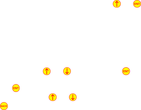
2.1. Belt Clip Set-Up
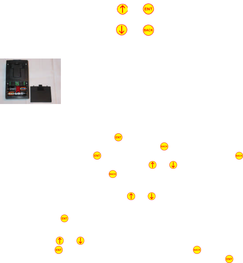
The FAB Belt Clip has four push-buttons and requires two alkaline ‘AA’ batteries for power.
Figure 1: Belt Clip Button Configuration
Install the batteries by sliding open the battery compartment door and
loading the batteries, taking care to observe correct orientation. When you
insert the batteries you will hear a beep, which tells you the Belt Clip is
ready for operation. Replace the battery door. Before the Belt Clip may be
used to record data, the current date and time must be set.
2.2. Date and Time Setup
1. To set the time, press and hold the button if the Belt Clip display is blank. If the display
is not blank, turn OFF the Belt Clip by pressing the button repeatedly until the screen
goes blank. In general the button is used to select or confirm an entry. The is used to
reach a previous screen or stop recording. The and buttons are used to scroll through
the various menus. Pressing the button while at the main menu will shut the Belt Clip
OFF.
2. After turning the Belt Clip ON, use the and buttons to reach the “Set date and Time”
screen.
3. Next press the button. This will bring you to another screen which will allow you to set
the date and time.
4. By using the and buttons you can change appropriate fields on the date and time
screen. The button will move the cursor to the right and the button will move the
cursor to the left. To save the date and time, exit the screen by pressing the button until
you return to the main menu.

8
When the date and time is properly set, the FAB system is ready to use. To turn OFF the Belt Clip,
press the button until the LCD screen becomes blank and a double beep is heard.
2.3. Sensor Set-Up
There are 2 types of sensor in the FAB system: 3-D Sensors (IDs 1 through 10) and Foot Sensors
(ID 128 and 129).
2.3.1. 3D Sensors
The 3D sensors are very easy to set up. For battery management the 3D sensors automatically turn
themselves OFF after 2 minutes of turning the Belt Clip OFF.
NOTE: You may have to wait up to 30s seconds for the sensors to turn back ON after they have
shutdown. For example, if you wish to use the 3D sensors after they have not been in use for 2
minutes, a “wake up” signal from the Belt Clip is required. This signal could be any Belt Clip
function such as checking Battery Voltage or Recording Data.
2.3.2. Foot Sensors
The Foot sensors are also very easy to set up. Simply removing the power plug and inserting the
foot transducer plug will turn the sensor ON. For battery management the Foot Sensors
automatically turn themselves OFF after 2 minutes of turning the Belt Clip OFF or removing the
foot transducer.
NOTE: You may have to wait up to 30s seconds for the sensors to turn back ON after they have
shutdown. For example, if you wish to use the Foot sensors after they have not been in use for 2
minutes, a “wake up” signal from the Belt Clip is required. This signal could be any Belt Clip
function such as checking Battery Voltage or Recording Data.

9
3. Belt Clip Modes
The FAB Belt Clip unit has 2 different modes of operation: Data Recording Mode and Clinician
Mode.
NOTE: we recommend that while in the clinic, use clinician mode as the calibration time is slightly
faster, but both modes record exactly the same data.
3.1. Data Recording Mode
To enter “Data Recording Mode” press and hold the button if the display is blank. The first
screen you will see displays the Belt Clip firmware build date. Next, the Belt Clip will display
“Data Recording Mode” to confirm your request. “Data Recording Mode” has 3 main functions:
View Battery Voltage, Record Data and Set Date and Time.
NOTE: In general, the button is used to select or confirm an entry. The is used to reach a
previous screen or stop recording. The and buttons are used to scroll through the various
menus.
3.1.1. View Battery Voltage
Navigate to the “Battery Cond.” (battery condition) screen by using the and buttons. If you
are not already at the main menu, use the button to reach the main menu.
At the “Battery Cond.” screen press the button. You may then use the and buttons to
view the battery voltages for the different sensors (if the sensors are awake). If the display shows
“offline” you may have to wait up to 30s before the display shows the sensor battery voltage--if the
display showed offline the sensor was in sleep mode, when the display shows a battery voltage the
sensor is now awake and ready for data collection. If the display does not show sensor battery
voltage after 30s please ensure the power plug is removed from the sensor and the foot transducer
plug is inserted if you are using a foot sensor. When you are finished viewing battery voltage, press
the button to return to the main menu.
NOTE: A fully charged sensor battery has a voltage of approximately 4.1V. A low battery
condition exists when the battery voltage is less than 3.65V. At 3.6V you have approximately 45
minutes of sensor use until the battery voltage gets to low.
The Belt Clip batteries are just over 3.0V when fresh, and should be replaced when they get down
to 2.0V. To ensure there is enough battery life for your tests, charge the sensors fully and change
the Belt Clip batteries regularly.
3.1.2. Recording Data
Carefully insert the SD memory card into the slot when the Belt Clip display is blank. When
viewing the Belt Clip from the TOP, (TOP being the side with the buttons) ensure the card label is
facing up and the contacts (on the back of the card) should enter the Belt Clip first. Do not force
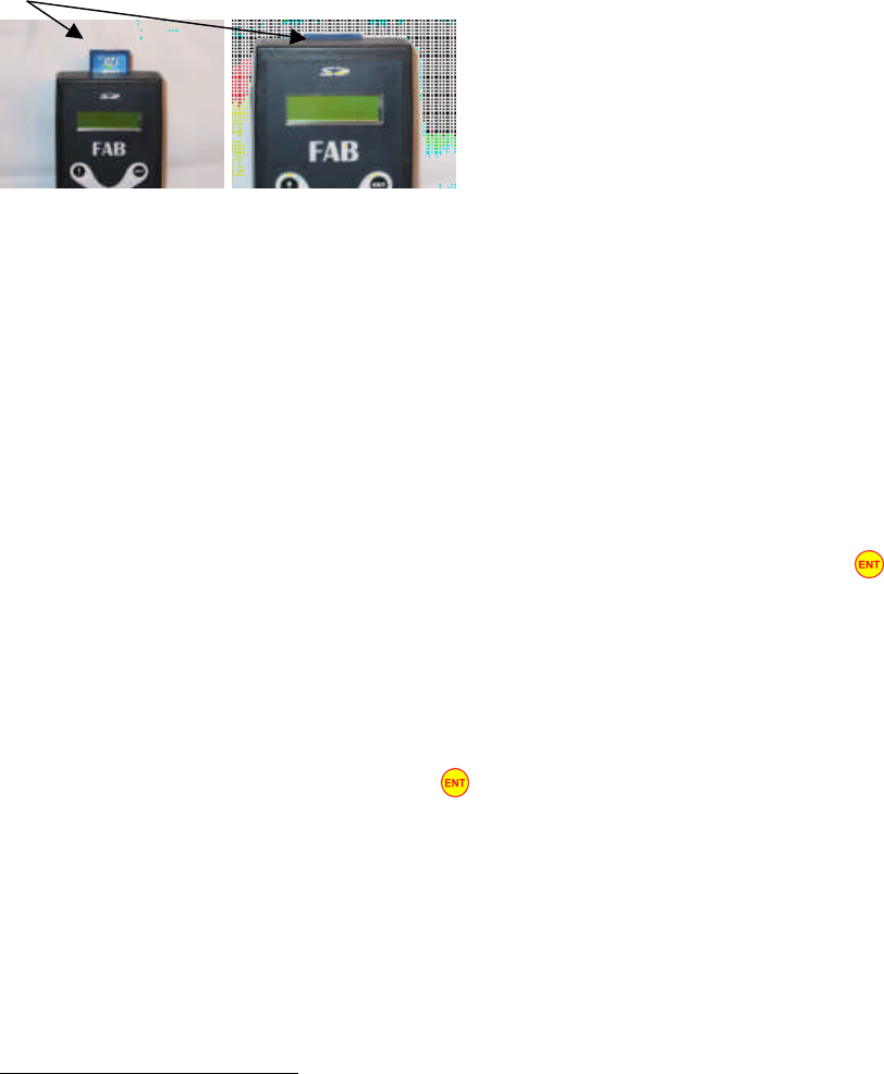
10
the card if it does not slide in easily. You should feel a slight spring resistance near full insertion,
and hear a “click” when the card is fully seated. To remove the card, push the card again and it
should pop out slightly, allowing you to pull it out.
SD Card
Note: The SD memory card should only ever be inserted or removed when the Belt Clip is shut off.
The Belt Clip stores data on the memory card as files with the extension .FRD. One data file is
created for each recording session and will have a unique hexadecimal file name. The file names
are chosen randomly.
As many sessions1 as desired may be recorded. Sessions may be as short or as long as desired.
Stopping one session and starting a new one is an excellent way to keep track of various phases of
an assessment.
NOTE: Try to avoid sessions over 45-60 minutes in length, as viewing long sessions on the
computer is slow. Optimal recoding periods for ease of viewing is 15 minutes or less.
1. To record data, navigate to the “Record Data” screen on the main menu. Press the button to
begin the recording process. You will immediately see a “Put on sensors, then press ENT.”
screen. Leave the Belt Clip at this screen, but keep it within 10 feet of the sensors, for the time
being—the Belt Clip is sending signals to wake up the sensors.
2. Next attach the FAB sensors to the body. See section 3.1.2.2.2. . Ensure the power plugs are
removed from the sensors.
3. Continue to the next step by pressing the button on the Belt Clip (Hand Held) unit. If all
required sensors are awake and ready for use you will see an “All required sensors ok” screen. If
a sensor is faulty or has not turned ON, the Belt Clip may show a screen that says “Left Arm
sensor missing” or “Lower Back sensor missing”. If you have not waited 30s please do so and
be sure the sensor is fully charged.
4. If there is still a problem with some of the sensors you may either continue to record data
(missing a required sensor). If all sensors are ready to go, the Belt Clip screen will display “All
required sensors okay” and “Push ENT for the self timer”.
1 On a memory card formatted using the FAT or FAT16 file system, a maximum of 512 sessions may be recorded on a
memory card before they are transferred to the computer. If the memory card is formatted with FAT32, the number of
session is limited only by the size of the memory card..
11
5. Proceed to the next step by pressing the button. You will now see the display start to count
down from 12. This 12-second interval allows you to assume the neutral position. You MUST
ensure a neutral position is reached by the end of the timer. Make sure your arms and legs are
straight, feet pointing forward and palms towards your thighs. Stand up straight with shoulders
back and level, but do not arch your back. When the timer expires the FAB system calibrates the
neutral position when you hear a long beep. Please stay stationary for the entire long beep.

12
NOTE: You may have to re-calibrate the neutral position if the Belt Clip indicates there was a
problem during calibration. Simply press the button and repeat the previous step.
6. Follow the steps outlined on the Hand Held unit and stand on your left foot only. Ensure that
your entire weight is evenly distributed on your left foot (not concentrated on your heel or your
toes) and press the button. Please stay standing on the left foot until the sampling period is
finished. The sampling period is approximately 1 second long, and you will be asked to stand on
your other foot when sampling is done.
7. Next stand on your right foot and press the button. Please stay standing on the right foot for
the entire sampling period. Note: If you do not have or do not wish to use the foot sensors then
you may press the button to skip calibrating the Foot Sensors; please follow the instructions
provided by your health care professional.
NOTE: You may have to re-calibrate the foot sensors if the Belt Clip indicates there was a problem
during calibration. If you get an error while calibrating the foot sensors you may see a “LF & RF
swapped?” screen. Please verify the foot sensors are attached to the body correctly and the foot
transducers are plugged into the foot sensors. Simply press the button to repeat the previous
step (re-calibrate the foot sensors) or press the button to ignore. Also if there is a problem with
a foot transducer the Belt Clip may display “Left insole bad!” or “Right insole bad!” . Please verify
that the insoles are properly plugged all the way into the foot sensors. Press the button to repeat
the previous step (re-calibrate the foot sensors) or press the button to ignore.
8. The next step is to select a test you wish to perform or use the default test of the FAB system.
Use the and buttons to navigate the different tests or press the button to start the timer
for the selected test. The Belt Clip will display a hint in this regard for a few seconds, or until
you press the button. You are now ready to move freely and FAB will record your
movements. Pressing the button again will stop the timer for the selected test.
NOTE: If there is no “tests” file on your memory card you will not be able to scroll through the
different tests. FAB will still record your movements even if you have not selected a test.
9. The Belt Clip will continue to record data until it is made to stop. To stop a session, press the
button. You will be asked to verify stopping a session—press the button to confirm.
Another session may also be started if there is room on the memory card and adequate power in
the batteries. Sometimes, it may be desirable to stop and start a new session for organizational
purposes. You may reach the main menu and/or shut off the Belt Clip by pressing the button
a few times if desired. Always shut off the Belt Clip before removing or inserting the memory
card.
NOTE: Occasionally an error will occur during data collection. Please see 3.1.2.1. Data Collection
Error Handling for more details.

13
3.1.2.1. Data Collection Error Handling
Occasionally an error or warning will occur during data collection. If an error is encountered the
Belt Clip will display an “(ERRORS—Check?)” message, if a warning is encountered a
“(LowBat—Check?)” message will be displayed. The Belt clip will provide an audible sound if it
encounters an error or warning condition. There are 3 kinds of errors that could occur when
recoding data:
1. A momentary radio drop-out between a sensor and the Belt Clip,
2. Complete sensor failure or
3. A slow memory card error.
There is only 1 warning condition: low battery voltage in a sensor.
3.1.2.1.1. Momentary Radio Drop-out Error
As before, if you encounter the “(ERRORS—Check?)” message on the Belt Clip display as well as
hear repetitive beeping, an error has occurred while collecting data. To display a list of sensors that
encountered a failure press the button. For example if the Right Arm sensor failed you will see
“Sensor Problems: RA (still bad)”. This indicates a sensor has stopped responding due to low
battery voltage, hardware failure or being too far away from the Belt Clip. At this point you may
press the button to continue with the test or press the button to end the session. If you press
the button you may continue with your current test; however, the Belt Clip display will continue
to show the “(ERRORS—Check?)” message but not sound the buzzer. Also there will be no data
collected from the failed sensor.
NOTE: If there was a long interruption in radio communication the FAB system may detect this as
a failed sensor. If the “failed” sensor comes back online during data collection and another radio
drop-out occurs, the audible buzzer will sound and the error message will continue to be displayed.
You may press the button to continue with the test or press the button to end the session. If
you press the button you may continue with the session as normal but there will be a significant
period where no data was collected from the “failed” sensor.
It is also possible to get a combination of momentary radio interference and failed sensors. For
example if the Right Arm sensor experienced a momentary radio drop-out and the Left Arm sensor
failed, pressing the button will display “Sensor Problems: LA (still bad)” then “Sensor
Problems: RA (okay now)”. Pressing the button will silence the error buzzer for the Left Arm
but allow the buzzer to sound if another momentary radio drop-out was detected for the Right Arm.
In fact, viewing the problem list will only silence the buzzer until any sensor experiences another
radio drop-out. Each sensor that is “INCLUDED” in the sensor list is handled separately by the
Belt Clip.
3.1.2.1.2. Sensor Failure Error
As before, if you encounter the “(ERRORS—Check?)” message on the Belt Clip display as well as
hear repetitive beeping, an error has occurred while collecting data. To display a list of sensors that

14
encountered a failure press the button. For example if the Right Arm sensor failed you will see
“Sensor Problems: RA (still bad)”. This indicates a sensor has stopped responding due to low
battery voltage, hardware failure or being too far away from the Belt Clip. At this point you may
press the button to continue with the test or press the button to end the session. If you press
the button you may continue with your current test; however, the Belt Clip display will continue
to show the “(ERRORS—Check?)” message but not sound the buzzer. Also there will be no data
collected from the failed sensor.
NOTE: If there was a long interruption in radio communication the FAB system may detect this as
a failed sensor. If the “failed” sensor comes back online during data collection and another radio
drop-out occurs, the audible buzzer will sound and the error message will continue to be displayed.
You may press the button to continue with the test or press the button to end the session. If
you press the button you may continue with the session as normal but there will be a significant
period where no data was collected from the “failed” sensor.
It is also possible to get a combination of momentary radio interference and failed sensors. For
example if the Right Arm sensor experienced a momentary radio drop-out and the Left Arm sensor
failed, pressing the button will display “Sensor Problems: LA (still bad)” then “Sensor
Problems: RA (okay now)”. Pressing the button will silence the error buzzer for the Left Arm
but allow the buzzer to sound if another momentary radio drop-out was detected for the Right Arm.
In fact, viewing the problem list will only silence the buzzer until any sensor experiences another
radio drop-out. Each sensor that is “INCLUDED” in the sensor list is handled separately by the
Belt Clip.
3.1.2.1.3. Slow Memory Card Error
The Belt Clip monitors the speed of the memory card while recording data. If the memory card is
too slow (and therefore missing data), the Belt Clip will emit a long beep and display “(SD Card
Slow)” on the display. In that case, obtain a faster card from your health professional. (Note: The
data being recorded when the Slow Memory Card Error occurred is still usable, but the recorded
motions may be jerky).
3.1.2.1.4. Low Battery Voltage Warning
While recording data you may encounter a “(LowBat—Check?)” message on the Belt Clip display
as well as hear a repetitive beeping. To display a list of sensors that have low battery voltage, press
the button. For example if the Right Arm sensor has a low battery the Belt Clip will display
“Low Battery: RA (still low)”. Press the button to continue with the test or press the button
to end the session. After pressing the button you may continue with your test as normal. The
“(LowBat—Check?)” message will still be displayed on the Belt Clip display but no audible sound
will be heard. If there is another sensor with low battery voltage the Belt Clip will again display the
“(LowBat—Check?)” message and sound the buzzer.
NOTE: It is strongly recommended you finish the current test quickly and re-charge the FAB
system. The sensors have only a short amount of operation time before they shut off due to low
battery voltage.
15
3.1.2.2. Attaching Sensors to the Body
The FAB Sensors pick up movement by using the Earth’s magnetic and gravitational fields. They
must be securely attached to various points on the subject in a manner that does not restrict natural
movement; the sensors must move with the subject but not shift during data collection.
3.1.2.2.1. Sensor Orientation
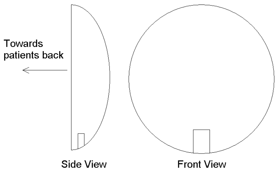
The Lower Back Sensor (Sensor ID 4) must be oriented with the power jack (located in the middle
of the sensor) facing down (towards the ground) and the curved surface of the sensor box facing
away from the body (see Figure 2). The exact orientation of the leg and arm sensors is not critical
as long as they remain in their original positions during data recording. The Lower back sensor
position is more critical; it must be aligned vertically and horizontally with respect to the spine for
proper operation.
Figure 2: Sensor Orientation Side View and Front View
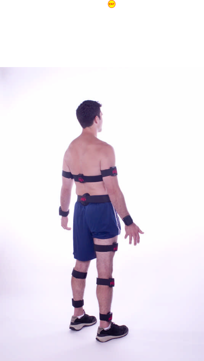
3.1.2.2.2. Sensor Locations
The sensors should be located on the body as follows (ensure the power plug is removed from the
sensor):
16
• Arm sensors should be attached to the outside of each arm just above the elbow.
• The lower back sensor should be attached to the centre of the back at belt height or just above
the top of the butt crack.
• The upper back sensor should be attached to the centre of the back 3 to 4 inches directly above
the lower back sensor.
• The Belt Clip should be located on the left hip or held near (within 2 or 3 feet) of the subject.
Do not cover the upper edge (where the memory card is located) with any part of your body or
with metal objects.
• Leg sensors should be attached just above the knee on the outer portion of the thigh.
• The wrist sensors should sit on the boney prominences between the forearms and the backs of
the hands.
• The calf sensors should sit on the plateau of the tibia just under the knee, on the inboard side of
the calf.
• The foot transducers should be located inside the shoes and the foot sensors attached to the legs
near the ankles. Plug the foot transducers into their respective foot sensors.
NOTE: The Foot sensors have two jacks--one is for the foot transducer and the other is for
charging the Foot Sensors. Please ensure the foot transducers fit into the shoes properly. Both
transducers are the same so one of them will have to be flipped to fit inside the shoe. The Foot
Sensors turn ON when the transducers are plugged in and the power plugs removed.
3.1.3. Setting the Date and Time
See section 2.2. Date and Time Setup
3.2. Clinician Mode
To enter “Clinician Mode” press and hold the and buttons simultaneously when the Belt Clip
shows a blank screen. The Belt Clip will beep and display “Clinician Mode” to confirm your
request. After this confirmation the Belt Clip will automatically bring you to the main menu.
“Clinician Mode” has 2 main functions: Sensor List and Record Data.
3.2.1. Setting up the Sensor List
Setting the sensor list allows you to define which sensors to include in the test and which sensors to
exclude from the test. To include or exclude a sensor from the test, navigate to the “Sensor List”
screen by using the and buttons. Press the button, this will take you to the sensor
include/exclude list. The next screen will allow you to include or exclude a sensor from the test.
Use the button to toggle a sensor between “Included” or “Excluded”. To include or exclude
other sensors, use the and buttons to change sensor ID’s. To save the configuration, press
the button at any time. The sensor list is now set up and stored on the memory card.
17
3.2.2. Recording Data
See section 3.1.2. Recording Data. The Clinician mode “Record Now” function is similar to the
Data Recording mode “Record Data” menu, but assumes a knowledgeable professional is operating
the Belt Clip in a clinical setting. Therefore, there is no 12-second self-timer for calibration of the
neutral position. Rather, it is required that the patient is in neutral position before beginning to
record a session (the Belt Clip will still provide instructions to guide you through attaching the
sensors and calibrating for neutral).
1. To enter “Record Data” mode navigate to the “Record Now?” screen on the main menu. Press
the button to begin the recoding process. You will immediately see “Attach sensors, then
press ENT.” or “No Memory Card or Card Problem” screen. If you encounter the “No Memory
Card or Card Problem” screen ensure a working Memory Card is properly installed in the Belt
Clip. If you encounter the “Attach sensors, then press ENT.” leave the Belt Clip at this screen
so it can wake up the sensors while you attach them to the subject.
2. Next attach the FAB sensors to the subject’s body. See section 3.1.2.2.2. . Ensure the power
plugs are removed from the sensors.
3. Continue to the next step by pressing the button on the Belt Clip (Hand Held) unit. A
marquee-style status line will scroll across the screen, indicating the status of each sensor.
Sensors which were configured to be excluded (see 3.2.1. Setting up the Sensor List) will show
“--” instead of their two-letter abbreviations. If a sensor is faulty or has not yet awakened, the
Belt Clip will show it as offline (e.g. “LWoffl”). If you have not waited 30s please do so and be
sure the sensor is fully charged. If there is still a problem with some of the sensors you may
either continue to record data (missing a required sensor) or call Russell McNeil for
compensation. Sensors with low-batteries will be indicated (e.g. “LWlbat”). If all sensors are
ready to go the Belt Clip screen will display the required sensors as okay (e.g. “LWokay”).
4. Proceed to the next step by pressing the button. You will now see the display “Put patient in
neutral position” and “then push ENT to start recording. You MUST ensure a neutral position is
reached before continuing.
5. After pressing the button, the Belt Clip will display “Calibration in 5 seconds…”. The FAB
system then calibrates the neutral position when you hear a long beep. Please ensure the patient
stays stationary for the entire long beep (neutral calibration period).
Note: You may have to re-calibrate the neutral position if the Belt Clip indicates there was a
problem during calibration. Simply press the button and repeat the previous step or press the
button to ignore the errors and continue. It is STRONGLY recommended that you calibrate
the neutral position correctly. If you do not calibrate neutral position correctly there may be
problems with the processed readings.
6. Follow the steps outlined on the Hand Held unit and have the subject stand on his or her left foot
only. Next press the button. Please ensure the subject remains standing with all of his or her
weight evenly distributed on the left foot until the sampling period is finished. The sampling
period is approximately 1 second long.

18
7. Next have the subject stand on his or her right foot and press the button. Please ensure the
subject remains standing on the right foot for the entire sampling period. If the foot sensors are
not being used, then you may press the button to skip calibrating the Foot Sensors.
NOTE: You may have to re-calibrate the foot sensors if the Belt Clip indicates there was a problem
during calibration. If you get an error while calibrating the foot sensors you may see a “LF & RF
swapped?” screen. Please verify the foot sensors are attached to the body correctly and the foot
transducers are plugged into the foot sensors. Simply press the button to repeat the previous
step (re-calibrate the foot sensors) or press the button to ignore. Also if there is a problem with
a foot transducer the Belt Clip may display “Left insole bad!” or “Right insole bad!” . Please verify
that the insoles are properly plugged all the way into the foot sensors. Press the button to repeat
the previous step (re-calibrate the foot sensors) or press the button to ignore.
8. The next step is to select a test you wish to perform or use the default test of the FAB system.
Use the and buttons to navigate the different tests or press the button to continue. The
subject may move freely and FAB will record his or her movements. Just be sure to keep the
Belt Clip close to (within 2 or 3 feet of) the subject.
NOTE: If there is no “tests” file on your memory card you will not be able to scroll through the
different tests. FAB will still record the subject’s movements even if you have not selected a test.
9. The Belt Clip will continue to record data until it is made to stop. To stop a session, first press
the button to stop the timer for the current test, then press the button. You will be asked
to verify stopping a session—press the button to confirm. Another session may also be
started if there is room on the memory card and adequate power in the batteries. Sometimes, it
may be desirable to stop and start a new session for organizational purposes. You may reach the
main menu and/or shut off the Belt Clip by pressing the button a few times if desired.
Always shut off the Belt Clip before removing or inserting the memory card
NOTE: Occasionally an error will occur during data collection. Please see 3.1.2.1. Data Collection
Error Handling for more details.