NEO ELECTRONICS NAS-DS01Z Contact sensor User Manual NAS DS01Z
SHENZHEN NEO ELECTRONICS CO.,LTD Contact sensor NAS DS01Z
User manual
1
Instruction Manual
Contact Sensor
Thank you for your support
Please read the instruction manual carefully before operating
Please keep the instruction manual after reading
Shenzhen NEO Electronics Co., LTD
Model Name:NAS-DS01Z
Brand:NEO Coolcam
2
Product Introduction
Contact sensor is an intelligent security equipment that can transmit the Z-Wave
network which has particular frequency. In the Z-Wave network communications,
contact sensor can be connected to any Z-wave main controller. The contact sensor
can send messages to the Z-wave main controller, and realize association with other
devices through the Z-wave main controller. Different countries or areas, the radio
frequency is different.In the communication with the Z-wave main controller,
the contact sensor can send messages to the Z-wave main controller, but it can
not receive messages from the Z-wave main controller. When alarm is triggered, the
contact sensor sends messages to the Z-wave main controller, the Z-wave main
controller will displays the current status of contact sensor, so the contact sensor can
associate with other devices. Contact sensor is battery powered, is small and can be
installed on the window or door easily. When the door or window is open, the contact
sensor is triggered and linkage alarm realized.
Technical parameters
Power: CR14250 x1
Standby current: 1uA
Battery life: 10 years
Radio Protocol: Z-wave
Radio Frequency: 868.4MHz EU; 908.4MHz US; 921.4MHz ANZ; 869.2MHz
RU
Wireless distance:50m
Operation temperature: 0-40℃
Storage temperature: 0-60℃
Size: Contact sensor main body (L x W x H): 70mmx20mmx20mm
Contact sensor deputy body (L x W x H): 40mmx11mmx11mm
Technical Information
Install on the door or window.
Battery powered.
Easily install with screws or sticker.
Associate with other devices through the gateway.
Compatible with any Z-Wave network.
3
Product Configuration
Product List
Contact sensor main body 1pc
Contact sensor deputy body 1pc
Battery 2pcs
Screw 6pcs
Screw stopper 6pcs
Sticker 2pcs
Instruction manual 1pc
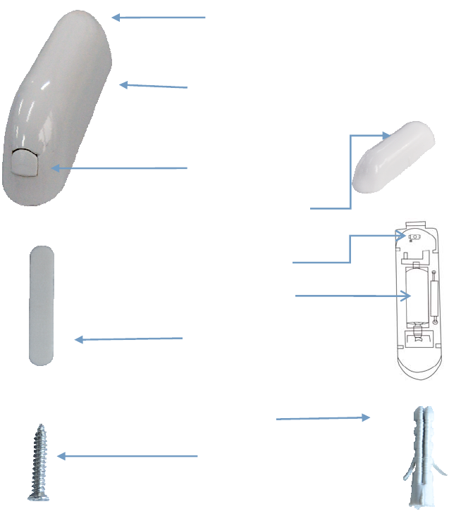
Contact sensor main body
LED li
g
ht
Contact sensor deputy body
Sticker
Screw stopper
Screw
The code button
Battery
Disassemble button
4
Including Sensor (contact sensor) to Z-Wave Network
The contact sensor can be included to the Z-wave network by pressing the code button.
1) Disassemble the contact sensor main body and insert the battery into the contact
sensor. Make sure the device is located within the direct range of the controller.
2) Set the controller into the learning mode (see mail controller’s operating manual).
3) Quickly, triple click the code button, LED light will flash for 5 times.
4) Contact sensor will be detected and included in the Z-Wave network.
5) Wait for the main controller to configure the sensor.
Excluding Sensor (contact senor) from Z-Wave Network
1) Make sure the sensor is connected to power source.
2) Set the main controller into the learning mode (see main controller’s operating
manual).
3) Quickly, triple click the code button,LED light will flash for 5 times.
4) Wait for the main controller to delete the sensor.
5
Installation Steps
Contact sensor Installation
Battery Installation
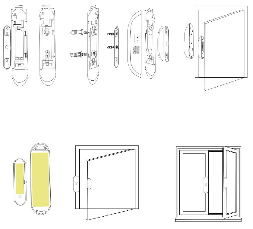
Contact sensor Installation
Option One
Disassemble the contact sensor main body and take out battery, fix it on the door with
screws.
Disassemble the contact sensor deputy body and fix it on the corresponding door
frame position
Option Two
Put the sticker on the bottom of contact sensor to fix it on the wall
NOTE
When installing the contact sensor, contact sensor deputy body must be installed on
the bulge side of the Contact sensor main body.
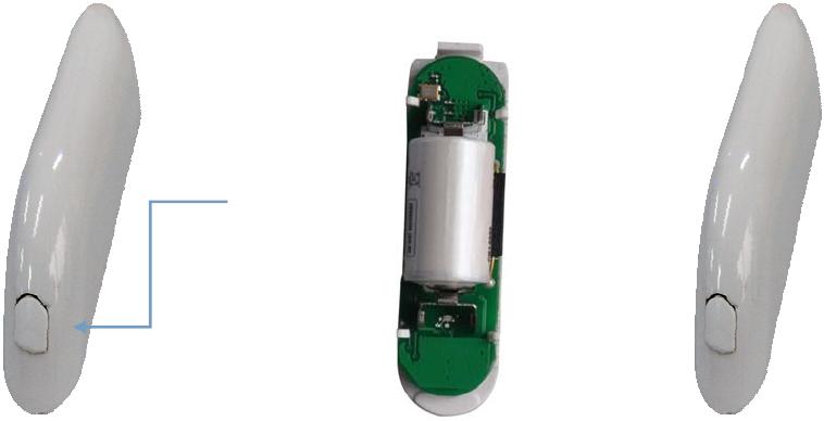
Battery Installation
6
Disassemble the contact sensor Install battery Assemble the contact
main body sensor main body
Disassemble from here
7
Tips
When the door is closed, and the distance between the contact sensor main body
and the contact sensor deputy is less than 2cm, the alarm gateway displays the
door is closed perfectly.
When the door is opened, the distance between the contact sensor main body and
the contact sensor deputy body is more than 2cm, LED light flash and contact
sensor sends messages to the alarm gateway, the alarm gateway displays the
door is open and alarms.
Valid distance of contact sensor is 2cm, so when install, please pay attention to
the trigger surface, it is triggered by point to point.
Make sure of that contact sensor is in the alarm gateway’s network.
The status of LED
1. When the contact sensor is triggered, LED light flashes red for 1 times.
2. When the contact sensor installs battery, LED light will flash red for 5 times.
3. Quickly, triple click the code button ,add the contact sensor to the Z-WAVE network
or delete contact sensor from Z-WAVE network , LED light flashes red for 5 times.
4. Press on the code button for 10 seconds, the contact sensor will be restored to factory
default settings, LED light flashes red for 1 times.
5. In the normal condition, the LED light keeps being out.
Associations
This has the effect that when the sensor is triggered, all devices associated with the
sensor will receive the relevant reports. Through an association the sensor may
control another Z-Wave network devices, e.g. the alarm device, wall plug, lamp etc.
The Contact Sensor supports two linkage groups:
Linkage group 1 is assigned to the device status - sending the BASIC SET control
frame to the associated devices having detected motion.
Linkage group 2 reports relay's status to just one device, Z-Wave network's main
controller by default. It's not recommended to modify settings of this association
NOTE
Contact Sensor linkage with other devices through Z-wave network directly, alarm
gateway or Z-wave controller does not take part in such communication.
8
Restore the Sensor (contact sensor) to Factory Default Settings
Reset will delete all information on the Z-Wave network or Z-Wave controller, and
restore the sensor to factory default settings.
1. Remove the cover of contact sensor main body.
2. Make sure the sensor is connected to power source.
3. Press and hold the reset button for 10 seconds, LED light will flash red for 1 time.
4. Release the button.
NOTE
When the Contact Sensor is being restored to factory default settings, please make
sure power source is connected.
Battery Usage Tips
Battery life of the contact sensor is approximately 10 years at factory default settings.
The current battery level is displayed in the gateway. Red battery icon means the
battery needs replaced. In order to avoid tamper detection, while replacing the battery,
please disconnect the association of the contact sensor with other devices.
Note
Contact sensor is battery powered. Using batteries other than specified may result in
explosion. Dispose of properly, please observe environmental protection rules.
Advanced Configuration
1. Configuring the OFF Delay
This configuration parameter that can be used to adjust the amount of delay before the
OFF command is transmitted. This parameter can be configured with the value of 0
through 65535, where 0 means send OFF command immediately and 65535 means
65535 seconds of delay.
Function: On/Off Duration.
Parameter Number: 1.
Parameter Size: 2 Byte
Available Settings:0-65535 (in seconds, each 1s).
Default Setting: 30 (s)
2. Basic Set Level
Basic Set Command will be sent where contains a value when the door/window is
opened or closed, the receiver will take it for consideration; for instance, if a lamp
module received the Basic Set Command of which value is decisive as to how bright
9
of dim level of lamp module shall be.
Function: Basic Set
Parameter Number: 2
Parameter Size: 1 Byte
Available Settings:0, 1 - 99 or 255
0 – OFF, Alarm cancelling or turning a device off
1 - 99 or 255 – ON (Binary Switch Device)
Dim Level (Multilevel Switch Device)
Default Setting: 99
Command Classes
This Sensor(Door/Windows Detector) supports Command Classes as Below:
* COMMAND_CLASS_ZWAVEPLUS_INFO (V2)
* COMMAND_CLASS_VERSION (V2)
* COMMAND_CLASS_MANUFACTURER_SPECIFIC (V2)
* COMMAND_CLASS_DEVICE_RESET_LOCALLY (V1)
* COMMAND_CLASS_POWERLEVEL (V1)
* COMMAND_CLASS_BATTERY (V1)
* COMMAND_CLASS_ASSOCIATION (V2)
* COMMAND_CLASS_ASSOCIATION_GRP_INFO (V1)
* COMMAND_CLASS_WAKE_UP (V2)
* COMMAND_CLASS_NOTIFICATION (V4)
* COMMAND_CLASS_SENSOR_BINARY (V2)
* COMMAND_CLASS_CONFIGURATION (V1)

10
Guarantee
1. The Guarantee is provided by Shenzhen NEO Electronics Co., Ltd (hereinafter
“Manufacture” ).
2. The Manufacturer is responsible for equipment malfunction resulting from
physical defects (manufacturing or material) of the device for 12 months from the
date of its purchasing.
3. During the Guarantee period, the Manufacturer shall remove any defects, free of
charge, by repairing or replacing.
4. In special cases, when the device cannot be replaced with the device of the same
type (e.g. the device is no longer available in the commercial offer), the
Manufacturer may replace it with a different device having technical parameters
similar to the faulty one. Such activity shall be considered as fulfilling the
obligations of the Manufacturer. The Manufacturer shall not refund money paid
for the device.
5. The guarantee shall not cover:
mechanical damages (cracks, fractures, cuts, abrasions, physical deformations
caused by impact, falling or dropping the device or other object, improper use
or not observing the operating manual);
damages resulting from external causes, e.g.: flood, storm, fire, lightning,
natural disasters, earthquakes, war, civil disturbance, force majeure,
unforeseen accidents, theft, water damage, liquid leakage ,battery spill,
weather conditions, sunlight, sand, moisture, high or low temperature, air
pollution
damages caused by malfunctioning software, attack of a computer virus, or by
failure to update the software as recommended by the Manufacturer;
FCC NOTE:
This device complies with Part 15 of the FCC Rules.
Operation is subject to the following two conditions: (1) this device may not cause
harmful interference, and (2) this device must accept any interference received,
including interference that may cause undesired operation.
THE MANUFACTURER IS NOT RESPONSIBLE FOR ANY RADIO OR TV
INTERFERENCE CAUSED BY UNAUTHORIZED MODIFICATIONS OR
CHANGE TO THIS EQUIPMENT. SUCH MODIFICATIONS OR CHANGE
COULD VOID THE USER’S AUTHORITY TO OPERATE THE EQUIPMENT
Shenzhen NEO Electronics Co., LTD
Address: 6TH Floor, Building No.2, Laobing Industrial Park, Tiezhai Road Xixiang,
BaoAn District, Shenzhen, China.
Http://www.szneo.com
Tel: +86-4007-888-929
Fax: +86-755-29667746
E-mail: support@szneo.com