NEO ELECTRONICS NAS-PD02Z Motion Sensor(PIR) User Manual NAS PD02Z
SHENZHEN NEO ELECTRONICS CO.,LTD Motion Sensor(PIR) NAS PD02Z
User manual
Instruction Manual
Motion Sensor(PIR)
Model Name: NAS-PD02Z
Thank you for your support
Please read the instruction manual carefully before operating
Please keep the instruction manual after reading
Shenzhen Neo Electronics Co., LTD
Product Introduction
PIR is a passive infrared detector or physical sensor, the sensor doesn’t emit any energy but only
passively receive and detect infrared radiation from outside. Under room temperature, all items
have radiation. Human beings are warm-blooded animal with stable infrared radiation, are most
easily to be detected. That’s why we also call it body sensor. PIR send messages via Z-wave
network to the Z-Wave main controller. In the Z-Wave network communications, PIR can be
connected to any Z-wave main controller,Different countries or areas, the radio frequency is
different of the Z-wave network. In the communication between the PIR and Z-wave main
controller, PIR can only send messages, not be able to receive messages. When the PIR is
triggered, PIR will send message to the Z-wave main controller, and associate devices to work
through the Z-Wave main controller. The PIR is battery powered, is small and can be installed
easily.
Technical Parameters
Power supply: CR123A x 1
Standby current: 15uA
Battery life: 7 years
Radio Protocol: Z-wave
Radio Frequency: 908.42MHz
Detection range: 7 meters
Viewing angle: 90 degree
Operation temper: 0-40℃
Storage temperature: 0-60℃
Size (D x W x H): 45mm x 45mm x 48mm
Technical Information
Use passive IR sensor to detect what is moving.
When the PIR is triggered, LED light flashes in the detection area.
Easily install with screws or sticker on the wall or the table.
When there are people or animal that is moving in the PIR detection area, PIR
will send alarm messages to the Z-wave main controller.
Compatible with any Z-Wave main controller.
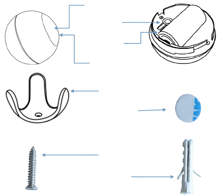
Product Configuration
Product List
PIR 1pc
Holder 1pc
Battery 1pc
Screw 2pcs
Screw stopper 2pcs
Sticker 1pc
Instruction manual 1pc
Code button
Holder
Sticke
r
Screw
Battery
Screw sto
pp
e
r
LED li
g
ht
Inductive area
Including Sensor (PIR) to Z-Wave Network
The PIR can be included to the Z-wave network by pressing on the code button.
1) Disassemble the PIR main body and insert the battery into the contact sensor. Make
sure the device is located within the direct range of the controller.
2) Set the controller into the learning mode (see mail controller’s operating manual).
3) Quickly, triple click the code button, LED light will flash red for 5 times.
4) PIT will be detected and included in the Z-Wave network.
5) Wait for the main controller to configure the PIR.
Excluding Sensor (PIR) from Z-Wave Network
1) Make sure the sensor is connected to power source.
2) Set the main controller into the learning mode (see main controller’s operating
manual).
3) Quickly, triple click the code button,LED light will flash red for 5 times.
4) Wait for the main controller to delete the sensor.
Installation Steps
Holder Installation
Battery Installation
Fix PIR on the holder
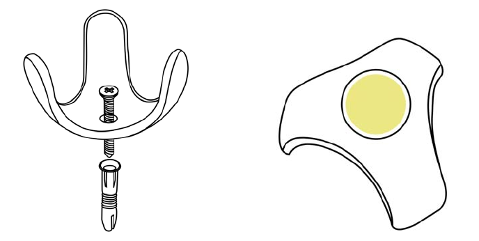
Holder Installation
Option One Option Two
Fix the holder with screws and screw stopper Fix the holder with double-sided
adhesive
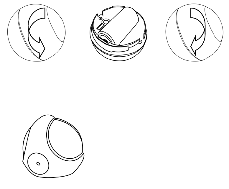
Battery Installation
Open the PIR Install the battery Close the PIR
Fix PIR on the Holder
Detection range and Working conditions
PIR has to be installed in a corner of the room or perpendicularly to the doors.
Actual detection range of the sensor can be influenced by environment conditions.
Should false alarms be reported, check for any moving objects within the sensor’s
detection area, such as trees blowing in the wind, cars passing by, windmills. False
motion alarms may be caused by moving masses of air and heat as well. If the device
keeps on reporting false alarms, despite eliminating all of the above-mentioned factors,
install the device in another place.
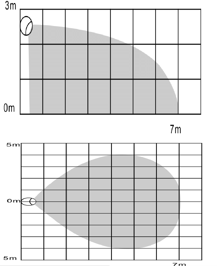
Detection range of PIR shown in the following picture
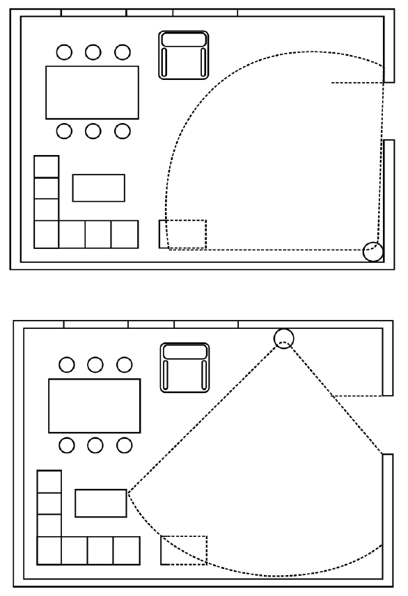
Working condition
If there is someone moving within the detection area, alarm triggered, and LED lights flash in the
inductive area at the same time.
Work schematic diagram of PIR shown in the following picture
Tips
Make sure the PIR is in the Gateway’s network.
PIR is recommended to be fixed at the height of 2.0-2.2 meters off the ground.
When install PIR, please keep it far away from the place where the air
temperature changed sensitively, e.g., the neighborhood of air conditioners,
refrigerators, stoves and so on.
Furniture, large bonsai or other spacers shouldn’t be placed within the PIR’s
detection area.
When installing the PIR, please avoid stairs、elevators and other obstructions
within the PIR’s detection area.
After installation of the PIR, please test whether the PIR works properly or not, if
there is false alarm from PIR, please change the location of the PIR.
Association allows for direct communication between Z-Wave network devices.
Main controller does not take part in such communication. Using this mechanism,
PIR may communicate with other devices even when the main controller is
damaged.
The status of LED
1. when the PIR is triggered, LED light flashes red for 2 times.
2. When the PIR installs battery, LED light will flash red for 2
times.
3. Quickly, triple click the code button ,add the PIR to the Z-WAVE network or delete
PIR from Z-WAVE network , LED light flashes red for 5 times.
4. Press on the code button for 10 seconds, the PIR to restore factory settings, LED light
flashes for 1 times.
5. In the normal condition, the LED light keeps being out.
Associations
This has the effect that when the sensor is triggered, all devices associated with the
sensor will receive the relevant reports. Through an association the sensor may
control another Z-Wave network device, e.g. the alarm device, wall plug, lamp etc.
This Sensor supports two association groups.
Association group 1 is assigned the status of the device status - send the BASIC SET
control frame to the associated to the associated devices having detected motion.
Association group 2 reports relay's status to just one device, Z-Wave network's main
controller by default. It's not recommended to modify settings of this association
group.
NOTE
Association allows for direct communication between Z-Wave network devices. Main
controller does not take part in such communication.
Restore the Sensor (PIR Motion detector) to Factory Default Settings
Reset procedure will delete all information on the Z-Wave network and Z-Wave
controller or
Z-Wave Gateway, and restore the sensor to factory default settings.
1. Remove the device cover
2. Make sure the sensor is connected to power source.
3. Press the reset button for 10 seconds, LED will flash.
4. Release the button.
NOTE
When the PIR is being restored factory settings, please make sure power source is
connected.
Battery Usage Tips
Battery life of the contact sensor is approximately 2years at factory default settings.
The current battery level is displayed in the gateway. Red battery icon means the
battery needs replaced. In order to avoid tamper detection, while replacing the battery,
please disconnect the association of the contact sensor with other devices.
Note
Contact sensor is battery powered. Using batteries other than specified may result in
explosion. Dispose of properly, please observe environmental protection rules.
Advanced Configuration
The following information is for someone that has some experience in setting up a
Z-Wave system or someone that has computer software running a Z-Wave controller
or Z-Wave Gateway. Please get familiar with software of Z-Wave controller or
Z-Wave Gateway before getting started.
1. Sensitivity Level Setting
This parameter defines the sensitivity of PIR detector, it is recommended to test the
detector with movements from a farthest end of the coverage area at first time of use.
If movements cannot be detected sensitively, simply adjust the sensitivity level with
this parameter. This parameter can be configured with the value of 1 through 4, where
1 means high sensitivity and 4 means lowest sensitivity.
Function: Sensitivity Level Setting.
Parameter Number: 1.
Parameter Size: 1 Byte.
Available Settings: 1 - 4.
Default Setting: 2.
2. On/Off Duration
This parameter can be determined how long the associated devices should stay ON
status. For instance, this parameter is set to 30(second), the PIR detector will send a
BASIC SET Command to an associated device with value basic set level if PIR
detector is triggered and the associated device will be turned on 30(second) before it
is turned off. This Parameter value must be large than Parameter 6#.
Function: On/Off Duration Setting
Parameter Number: 2
Parameter Size: 2 Byte
Available Settings: 5 - 600(second)
Default Setting: 30
3. Basic Set Level
Basic Set Command will be sent where contains a value when PIR detector is
triggered, the receiver will take it for consideration; for instance, if a lamp module is
received the Basic Set Command of which value is decisive as to how bright of dim
level of lamp module shall be. This
Parameter is used to some associated devices.
Function: Basic Set Level
Parameter Number: 3
Parameter Size: 1 Byte
Available Settings:0, 1- 99 or 255
0 – OFF, Alarm cancelling or turning a device off
1 - 99 or 255 –
ON (Binary Switch Device
Dim Level (Multilevel Switch Device
Default Setting: 99
4. PIR Detecting Function Enabled/Disabled
This parameter can be enabled or disabled the PIR detector detecting function.
Function: Enabled/Disabled PIR Function
Parameter Number: 4
Parameter Size: 1 Byte
Available Settings:0 or 255
0 – Disable PIR Detector Function
255 – Enable PIR Detector Function
Default Setting: 255
5. Ambient illumination Lux Level (Not Complete, Reserved)
This parameter can be set a lux level value which determines when the light sensor is
activated. If the ambient illumination level falls below this value and a person moves
across or within the detected area , PIR detector will send a Z-Wave ON command(i.e.
BASIC_SET value = parameter 3#) to an associated device and activate it.
Function: Lux Level Set
Parameter Number: 5
Parameter Size: 2 Byte
Available Settings: 0 - 1000(Lux)
Default Setting: 100(Lux)
6. Re-trigger Interval Setting
This Parameter can be used to adjust the interval of being re-triggered after the PIR
detector has been triggered. No report will be sent during this interval if a movement
is presented. This Parameter value must be less than Parameter 2#.
Function: Re-trigger Interval Setting.
Parameter Number : 6
Parameter Size:1 Byte
Available Settings:5 ~ 120(s)
Default Setting:10
7. Light Sensor Polling Interval
This Parameter can be set the light sensor measure ambient illumination level interval
time.
NOTE: This Value Must Be less than Wakeup Interval Time.
Function:Light Sensor Polling Interval
Parameter Number:7
Parameter Size:2 Byte
Available Settings:60 - 36000(second)
Default Setting:600(s)
8. Reserved
9. Ambient illumination Lux Level Report
This parameter defines by how much Lux Level must change, in lux, to be reported to
the main controller.
Function:Lux Level Report
Parameter Number:9
Parameter Size:2 Byte
Available Settings:0 - 1000(Lux)
Default Setting: 100(Lux)
Command Classes
This Sensor(Motion Detector) supports Command Classes as Below:
* COMMAND_CLASS_ZWAVEPLUS_INFO (V2)
* COMMAND_CLASS_VERSION (V2)
* COMMAND_CLASS_MANUFACTURER_SPECIFIC (V2)
* COMMAND_CLASS_DEVICE_RESET_LOCALLY (V1)
* COMMAND_CLASS_POWERLEVEL (V1)
* COMMAND_CLASS_BATTERY (V1)
* COMMAND_CLASS_ASSOCIATION (V2)
* COMMAND_CLASS_ASSOCIATION_GRP_INFO (V1)
* COMMAND_CLASS_WAKE_UP (V2)
* COMMAND_CLASS_NOTIFICATION (V4)
* COMMAND_CLASS_SENSOR_BINARY (V2)
* COMMAND_CLASS_CONFIGURATION (V1)
* COMMAND_CLASS_SENSOR_MULTILEVEL (V7)
FCC NOTE:
This device complies with Part 15 of the FCC Rules.
Operation is subject to the following two conditions: (1) this device may not cause
harmful interference, and (2) this device must accept any interference received,
including interference that may cause undesired operation.
THE MANUFACTURER IS NOT RESPONSIBLE FOR ANY RADIO OR TV
INTERFERENCE CAUSED BY UNAUTHORIZED MODIFICATIONS OR
CHANGE TO THIS EQUIPMENT. SUCH MODIFICATIONS OR CHANGE
COULD VOID THE USER’S AUTHORITY TO OPERATE THE EQUIPMENT.

Guarantee
1. The Guarantee is provided by Shenzhen NEO Electronics Co., Ltd (hereinafter
“Manufacture” )
2. The Manufacturer is responsible for equipment malfunction resulting from
physical defects (manufacturing or material) of the device for 12 months from the
date of its purchasing.
3. During the Guarantee period, the Manufacturer shall remove any defects, free of
charge, by repairing or replacing.
4. In special cases, when the device cannot be replaced with the device of the same
type (e.g. the device is no longer available in the commercial offer), the
Manufacturer may replace it with a different device having technical parameters
similar to the faulty one. Such activity shall be considered as fulfilling the
obligations of the Manufacturer. The Manufacturer shall not refund money paid
for the device.
5. The guarantee shall not cover:
mechanical damages (cracks, fractures, cuts, abrasions, physical deformations
caused by impact, falling or dropping the device or other object, improper use
or not observing the operating manual);
damages resulting from external causes, e.g.: flood, storm, fire, lightning,
natural disasters, earthquakes, war, civil disturbance, force majeure,
unforeseen accidents, theft, water damage, liquid leakage ,battery spill,
weather conditions, sunlight, sand, moisture, high or low temperature, air
pollution
damages caused by malfunctioning software, attack of a computer virus, or by
failure to update the software as recommended by the Manufacturer;
Shenzhen NEO Electronics Co., LTD
Address: 6TH Floor, Building No.2, Laobing Industrial Park, Tiezhai Road Xixiang,
BaoAn District, Shenzhen, China.
Http://www.szneo.com
Tel: +86-4007-888-929
Fax: +86-755-29667746
E-mail: support@szneo.com