NEO ELECTRONICS NAS-WR01Z Power plug(US) User Manual NAS WR02Z
SHENZHEN NEO ELECTRONICS CO.,LTD Power plug(US) NAS WR02Z
User manual
Instruction Manual
Power plug
Thank you for your support
Please read the instruction manual carefully before operating
Please keep the instruction manual after reading
Shenzhen NEO Electronics Co., LTD
Model:NAS-WR01Z
Product Introduction
Power plug is an intelligent device that can be controlled remotely by the Z-wave
network and the radio wave which has particular frequency. In the Z-wave network
communications, Power plug can be connected to any Z-wave main controller. In the
radio wave communications, Gateway and Power plug can
send messages to each other through the radio waves. Different countries or areas, the
radio frequency is different.In the communication with gateway,
the power plug can send and receive messages. When press the code button of power
plug, it will send messages to the gateway. The gateway can display the on/off status
of power plug correctly; when the power plug receives messages from the gateway,
the on/off status of the power plug can be switched remotely via mobile phone APP.
The power plug is small and light, very easy to operate.
Technical parameters
Input voltage: 120V AC+/-10% 60Hz
Rated input current: 10A,120V ,60 Hz Continuous load current
16A,120V ,60Hz Instantaneous load current
Rated power: 2500w
Radio Protocol: Z-wave
Radio Frequency: 908.42MHz
Wireless distance:50m
Operation temperature: 0-40℃
Storage temperature:0-60℃
Dimension (D x W x H):
US plug: 43mm x 43mm x 45mm
EU plug: 43mm x 43mm x 65mm
Technical Information
The on and off of the power plug can be switched remotely by mobile phone App.
The working status of the power plug can be viewed through the mobile phone
App
Switching on and off of appliances easily via mobile phone App.
Can Compatible with any Z-Wave main controller.
Product Configuration
Product List
Power plug 1pc
Instruction manual 1pc
Including Sensor (Power plug) to Z-Wave Network
The Power plug can be added to the Z-Wave network by pressing the code button.
1) Plug the power plug in the socket. Make sure the device is located within the direct
range of the main controller.
2) Set the main controller to the learning mode (see main controller’s operating
manual).
3) Quickly, triple click the code button, the device will enter inclusion mode, and the
LED light will flash on and off with green alternately five times within 2 seconds.
4) Power plug will be detected and added to the Z-Wave network.
5) Wait for the main controller to configure the sensor.
Excluding Sensor (Power Plug) from Z-Wave Network
1) Make sure the sensor is connected to power source.
2) Set the main controller to the learning mode (see main controller’s operating
manual)
3) Quickly, triple click the code button
4) Wait for the main controller to delete the sensor
5) If the sensor has been deleted from the Z-wave network, the LED light will flash
five times within 2 seconds
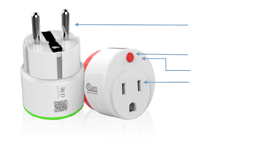
Illustration
The code button
Jack
LED
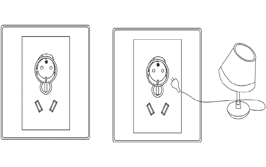
Installation Steps
Plug the power plug in the socket
Plug the load in the power plug
Plug the power plug in the socket Plug the load in the power plug

Tips
Please do not spray water on the power plug.
The on and off of power plug can be switched remotely by mobile phone APP.
The load connected with the power plug shouldn’t exceed 2500w to avoid
damaging of the power plug.
Make sure of that power plug is in the gateway’s network.
The status of LED
1. When the power plug is on, LED light keeps being green.
2. When the power plug is off, LED light keeps being out.
3. Quickly, triple click the code button ,add the power plug to the Z-WAVE network or delete
PIR from Z-WAVE network , LED light flashes red and yellow for 5 times at the same time.
4. Press on the code button for 10 seconds, the PIR to restore factory settings, LED light flashes
red and yellow for 1 times at the same time.
Restore the Sensor (Power Plug) to Factory Default Settings
Reset procedure will delete all information on the Z-Wave network and Z-Wave
controller or Z-Wave Gateway, and restore the sensor to factory default settings.
1. Plug the power plug in the socket.
2. Press and hold the button for 10 seconds, the LED light flashes.
3. Release the button.
When the power plug is reset completely, The LED light will flash on and off
with dark alternately five times within 2 seconds.
NOTE
When the power plug is being restored factory settings, please make sure power
source is connected.
Associations
This has the effect that when the sensor is triggered, all devices associated with the
sensor will receive the relevant reports. Through an association the sensor may
control another Z-Wave network device, e.g. the alarm device, wall plug, lamp etc.
The Wall Plug provides two association groups:
Association group 1 is assigned to Plugs status - On/Off. Allows for receiving control
command from trigger devices whenever the Plug is turned On or Off.
Association group 2 reports relay's status to just one device, Z-Wave network's main
controller by default. It's not recommended to modify settings of this association
group.
Current Load and Energy Consumption
This Plug provides line voltage, current load, power consumption and energy
consumption measuring. These measurement results are sent to Z-Wave Controller or
Z-Wave Gateway.
Voltage – The Supply Power Voltage For Plug.
Current – The Current for the Electric Device Connect to Plug Consumption.
Power – Power Consumed by an Electric Device in an instant, unit: Watt (W).
Energy – Energy Consumed by an Electric Device through a Time Period. Most
commonly measured in Kilowatt-hours (kWh). One kilowatt-hour is Equal to One
Kilowatt of Power Consumed over a Period of One Hour, 1kWh = 1000Wh.
Advanced Configuration
1.Send Meter Report Enable
This parameter defines Disable/Enable meter report measure data to controller.
Function: Meter Report Enable
Parameter Number: 1.
Parameter Size: 1 Byte
Available Settings:0,1.
0 – Disable Report,
1 - Enable Report
Default Setting: 1.
2. Meter Report Interval
This parameter defines interval time (in seconds) that Meter report data to main
controller.
Function: set the upper current threshold.
Parameter Number: 2.
Parameter Size: 2 Byte
Available Settings: 1 – 65535(s).
Default Setting: 300(s)
3. Configure maximum over-load current
This parameter defines maximum current the plug can provide to load that be
connected to plug.
If the current consumed by load greater than maximum current, the plug will cut off
power.
Function: set the upper current threshold.
Parameter Number: 3.
Parameter Size: 1 Byte
Available Settings: 1 – 16 (Ampere).
Default Setting: 13(A).
4. Configure maximum Alarm current
This parameter defines maximum current, if the current plug provide to load great
than this parameter, the plug will send over-current notification to main controller and
the LED will be turn RED, but plug cannot cut-off power. This value must be less
than parameter 3#.
Function: Set Alarm upper current threshold.
Parameter Number: 4.
Parameter Size: 1 Byte
Available Settings: 1 – Parameter #3 (Ampere).
Default Setting: 12(A).
5. Led Display Enable
This parameter defines the LED indication Function ON/OFF. This parameter can be
configured with 0 or 1, where 0 means disable LED indication Function and will
always be turn-off, and 1 means enable LED Function.
Function: LED Enable/Disable
Parameter Number: 5.
Parameter Size: 1 Byte
Available Settings: 0, 1.
Default Setting: 1.
6. Configure power report
This parameter defines by how much power consumed must change to be reported to
the Z-Wave Controller or Z-Wave Gateway, in percents. If the rate of power
consumed change ratio is greater than this parameter, the plug will report the results,
voltage, current, power and energy, that plug measure to Z-Wave Controller or
Z-Wave Gateway.
Function: Power Reporting Setting
Parameter Number: 6.
Parameter Size: 1 Byte
Available Settings: 1 – 100 (%).
Default Setting: 30(%).
7. 7. Remember Relay ON/OFF status
This parameter defined the relay status if remember or not. If remembered, the plug
will restore the relay status last power off when the plug supply power next time.
Function: Remember Relay Status
Parameter Number: 7.
Parameter Size: 1 Byte
Available Settings: 0 - 255
0 – Don’t Remember, the relay will keep OFF when
Plug Supply Power.
Others – Remember the Relay Status.
Default Setting: 255.
8. Configure Plug Time switch Function
This parameter defines the timer function Enable/Disable. This parameter can be
configured with 0 or 1, where 0 means disable time switch function and 1 enable. The
time period will be defined in parameter 9#.If this parameter is Set to 1, and when
turn the plug relay on, the timer in plug start run with time period defined in
parameter #9 and the plug will turn the relay off.
Function: Time switch Configure
Parameter Number: 8.
Parameter Size: 1 Byte
Available Settings: 0, 1
0 – Time switch Disable.
1 – Time switch Enable.
Default Setting: 0
9. Configure Time switch Period
This parameter defines the time period that plug time switch off. This parameter can
be configured 1 ~ 65535(in minutes). If Parameter 9# is set to ‘1’, and relay is turn-on,
the relay will be turn-off after delay this parameter.
Function: Time switch Configure
Parameter Number: 9.
Parameter Size: 2 Byte
Available Settings: 1 ~ 65535 (minutes).
Default Setting: 150(min)
Command Classes
The Plug supports Command Classes as Below:
* COMMAND_CLASS_ZWAVEPLUS_INFO (V2)
* COMMAND_CLASS_MANUFACTURER_SPECIFIC (V2)
* COMMAND_CLASS_VERSION (V2)
* COMMAND_CLASS_ASSOCIATION (V2)
* COMMAND_CLASS_ASSOCIATION_GRP_INFO (V1)
* COMMAND_CLASS_DEVICE_RESET_LOCALLY (V1)
* COMMAND_CLASS_POWERLEVEL (V1)
* COMMAND_CLASS_SWITCH_BINARY (V1)
* COMMAND_CLASS_NOTIFICATION (V4)
* COMMAND_CLASS_METER (V4)
* COMMAND_CLASS_CONFIGURATION (V1)
* COMMAND_CLASS_SWITCH_ALL (V1)
* COMMAND_CLASS_BASIC (V1)
Guarantee
1. The Guarantee is provided by Shenzhen NEO Electronics Co., Ltd (hereinafter
“Manufacture” )
2. The Manufacturer is responsible for equipment malfunction resulting from
physical defects (manufacturing or material) of the device for 12 months from the
date of its purchasing.
3. During the Guarantee period, the Manufacturer shall remove any defects, free of
charge, by repairing or replacing.
4. In special cases, when the device cannot be replaced with the device of the same
type (e.g. the device is no longer available in the commercial offer), the
Manufacturer may replace it with a different device having technical parameters
similar to the faulty one. Such activity shall be considered as fulfilling the
obligations of the Manufacturer. The Manufacturer shall not refund money paid
for the device.
5. The guarantee shall not cover:
mechanical damages (cracks, fractures, cuts, abrasions, physical deformations
caused by impact, falling or dropping the device or other object, improper use
or not observing the operating manual);
damages resulting from external causes, e.g.: flood, storm, fire, lightning,
natural disasters, earthquakes, war, civil disturbance, force majeure,
unforeseen accidents, theft, water damage, liquid leakage ,battery spill,
weather conditions, sunlight, sand, moisture, high or low temperature, air
pollution
damages caused by malfunctioning software, attack of a computer virus, or by
failure to update the software as recommended by the Manufacturer;

FCC NOTE:
This device complies with Part 15 of the FCC Rules.
Operation is subject to the following two conditions: (1) this device may not cause harmful
interference, and (2) this device must accept any interference received, including
interference that may cause undesired operation.
THE MANUFACTURER IS NOT RESPONSIBLE FOR ANY RADIO OR TV
INTERFERENCE CAUSED BY UNAUTHORIZED MODIFICATIONS OR CHANGE
TO THIS EQUIPMENT. SUCH MODIFICATIONS OR CHANGE COULD VOID THE
USER’S AUTHORITY TO OPERATE THE EQUIPMENT.
Shenzhen NEO Electronics Co., LTD
Address: 6TH Floor, Building No.2, Laobing Industrial Park, Tiezhai Road Xixiang,
BaoAn District, Shenzhen, China.
Http://www.szneo.com
Tel: +86-4007-888-929
Fax: +86-755-29667746
E-mail: support@szneo.com
This equipment has been tested and found to comply with the limits for a Class B digital
device, pursuant to part 15 of the FCC Rules. These limits are designed to provide
reasonable protection against harmful interference in a residential installation. This
equipment generates, uses and can radiate radio frequency energy and, if not installed and
used in accordance with the instructions, may cause harmful interference to radio
communications. However, there is no guarantee that interference will not occur in a
particular installation. If this equipment does cause harmful interference to radio or
television reception, which can be determined by turning the equipment off and on, the
user is encouraged to try to correct the interference by one or more of the following
measures:
-- Reorient or relocate the receiving antenna.
-- Increase the separation between the equipment and receiver.
-- Connect the equipment into an outlet on a circuit different from that to which the
receiver is connected.
-- Consult the dealer or an experienced radio/TV technician for help.
RF exposure statement
This equipment complies with FCC radiation exposure limits set forth for an uncontrolled
environment .The device has been evaluated to meet general RF exposure requirement.
The device can be used in portable exposure condition without restriction.