NEO ELECTRONICS NAS-WS01Z Water sensor User Manual NAS WS01Z Manual User

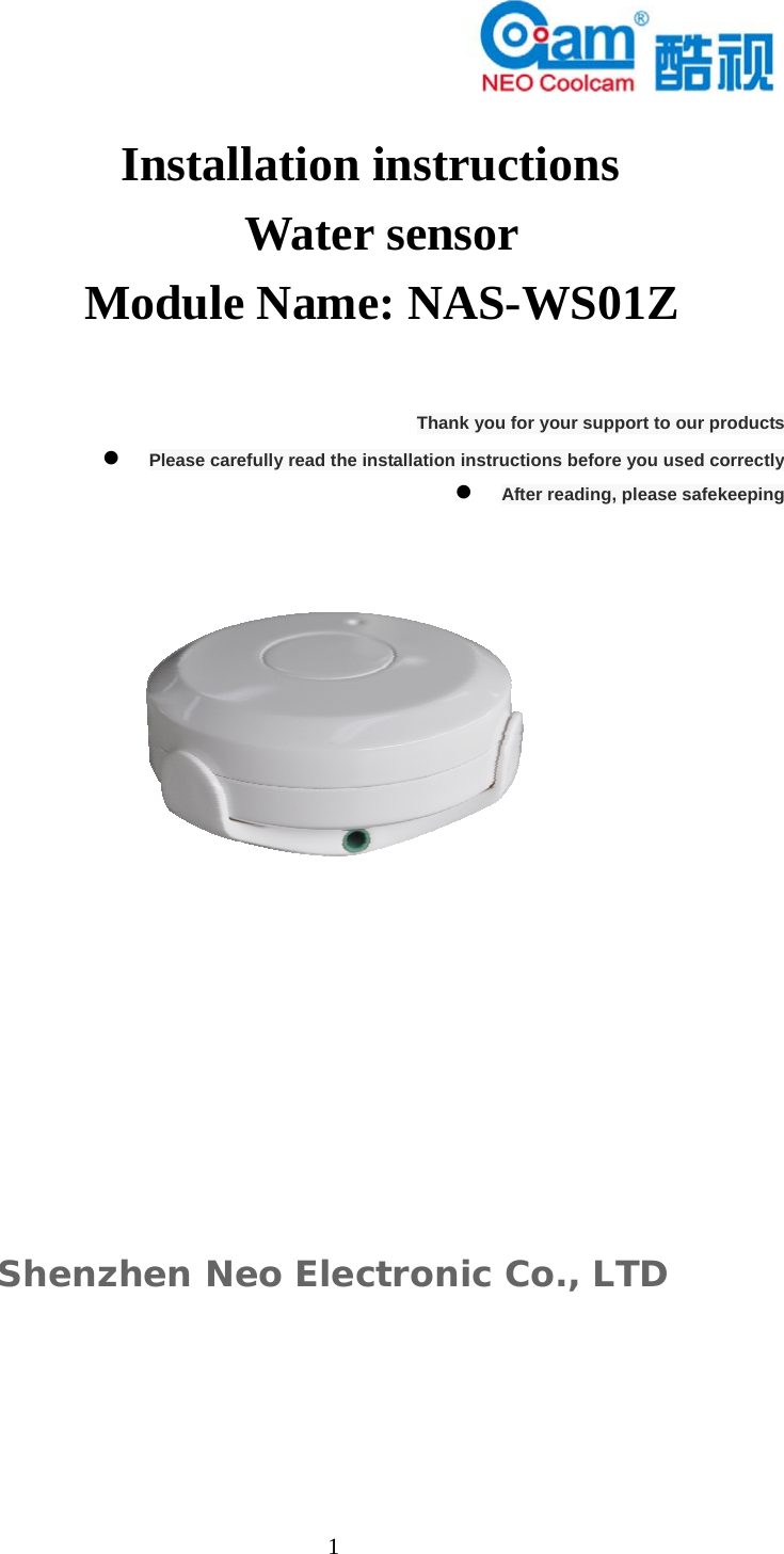
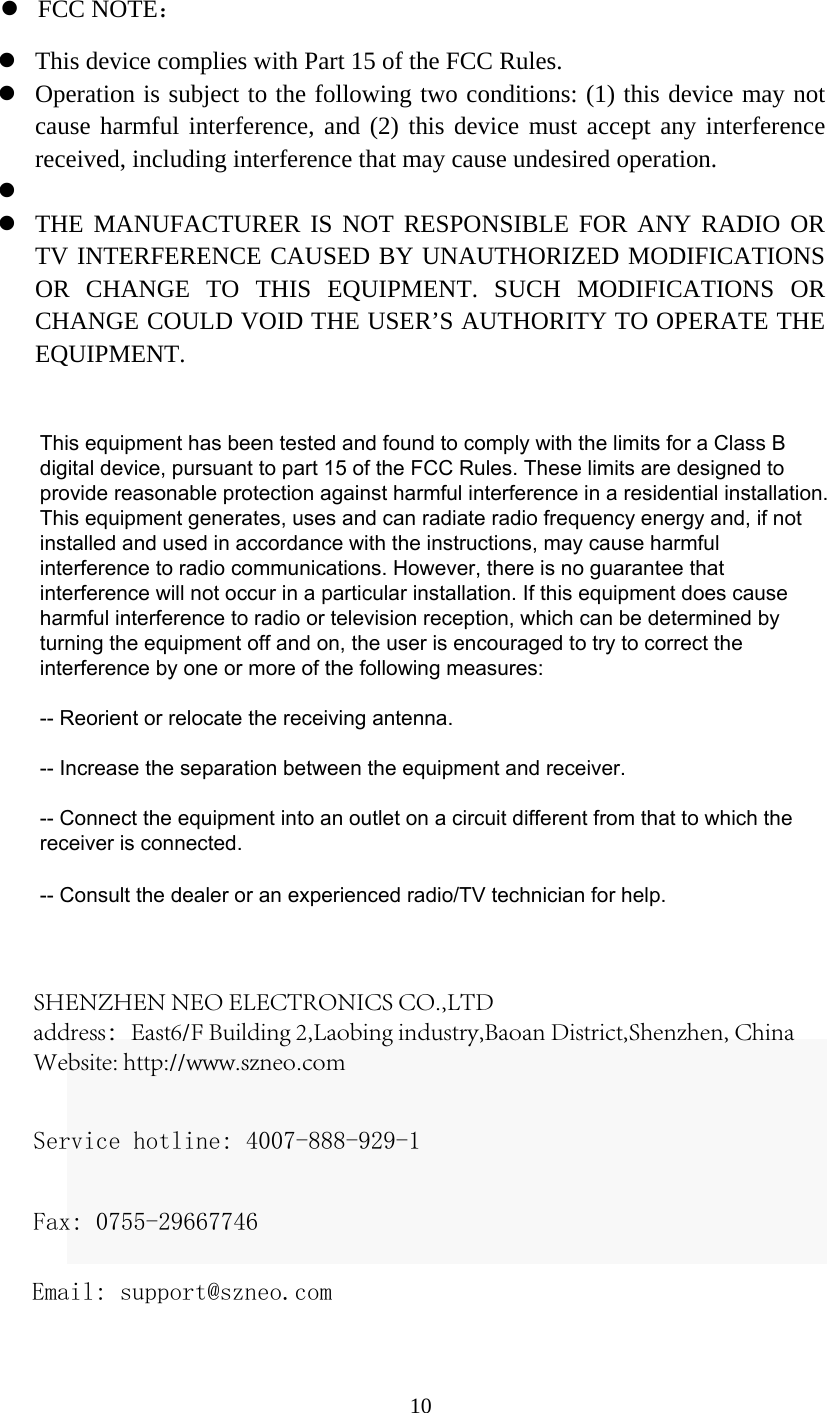
SHENZHEN NEO ELECTRONICS CO.,LTD Water sensor NAS WS01Z Manual User

User manual

  1            Installation instructions Water sensor Module Name: NAS-WS01Z  Thank you for your support to our products  Please carefully read the installation instructions before you used correctly  After reading, please safekeeping        Shenzhen Neo Electronic Co., LTD
2 Product introduction Spilled water detector is a through Z - wave of intelligent security of communication network equipment. In Z - wave network communication, excessive water detector can be any Z - wave and network control device to connect. Z - wave network using radio frequency, is decided by each country or region. In the overflow water detector and the main control device of communication, excessive water detector can only send information, can't receive messages. When spilled water detector is triggered, water detector sends a message to the main control equipment, the main control device can display the current state of the water detector, at the same time through the Z - wave devices linkage to other work. Water detector by the battery power, small volume, easy to install, when spilled water detector probe detected with water, water detector is triggered, namely so, reach the role of safety protection. Technical parametersPower supply: CR14250 X 1 Power consumption: 0.13 W Battery life (standby) : 37 months Standby current: 1.3 uA The maximum current 35 ma Wireless protocol: Z - wave Radio frequency:  908.42 MHzWireless distance: 50 m Working temperature: 0 to 40  ℃ Storage temperature: 0-60  ℃ Product size: (length X width X height) : 34 mm X 68 mm X 68 mm Technical information Easy installation, can use double glue and screwsBatteriesthrough alarm host can control other devicescan with any Z - wave network connectiontimely and accurately provide the location of the water and place, reduce economic lossescaused by water
  3  Product configuration                                                                                                                                                                                               Item listing  overflow detector                               1pcs  cell                                      1pcs     screw                                     3pcs  screw stopper                                 3pcs  installation instructions                               1pcs      Water detector stents The battery LED lights The code buttonscrew Screw stopper Induction tentacles The assembly mark Induction of contact The probe   interface
  4 Z - wave network added Spilled water detection by Z - wave master equipment add water detector to the Z - wave in the network。 1). Open water detectors, equipped with batteries, install the equipment in the main control network within the scope of the equipment. 2.) sets the main control device to add learning model (please refer to the specific master equipment operating instructions). 3) fast. Press the button three times to the code, LED lights flashing red light 5 times. 4). The main control device will detect water detector and add water detector to the Z - wave in the network. 5). Waiting for the master device configuration water detectors   Deleted from the Z - wave network sensor . Determine the power sensor has been connected. 2). Sets the main control device to remove learning model (please refer to the specific master equipment operating instructions). 3) fast. Press the button three times to the code, LED lights flashing red light 5 times. 4). Waiting for the main control equipment removed from Z - wave network sensor.
  5Installation steps  bracket installation  battery installation   will overflow water detectors installed on the bracket   installation sensing probe  Bracket installation Use screw and screw glue plug fixed bracket                  Battery installation                      Open water detectors                Install the battery               Good water detectors  Water will overflow detector installed on the bracket        Note: 1. Good water detectors, please note on the assembly. 2. Water will overflow detector installed on the bracket, please aim the induction tentacles and induction electric shock.
  6 Warm prompt   progr near the easy leakage of water, water will overflow detector probe head should be on the ground water easy to leak.   Avoid install the .lampblack, such as water vapor directly smoked the place。      avoid installed in the enclosure, such as alarm sound is not easy to place.   avoid install where water immersion.              please will overflow water detectors installed on the host network coverage range。     The LED display status 1. When the water detector is triggered, the LED flashing red light 5 times. 2. Water detector just equipped with batteries, LED lights flashing red light 5 times. 3. When the water detector is triggered, keep normally on LED lights. 4. The normal state, the state of LED lights to keep out                                                                                     Equipment linkage When spilled water detector is triggered, all of the equipment by its linkage will receive relevant reports. Spilled water detector by Z - wave main control device can control the Z_wave other devices within the network, such as linkage socket, alarm equipment, dimmer, and so on. Water detector support two sets of linkage: The first set of linkage can be allocated equipment state - when spilled water detector is triggered, based Settings command to be sent the linkage of the linkage device. A second group of linkage in Z - wave shown on the main control device or alarm host water detector current working condition.  Note: the water detector in linkage with other devices, they are direct communication through Z - wave network, alarm host or Z - wave master equipment was not involved. Restore the factory Settings Restore the factory Settings will be deleted and Z Z - Wave network - Wave master all information relating to the sensors in the device, and restore the sensor to the factory default Settings. 1. Open water detector host. 2. Ensure the sensor power supply. 3. Long press to code button for 10 seconds. 4. Loosen the button.
  7 Note: the factory default process, please do not power outages. Battery tips  The service life of the battery was designed for two years. The actual capacity in alarm host has showed. When the battery is too low, the phone APP will receive alarm sent by the host "battery is too low, please replace the battery" push information. Replace the battery, please cut off the linkage of the overflow water detectors and other equipment, so  as  not  to  cause  error  alarm  or  linkage  error  operation  of  the equipment. Note: Water detector equipped with batteries began to work, send information to the mainframe, triggering other devices linkage. Spilled water detector is used by batteries, battery, please according to the methods specified so as not to cause explosion. When handling the battery, please refer to the environment protection law.     Advanced configuration 1. Configuration delay shut down After the shutdown command is issued, this configuration parameter can be used to adjust the delay shut down automatically. This parameter can be furnished with a value of 0 to 65535, where 0 means immediately issued a shutdown command and 65535 refers to delay closing device after 65535 seconds  Function: open/close time. Parameter number: 1. Specification: 2 Byte The available Settings: 0-65535 (in seconds). The default Settings: 30 (in seconds)  2. The infrastructure level When spilled water detector is triggered, water detector will be sent contains a parameter value set command, the basis of the parameters of the receiver will follow infrastructure orders value; , for example, if a lamp module receives the basis set command, are included in the
  8basic setup command lamp module is determined by the parameters in the adjustable brightness levels.  Functions: basic Settings Parameter number: 2 Specifications: 1 byte The available Settings: 0, 1-99 or 255            0 - closed, alarm cancel or shut down power supply equipment            1-99 or 99 - open (binary switch equipment)                          Light  and  shade  levels  (multilevel  switch equipment) The default Settings: 99   The battery check command Users can also send BATTERY_GET command query to probe the battery status of overflowing. Once the water detector receives the command, it will reply BATTERY_REPORT command. If water detectors send BATTERY_LEVEL = 0 XFF command to Z - Wave master equipment, said water detector battery die, otherwise BATTERY_LEVEL value range of 0% to 100%。   Wake up the command class The water detector will maintain in the sleep state most of the time, reduce the water detector power consumption, extend battery life. The smallest wake up interval of 120 s; 16777215 s largest wake up of time (about 194 days); Allows each awaken the interval between the interval of 1 second, like 120121121...  The command class The sensor (water detector) support command class, as follows: * COMMAND_CLASS_ZWAVEPLUS_INFO (V2) * COMMAND_CLASS_VERSION (V2) * COMMAND_CLASS_MANUFACTURER_SPECIFIC (V2) * COMMAND_CLASS_DEVICE_RESET_LOCALLY (V1) * COMMAND_CLASS_POWERLEVEL (V1)  * COMMAND_CLASS_BATTERY(V1) * COMMAND_CLASS_ASSOCIATION(V2)
*COMMAND_CLASS_ASSOCIATION_GRP_INFO(V1)*COMMAND_CLASS_WAKE_UP(V2)**COMMAND_CLASS_SENSOR_BINARY(V2)COMMAND_CLASS_CONFIGURATION(V1)1. The product warranty will be provided by her electronic (shenzhen)co., LTD., shenzhen her electronic co., LTD is located in baoan district of shenzhen west township iron tsai road 44 veterans industrial city 2 6th floor on the east side, zip code 518102。 2. Customers buy our products all can enjoy a year of quality warrantyand lifetime after-sales service protection。 3. Warranty  service  is  only  applicable  to  equipment  the  originalpurchasers, the original purchasers to show the purchase documents shall prevail. The company based on the maintenance contract and effective implementation of quality assurance, adhere to the efficient service commitment, to provide timely stress of professional services。 4.The company is responsible for the maintenance can replace the damaged part of the original products, the client shall retain product damaged part and its accessories。 5.The company sold products, if quality problems because of damage, the company  responsible  for  repair  or  replacement,  and  afford  the transportation and installation costs。 6. Such as typhoon, flood, earthquake and other natural disasters causedby the damage of products to be outside the scope of the company's quality assurance。 7. Due  to  personal  misuse  or  artificial  damage,  such  as  violentcollisions, missing accessories, is beyond the scope of the company's quality assurance, maintenance, need to charge for。
10Service hotline: 4007-888-929-1 Fax: 0755-29667746 Email: support@szneo.com SHENZHEN NEO ELECTRONICS CO.,LTD address:East6/F Building 2,Laobing industry,Baoan District,Shenzhen, China  Website: http://www.szneo.com This device complies with Part 15 of the FCC Rules.Operation is subject to the following two conditions: (1) this device may notcause harmful interference, and (2) this device must accept any interferencereceived, including interference that may cause undesired operation. THE MANUFACTURER IS NOT RESPONSIBLE FOR ANY RADIO ORTV INTERFERENCE CAUSED BY UNAUTHORIZED MODIFICATIONSOR CHANGE TO THIS EQUIPMENT. SUCH MODIFICATIONS ORCHANGE COULD VOID THE USER’S AUTHORITY TO OPERATE THEEQUIPMENT.This equipment has been tested and found to comply with the limits for a Class B digital device, pursuant to part 15 of the FCC Rules. These limits are designed to provide reasonable protection against harmful interference in a residential installation. This equipment generates, uses and can radiate radio frequency energy and, if not installed and used in accordance with the instructions, may cause harmful interference to radio communications. However, there is no guarantee that interference will not occur in a particular installation. If this equipment does cause harmful interference to radio or television reception, which can be determined by turning the equipment off and on, the user is encouraged to try to correct the interference by one or more of the following measures: -- Reorient or relocate the receiving antenna. -- Increase the separation between the equipment and receiver. -- Connect the equipment into an outlet on a circuit different from that to which the receiver is connected. -- Consult the dealer or an experienced radio/TV technician for help.FCC NOTE:

Navigation menu