NETIS SYSTEMS 605GR2006M1 Wireless Broadband Router User Manual
NETIS SYSTEMS CO., LTD. Wireless Broadband Router
UserManual.wiki
>
NETIS SYSTEMS
>
605GR2006M1 User Manual
Manual
Navigation menu
Upload a User Manual
Namespaces
Wiki Guide
HTML
PDF
Info
Views
User Manual
Discussion / Help
Navigation
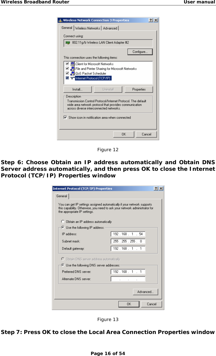
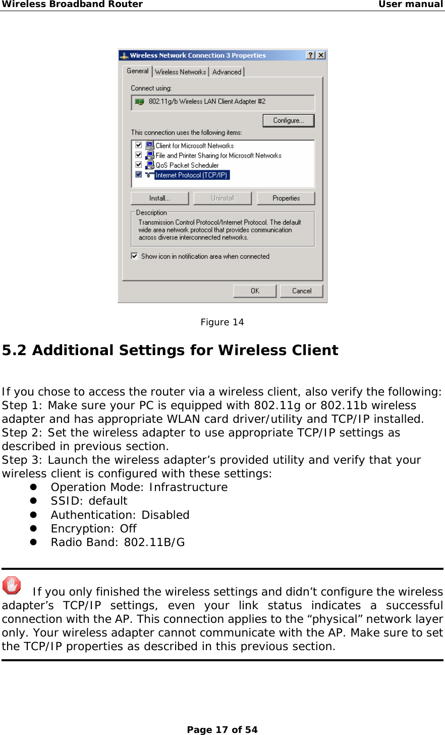
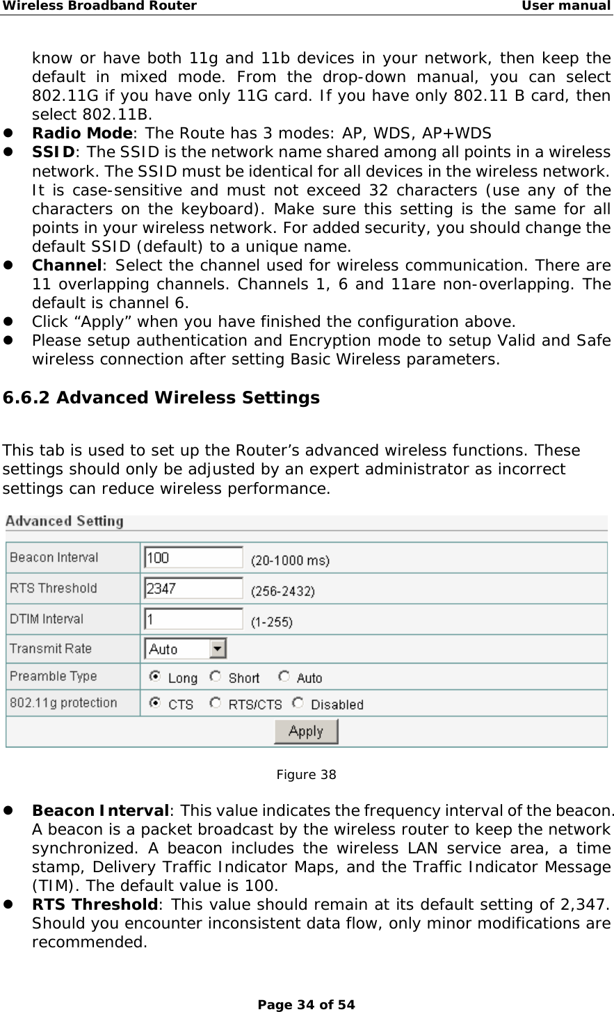
![Wireless Broadband Router User manual Page 33 of 54 If you change the private IP address and apply the changes, the PC from which you configure the router will lose the communication to the router. To reconnect, you will need to renew the IP address of the PC or change to an IP address compatible with the new LAN port IP address. 6.5.2 DHCP Info You can View all the pc which connect to the Wireless Router by DHCP here. Figure 36 6.6 Wireless Settings The Wireless Broadband Router implements Access Point capability, which connects wireless clients to a wired LAN. It allows wireless stations to access network resources and share the broadband Internet connection. 6.6.1 Basic Wireless Settings The basic settings for wireless networking are set on this screen. Figure 37 z Radio Band: The default setting is mixed mode [802.11B/G]. If you do not](https://usermanual.wiki/NETIS-SYSTEMS/605GR2006M1/User-Guide-660239-Page-33.png)