NETIS SYSTEMS DL4305R ADSL2 Modem Plus 300Mbps Wireless-N Router User Manual DL4305 EN Modem Router QIGx
NETIS SYSTEMS CO., LTD. ADSL2 Modem Plus 300Mbps Wireless-N Router DL4305 EN Modem Router QIGx
Users Manual

DL4305
ADSL2+ Modem Plus 300Mbps
Wireless-N Router
Quick Installation Guide

1
1. Hardware Installation
Step1:ConnecttheADSLLine.
Methodone:Plugoneendofthetwisted‐pairADSLcableinto
theADSLLINEportontherearpaneloftherouter,andinsert
theotherendintothewallsocket.Methodtwo:Youcanusea
separatesplitter.Theexternalsplitterhasthreeports:•
Line:Connecttothewalljack•Phone:Connecttothe
phonesets•Modem:ConnecttotheADSLLINEportof
therouter
Step2:ConnecttheEthernetcable.Attachoneendofanetwork
cabletoyourcomputer'sEthernetportoraregularhub/switchport,
andtheotherendtotheLANportontherouter.
Step3:PoweronthecomputersandLANdevices.
Step4:Attachthepoweradapter.Connectthepoweradaptertothe
powerconnectorontherearofthedeviceandplugintheadapterto
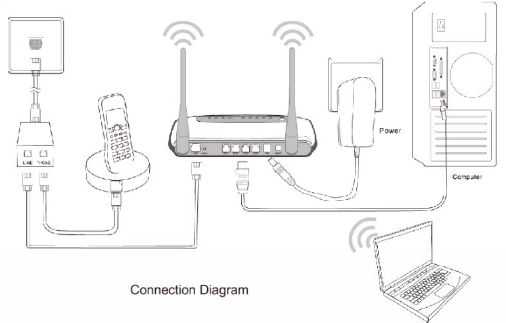
2
awalloutletorpowerextension.
Figure1

3
NameStatusIndication
OnPowerisonPWR
OffPowerisoff
FlashTheADSLnegotiationisinprogress
OnTheLINEportislinkedup.
ADSL
OffTheLINEportislinkeddown.
FlashDataisbeingtransferredovertheInternet.
OnAsuccessfulPPPconnectionhasbeenbuilt.
Internet
Off
ThereisnosuccessfulPPPconnectionorthe
RouterworksonBridgemode.
FlashThereiswirelessdatabeingtransmitted.
OnThewirelessfunctionisenabledbutnodatais
beingtransmitted.
WLAN
OffThewirelessfunctionisdisabled.
FlashDataisbeingtransferredoverthe1‐4(LAN)port.
On
Thereisasuccessfulconnectiononthe
corresponding1‐4(LAN)portbutnoactivity.
LAN(1‐4)
Off
Thereisnoconnectiononthecorresponding1‐4
(LAN)portortheconnectionisabnormal.
4
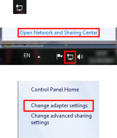
2. Configure PC
ForWindows7orWindowsVistaasbelow.
Step1:Click,thenselecttheOpenNetworkandSharing
Center.
Figure2
Step2:ClicktheChangeadaptersettings.
Figure3
Step3:ClickLocalAreaConnectionwiththerightbuttonofyour
mouse.ThenselectProperties.
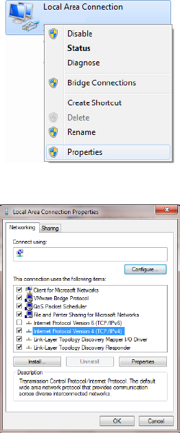
5
Figure4
Step4:Doubleclickthe“InternetProtocolVersion4(TCP/IPv4)”.
Figure5
6
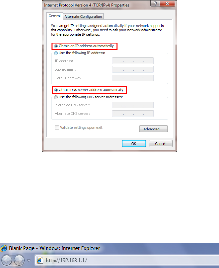
Step5:Selectthe“ObtainanIPaddressautomatically”asbelow.
Thenclick“OK”.
Figure6
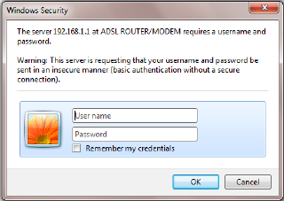
3. Login
StartyourwebbrowserandtypetheprivateIPaddressofthe
RouterintheURLfield:192.168.1.1.
Figure7
Then,enterthedefaultUserNameadminandthedefault
Passwordadmin
7
Figure8
AndthenclickOKtoaccesstotheWirelessModemManagement
Panelscreen.
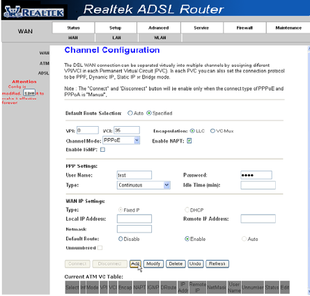
4. Modem Management
Thiswebpageprovidesyoutheconvenientandsimplestwayto
configureyourModemtoaccesstheinternet.
Firstly.Clickandgoto“Setup”‐>”WAN”,Pageisshowingbelow:
(wearetakingPPPoEforexample)
Secondly.EntertheVPIandVCIprovidedbyyourISPandselectthe
ChannelmodeasPPPoE
Third:EntertheFixedIPaddresswhichprovidedbyyourISPthen
click“Add”
8
Fourth:Click“Save”bottontomakeiteffetive.
Figure9
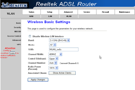
5. Wireless Network&Security
To connect to the Wireless AP, we should have the most basic
configuration of the router at first. In this section, you can set the
wireless network parameters required to access the AP of your WLAN
9
interface.
Go to Setup->WLAN->Basic page, you can configure the wireless
parameters.
Here you may enable or disable the wireless function. You can also
change the wireless parameters, such as Band, SSID, Channel Width,
Control Sideband, Channel Number and Radio Power.
Figure10
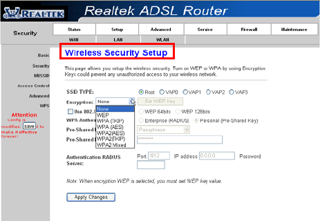
Step2:Go to Setup->WLAN->Security page, you can configure the
wireless security parameters.
Here you can choose the encryption method to prevent any
10
unauthorized access to your wireless network.
There are three most commonly used encryption method (a total of six
encryption support), including the WEP encryption, WPA-Personal,
WPA2-Personal, etc.
Click “Apply Changes” to make it effective
Figure11
Step3:Click“MyNetworkPlaces”withtherightbuttonofyour
mouse.Thenselect“Properties”.

11
Figure12
Step4:Click“WirelessNetworkConnection”withtherightbutton
ofyourmouse.Thenselect“ViewAvailableWirelessNetworks”.
Figure13
Step5:Doubleclickthewirelessnetworkyourproductprovided.
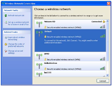
12
Figure14
Step6:Inputthekeyyoustettedbeforeifthewirelessnetworkyou
connectingtorequestspassword.
Certification
FCCCE
FCCStatement
Thisequipmenthasbeentestedandfoundtocomplywiththelimits
foraClassBdigitaldevice,pursuanttopart15oftheFCCRules.
Theselimitsaredesignedtopro‐videreasonableprotectionagainst
harmfulinterferenceinaresidentialinstallation.Thisequipment
generatesusesandcanradiateradiofrequencyenergyand,ifnot
in‐stalledandusedinaccordancewiththeinstructions,maycause
13
harmfulinterferencetoradiocommunications.However,thereisno
guaranteethatinterferencewillnotoccurinaparticularinstallation.
Ifthisequipmentdoescauseharmfulinterferencetoradioor
televisionreception,whichcanbedeterminedbyturningthe
equipmentoffandon,theuserisencouragedtotrytocorrectthe
interferencebyoneormoreofthefollowingmeasures:
•Reorientorrelocatethereceivingantenna.
•Increasetheseparationbetweentheequipmentandreceiver.
•Connecttheequipmentintoanoutletonacircuitdifferentfrom
thattowhichthereceiverisconnected.
•Consultthedealeroranexperiencedradio/TVtechnicianforhelp.
FCCRadiationExposureStatement
ThisequipmentcomplieswithFCCRFradiationexposurelimitsset
forthforanuncontrolledenvironment.Thistransmittermustnotbe
co‐locatedoroperatinginconjunctionwithanyotherantennaor
transmitter.Thisequipmentshouldbeinstalledandoperatedwitha
minimumdistanceof20centimetersbetweentheradiatorandyour
body.
ThisdevicecomplieswithPart15oftheFCCRules.Operationis
subjecttothefollowingtwoconditions:(1)thisdevicemaynot
causeharmfulinterference,and(2)thisdevicemustacceptany
interferencereceived,includinginterferencethatmaycause
undesiredoperation.
Caution!
Anychangesormodificationsnotexpresslyapprovedbytheparty
responsibleforcompliancecouldvoidtheuser'sauthoritytooperate
14
theequipment.
INFORMATIONTOBESUPPLIEDTOUSERS
Weconfirmthatthefollowinginformationwillsuppliedtotheusers
ofthisequipment.Thisinformationwillbeprovidedwiththeuser’s
manual.
FCCREQUIREMENTS
ThisequipmentcomplieswithPart68oftheFCCrulesandthe
requirementsadoptedbytheACTA.Ontheexteriorofthecabinetof
thisequipmentisalabelthatcontains,amongotherinformation,the
FCCRegistrationNumberandRingerEquivalenceNumber(REN)for
thisequipment.AproductidentifierintheformatUS:
SX5DL01BDL4305R.Ifrequested,thisnumbermustbeprovidedto
thetelephonecompany.
FCCcomplianttelephonecordandmodularplugisprovidedwiththis
equipment.Thisequipmentisdesignedtobeconnectedtothe
telephonenetworkorpremiseswiringusingacompatiblemodular
jackthatisPart68compliant.SeeInstallationInstructionsfordetails.
TheRENisusedtodeterminethequantityofdevicesthatmaybe
connectedtothetelephoneline.ExcessiveRENsonthetelephone
linemayresultinthedevicesnotringinginresponsetoanincoming
call.Typically,thesumofRENsshouldnotexceedfive(5.0).Tobe
certainofthenumberofdevicesthatmaybeconnectedtoaline(as
determinedbythetotalRENs)contactthelocaltelephonecompany.
Ifthisequipmentcausesharmtothetelephonenetwork,the
15
telephonecompanywillnotifyyouinadvancethattemporary
discontinuanceofservicemayberequired.Butifadvancenotice
isn’tpractical,thetelephonecompanywillnotifythecustomeras
soonaspossible.Also,youwillbeadvisedofyourrighttofilea
complaintwiththeFCCifyoubelieveitisnecessary.Thetelephone
companymaymakechangestoitsfacilities,equipment,operations
orproceduresthatcouldaffecttheoperationoftheequipment.If
thishappens,thetelephonecompanywillprovideadvancenoticeso
youcanmakethenecessarymodificationstomaintainuninterrupted
service.Fortechnicalsupport,contactNetisSystemsUSACorp.at
18541GaleAvenue,CityofIndustry,CA91748orcallTEL:626‐486‐
9208.Iftheequipmentiscausingharmtothetelephonenetwork,
thetelephonecompanymayrequestthatyoudisconnectthe
equipmentuntiltheproblemisresolved.