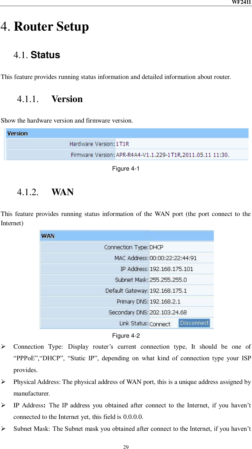
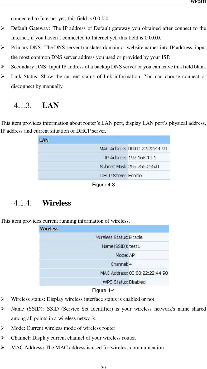
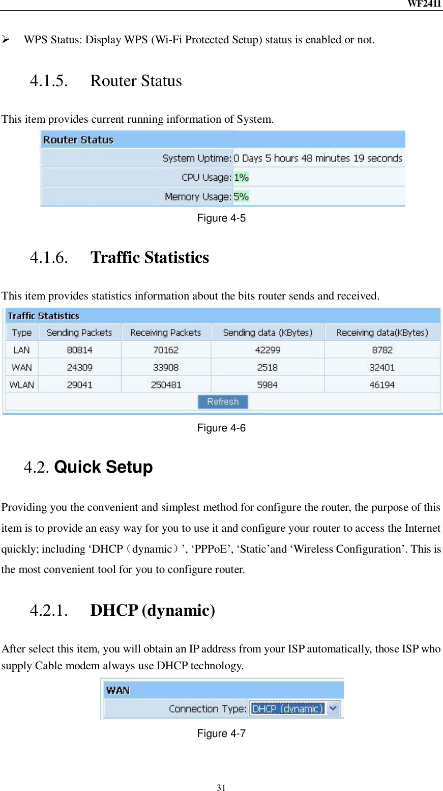
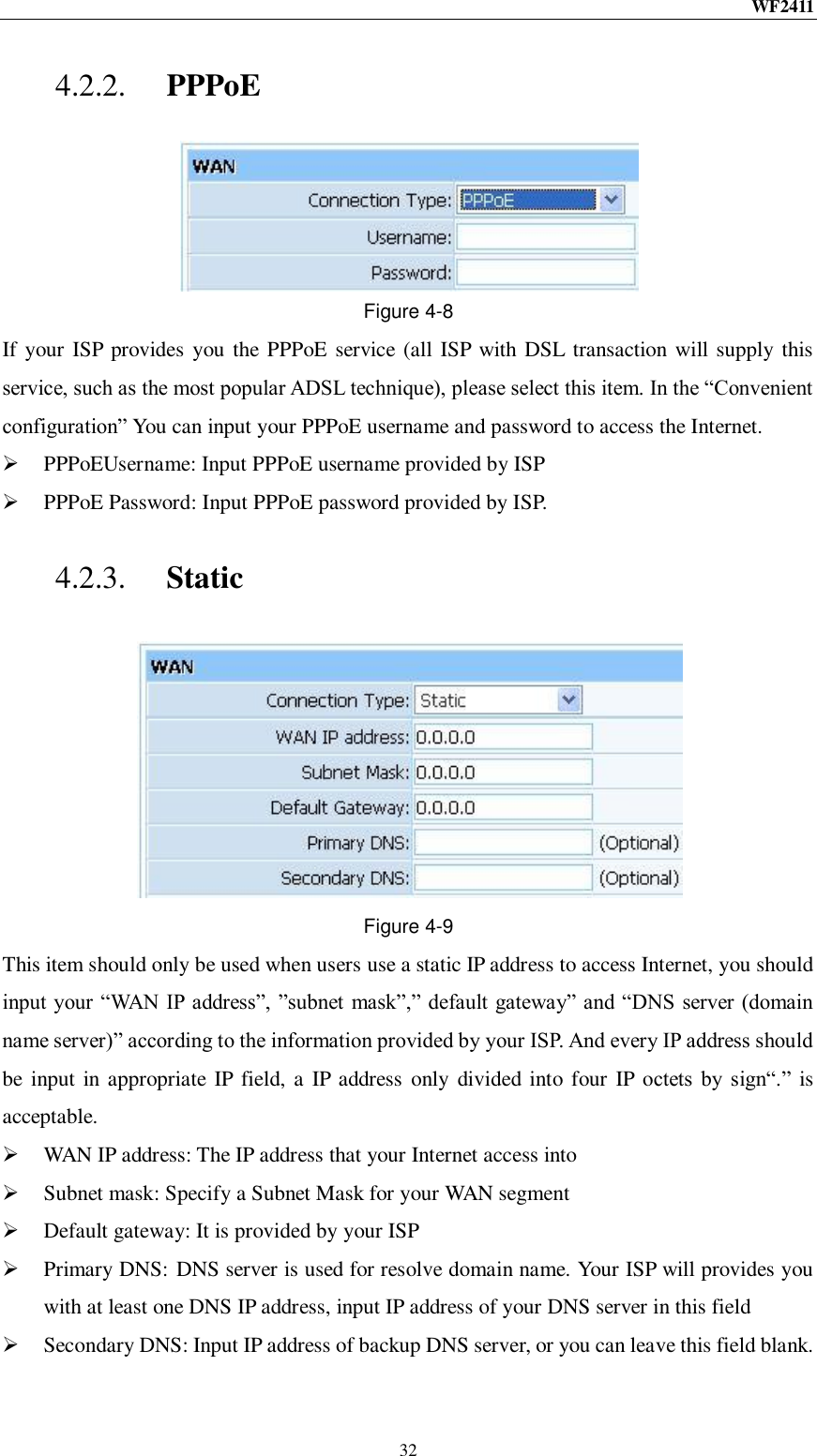
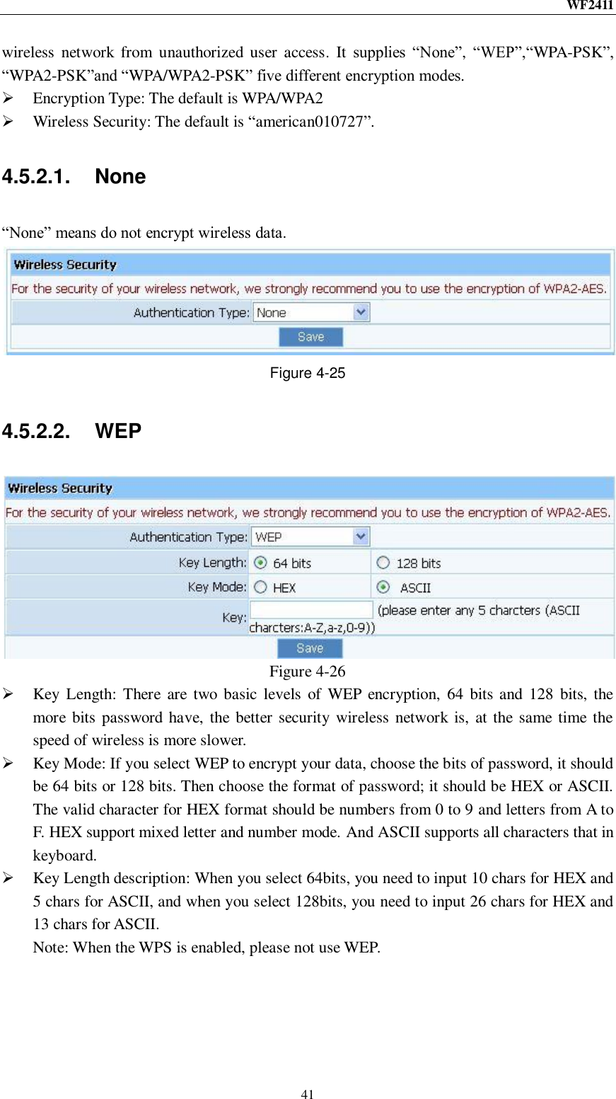
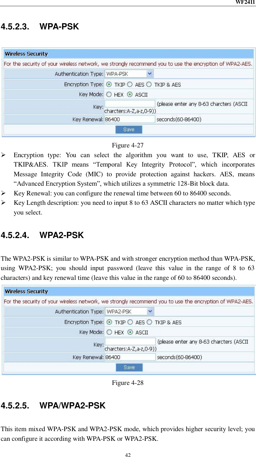
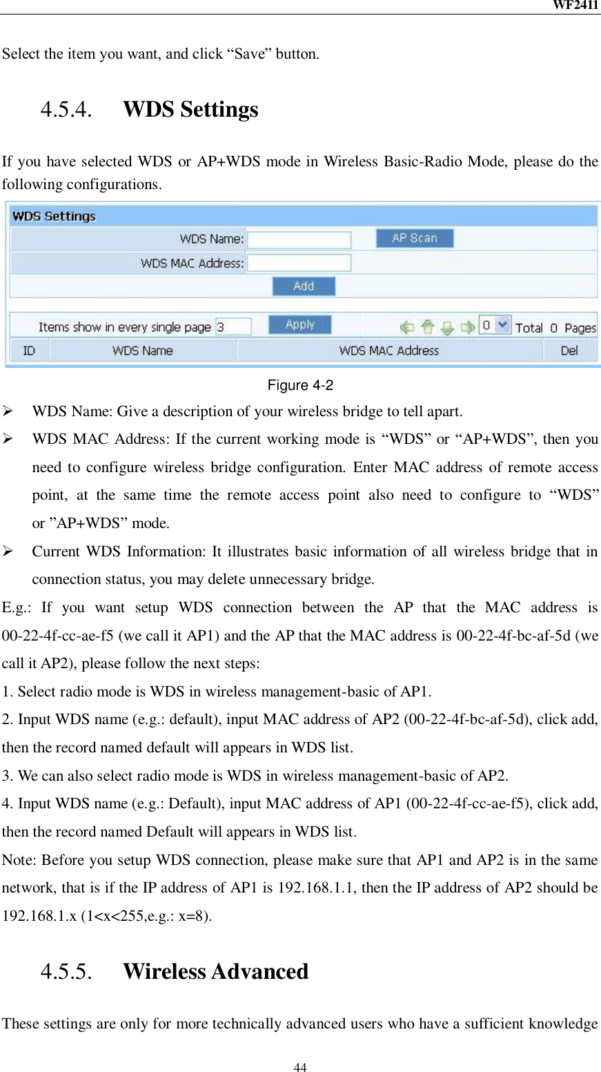
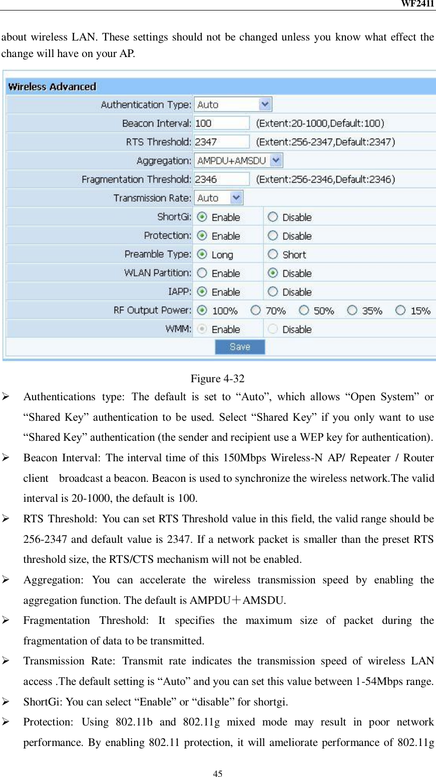
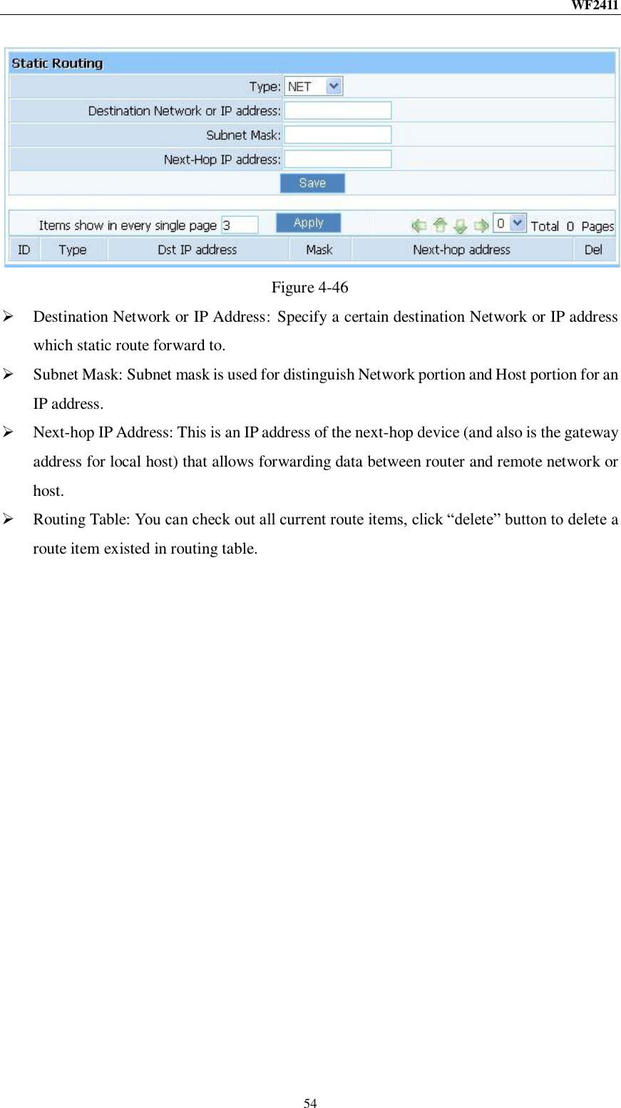
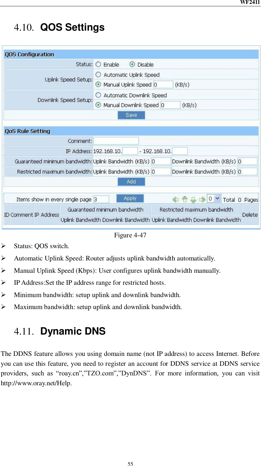
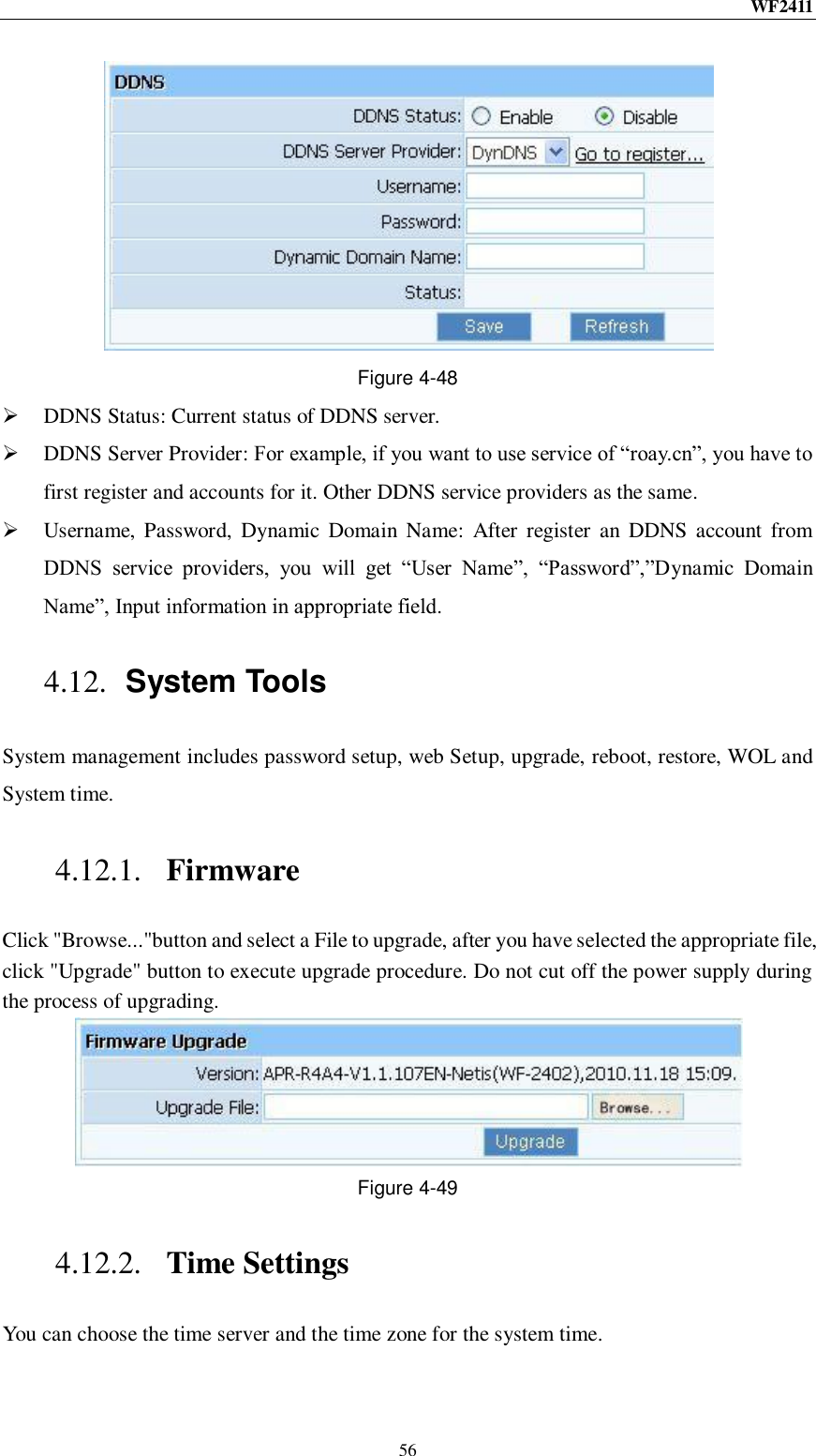
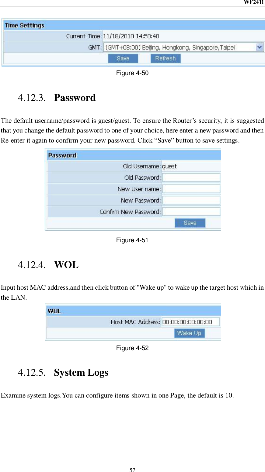
NETIS SYSTEMS WF2411R 150Mbps Wireless-N AP/Repeater/Router client User Manual
NETIS SYSTEMS CO., LTD. 150Mbps Wireless-N AP/Repeater/Router client
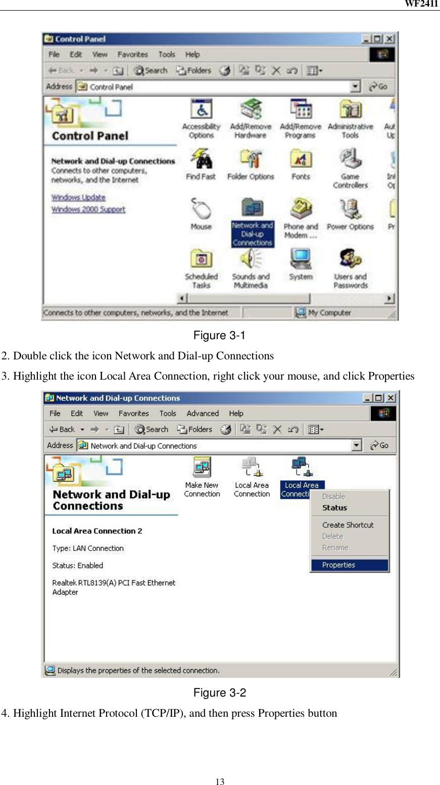
UserManual.wiki
>
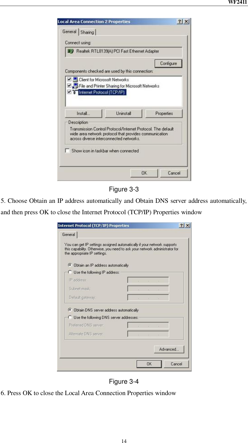
NETIS SYSTEMS
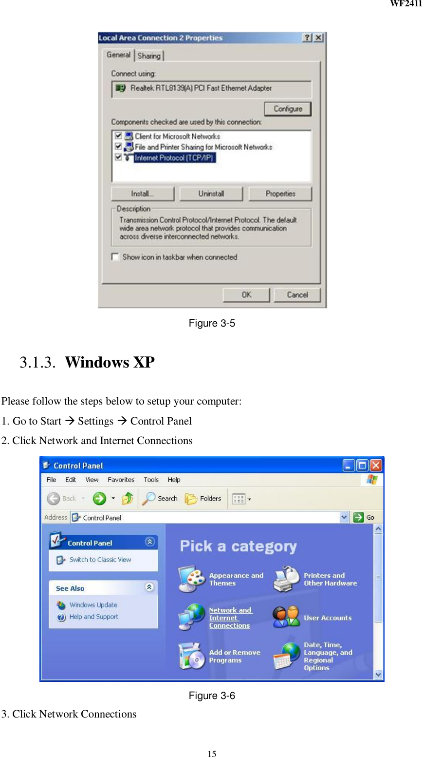
>
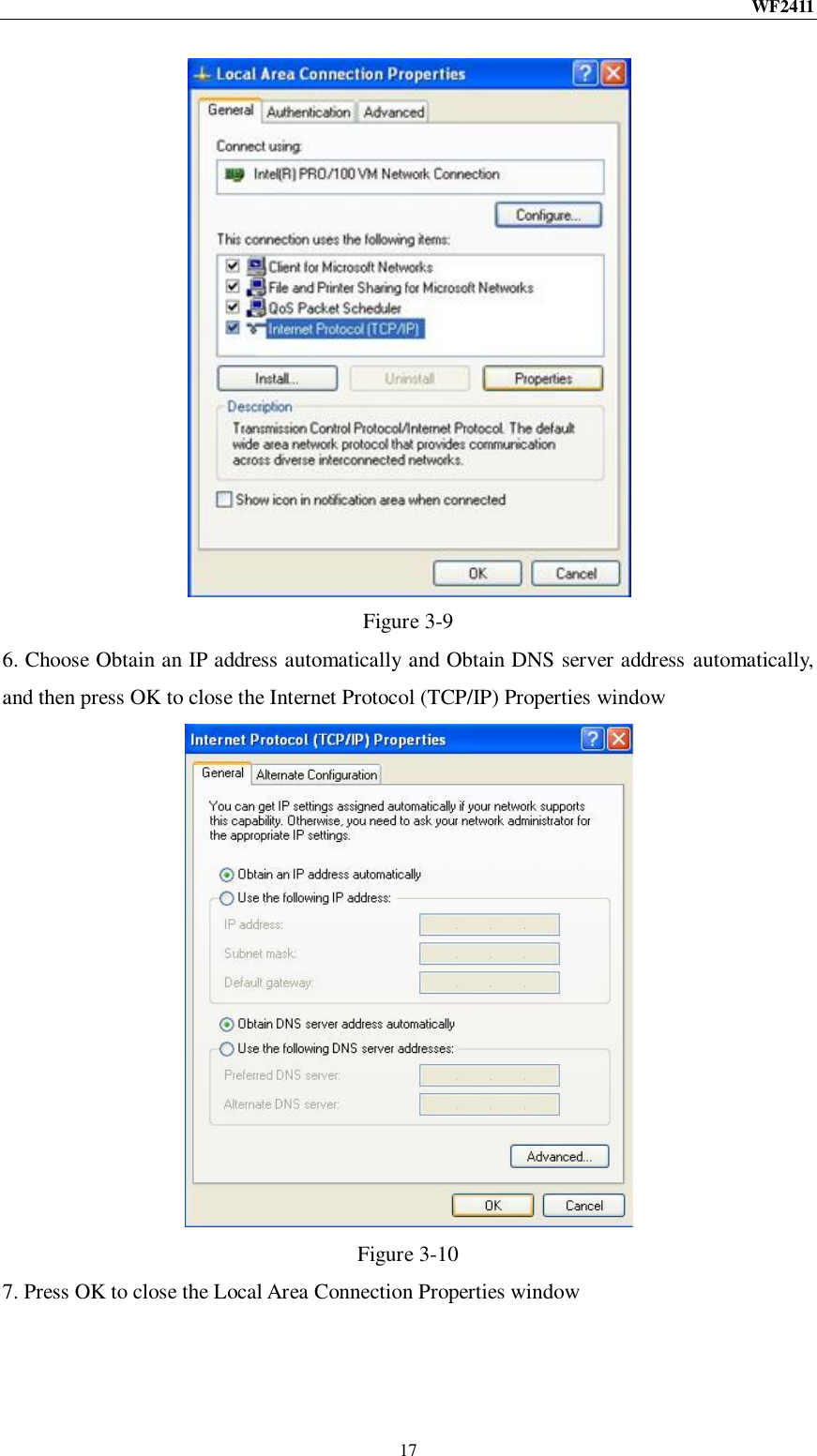
WF2411R User Manual
User manual
Navigation menu
Upload a User Manual
Namespaces
Wiki Guide
HTML
PDF
Info
Views
User Manual
Discussion / Help
Navigation