NETSCOUT Systems A5020 AirMagnet SmartEdge Sensor User Manual BARR
Fluke Networks/AirMagnet AirMagnet SmartEdge Sensor BARR
Users Manual

AirMagnet AM-5020-11AG
User Guide
Part Number: UG-AM-5020
© 2004 AirMagnet®, Inc. All rights reserved. 1

Table of Contents
Table of Contents............................................................................................................................ 2
Definitions and Terminology .......................................................................................................... 3
References....................................................................................................................................... 5
Introduction..................................................................................................................................... 6
Expert Analysis Functions Enabled by Sensor ............................................................................... 8
Enforce Security Policy ............................................................................................................ 8
Detect Wireless Intruders and Attacks...................................................................................... 8
Lock In Network Performance.................................................................................................. 9
Ensure Network Reliability....................................................................................................... 9
Centralizing System Management............................................................................................ 9
Enable Flexible Configuration and User Access ...................................................................... 9
Enable Graphics User Interface from Anywhere in the Network............................................. 9
Enable Remote Troubleshooting and Active Tools................................................................. 10
Low Overhead On Operational Network................................................................................ 10
AirMagnet Sensor Operation Modes ............................................................................................ 11
Configuration Mode................................................................................................................ 11
Analysis Mode ........................................................................................................................ 11
Active Control Mode .............................................................................................................. 12
Hardware Specifications............................................................................................................... 13
Mechanical.............................................................................................................................. 13
Environmental......................................................................................................................... 13
Power ...................................................................................................................................... 13
Radio Frequency..................................................................................................................... 14
Effective Data Rates ............................................................................................................... 15
Physical Interfaces .................................................................................................................. 15
Internal.................................................................................................................................... 15
Compliance ............................................................................................................................. 15
Sensor Powering Options.............................................................................................................. 16
AC Power................................................................................................................................ 16
Power-over-Ethernet (POE) Injector ...................................................................................... 16
Appendix A: FIPS-Required Features............................................................ 17
Use of TLS Protocol for Secure Communication................................................................... 17
Limited Logon Attempts......................................................................................................... 17
Length of Password Word....................................................................................................... 17
Automatic Self Checking and Module Integrity Checking..................................................... 17
Change of Shared Secret Key via Secure Communication..................................................... 18
Password Encrypted in FIPS-Approved Algorithms .............................................................. 18
Securing the Sensor with the Tampering-Proof Tape ............................................................. 18
Periodical Inspection of the Module for Evidence of Tampering........................................... 18
© 2004 AirMagnet®, Inc. All rights reserved. 2

Definitions and Terminology
802.3
802.11 a
802.11 b
802.11 g
802.11 e
802.1x
ACK Acknowledgement frame
AGC Automatic Gain Control
AID Association Identifier
BCC Binary Convolutional Code
BPSK Binary Phase Shift Keying
CF-End Contention-Free End
CFP Contention-Free Period
CF-Poll Contention-Free Poll
CTS Clear to Send
DA Destination Address
dB Decibels
DBPSK Differential Binary Phase Shift Keying
DCF Distributed Coordination Function
DIFS Distributed Interframe Space
DPSK Differential Phase Shift Keying
DQPSK Differential Quadrature Phase Shift Keying
DS Distribution System
DSSS Direct Sequence Spread Spectrum
EIFS Extended Interframe Space
ESS Extended Service Set
ETSI European Telecommunications Standards Institute
FCC Federal Communications Commission
FCS Frame Check Sequence
FFT Fast Fourier Transform
GFSK Gaussian Frequency Shift Key
GPS Global Positioning System
HR/DSSS High Rate Direct Sequence Spread Spectrum
I/Q Interphase/Quadrature
IAPP Inter-Access Point Protocol
ICI Interchip Interference
ICV Integrity Check Value
IEEE Institute of Electrical and Electronics Engineers
IPSEC VPN
IR Infrared ISI Intersymbol interference
ISM Industrial, Scientific, and Medical
LBT Listen Before Talk
L2TP VPN Layer 2 Tunneling Protocol VPN
© 2004 AirMagnet®, Inc. All rights reserved. 3

LEAP
LLC Logical Link Control
MIB Management Information Base
MIC Message Integrity Check
MKK Ministry of Telecommunications
MMACS Multimedia Mobile Access Communication System
MPDU MAC Protocol Data Unit
MSDU MAC Service Data Unit
NAV Network Allocation Vector
OFDM Orthogonal Frequency Domain Multiplexing
PBCC Packet Binary Convolutional Coding PC Point Coordinator
PCF Point Coordination Function
PEAP
PHY Physical Layer
PIFS Priority Interframe Space
PLCP Physical Layer Convergence Procedure
PMD Physical Medium Dependent
POE Power over Ethernet
PPDU PLCP Protocol Data Unit PFSF PLCP Signaling Field
PPTP VPN Point to Multiple Point Virtual Private Network
PS Poll Power Save Poll
QAM Quadrature Amplitude Modulation
QPSK Quadrature Phase Shift Keying
RA Receiver Address
RF Radio Frequency
RFID Radio Frequency ID
RSADSI RSA Data Security, Inc.
RTS Request to Send
SA Source Address
SFD Start of Frame Delimiter
SIFS Short Interframe Space
SNR Signal to Noise Ratio
SSH VPN
SSID Service Set Identity
STA Station
TA Transmitter Address
TBT Target Beacon Transmission Time
TIM Traffic Indication Map
TKIP
TLS
TSF Timer Synchronization Factor
TTLS
TU Time Units
WEP
WLAN Wireless LAN
WPA
© 2004 AirMagnet®, Inc. All rights reserved. 4

Introduction
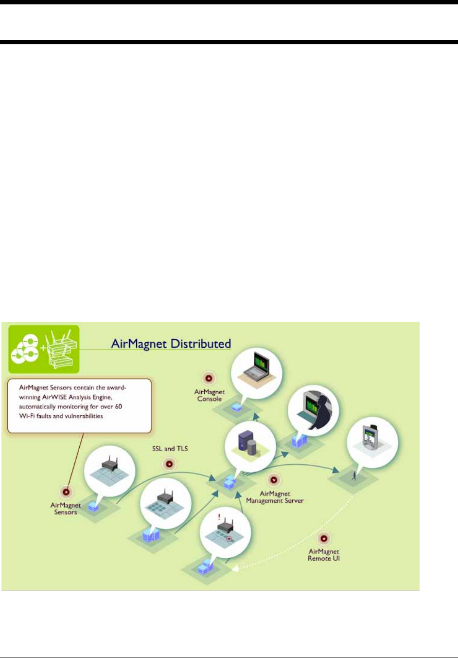
The AirMagnet AM-5020-11AG Sensor provides 24x7 remote monitoring and troubleshooting of
802.11 wireless networks. Sensors are deployed near clusters of access points, and provide
security assessment, performance monitoring, network fault detection and remote
troubleshooting functions. Management staff can easily monitor the security measures in use on
every station and access point device to insure compliance with established policies, and also
automatically scan for dozens of wireless network attacks.
These analysis functions can be monitored and controlled from both centralized and distributed
operations centers. These centers can be located in the building, on the campus, or anywhere in
the world without requiring high travel costs or excessive delay of sending IT expert staff to
remote locations.
Figure 1 shows a complete network including the AM-5020-11AG AirMagnet Sensor.
Companion software functions available for the complete AirMagnet Enterprise system include
the following:
AirMagnet Enterprise Server – provides the dynamic operations control function to the entire
network of bound sensors including sensor activation/deactivation, upgrade of sensor software,
and collection of alerts, data, and statistics for all stations and access points within wireless
segments monitored by the sensors.
Figure 1: WLAN Network with AM-5020-11AG AirMagnet SmartEdge Sensors Installed
AirMagnet Enterprise Console – provides the graphical user interface into the server from any
© 2004 AirMagnet®, Inc. All rights reserved. 6

location in the enterprise wide network.
AirMagnet Enterprise Remote User Interface – provides the graphical user interface into any
individual sensor from any location in the enterprise wide network.
Enterprise Reporter – manages and administers a SQL database of all collected alarms,
monitored traffic, and RF signal/noise information. Also provides a broad set of detailed reports
and trend summaries of key data. Using Reporter the administrator is able to conduct both short-
term and long-term trend analysis and also conduct forward looking capacity planning and
topology reconfiguration planning for the entire wireless network.
© 2004 AirMagnet®, Inc. All rights reserved. 7

Expert Analysis Functions Enabled by Sensor
The intelligent sensor provides around-the-clock coverage of the entire wireless environment
including all 802.11a, 802.11b, and 802.11g channels and infrastructure. Each individual sensor
is armed with the patent-pending AirWISE Analytical Engine that, in real time, monitors and
analyzes the security, performance, and reliability of the wireless network. The sensor enables
the following categories of expert analysis functions. See ANNEX B for a detailed and full
listing of expert analysis functions.
Enforce Security Policy
New security protocols are continually appearing that close the security gap between WLANs
and their wired counterparts. Nevertheless ensuring that all users and stations comply with these
security measures continues to grow as the major issue for wireless networks. AirMagnet Sensors
address this gap by auditing and validating the security of every Wi-Fi device in the network,
providing managers with an easy process to insure all users employ the appropriate level of
security. Supported protocols include:
• wep
• leap
• peap
• tkip
• mic
• 802.1x
• ttls
• tls
• wpa
• pptp vpn
• l2tp vpn
• ssh vpn
• ipsec vpn
Detect Wireless Intruders and Attacks
As Wi-Fi has grown, so have the number and sophistication of wireless attacks. AirMagnet
Sensors are engineered specifically to counter these threats - scanning the environment for
Rogue APs and War-Drivers, Spoofed MAC Addresses, and a host of Denial of Service Attacks
unique to Wi-Fi. Sensors send encrypted alarms in real time in response to an attack, allowing
the staff to respond before network operations are negatively impacted.
© 2004 AirMagnet®, Inc. All rights reserved. 8

Lock In Network Performance
Radio Frequency transmissions are inherently susceptible to environmental factors such as
physical obstructions and radio interference from a variety of sources. If not identified and
managed, these factors can lead to unacceptable performance for the end-user. To address this
challenge, AirMagnet Sensors constantly monitor and generate alarms on over 20 key indicators
of network health, allowing IT administrators to take a proactive approach toward the
maintenance of the network.
Ensure Network Reliability
WLANs must both have predictable performance and be highly reliable before being considered
industrial grade. The AirMagnet Enterprise System addresses this need with a suite of alarms and
diagnostics that detect network faults and configuration errors that can lead to outages in the
network. These diagnostics are complemented by active utilities to pin down the sources of
connectivity problems in the network.
Centralizing System Management
The AirMagnet Management Server receives information from every AirMagnet Sensor and
provides a centralized SQL database of all network data and alarms. SNMP traps allow for
seamless integration with leading management consoles such as HP Open View and CA
UniCenter. All sensor-to-server traffic is secured via SSL and TLS insuring management
information remains secure while transiting corporate firewalls and VPNs.
Enable Flexible Configuration and User Access
The Management Server maintains configurations for every Sensor in the System, allowing IT
Personnel to tune sensor thresholds appropriately for each location. Additionally, AirMagnet
Enterprise supports three unique administrative user levels, insuring that the users access only
the level of information appropriate for their role and level of responsibility.
Enable Graphics User Interface from Anywhere in the Network
The AirMagnet Management Console provides the User Interface to the AirMagnet Enterprise
System. From the Management Console, Users can view alarms and WLAN health by Campus,
Building, Floor, or by individual Sensor. Consoles can be run securely whether in a NOC, or
remotely on a laptop – keeping administrators connected to the information they need, regardless
of their location.
© 2004 AirMagnet®, Inc. All rights reserved. 9

Enable Remote Troubleshooting and Active Tools
Using the Remote UI built into the AirMagnet Management Console, Users can leverage a
growing collection of active troubleshooting tools to pinpoint problems in the network. These
tools allow the User to remotely test throughput on a particular AP, diagnose connection
problems, and perform Layer 3dDebugging and end-to-end provisioning. Administrators can
view low level data on every channel and device in the area, alarms, real-time local statistics, and
even packet decodes. Such remote capability greatly reduces the need to dispatch resources
when troubleshooting the WLAN.
Low Overhead On Operational Network
Most remote monitoring systems simply capture wireless packets and resend them to a remote
site for processing, needlessly consuming valuable bandwidth. AirMagnet Sensors, conversely
process locally, sending real-time alarms only when thresholds are reached. Trending data is
saved on the sensor, and securely sent at regular intervals to the Management Server, minimizing
operational load on the network and servers.
© 2004 AirMagnet®, Inc. All rights reserved. 10

AirMagnet Sensor Operation Modes
The Sensor has three operational modes, configuration mode, analysis mode, and active control
mode.
Configuration Mode
The Airmagnet Sensor can be configured both with a serial command line interface (CLI) and
secure HTTPS communications with a remote browser. Key parameters that need to be
configured prior to placing the sensor online include provisioning of the unit’s network
addressing, the server’s network addressing, and the secret key needed for connection to the
server and for administrator logon-override functions. Once the unit is configured it is placed on
the live network and powered up. The sensor can be powered either by an AC-to-DC power
brick or Power-over-Ethernet using an AirMagnet in-line power injector.
After configuration the unit boots up, connects to the server, and receives any additional
configuration parameters. If the administrator has upgraded the sensor software on the server to
a new release, the sensor automatically downloads the software into memory and then writes it to
flash.
Analysis Mode
The majority of the time the sensor is in the analysis mode. The unit scans all configured
channels, measures signal and noise, gathers statistics on management and data traffic, analyzes
security mis-configurations and performance problems, and searches for issues such as rogue
access points and denial of service attacks.
All of the analyzed data is recorded in memory and is reported back to the management server
periodically. The reporting period for accumulated data is configurable. Whenever an event
occurs that generates an alert, such as a security mis-configuration, the alert is sent immediately
to the server.
The administrator can view the consolidated status of the entire network, a subset of the network,
or the specific set monitored and analyzed by an individual sensor. The AirMagnet Enterprise
Console tool is used to view this information collected on the server.
The Analysis mode can be administered from anywhere within the global enterprise network.
© 2004 AirMagnet®, Inc. All rights reserved. 11

Active Control Mode
In active mode the sensor can drill down to an individual access point or station, and diagnose
connection and provisioning problems. Using the Remote User Interface function within the
Console program, the administrator can see a real time display of all scanning and analysis
functions performed by the sensor. He can zero in on channels, individual access points, or
individual stations. He can plot real time displays of all monitored information such as signal,
noise, traffic, and errors. He can also do packet decodes and statistical charting.
The Active Control mode can be administered from anywhere within the global enterprise
network.
© 2004 AirMagnet®, Inc. All rights reserved. 12

Hardware Specifications
The AirMagnet AM-5020-11AG sensor is a robust hardware monitoring analysis device that can
be installed on a shelf, on the wall, or in a ceiling. It can be powered by AC power, or by -48V
Power over Ethernet. The detailed technical specifications are as follows.
Mechanical
Enclosure
Metallic chassis
Dimensions 6.693 in. (17.0 cm) wide; 8.267 in. (21.0 cm) deep
Mounting options
Flat on shelf
Plastic stand for shelf vertical configuration
Wall hanging via dual screw holder at back of housing, or
Using AirMagnet mounting kit for wall and ceiling
Weight 32 oz (909g)
LEDs
Power status
WLAN (5 GHz/2.4 GHz) status
10/100 Base T status
Link status
Switches
Reset switch
RF connectors
Reverse polarity TNC – female
Environmental
Temperature
32º to 131ºF (0º to 55ºC)
Humidity
5 to 95% humidity (non-condensing)
Power
Power supply options
External power adapter w/ 12VDC/1A
Power over Ethernet (POE)
Power injector
48VDC +/- 10% and 400mA
Max distance between power injector and sensor is 100 meters
Power injector
© 2004 AirMagnet®, Inc. All rights reserved. 13

Coaxial Barrel connector female port
RJ45 DATA IN port (unpowered)
RJ45 DATA OUT port (-48VDC)
Power consumption
9.2 watts RMS
Radio Frequency
Bands 2.4 GHz Band: 802.11b/g
5.25-5.35 GHz Band: 802.11a
5.75 GHz: 802.11a
Country Frequency plans
All worldwide frequency plans (See ANNEX A for detail)
Antenna
Omni-directional
Dual antenna
Receive Sensitivity (Typical @ the antenna ports)
802.11a:
-84dBm @ 6Mbps -77dBm @ 18Mbps -70dBm @ 48Mbps
-82dBm @ 9Mbps -75dBm @ 24Mbps -68dBm @ 54Mbps
-79dBm @ 12Mbps -73dBm @ 36Mbps
802.11b/g:
-91dBm @ 1Mbps -84dBm @ 6Mbps -75dBm @ 24Mbp
-90dBm @ 2Mbps -82dBm @ 9Mbps -73dBm @ 36Mbps
-89dBm @ 5.5Mbps -79dBm @ 12Mbps -70dBm @ 48Mbps
-87dBm @ 11Mbps -77dBm @ 18Mbps -68dBm @ 54Mbps
Transmit Output Power (Typical @ the antenna ports)
802.11a:
18dBm+/-2 @6-24Mbps 15dBm+/-2 @54Mbps
17dBm+/-2 @36Mbps
16dBm+/-2 @48Mbps
802.11g:
20dBm +/-2dBm @ 6~24Mbps 17dBm +/-2dBm @ 48 Mbps
19dBm +/-2dBm @ 36 Mbps 15dBm +/-2dBm @ 54 Mbps
802.11b:
20dBm +/-2dBm for all rates
© 2004 AirMagnet®, Inc. All rights reserved. 14

Effective Data Rates
802.11a
6, 9, 12, 18, 24, 36, 48, 54
802.11g
6, 9, 12, 18, 24, 36, 48 & 54Mbps
802.11b
1, 2, 5.5, 11Mbps
Physical Interfaces
Network port
RJ45 Ethernet with POE powering option
10/100 Base T
Serial Port
RS232 DB9
115,200 bps; 8 data bits; no parity; 1 stop bit; no flow control
Internal
Processor
IDT RC32438 200Mhz
Memory
64 Mbytes RAM
8 Mbytes FLASH
Radio
Dual radio – 802.11 a & b/g
Atheros MAC and PHY
Compliance
FCC Part 15C
CE 0560
EN60950 (equivalent UL ETSI 300/328)
IC (Canadian Radio Regulations)
Japan Equipment Radio Regulations
© 2004 AirMagnet®, Inc. All rights reserved. 15
Sensor Powering Options
AC Power
The unit can be powered with AC power. An AC-to-DC power supply converts from AC to 12V
DC.
Power-over-Ethernet (POE) Injector
The unit can also be powered with Power over Ethernet (POE). In this configuration no AC
power is required near the Sensor. This is ideal for applications that are not near normal sources
of power, such as above a false ceiling or high on a wall.
AirMagnet POE uses existing CAT 5 cable to carry –48V DC power to the sensor.
Note: AirMagnet’s power over Ethernet solution is compatible with AirMagnet power injectors.
A future version will be compatible with the emerging IEEE 802.3af POE standard. No plans
exist for compatibility with Cisco’s proprietary pre-802.3af solution.
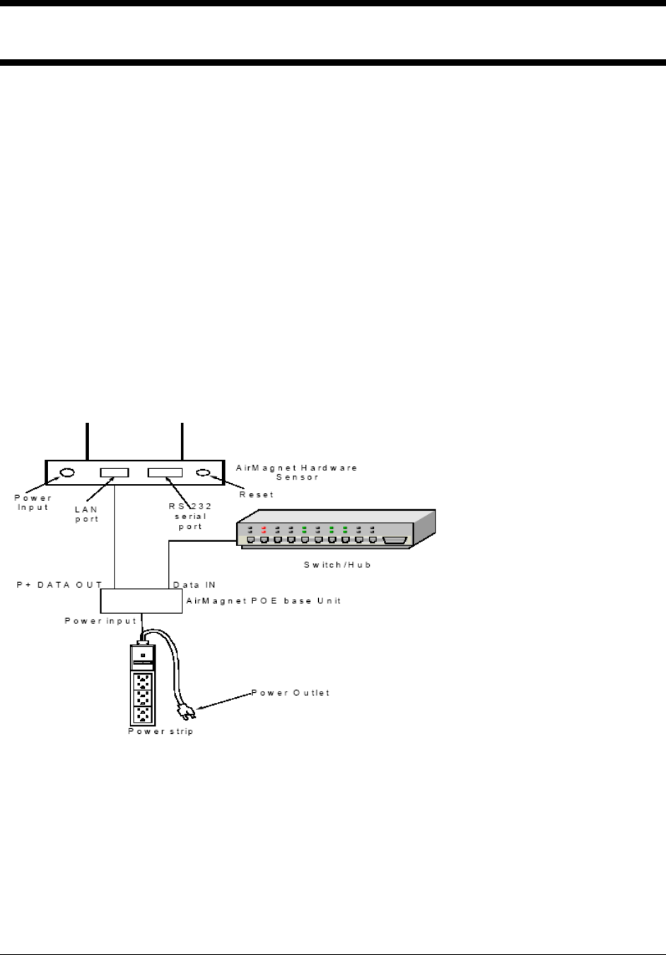
Figure 2: AirMagnet POE Injector
The POE injector has three ports and a single LED. One port accepts a coaxial barrel connector
that distributes 48V DC power. One port is RJ45 and attaches to the incoming Ethernet cable
which has no power. One port is RF45 and attaches to the outgoing Ethernet cable which has –
48V power.
© 2004 AirMagnet®, Inc. All rights reserved. 16
Appendix A: FIPS-Required Features
The features described here are required by the Federal Information Processing Standards (FIPS).
Use of TLS Protocol for Secure Communication
FIPS requires the use of TLS protocol for secure communication. Otherwise, there would be no
communication among the AirMagnet SmartEdge Sensor, the AirMagnet Enterprise Console,
and the AirMagnet Enterprise Server.
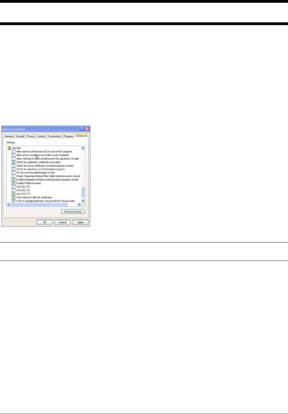
To comply with the FIPS requirement, you must configure your Internet Explorer by using these
commands: Start>Internet Explorer>Tools>Internet Options...>Advanced>Security>Use
TLS 1.0. See Figure 6.
Figure 6: Configuring Security Settings
As shown in Figure 6, the user must check Use TLS 1.0 in order for the Sensor to communicate
with the AirMagnet Enterprise Server using the FIPS-mode.
Limited Logon Attempts
The user is allowed a maximum of 3 logon attempts per minute.
Length of Password Word
The password used to access the AirMagnet Enterprise system must be between 6 and 36
characters in length. All passwords must include upper- and lower-case letters, and at least one (1)
numeric character and one (1) punctuation character.
Automatic Self Checking and Module Integrity Checking
AirMagnet SmartEdge Sensor will automatically perform self checking and module integrity
checking upon the start or reboot of the AirMagnet Enterprise system to ensure the system
security and integrity.
© 2004 AirMagnet®, Inc. All rights reserved. 17

If your Command Line Interface is open, the following commands will be displayed on the
screen:
Start FIPS Self Test for Encrypted Algorithm...
Passed.
AmWebserver Module Integrity Checking...
Passed.
AmConfig Module Integrity Checking...
Passed.
AmMonitor Module Integrity Checking...
Passed.
Checking Done.
If an error occurs during the self checking, then the AirMagnet SmartEdge Sensor will enter an
error state, in which all communication among the Sensor, Server, and Console will be disabled
since NO secure communication is allowed in an error state. The Sensor will keep generating the
same error message. If this occurs, contact AirMagnet Technical Support for assistance.
Change of Shared Secret Key via Secure Communication
FIPS does NOT allow the change of the shared secret key through Telnet due to the lack of
encryption in the Telnet communication protocol. If, for some reason, the user needs to change
the shared secret key, it can be done either through the serial port or a browser interface.
Password Encrypted in FIPS-Approved Algorithms
All passwords used to access the Sensor will be encrypted using a FIPS-approved algorithm and
saved in a file. Passwords entered using a Web browser and the TLS protocol and those entered
using the serial port meet the requirement.
Securing the Sensor with the Tampering-Proof Tape
To prevent your AirMagnet SmartEdge Sensor from tampering that may jeopardize the security
and integrity of your corporate network, use the supplied tamper-proof tape to cover the screws
at the bottom of each Sensor. At least two tapes should be applied, diagonally.
Periodical Inspection of the Module for Evidence of Tampering
Tamper evidence includes unexpected scratches on the cover and damage to the tamper-proof
tape surrounding the module. If tampering is suspected, zeroize the cryptographic keys and
shared key using the zeroize command. Then remove the module from service and contact
AirMagnet Technical Support for assistance.
When operating the Sensor in FIPS-approved mode, administrators must take precaution to
avoid disclosure of sensitive authentication data, including the shared secret key and passwords.
Follow all of the guidance in this section to ensure that the module is installed and operated in a
© 2004 AirMagnet®, Inc. All rights reserved. 18

secure manner.
Federal Communication Commission Interference Statement
This equipment has been tested and found to comply with the limits for a Class B digital
device, pursuant to Part 15 of the FCC Rules. These limits are designed to provide
reasonable protection against harmful interference in a residential installation. This
equipment generates, uses and can radiate radio frequency energy and, if not installed
and used in accordance with the instructions, may cause harmful interference to radio
communications. However, there is no guarantee that interference will not occur in a
particular installation. If this equipment does cause harmful interference to radio or
television reception, which can be determined by turning the equipment off and on, the
user is encouraged to try to correct the interference by one of the following measures:
- Reorient or relocate the receiving antenna.
- Increase the separation between the equipment and receiver.
- Connect the equipment into an outlet on a circuit different from that
to which the receiver is connected.
- Consult the dealer or an experienced radio/TV technician for help.
This device complies with Part 15 of the FCC Rules. Operation is subject to the
following two conditions: (1) This device may not cause harmful interference, and (2)
this device must accept any interference received, including interference that may
cause undesired operation.
FCC Caution: Any changes or modifications not expressly approved by the party
responsible for compliance could void the user's authority to operate this equipment.
IMPORTANT NOTE:
FCC Radiation Exposure Statement:
This equipment complies with FCC radiation exposure limits set forth for an uncontrolled
environment. This equipment should be installed and operated with minimum distance 20cm
between the radiator & your body.
If this device is going to be operated in 5.15 ~ 5.25GHz frequency range, then it is
restricted in indoor environment only.
This transmitter must not be co-located or operating in conjunction with any other antenna or
transmitter.
AirMagnet declares that A5020 ( FCC ID: RD7-A5020 ) is limited in CH1~CH11 for
2.4 GHz by specified firmware controlled in U.S.A.
© 2004 AirMagnet®, Inc. All rights reserved. 19

IC statement
Operation is subject to the following two conditions:
1) This device may not cause interference and
2) This device must accept any interference, including interference that may cause
undesired operation of the device.
To prevent radio interference to the licensed service (i.e. co-channel Mobile Satellite
systems) this device is intended to be operated indoors and away from windows to provide
maximum shielding. Equipment (or its transmit antenna) that is installed outdoors is subject
to licensing.
Because high power radars are allocated as primary users (meaning they have priority) in
5250-5350 MHz, these radars could cause interference and/or damage to license exempt
LAN devices.
This device has been designed to operate with an antenna having a maximum gain of 8 dBi.
Antenna having a higher gain is strictly prohibited per regulations of Industry Canada. The
required antenna impedance is 50 ohms.
© 2004 AirMagnet®, Inc. All rights reserved. 20