NETSCOUT Systems A520X AirMagnet A5200 Sensor / AirMagnet A5205 Sensor User Manual A5200 Sensor User Guide
Fluke Networks/AirMagnet AirMagnet A5200 Sensor / AirMagnet A5205 Sensor A5200 Sensor User Guide
Contents
- 1. Manual A5200
- 2. Manual A5205
Manual A5200

AirMagnet A5200 Sensor
User Guide
®
A5200 Sensor User Guide.book Page 1 Thursday, January 15, 2009 2:00 PM
© 2009 AirMagnet®, Inc. All rights reserved.
AirMagnet® A5200 Sensor User Guide.
This User Guide is furnished under license and may be used or copied
only in accordance with the terms specified in the license. The content of
this document is furnished for informational purposes only and should
not be construed as a commitment on the part of AirMagnet, Inc.
AirMagnet, Inc. reserves the right to modify the content of this
document without notice.
No part of this document may be reproduced, transmitted, stored in a
retrieval system, or translated into any language in any form or by any
means without the prior written consent of AirMagnet, Inc.
AIRMAGNET®, INC. SHALL NOT BE HELD LIABLE FOR ERRORS,
INACCURACIES, OR OMISSIONS THAT MAY EXIST IN THIS
DOCUMENT; NOR FOR INCIDENTAL OR CONSEQUENTIAL
DAMAGES RESULTING FROM THE USE OF THIS CONTENT.
AirMagnet® and AirWISE® are registered trademarks, and the
AirMagnet logo is a trademark, of AirMagnet, Inc. All the other product
names mentioned herein are trademarks or registered trademarks of
their respective companies.
AirMagnet, Inc.
830 East Arques Ave.
Sunnyvale, CA 94085
USA
Compiled in the United States of America. January 15, 2009.
Documentation ID: 5200-v01-0001-USG-01-011509
A5200 Sensor User Guide.book Page 2 Thursday, January 15, 2009 2:00 PM

AirMagnet A5200 Sensor User Guide
Hardware Warranty i
Hardware Warranty
1. Products Warranty.
AirMagnet warrants that all Products (including associated
firmware) sold by AirMagnet to Customer under the terms of this
Agreement will be free from defects in workmanship and materials
and shall fully comply with: (i) the Product Specifications as
published under normal use and service, (ii) the End User
documentation and (iii) all applicable United States laws, rules and
regulations in effect at the time of Product shipment to Customer for
a period of one (1) year after shipment to Customer. If any Product,
or part thereof, contains a defect in materials or workmanship, or
otherwise fails to conform to the Specifications, during the warranty
period, AirMagnet shall, at its option and expense, correct any such
defect by replacing, or repairing such defective Product.
2. Warranties Exclusive.
THE FOREGOING WARRANTIES, TERMS OR CONDITIONS ARE
EXCLUSIVE AND ARE IN LIEU OF ALL OTHER WARRANTIES,
TERMS OR CONDITIONS, EXPRESS OR IMPLIED, EITHER IN
FACT OR BY OPERATION OF LAW, STATUTORY OR
OTHERWISE, INCLUDING WARRANTIES, TERMS OR
CONDITIONS OF MERCHANTABILITY, NON-INFRINGEMENT
OF THIRD PARTY RIGHTS, AND FITNESS FOR A PARTICULAR
PURPOSE.
3. Warranty Exclusions.
AIRMAGNET SHALL NOT BE LIABLE UNDER THIS WARRANTY
IF ITS TESTING AND EXAMINATION DISCLOSES THAT THE
ALLEGED DEFECT IN THE PRODUCT DOES NOT EXIST OR WAS
CAUSED BY CUSTOMER'S OR ITS END USER'S MISUSE,
NEGLECT, IMPROPER INSTALLATION OR TESTING,
UNAUTHORIZED ATTEMPTS TO REPAIR, OR BY ACCIDENT,
FIRE, LIGHTNING OR OTHER HAZARD. AIRMAGNET DOES
NOT WARRANT THE ACCURACY OR COMPLETENESS OF THE
INFORMATION, TEXT, GRAPHICS, LINKS OR OTHER ITEMS
TRANSMITTED BY THE PRODUCTS.
A5200 Sensor User Guide.book Page i Thursday, January 15, 2009 2:00 PM

ii Hardware Warranty
AirMagnet A5200 Sensor User Guide
4. Product Repairs.
AirMagnet will Repair a defective Product and forward the same
back to Customer. AirMagnet will upgrade Repaired Product to the
most recent engineering change level. Any Repaired Product shall be
warranted for three (3) months or the remainder of the initial
warranty period, whichever is longer. This statement excludes
Products that has been damaged by accident, abuse or misuse.
AirMagnet's obligation to Repair defective Products under this
section is subject to Customer's strict adherence to the RMA
procedures set forth in Section 5.
5. Return Material Authorization (RMA).
AirMagnet shall provide Customer with RMA procedures. The
following procedure shall apply to AirMagnet’s Repair of Products.
(i) Management.
AirMagnet will use its best efforts to provide Customer with an RMA
number within three (3) business days after receipt of request.
Customer will ship RMA returns to AirMagnet with enough
information to allow AirMagnet to reproduce the problem promptly.
(ii) Turn-Around Time.
AirMagnet will Repair any defective Product within which it can
reproduce the problem and forward the same back to Customer
within five (5) business days after receipt. At Customer’s option,
AirMagnet will provide advanced replacement unit as in
AirMagnet’s published price list.
(iii) Shipping Charges.
During the warranty period, Customer will pay transportation
charges and assume risk of loss for Products shipped to AirMagnet
for Repair. AirMagnet will pay transportation charges by UPS
ground or FedEx ground service and assume risk of loss for all
Products returned to Customer during the warranty period.
Customer can request and pay for expedited service by providing
Customer’s own UPS or FedEx number, or by credit card
prepayment. After warranty expires, Customer shall pay all (round
trip) shipping charges.
A5200 Sensor User Guide.book Page ii Thursday, January 15, 2009 2:00 PM

AirMagnet A5200 Sensor User Guide
Hardware Warranty iii
(iv) Packaging requirements.
On all Products returned to Customer, AirMagnet will affix label that
identifies Product, including model number, serial number, current
revision level, and RMA number.
6. Pricing and Out-of-Warranty Repairs.
There is no charge for in-warranty Repairs, except as provided in
Section 3. For each Product purchased under this Agreement,
AirMagnet agrees to make out of warranty repair services available
to Customer for a period of three (3) years after the expiration of the
one (1) year warranty period for such Product. Charges for out of
warranty repair services, upgrade kits, and spare parts will be at
AirMagnet’s published price list.
A5200 Sensor User Guide.book Page iii Thursday, January 15, 2009 2:00 PM

iv Hardware Warranty
AirMagnet A5200 Sensor User Guide
A5200 Sensor User Guide.book Page iv Thursday, January 15, 2009 2:00 PM

AirMagnet A5200 Sensor User Guide
Table of Contents v
Table of Contents
Hardware Warranty...................................................................................i
1. Products Warranty. .......................................................... i
2. Warranties Exclusive....................................................... i
3. Warranty Exclusions........................................................ i
4. Product Repairs............................................................... ii
5. Return Material Authorization (RMA)........................... ii
6. Pricing and Out-of-Warranty Repairs............................ iii
Chapter 1: Introduction............................................................................1
Product Overview............................................................................1
Checking Product Package Content ................................................1
A5231 Sensor Mounting Bracket Kit ..............................................2
Getting Technical Support...............................................................2
Product Documentation ...................................................................3
Chapter 2: Getting Started.......................................................................5
A5200 Sensor Exterior Views .........................................................5
A5200 Sensor LEDs ........................................................................6
A5200 Sensor Rear Panel Interfaces ...............................................8
A5200 Sensor RF Connectors .........................................................9
A5200 Bottom Cover.....................................................................10
Applying Tamper-Evident Seals ...................................................11
Chapter 3: Installing A5200 Sensor.......................................................13
A5200 Sensor Zero Configuration ................................................13
Installing the A5200 Sensor ..........................................................13
Installing the A5200 Sensor on a Counter Top .................13
Mounting the A5200 Sensor on a Wall .............................14
Installing A5200 Sensor on a T-Rail .................................14
A5200 Sensor User Guide.book Page v Thursday, January 15, 2009 2:00 PM

vi Table of Contents
AirMagnet A5200 Sensor User Guide
Installing A5200 Sensor with A5031 Mounting Bracket . 15
Powering Up A5200 Sensors.........................................................16
Powering Up via an 802.3af-Compliant PoE Injector ...... 16
Powering Up Directly via an 802.3af-Compliant Switch. 17
Appendix A: A5200 Sensor Specifications.............................................19
Appendix B: A5200 Standard Antennas................................................23
Index..........................................................................................................25
A5200 Sensor User Guide.book Page vi Thursday, January 15, 2009 2:00 PM

AirMagnet A5200 Sensor User Guide
Chapter 1: Introduction 1
Introduction
Chapter 1:
Product Overview
Thank you for choosing AirMagnet A5200 Sensor!
AirMagnet A5200 Sensor is a new generation of the AirMagnet
SmartEdge Sensor family. It features the new Intel xScale 425 533-
MHz processor, a standard 10/100 MB Ethernet Base-T port with
IEEE 802.3af Power over Ethernet (PoE) compliance, four 2.4-GHz/5-
GHz dual-band antennas, and zero configuration. Using the latest
802.11n wireless technology, the new sensor platform offers great
network coverage, speed, reliability, and security. It also offers
unprecedented ease in deployment and maintenance.
For detailed product specifications, see “Appendix A: A5200 Sensor
Specifications”.
Checking Product Package Content
A complete AirMagnet A5200 Sensor product package contains the
following items:
• One (1) printed AirMagnet A5200 Sensor Information Sheet
• One (1) AirMagnet A5200 Sensor
• Four (4) standard dual-band 2.4-/5-GHz removable antennas
• One (1) DB9 female/female serial cross-over console cable
In case any of these items is missing or damaged, contact your
AirMagnet product reseller or AirMagnet technical support
immediately.
A5200 Sensor User Guide.book Page 1 Thursday, January 15, 2009 2:00 PM

2Chapter 1: Introduction
AirMagnet A5200 Sensor User Guide
A5231 Sensor Mounting Bracket Kit
The A5231 Sensor Mounting Bracket Kit is needed for mounting the
A5200 Sensor on the wall or a T-rail. The kit is optional and can be
purchased separately from AirMagnet.
The whole Mounting Kit contains the following items:
• One (1) AirMagnet A5231 Mounting Bracket
• Four (4) #8x 3/4 in. screws
• Four (4) plastic anchors, and
• Four (4) spacers
The new A5200 Sensor is also backward compatible with the A5031
Mounting Bracket which provides extra security for the Sensor. Contact
AirMagnet sales department for more information.
Getting Technical Support
AirMagnet A5200 Sensor is a plug-and-play WLAN appliance that
requires no configuration. Once it is connected to a WLAN, it will be
able to automatically find and communicate with the AirMagnet
Enterprise Server provided that the server is already installed on the
network. If you encounter any problem when installing and/or using
the A5200 Sensor, you may contact us for technical support using the
following:
Table 1-1:AirMagnet Technical Support Contact Information
Way of Contact Contact Information
Phone: (877) MAGNET5 (624-6385) (Toll-free); or
(408) 400-0200 (Option 3)
Fax: (408) 744-1250
E-mail: support@airmagnet.com
A5200 Sensor User Guide.book Page 2 Thursday, January 15, 2009 2:00 PM

AirMagnet A5200 Sensor User Guide
Chapter 1: Introduction 3
Product Documentation
This User Guide covers the key features of AirMagnet A5200 Sensor
and its installation procedures. It reflects the status of the product at
the time of its release. Any question that may arise thereafter related
to the use of the A5200 Sensor will be addressed in the FAQ section
on our website. Customers are encouraged to use those FAQs before
contacting us for technical support. The FAQs can be accessed at
http://www.airmagnet.com/faq.
Website: http://www.airmagnet.com
Mail: AirMagnet, Inc.
830 E. Arques Ave.
Sunnyvale, CA 94085
USA
Table 1-1:AirMagnet Technical Support Contact Information
Way of Contact Contact Information
A5200 Sensor User Guide.book Page 3 Thursday, January 15, 2009 2:00 PM

4Chapter 1: Introduction
AirMagnet A5200 Sensor User Guide
A5200 Sensor User Guide.book Page 4 Thursday, January 15, 2009 2:00 PM
AirMagnet A5200 Sensor User Guide
Chapter 2: Getting Started 5
Getting Started
Chapter 2:
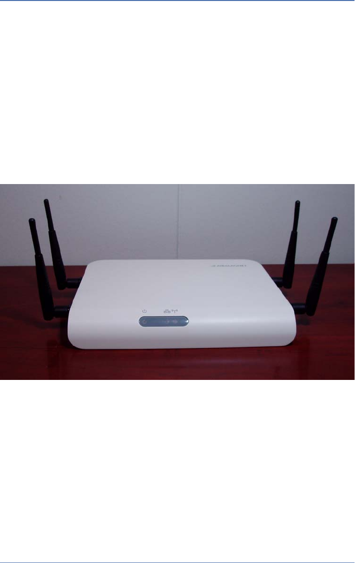
A5200 Sensor Exterior Views
This chapter discusses the physical features of the A5200 Sensor. Figures
2-1 and 2-2 illustrate the exterior of A5200 Sensor from different
perspectives.
Figure 2-1: A5200 Sensor Front/Top View
A5200 Sensor User Guide.book Page 5 Thursday, January 15, 2009 2:00 PM

6Chapter 2: Getting Started
AirMagnet A5200 Sensor User Guide
Figure 2-2: A5200 Sensor Back/Top View
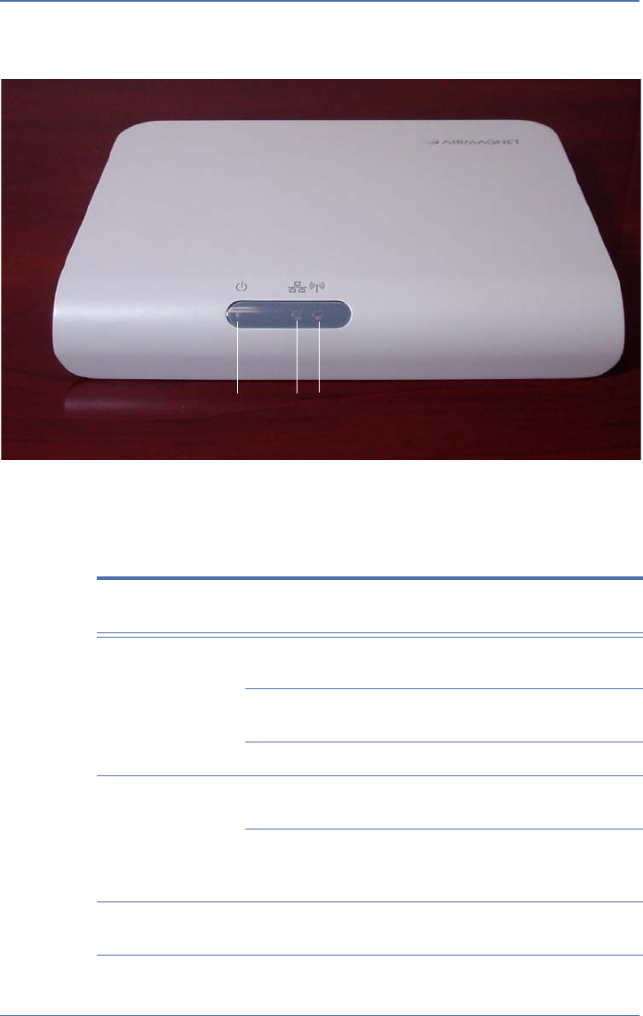
A5200 Sensor LEDs
The front panel of the A5200, as shown in Figure 2-1, has three LEDs
which reflect the working condition of the A5200 Sensor. Figure 2-3 is
a close-up view of the LEDs on A5200 Sensor’s front panel, and Table
2-1 briefly describes each of the LEDs.
A5200 Sensor User Guide.book Page 6 Thursday, January 15, 2009 2:00 PM
AirMagnet A5200 Sensor User Guide
Chapter 2: Getting Started 7
Figure 2-3: A5200 Sensor LEDs
Table 2-1: A5200 Sensor LEDs
LED Color Status Description
Power Green Steady The Sensor is powered up and
ready.
Green Flickering The Sensor is not ready, e.g.,
configuration in progress.
Off The Sensor is powered off.
LAN Green Flickering The Sensor is powered up and
working properly.
Off The Sensor is powered off or its
LAN port is experiencing a
connection problem.
WLAN Green On The Sensor is in Monitor Mode, i.e.,
receiving packets.
Power LAN WLAN
A5200 Sensor User Guide.book Page 7 Thursday, January 15, 2009 2:00 PM
8Chapter 2: Getting Started
AirMagnet A5200 Sensor User Guide
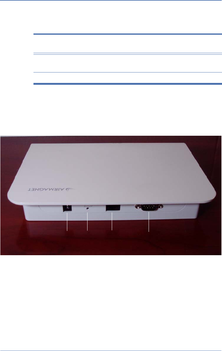
A5200 Sensor Rear Panel Interfaces
Figure 2-4 shows A5200 Sensor’s rear panel which contains the
device’s various interfaces. Table 2-2 provides a brief description of
each of the interfaces.
Figure 2-4: A5200 Sensor Rear Panel
Amber On The Sensor is in Client Mode, i.e.,
sending packets.
Off The Sensor is powered off.
Table 2-1: A5200 Sensor LEDs
LED Color Status Description
Power 12V Reset RJ-45 RS-232
A5200 Sensor User Guide.book Page 8 Thursday, January 15, 2009 2:00 PM

AirMagnet A5200 Sensor User Guide
Chapter 2: Getting Started 9
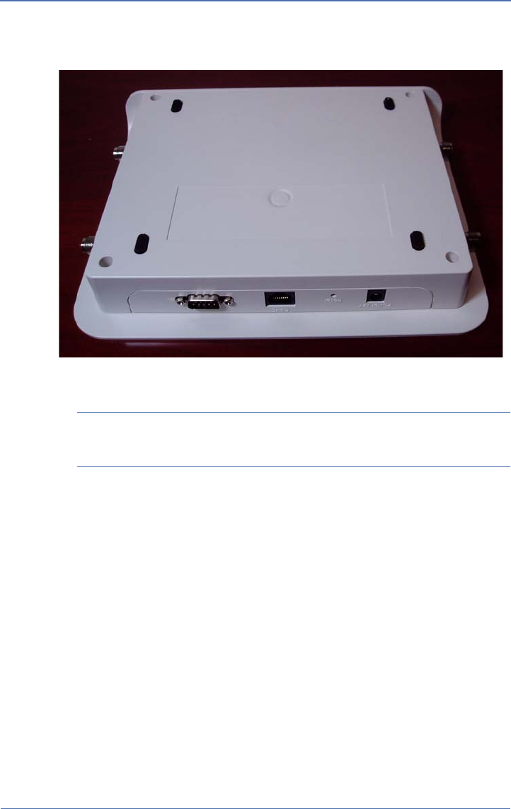
A5200 Sensor RF Connectors
The A5200 Sensor comes with four reverse polarity RP-TNC RF
connectors, with two on each side, as shown in Figure 2-5. They are
intended for mounting four removable omni-directional dipole 2.4-/
5-GHz dual-band rubber-duck antennas.
Table 2-2: A5200 Sensor Interfaces
Interface Description
Power For supplying power to the Sensor using a DC 12V
universal adapter.
Note: This does not apply when PoE is used.
Reset • Pressing and holding down the button for less
than 5 seconds will reboot the Sensor.
• Pressing and holding down the button for more
than 5 seconds will reset the Sensor to its factory
default settings.
RJ-45 (Lan Port) For connecting the Sensor to an Ethernet
network through an RJ-45 Ethernet cable. The RJ-45
comes with built-in 802.3af PoE compliance.
RS-232 (Serial Port) For troubleshooting the Sensor using the
Hyperterminal.
A5200 Sensor User Guide.book Page 9 Thursday, January 15, 2009 2:00 PM
10 Chapter 2: Getting Started
AirMagnet A5200 Sensor User Guide
Figure 2-5: A5200 RF Connectors
Refer to Appendix B: A5200 Standard Antennas for detailed antenna
specifications.
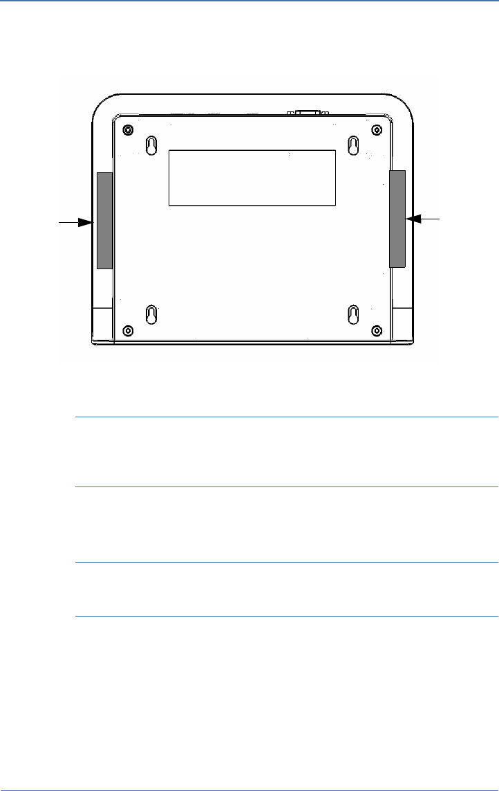
A5200 Bottom Cover
The A5200 Sensor comes with four removable rubber pads on its
bottom cover (shown in Figure 2-5). They help prevent the Sensor
from skidding when deployed on a flat (horizontal) surface without
using the A5231 Mounting Bracket. However, these rubber pads
must be removed when mounting the Sensor onto the Mounting
Bracket. See “Chapter 3: A5200 Sensor Installation” for more
information.
A5200 Sensor User Guide.book Page 10 Thursday, January 15, 2009 2:00 PM

AirMagnet A5200 Sensor User Guide
Chapter 2: Getting Started 11
Applying Tamper-Evident Seals
The tamper-evident seals are intended to prevent tampering of the
AirMagnet SmartEdge Sensors and help network administrators to
easily identify traces of tampering should it have occurred. To
effectively use the tamper-evident seals, care must be taken to ensure
that the seals are applied properly.
The tamper-evident seals are required for AirMagnet Sensors operated
in FIFS mode. The following instructions apply only to Sensors that are
intended to comply with the FIPS requirement.
To apply the tamper-evident seals:
1) Tighten each of the retention screws using a screwdriver, making
sure that they are all tight.
2) Clean the areas where the seals are to be applied.
3) Place the seals over the sides of A5200 Sensor, as shown in Figure
2-7.
A5200 Sensor User Guide.book Page 11 Thursday, January 15, 2009 2:00 PM
12 Chapter 2: Getting Started
AirMagnet A5200 Sensor User Guide
Figure 2-6:Applying tamper-evident seals
Important Make sure that the seals are applied approximately evenly
(50%-50%) to the bottom and the cover of the module, as only one
part of the seal needs to be removed to defeat the seal.
4) Firmly press the seal ends to cover the seam between the bottom
and the cover of the module.
Important Firmly press the entire seal surface onto the module
surface to ensure the best adhesion possible.
5) Record the seal serial numbers and confirm their presence in later
module inspections.
6) Allow 24 hours for the seal adhesive to dry completely.
Seal 2
Seal 1
A5200 Sensor User Guide.book Page 12 Thursday, January 15, 2009 2:00 PM

AirMagnet A5200 Sensor User Guide
Chapter 3:Installing A5200 Sensor 13
Installing A5200 Sensor
Chapter 3:
A5200 Sensor Zero Configuration
The A5200 Sensor comes with a zero configuration feature that
enables users to take an unconfigured Sensor and place it on their
network and have it automatically find and connect to the AirMagnet
Enterprise Server without having to configure the Sensor first. This
concept alleviates the cumbersome steps of configuring and
managing Sensors during deployment. It also reduces the overhead
during regular maintenance cycles.
To take advantage of the Sensor zero configuration feature, the user
must enable the zero configuration feature on the AirMagnet
Enterprise Server. This feature also carries over to the Sensor
properties screen on the AirMagnet Enterprise Console. The user can
change the Sensor’s shared secret key from the Console and have it
automatically forwarded to the Sensor.
For more information on Sensor zero configuration, see AirMagnet
Enterprise User Guide.
Installing the A5200 Sensor
For better performance, the A5200 Sensor should be installed where
maximum field of view (FOV) can be achieved. This means that it
should be deployed in places where it can cover as large an area as
possible with little or no obstruction. For this reason, it is strongly
recommended that the A5231 Mounting Bracket be used when
installing your A5200 Sensor. The instructions below show how to
install the sensor using the mounting bracket.
Installing the A5200 Sensor on a Counter Top
The A5200 Sensor comes with four rubber pads on its bottom. The
pads provide traction that help stabilize the Sensor when it is placed
horizontally on a flat surface.
A5200 Sensor User Guide.book Page 13 Thursday, January 15, 2009 2:00 PM

14 Chapter 3: Installing A5200 Sensor
AirMagnet A5200 Sensor User Guide
To install the A5200 Sensor on counter top:
1) Place the A5200 Sensor on a desired counter top, making sure
that the four rubber pads stay on the bottom of the Sensor for
traction.
2) Connect the Sensor to the LAN using an RJ-45 cable.
3) Connect the Sensor to the power source, unless PoE is used.
Mounting the A5200 Sensor on a Wall
The A5200 Sensor can be mounted on any vertical surface, such as a
wall, using the AirMagnet A5231 Sensor Mounting Bracket.
The A5231 Sensor Mounting Bracket is sold separately. To order the
mounting bracket, contact your AirMagnet reseller or AirMagnet sales.
1) Select the ideal location on a wall with good FOV.
2) Install the A5231 Mounting Bracket, with the four metal feet
facing away from the wall.
3) Remove the four rubber pads from the back of the A5200 Sensor.
4) Align four holes in the back of the Sensor with the metal feet on
the Mounting Bracket.
5) Press the Sensor down slightly to make sure that the metal feet
are fully engaged with the body of the Sensor.
6) Slide the Sensor gently downward until the tab of the Mounting
Bracket clicks onto the Sensor.
Installing A5200 Sensor on a T-Rail
The ceiling of a building is an ideal place for installing the Sensor in
terms of FOV. With the A5231 Mounting Bracket, you can place the
Sensor anywhere on a T-rail on the ceiling.
To install the Sensor on a T-rail:
1) Slide the Sensor onto the Mounting Bracket, making sure that the
Sensor and the Mounting Bracket are fully engaged.
2) Install the A5231 Mounting Bracket on a T-rail.
A5200 Sensor User Guide.book Page 14 Thursday, January 15, 2009 2:00 PM
AirMagnet A5200 Sensor User Guide
Chapter 3: Installing A5200 Sensor 15
See the A5231 Mounting Bracket Installation Guide for detailed
instructions on how to use the A5231 Mounting Bracket.
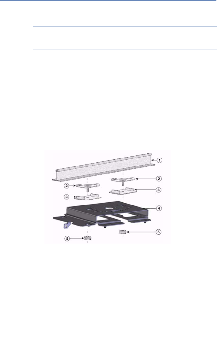
Installing A5200 Sensor with A5031 Mounting Bracket
The A5200 Sensor is backward-compatible with the A5031 Sensor
Mounting Bracket, which not only gives users the same flexibility to
mount the Sensor anywhere they desire, but also offers an additional
security feature that helps prevent the Sensor from tampering and
theft.
To install your A5200 Sensor Using an A5031 Mounting Bracket:
1) Install the A5031 Mounting Bracket where the Sensor is to be
deployed.
Figure 3-1: Assembling the A5031 Mounting Bracket
2) Remove the rubber pads from the A5200 Sensor’s bottom cover.
3) Mount the A5200 Sensor onto the A5031 Mounting Bracket.
Make sure that the four metal knobs on each corner of the Sensor
Adapter Plate are aligned with and set inside the holes on the four
corners of the A5200 Sensor’s bottom cover.
A5200 Sensor User Guide.book Page 15 Thursday, January 15, 2009 2:00 PM
16 Chapter 3: Installing A5200 Sensor
AirMagnet A5200 Sensor User Guide
4) Gently slide the Sensor towards the Locking Plate until it is fully
engaged.
5) Secure the Sensor with padlock.
Powering Up A5200 Sensors
Customers deploying AirMagnet Enterprise can power their
AirMagnet sensors using a standard Ethernet cable, thus avoiding
the need to run the standard electrical wiring to each and every
individual sensor. AirMagnet offers two PoE options, and customers
can typically make their own choice based on the quality of the
switch to which their AirMagnet sensors will be connected.
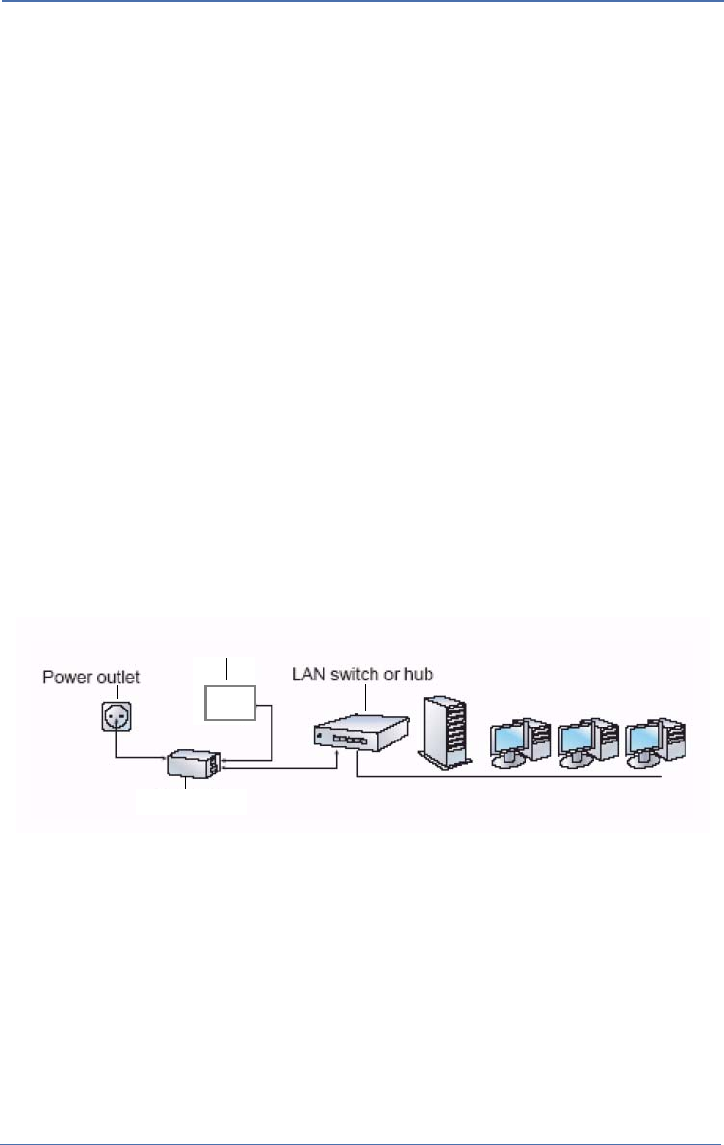
Powering Up via an 802.3af-Compliant PoE Injector
To power up A5200 Sensor via an 802.3af-compliant PoE Injector:
1) Connect the PoE injector (via the Data Only port) to a network
switch or hub, using a 10/100 Ethernet cable.
2) Connect the PoE injector (via the Power and Data port) to A5200
Sensor using another 10/100 Ethernet cable.
3) Plug the power cord into an electrical outlet. See Figure 3-2.
Figure 3-2: Powering up A5200 via 802.3af-compliant
A5200 Sensor
PoE injector
A5200 Sensor User Guide.book Page 16 Thursday, January 15, 2009 2:00 PM
AirMagnet A5200 Sensor User Guide
Chapter 3: Installing A5200 Sensor 17
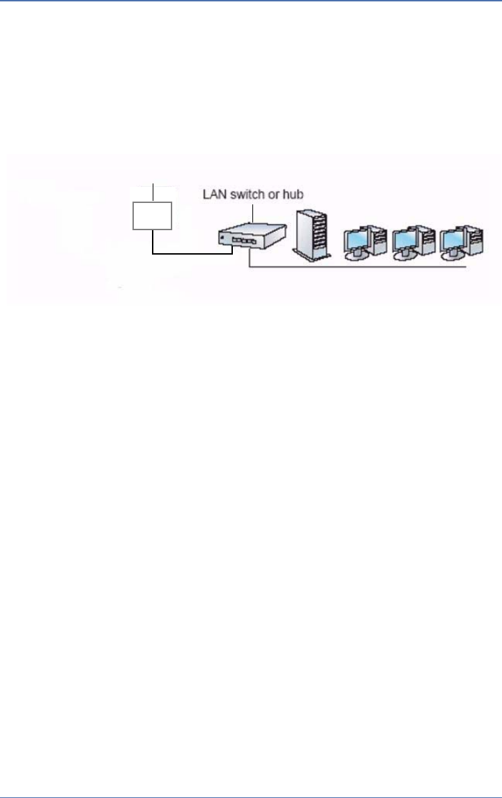
Powering Up Directly via an 802.3af-Compliant Switch
To power up A5200 Sensor directly via an 802.3af-compliant switch:
1) Connect the A5200 Sensor to an IEEE 802.3af-compliant network
switch (e.g, a Cisco Catalyst 3560 Series PoE-24) using a 10/100
Ethernet cable. See Figure 3-3.
Figure 3-3: Powering up A5200 via an 802.3af-compliant switch
A5200 Sensor
A5200 Sensor User Guide.book Page 17 Thursday, January 15, 2009 2:00 PM

18 Chapter 3: Installing A5200 Sensor
AirMagnet A5200 Sensor User Guide
A5200 Sensor User Guide.book Page 18 Thursday, January 15, 2009 2:00 PM

AirMagnet A5200 Sensor User Guide
Appendix A: A5200 Sensor Specifications 19
A5200 Sensor Specifications
Appendix A:
This section contains detailed product specifications of the
AirMagnet A5200 Sensor.
Feature Description
Mechanical • Material meeting UL 2043 Safety and flammability standards
• Removable antennas
•Seismic vibration PCB/Daughter-card/antenna connector
resiliency
•Mounting bracket (chassis to accommodate both wall mounting
and ceiling placement
Environmental •Temperature: 32
o F~131o F (0o C~ 55o C)
• Humidity: 10%~90% (non-condensing) (DC power adapter
exclude)
Processor • Intel IXP 425 533 MHz; clock speed
System
Memory
• 64 MB SDRAM min., with PCB option for adding up to 128 MB
• 16 MB Flash ROM
WiFi Silicon • Mini-PCI dual-band 802.11a/b/g/n, with Atheros chipset
• MB82 (AR9160+9106)
Operating
Voltage
• 12V DC +/- 5%; 48V +/- 10% (802.3af PoE)
Current
Consumption
• Typical 600 mA (12V DC); 180 mA (48V PoE)
Input Power
Requirement
• PoE 802.3af compliant
A5200 Sensor User Guide.book Page 19 Thursday, January 15, 2009 2:00 PM

20 Appendix A: A5200 Sensor Specifications
AirMagnet A5200 Sensor User Guide
Standard
Antennas (Dual
band 2.4/5 GHz)
• Four (default) removable omni-directional dipole dual-band
rubber duck antennas (See Appendix B, “A5200 Standard
Antenna” for more information.
Status LEDs •Power
• WLAN (2.4 GHz/5GHz)
• LAN 10/100 Base-T
LAN Port • RJ-45 with built-in 802.3af PoE compliance
Serial Port • External connector required, DB-9 male connector, RS-232 null
modem
External Switch • Reset switch
DC Input
Connector
• DC power input jack
RF Connectors • Four (default) reverse polarity RP-TNC
Data Rates •802.11a:
6, 9, 12, 18, 24, 36, 48, 54, and 108 Mbps turbo mode
•802.11g:
6, 9, 12, 18, 24, 36, 48, and 54 Mbps
•802.11b:
1, 2, 5.5, and 11 Mbps
• 802.11n: @ 800 GI (400 GI)
20 MHz BW
1 Nss: 65 (72.2) Mbps maximum
2 Nss: 130 (144.444) Mbps maximum
40 MHz BW
1 Nss: 135 (150) Mbps maximum
2 Nss: 270 (300) Mbps maximum
A5200 Sensor User Guide.book Page 20 Thursday, January 15, 2009 2:00 PM

AirMagnet A5200 Sensor User Guide
Appendix A: A5200 Sensor Specifications 21
Frequency
Bands (For
operating in the
US, the
frequency is
fixed; users
cannot change
to other bands)
•802.11a:
5.15~5.25 GHz; 5.25~5.35 GHz; 5.725~5.825 GHz
• 802.11b/g:
2.412~2.462 GHz (US)
2.412~2.272 GHz (Europe ETSI)
2.412~2.484 GHz (Japan)
2.457~2.462 GHz (Spain)
2.457~2.472 GHz (France)
• 802.11n: dual band, same as 802.11a and 802.11b/g (see above)
Receive
Sensitivity
(Typical)
• 802.11a:
-84 dBm @ 6 Mbps
-82 dBm @ 9 Mbps
-79 dBm @ 12 Mbps
-77 dBm @ 18 Mbps
-75 dBm @ 24 Mbps
-73 dBm @ 36 Mbps
-70 dBm @ 48 Mbps
-68 dBm @ 54 Mbps
•802.11b/g:
-91 dBm @ 1 Mbps
-90 dBm @ 2 Mbps
-89 dBm @ 5.5 Mbps
-87 dBm @ 11 Mbps
-84 dBm @ 6 Mbps
-82 dBm @ 9 Mbps
-79 dBm @ 12 Mbps
-77 dBm @ 18 Mbps
-75 dBm @ 24 Mbps
-73 dBm @ 36 Mbps
-70 dBm @ 48 Mbps
-68 dBm @ 54 Mbps
• 802.11n (5 GHz Band):
-63 dBm @ 130 Mbps
-61 dBm @ 270 Mbps
• 802.11n (2.4 GHz Band):
-63 dBm @ 130 Mbps
-61 dBm @ 270 Mbps
A5200 Sensor User Guide.book Page 21 Thursday, January 15, 2009 2:00 PM

22 Appendix A: A5200 Sensor Specifications
AirMagnet A5200 Sensor User Guide
Transmit
Output Power
(Typical)
• 802.11a:
13~15 dBm @ 6~24 Mbps
16 dBm +/-2 @ 36 Mbps
15 dBm +/-2 @ 48 Mbps
13 dBm +/-2 @ 54 Mbps
13 dBm +/-2 @ 108 Mbps
• 802.11b:
13~16 dBm for all rates
• 802.11g:
10~13 dBm @ 6~24 Mbps
10~13 dBm @ 36 Mbps
10~13 dBm @ 48 Mbps
15 dBm +/-2 @ 54 Mbps
• 802.11n:
5 GHz Band
13~15 dBm @ 130 Mbps
13~15 dBm @ 270 Mbps
2.4 GHz Band
9~11 dBm @ 130 Mbps
9~11 dBm @ 270 Mbps
Compliance
A5200 Sensor User Guide.book Page 22 Thursday, January 15, 2009 2:00 PM

AirMagnet A5200 Sensor User Guide
Appendix B: A5200 Standard Antennas 23
A5200 Standard Antennas
Appendix B:
This section contains the specifications of the A5200 Sensor standard antennas.
Feature Description
Standard • IEEE 802.11 a/b/g/n wireless LAN
Length • 143.5 mm (approximately 5.65 in.)
Color •Black
Electrical • Operating Frequency: 2.4 ~ 2.4835 & 5.15 ~ 5.35 & 5.725 ~ 5.85 GHz
• Antenna Type: PCB
• Polarization Type: Linear
• Radiation Type: Toroidal
• Antenna gain: 2.0 dBi typical
• Impedance: 50 Ohm nominal
• V.S.W.R.: 2.0:1 max.
Mechanical • Connector: RP-TNC(M)
•Core: N/A
Raw Material • Coaxial Cable: MIL-C-17 RG-178 B/U
•Housing: TPU
• Hinge: Polycarbonate
A5200 Sensor User Guide.book Page 23 Thursday, January 15, 2009 2:00 PM

24 Appendix B: A5200 Standard Antennas
AirMagnet A5200 Sensor User Guide
A5200 Sensor User Guide.book Page 24 Thursday, January 15, 2009 2:00 PM

AirMagnet A5200 Sensor User Guide
Index 25
Index
Numerics
10/100 Ethernet cable 14
2.4-GHz 1
2.4-GHz RF Connector 8
5-GHz 1
5-GHz RF Connector 8
802.3af-compliant PoE Injector 13
802.3af-Compliant Power Device 13
802.3af-Compliant Switch 14
802.3af-compliant switch 13
A
A5031 Mounting Bracket 1
A5031 Mounting Kit 1
antennas 1
appliance 2
B
bottom cover 9
C
configuration 2
Connector 19, 20
contact 2
D
deployment 11
Dimensions 20, 21
dual-band 1, 8
E
EEPROM 15
electrical outlet 13
electrical wiring 13
Enterprise Console 11
Enterprise Server 2, 11
Environmental 15
Ethernet Base-T port 1
Ethernet cable 13
exterior 5
F
FAQ 2
field of view 11
Frequency Bands 16
front panel 6
H
high-gain 19
high-gain antennas 8
high-gain dual-band antenna 19, 20
HPBW/Horizontal 19, 20
HPBW/Vertical 19, 20
hub 13
Humidity 20, 21
I
Impedance 19, 20
Information Sheet 1
install 11
A5200 Sensor User Guide.book Page 25 Thursday, January 15, 2009 2:00 PM

26 Index
AirMagnet A5200 Sensor User Guide
installation procedures 2
Intel 1
interfaces 7
K
key features 2
L
LAN 6
LAN Port 8, 16
LEDs 6
Locking Plate 1, 13
M
maintenance 11
Mechanical 15
Mounting Bracket 9
N
network 13
O
Out-of-Warranty Repairs iii
P
physical features 5
plug-and-play 2
PoE 13
PoE injector 13
Polarization 19, 20
Power 6, 8
power 13
Power handling 19
processing speed 1
Processor 15
product package 1
Product Registration 5
Product Repairs ii
Products Warranty i
R
Radome color 20, 21
Radome material 20, 21
rear panel 7
Reboot/Reset Button 8
regulatory compliance standards 19
removable 1
reseller 2
Return Material Authorization ii
RF 15
RMA ii
rubber pads 9, 12
S
Serial Port 8, 16
shared secret key 11
single-band 8
skidding 9
SmartEdge Sensor 1
specifications 15
standard 1, 8
switch 13
System Memory 15
T
Tamper-Evident Seals 9
technical support 2, 3
Temperature 20, 21
U
unconfigured 11
A5200 Sensor User Guide.book Page 26 Thursday, January 15, 2009 2:00 PM


28 Index
AirMagnet A5200 Sensor User Guide
A5200 Sensor User Guide.book Page 28 Thursday, January 15, 2009 2:00 PM
Federal Communication Commission Interference Statement
This equipment has been tested and found to comply with the limits for a Class B digital device,
pursuant to Part 15 of the FCC Rules. These limits are designed to provide reasonable
protection against harmful interference in a residential installation. This equipment generates,
uses and can radiate radio frequency energy and, if not installed and used in accordance with
the instructions, may cause harmful interference to radio communications. However, there is
no guarantee that interference will not occur in a particular installation. If this equipment does
cause harmful interference to radio or television reception, which can be determined by turning
the equipment off and on, the user is encouraged to try to correct the interference by one of the
following measures:
- Reorient or relocate the receiving antenna.
- Increase the separation between the equipment and receiver.
- Connect the equipment into an outlet on a circuit different from that to which the receiver is
connected.
- Consult the dealer or an experienced radio/TV technician for help.
FCC Caution: Any changes or modifications not expressly approved by the party responsible for
compliance could void the user's authority to operate this equipment.
For operation within 5.15 ~ 5.25GHz frequency range, it is restricted to indoor environment.
This device complies with Part 15 of the FCC Rules. Operation is subject to the following two
conditions: (1) This device may not cause harmful interference, and (2) this device must accept
any interference received, including interference that may cause undesired operation.
IMPORTANT NOTE:
Radiation Exposure Statement:
This equipment complies with FCC radiation exposure limits set forth for an uncontrolled
environment. This equipment should be installed and operated with minimum distance 20cm
between the radiator & your body.
This transmitter must not be co-located or operating in conjunction with any other antenna or
transmitter.
The availability of some specific channels and/or operational frequency bands are country
dependent and are firmware programmed at the factory to match the intended destination. The
firmware setting is not accessible by the end user.
A5200 / A5205 with Embedded type antenna and max. antenna gain is 5.1dBi in 5G and 2.8dBi
in 2.4G.
Industry Canada statement
This device complies with RSS-210 of the Industry Canada Rules. Operation is subject to the
following two conditions: (1) This device may not cause harmful interference, and (2) this device
must accept any interference received, including interference that may cause undesired
operation.
IMPORTANT NOTE:
IC Radiation Exposure Statement:
This equipment complies with IC radiation exposure limits set forth for an uncontrolled
environment. This equipment should be installed and operated with minimum distance 20cm
between the radiator and your body.
Industry Canada Interference Statement
The device for the band 5150-5250 MHz is only for indoor usage to reduce potential for harmful
interference to co-channel mobile satellite systems;
The maximum antenna gain 5.1dBi permitted (for devices in the bands 5250-5350 MHz and
5470-5725 MHz) to comply with the e.i.r.p. limit; and
The maximum antenna gain 4.5dBi permitted (for devices in the band 5725-5825 MHz) to
comply with the e.i.r.p. limits specified for point-to-point and non point-to-point operation as
appropriate, as stated in section A9.2(3).
In addition, users should also be cautioned to take note that high-power radars are allocated as
primary users (meaning they have priority) of the bands 5250-5350 MHz and 5650-5850 MHz
and these radars could cause interference and/or damage to LE-LAN devices.

Europe – EU Declaration of Conformity
This device complies with the essential requirements of the R&TTE Directive 1999/5/EC.
The following test methods have been applied in order to prove presumption of
conformity with the essential requirements of the R&TTE Directive 1999/5/EC:
- EN60950-1: (2006)
Safety of Information Technology Equipment
- EN50385 : (2002-08)
- Product standard to demonstrate the compliance of radio base stations and fixed
terminal stations for wireless telecommunication systems with the basic restrictions
or the reference levels related to human exposure to radio frequency
electromagnetic fields (110MHz - 40 GHz) - General public
- EN 300 328 V1.7.1: (2006-10)
- Electromagnetic compatibility and Radio spectrum Matters (ERM); Wideband
Transmission systems; Data transmission equipment operating in the 2,4 GHz ISM
band and using spread spectrum modulation techniques; Harmonized EN covering
essential requirements under article 3.2 of the R&TTE Directive
- EN 301 893 V1.4.1: (2007-07)
- Broadband Radio Access Networks (BRAN);5 GHz high performance RLAN;
Harmonized EN covering essential requirements of article 3.2 of the R&TTE
Directive
EN 301 489-1 V1.8.1: (2008-04)
- Electromagnetic compatibility and Radio Spectrum Matters (ERM); ElectroMagnetic
Compatibility (EMC) standard for radio equipment and services; Part 1: Common
technical requirements
- EN 301 489-17 V1.3.2 (2008-04)
- Electromagnetic compatibility and Radio spectrum Matters (ERM); ElectroMagnetic
Compatibility (EMC) standard for radio equipment; Part 17: Specific conditions for
2,4 GHz wideband transmission systems, 5 GHz high performance RLAN equipment
and 5,8 GHz Broadband Data Transmitting Systems
-
This device is a 2.4 GHz wideband transmission system (transceiver), intended for use
in all EU member states and EFTA countries, except in France and Italy where
restrictive use applies.
In Italy the end-user should apply for a license at the national spectrum authorities in
order to obtain authorization to use the device for setting up outdoor radio links and/or
for supplying public access to telecommunications and/or network services.
This device may not be used for setting up outdoor radio links in France and in some
areas the RF output power may be limited to 10 mW EIRP in the frequency range of
2454 – 2483.5 MHz. For detailed information the end-user should contact the national
spectrum authority in France.
0560

Česky
[Czech]
[Jméno výrobce] tímto prohlašuje, že tento [typ zařízení] je ve shodě se základními
požadavky a dalšími příslušnými ustanoveními směrnice 1999/5/ES.
Dansk
[Danish]
Undertegnede [fabrikantens navn] erklærer herved, at følgende udstyr [udstyrets
typebetegnelse] overholder de væsentlige krav og øvrige relevante krav i direktiv
1999/5/EF.
Deutsch
[German]
Hiermit erklärt [Name des Herstellers], dass sich das Gerät [Gerätetyp] in
Übereinstimmung mit den grundlegenden Anforderungen und den übrigen
einschlägigen Bestimmungen der Richtlinie 1999/5/EG befindet.
Eesti
[Estonian]
Käesolevaga kinnitab [tootja nimi = name of manufacturer] seadme [seadme tüüp =
type of equipment] vastavust direktiivi 1999/5/EÜ põhinõuetele ja nimetatud direktiivist
tulenevatele teistele asjakohastele sätetele.
English Hereby, [name of manufacturer], declares that this [type of equipment] is in compliance
with the essential requirements and other relevant provisions of Directive 1999/5/EC.
Español
[Spanish]
Por medio de la presente [nombre del fabricante] declara que el [clase de equipo]
cumple con los requisitos esenciales y cualesquiera otras disposiciones aplicables o
exigibles de la Directiva 1999/5/CE.
Ελληνική
[Greek]
ΜΕ ΤΗΝ ΠΑΡΟΥΣΑ [name of manufacturer] ΔΗΛΩΝΕΙ ΟΤΙ [type of equipment]
ΣΥΜΜΟΡΦΩΝΕΤΑΙ ΠΡΟΣ ΤΙΣ ΟΥΣΙΩΔΕΙΣ ΑΠΑΙΤΗΣΕΙΣ ΚΑΙ ΤΙΣ ΛΟΙΠΕΣ ΣΧΕΤΙΚΕΣ
ΔΙΑΤΑΞΕΙΣ ΤΗΣ ΟΔΗΓΙΑΣ 1999/5/ΕΚ.
Français
[French]
Par la présente [nom du fabricant] déclare que l'appareil [type d'appareil] est conforme
aux exigences essentielles et aux autres dispositions pertinentes de la directive
1999/5/CE.
Italiano
[Italian]
Con la presente [nome del costruttore] dichiara che questo [tipo di apparecchio] è
conforme ai requisiti essenziali ed alle altre disposizioni pertinenti stabilite dalla direttiva
1999/5/CE.
Latviski
[Latvian]
Ar šo [name of manufacturer / izgatavotāja nosaukums] deklarē, ka [type of equipment
/ iekārtas tips] atbilst Direktīvas 1999/5/EK būtiskajām prasībām un citiem ar to
saistītajiem noteikumiem.
Lietuvių
[Lithuanian]
Šiuo [manufacturer name] deklaruoja, kad šis [equipment type] atitinka esminius
reikalavimus ir kitas 1999/5/EB Direktyvos nuostatas.
Nederlands
[Dutch]
Hierbij verklaart [naam van de fabrikant] dat het toestel [type van toestel] in
overeenstemming is met de essentiële eisen en de andere relevante bepalingen van
richtlijn 1999/5/EG.
Malti
[Maltese]
Hawnhekk, [isem tal-manifattur], jiddikjara li dan [il-mudel tal-prodott] jikkonforma mal-
ħtiġijiet essenzjali u ma provvedimenti oħrajn relevanti li hemm fid-Dirrettiva 1999/5/EC.
Magyar
[Hungarian]
Alulírott, [gyártó neve] nyilatkozom, hogy a [... típus] megfelel a vonatkozó alapvetõ
követelményeknek és az 1999/5/EC irányelv egyéb elõírásainak.
Polski
[Polish]
Niniejszym [nazwa producenta] oświadcza, że [nazwa wyrobu] jest zgodny z
zasadniczymi wymogami oraz pozostałymi stosownymi postanowieniami Dyrektywy
1999/5/EC.
Português
[Portuguese]
[Nome do fabricante] declara que este [tipo de equipamento] está conforme com os
requisitos essenciais e outras disposições da Directiva 1999/5/CE.
Slovensko
[Slovenian]
[Ime proizvajalca] izjavlja, da je ta [tip opreme] v skladu z bistvenimi zahtevami in
ostalimi relevantnimi določili direktive 1999/5/ES.
Slovensky [Meno výrobcu] týmto vyhlasuje, že [typ zariadenia] spĺňa základné požiadavky a

[Slovak] všetky príslušné ustanovenia Smernice 1999/5/ES.
Suomi
[Finnish]
[Valmistaja = manufacturer] vakuuttaa täten että [type of equipment = laitteen
tyyppimerkintä] tyyppinen laite on direktiivin 1999/5/EY oleellisten vaatimusten ja sitä
koskevien direktiivin muiden ehtojen mukainen.
Svenska
[Swedish]
Härmed intygar [företag] att denna [utrustningstyp] står I överensstämmelse med de
väsentliga egenskapskrav och övriga relevanta bestämmelser som framgår av direktiv
1999/5/EG.